
Powder Actuated Fastenings
Powder Actuated
PRODUCT INFORMATION
Powder Actuated Fastenings
SECTION CONTENTS Page No.
INTRODUCTION
Powder actuated fastening systems provide a cost effective method of attaching fixtures for
light duty, static load conditions. Powers’ systems consist of specially designed fasteners,
installation tools, and powder loads which are designed to function in combination to provide
optimum performance.
These systems provide the contractor with the ability to fasten directly into concrete, masonry,
and structural steel without pre-drilling holes.
GENERAL APPLICATIONS AND USES
i• Attaching Steel to Concrete, Block or Steel
• Attaching Wood members to Concrete, Block or Steel
• Attaching accessories to Concrete, Block or Steel
• Attaching ceiling clips and threaded rod to Concrete or Steel
Functioning Principles.................... 3
Powder Loads............................... 4
Fastener Types............................. 4
Functioning in Concrete............... 5
Functioning in Steel..................... 5
Fastener Behavior........................ 6
Base Material Suitability.............. 7
Applied Loads............................... 7
Design Reference Guide
for Concrete................................. 7
Design Reference Guide
for Steel........................................ 9
Performance Data...................... 10
APPROVALS AND LISTINGS • Tested in accordance to ASTM E 488 and E 1190
• International Code Council, Evaluation Service (ICC-ES), ESR-2024 (Formerly ER-5330)
• International Code Council, Evaluation Service (ICC-ES), ESR-1995
• City of Los Angeles (COLA) Research Report LARR-25304
• FM Global (Factory Mutual) - File No. J.I. 3002070 (Threaded Studs)
FUNCTIONING PRINCIPLES
Operating Principle
Powder actuated systems, often described as forced entry
systems, require special installation tools which are critical
components of a successful fastening. Two types of tools have
been used in the market which operate on different driving
principles, direct acting and indirect acting. The basic design
of the tools are similar in that each has a breech which holds
the powder load and a barrel or guide mechanism to hold the
fastener. However, the installation and safety characteristics
of the tools are very different.
Direct Acting Principle
As the powder load is ignited in a direct acting tool, the expanding
gases of the load act directly on the fastener
to drive it down the barrel of the tool and into
the base material. In a tool of this type, 100%
of the energy developed by the powder load
is transferred to the fastener. Penetration of
the fastener into the base material is controlled
primarily by the density of the base material and
the load level selected. While the direct acting
principle may allow fastenings to be made
in very dense concrete and thick steel base materials, safety
concerns have made the indirect principle the technology of
choice. Powder actuated tools using this principle
are no longer commercially available.
Indirect Acting Principle
In a tool which operates using the indirect acting principle, the
expanding gases of the ignited powder load
act directly on a captive piston which is housed
within the barrel of the tool.
The piston drives the fastener into the base
material providing better control over the
penetration of the fastener. In a tool of this type,
most of the energy developed by the powder
load is retained by the piston. Penetration of
1
www.powers.com
the fastener into the base material is controlled by the design of
the piston, the load level selected, and the density of the base
material. All Powers’ powder actuated tools operate using the
indirect acting principle and are classified as low velocity tools.
Tool Classification
Powder actuated tools can be classified as low, medium, or
high velocity. This classification system can apply to either direct
or indirect acting tools and is based on a ballistic test. Using the
strongest powder load and the lightest fastener commercially
available from the manufacturer for a specific tool, the velocity
of the tool is determined by measuring the average velocity of
the fastener for ten individual tests. The velocity classifications
based on ANSI A10.3 are as follows:
1. Low Velocity Tool
A tool in which the average test velocity does not exceed
328 feet per second (100 meters per second).
2. Medium Velocity Tool
A tool in which the average test velocity exceeds 328 feet
per second (100 meters per second) but is less than 492
feet per second (150 meters per second). Medium velocity
tools are no longer commercially available.
3. High Velocity Tool
A tool in which the average test velocity exceeds 492 feet
per second (150 meters per second). High velocity tools are
no longer commercially available.
Tool Safety
Powder actuated fasteners must be installed by properly
trained and licensed operators as described in ANSI Standard
A 10.3. Authorized Powers distributors offer complete training
programs for end users. Contact your local Powers branch
office or distributor for complete details. While the powder
actuated tools are summarized in this section of the manual,
only trained and licensed operators are allowed to use the tools.
These summaries are for general information only.
Canada: (905) 673-7295 or (514) 631-4216
Powers USA: (800) 524-3244 or (914) 235-6300
D
Powder Actuated
PRODUCT INFORMATION
POWDER LOADS
The energy source used to drive a powder actuated fastener
into the base material is a self contained unit called a powder
load. Specific load types are designed for each unique powder
actuated tool. Powers tools use cased powder loads in which
the propellant is housed in a crimped metal case.
Powder Load Identification
In the commercial market, cased powder loads are available
in sizes ranging from .22 to .27 calibers. The power level or
strength of a cased powder load is identified using a 12 level
system in which a combination of six color codes and two case
types are used. Power level 1/gray is the lowest with power
level 12/purple being the highest. Only six color codes are
used because there are not twelve easily distinguished colors
available. The following table shows this identification system.
Power Level
1
2
3
4
4.5
5
6
7
8
9
10
11
12
Color Identification
Case Color
Load Color
Brass
Gray
Brass
Brown
Brass
Green
Brass
Yellow
Brass
Blue
Brass
Red
Brass
Purple
Nickel
Gray
Nickel
Brown
Nickel
Green
Nickel
Yellow
Nickel
Red
Nickel
Purple
Powder loads are available as single units for single shot tools
and collated in groups of 10 into plastic strips or metal discs for
semi-automatic tools. Powers tools use .22 caliber A, .25 caliber,
and .27 caliber crimped, rim fire powder loads having power
levels ranging from 1-6.
Powder loads for other
commercially available tools
are also available such as .22
caliber Ladd and .27 caliber
long. Consult the individual tool
instructions for details on the
caliber, range, and type of load.
The crimped tip on the load retains the powder in the casing.
Wadded loads which have a plug in the front of the casing
should never be used in tools designed for use with crimped
loads such as low velocity, piston tools. The wadding material
can cause the tool to clog or jam. Rim fire refers to the method
of actuation. In a rim fire powder load, the primer is contained
in the rim of the casing. When the tool is fired, the firing pin
strikes the rim causing the primer to ignite which in turn ignites
the powder contained in the main portion of the load. The
power level of Powers powder loads is marked on each box.
As the number increases, the power level also increases. Power
level is also indicated by the color of the box, label, and the
color on each individual powder load.
Powder Load Selection
Use of the proper power level is critical to the success of a
powder actuated fastening. Prior to selecting the proper power
level, conduct a center punch test as described in the upcoming
section on base material suitability. To select the proper power
level to be used with a specific fastener, always perform a test
firing using the lowest power level recommended for the tool
being used. On tools which have a variable power control,
use the lowest possible setting. If the lowest power level does
not fully drive the fastener, try a powder load having the next
higher power level. Continue this procedure until the proper
fastener penetration is obtained.
FASTENER TYPES
Several fastener types are available including drive pins and
threaded studs along with application-specific assemblies.
According to ANSI A 10.3, only those types of fasteners and
powder loads as recommended by the tool manufacturer for a
particular tool, or those providing the same level of safety and
performance, shall be used.
Typical Drive Pins
.300” Head
Ballistic Point
Drive pins are one of the most commonly specified type of
powder actuated fastener. They are used to fasten a fixture
directly to the base material in one operation for permanent
applications. Pins are available in several head configurations.
Each of the head configurations has a corresponding shank
diameter and a variety of lengths. Some drive pins designed
for use in steel have a knurled shank to provide increase load
capacities. Other drive pins have a narrow shank diameter close
to its point and a wider shank diameter comprising the upper
portion. This design is known as “step shank” and is used to
penetrate denser base materials more consistently.
.300” Head
8mm Head
10mm Head
3/8” Head
Powers USA: (800) 524-3244 or (914) 235-6300
Threaded Studs
For applications where adjustment or removability may be
required, threaded studs are available with both a 1/4” or 3/8”
thread diameter. Each thread size has a corresponding shank
diameter and is available in a variety of shank and thread lengths.
Canada: (905) 673-7295 or (514) 631-4216
www.powers.com
D
2
Powder Actuated
PRODUCT INFORMATION
POWDER LOADS
Fastener Guidance
Fastener Material Specifications
Both types of fastener
have pre-mounted
plastic fluting or washers
Head
Point
which hold the fastener
Guidance
Guidance
centered in the tool
guide prior to driving.
During the driving
process, the fluting or
washers provide point guidance for the fastener. Generally,
head guidance is provided by the diameter of the fastener head
or threads. 1/4”-20 threaded studs also have a plastic cap to
protect the threads of the fastener during the driving process
providing head guidance.
Mechanical Properties
Powder actuated fasteners are subjected to extremely high
stresses as they are driven into the base material. A key aspect
of their design is to manufacture them from a material that is
tough enough to prevent deformation of the fastener during
the driving process with ductility to prevent shattering. Powers
fasteners are specially manufactured using a proprietary process
to meet these requirements. The fasteners are manufactured
from ASTM A 510 SAE 1060 steel and austempered to a
nominal core hardness of RC 51 to 55.
Corrosion Resistance
Powder actuated fasteners are designed to be used in a
non-corrosive atmosphere unless application specific corrosion
testing has been performed. To reduce the possibility of the
embrittlement of a heat treated part, the standard finish for
all Powers fasteners is mechanically applied zinc meeting the
requirements of ASTM B 695, Class 5, Type 1 providing an
average minimum thickness of 5 microns (0.0002”) with no
supplementary coating.
FUNCTIONING OF POWDER ACTUATED FASTENINGS
Functioning in Concrete
The load capacity of a powder actuated fastener when installed
into concrete or masonry base materials is based on the following
factors:
1. Strength of the base material
2. Hardness and concentration of the aggregate
3. Shank diameter of the fastener
4. Depth of embedment into the base material
5. Fastener spacing and edge distance
In addition to these factors, installation tool accessories such as
a stop spall guard adapter which reduces the tendency of the
concrete surface to spall during the driving action can increase
the performance of the fastener.
When a powder actuated fastener is driven into concrete, it
displaces the volume of concrete around the embedded area
of the fastener shank. As this occurs, the concrete directly
surrounding the fastener is compressed and in turn presses back
against the shank of the fastener. Additionally, the driving action
generates heat which causes particles within the concrete to fuse
to the shank of the fastener. This combination of compression
and fusion holds the fastener in the concrete base material.
A similar action occurs when fastening into block masonry.
capacities. For typical embedment depths achieved, refer to the
upcoming section on performance data andload capacities.
Washer
Stop
Spall
During the driving action, some localized surface spalling of the
concrete may occur. Normally, this is a surface effect which does
not affect the performance of the fastener. However, it may pose
an aesthetic problem for exposed applications where a fixture is
not used. In cases such as this, two methods can be used to
improve the appearance of the fastening. A stop spall adapter
mounted on the powder actuated tool can help to reduce
surface spalling. Another method used is to drive the fastener
through a steel washer to improve the appearance of the
application.
Functioning in Steel
The load capacity of a powder actuated fastener when installed
into steel base materials is based on the following factors:
1. Thickness of the steel
2. Tensile strength of the steel
3. Shank diameter of the fastener
4. Depth of point penetration through the steel
5. Fastener spacing and edge distance.
Generally, the performance of the fastener in a given concrete
strength will increase with greater embedment depths in a
certain range. Depending on the fastener style and base material
strength, embedment depths range from 5/8” to 1-1/2”. For
depths greater than this range, there is the possibility of fastener
bending or “fishhooking” which may decrease expected load
3
www.powers.com
Canada: (905) 673-7295 or (514) 631-4216
D
Powers USA: (800) 524-3244 or (914) 235-6300
PRODUCT INFORMATION
Powder Actuated
Functioning in Steel (Continued)
When a powder actuated fastener is driven into steel, it displaces
the steel laterally 360 degrees around the shank of the fastener.
Since steel is an elastic material, it presses back against the shank
of the fastener to hold it in place. As the diameter of the fastener
shank is increased, the load capacity obtained will generally increase
provided the steel thickness is sufficient to accept the fastener.
To further increase fastener performance in steel, some fasteners
have a knurled shank which allows the steel to form a key lock
into the grooves to provide higher capacities than those obtained
with a smooth shank. For typical performance, the fastener point
should completely penetrate the steel. Normally, a minimum of
1/4” is allowed for the point length. An increase in performance
can normally be expected until the fastener no longer completely
penetrates through the steel. At this point, the elastic properties
of the steel may cause a compression force to be developed at an
angle against the fastener point which can reduce load capacity.
However, this can be subject to the fastener type and in thicker
steel base materials, adequate load capacities may be obtained
for applications in which the point of the fastener does not fully
penetrate the steel. Job site performance tests are recommended.
Fasteners should not be used in areas that have been welded
or cut with a torch as these procedures may have caused local
hardening of the steel. Over driving of the fastener should be
avoided as the rebound created may reduce the load capacity
or cause damage to both the fastener and the tool. When fastening
into unsupported long steel members, it may be necessary to
provide support in the area of the fastening to prevent spring action
which can cause inconsistent penetration and a reduction in load
capacity.
FASTENER BEHAVIOR An understanding of the performance characteristics of a powder
actuated fastener is an important aspect of the selection process.
At ultimate failure, the following modes of failure can be expected.
Bearing Failure
The fixture or material fastened tears as a lateral load is applied
and is pulled over the head of the fastener.
Base Material Failure Fastener Pullout
The fastener pulls out of the base material when subjected to
a tension load. In concrete, a typical cone type failure can be
expected while in steel the fastener pulls out cleanly.
Tightening Failure
On threaded studs, the tightening torque applied must be limited
to prevent over tightening of the connection. This will prevent
the development of a clamping force greater than the tension or
pullout load resistance of the fastener.
Pullover Failure
The fixture or material fastened pulls over the head of the
fastener. This is a common occurrence when fastening lumber
or thin metal materials. To help improve pullover resistance for
applications such as this, Powers powder actuated fasteners are
available with pre-mounted steel washers.
Shank Failure
The shank of the fastener is broken due to an applied lateral
load such as shear. This can also happen when a bending load
is created.
D
Powers USA: (800) 524-3244 or (914) 235-6300
Canada: (905) 673-7295 or (514) 631-4216
www.powers.com
4
Powder Actuated
PRODUCT INFORMATION
BASE MATERIAL SUITABILITY While powder actuated fasteners can be used successfully in
concrete, certain masonry materials, A36 and A572 steel, some
materials are completely unsuitable. Fasteners should never be fired
into hard or brittle materials such as cast iron, tile, glass,
or rock. These materials can shatter easily resulting in a potential
safety hazard. In addition, soft base materials such as wallboard,
plaster, or wood are not appropriate as the fastener could pass
completely through these materials. The user should never guess
when fastening into any base material.
A Center Punch Test should always be performed to help determine
the suitability of the base material for a powder actuated fastening.
This test is relatively simple and can help to ensure a safe, successful
fastening. Be sure to wear the appropriate eye protection when
performing this test. To begin, select the fastener to be used for the
job. Then place the point of the fastener against the proposed base
material. Strike the fastener with a single hammer blow and then
examine the point. If the point of the fastener is not blunted and
the base material has a clear point indentation, it is acceptable to
proceed with the first test installation.
Use of a powder actuated system is not recommended if the
following occurs during the Center Punch Test:
Point
Flattens
No Indent
1. The fastener point has
been blunted. This
indicates that the base
material is too hard.
Surface Shatters
Fastener Sinks in with
Average Hammer Blow
Material Cracks
2. The base material
cracks or shatters. This
indicates that the base
material is too brittle.
3. When using an average
hammer blow, the
fastener penetrates the
base material easily.
This indicates that
the base material is
too soft.
APPLIED LOADS The type of load and the manner in which it is applied by
the fixture or other attachment is a primary consideration in
the selection of a powder actuated fastener. Powder actuated
fastening systems provide a cost effective method of attaching
fixtures for light duty, static load conditions. The load capacities
for powder actuated fasteners published in this manual represent
the results of laboratory testing conducted according to ASTM
Standards E 488 and E 1190. As always, the suitability of a
fastener for a specific application should be determined by
a qualified design professional responsible for the product
installation.
Tension Load
A tension load is applied
directly in line with the axis
of the fastener.
Shear Load
A shear load is applied
perpendicular to the fastener
directly along the surface of
the base material.
Bending Loads
The effect of bending resulting from
the application of static shear load
should be considered. This can occur
in softer material such as lumber used
for sill plates or when shims or spacers
are placed between the fixture and
the base material. In situations such as this, the load is applied at
a distance from the surface of the base material creating a lever
type action on the fastener. When a bending load is applied to a
fastener, it is often the physical strength of the fastener material,
not the tension or shear load capacities, that limit the strength
of the connection. For sill plate applications, Powers publishes
test data based on the use of 2x lumber to develop the
capacities. The allowable bending load should be calculated
by a design professional based on the material from which
the fastener is manufactured. For threaded powder actuated
fasteners and step shank pins, it is important to remember that
the point of maximum stress is at the interface of the shank
and the base material. For example, when calculating the
bending load for a fastener such as a 1/4”-20 threaded stud,
it is important to use the shank diameter of 0.145” in
calculations, not the 0.211” root diameter of the threads.
DESIGN REFERENCE GUIDE FOR LOADS
Allowable Load Capacities
The allowable load capacity which may be applied to a powder
actuated fastener is based on applying a safety factor to the average
ultimate load capacity obtained from testing according to ASTM
Standards E 488 and E 1190. One purpose of the safety factor is to
allow for field variations which may differ from the testing conditions
in the laboratory. An example is the type and strength of the base
material. For proper performance, powder actuated fasteners must
be installed by properly trained and licensed operators. In concrete
and masonry materials, the values for allowable loads are based on
applying a minimum safety factor of 5:1 or greater to the ultimate
5
www.powers.com
loads. Loads are based on testing fasteners installed in base materials
having the designated strength at the time of installation. Values are
for the fastener only, connected parts must be investigated separately.
Due to the variability of powder actuated fasteners installed in concrete
or masonry materials, use of multiple fasteners is recommended to
increase reliability. The design data listed in the tables are suggested
allowable load capacities based on the noted safety factors. These
safety factors are based on industry experience and may need to be
increased based on the application requirements or local codes as
determined by the design professional responsible for the product
installation. Proper spacing and edge distance guidelines must be
followed.
Canada: (905) 673-7295 or (514) 631-4216
Powers USA: (800) 524-3244 or (914) 235-6300
D
Powder Actuated
PRODUCT INFORMATION
DESIGN REFERENCE GUIDE FOR LOADS (Continued)
Base Material Strength
Spacing
As discussed earlier in this manual, the strength of concrete
and masonry base materials can vary widely. For installations
in concrete, load capacities are published for powder actuated
fasteners in normal-weight concrete in various compressive
strength ranges. Linear interpolation of the data to calculate
load capacities for fasteners installed in intermediate concrete
strengths is permitted. Normally, the load capacities can
be expected to increase as the compressive strength of the
concrete base material increases. However, some types of high
compressive strength concrete or concrete with a very hard
aggregate may not be suitable for powder actuated fastenings.
Job site installation tests are recommended to determine
fastener suitability. For structural lightweight concrete, values
are published for minimum 3000 psi concrete with and without
steel deck. For masonry base materials, the published load
capacities are based on testing in a wall constructed from
ASTM C 90, Grade N, lightweight block. Since the consistency
of masonry block can vary widely, especially within the mortar
used, these values should be used solely as a guide. Job site
tests are recommended to determine actual load capacities
when used in masonry walls.
Setting fasteners too close together in concrete or masonry can
cause cracking. The recommended minimum distance between
fasteners is 3” center to center. Unless specific fastener testing
has been conducted to qualify the condition and location.
Length Selection
For permanent applications using pins in concrete, first determine
the thickness of the fixture to be fastened. To this, add the
required embedment or penetration into the base material. This
will be the fastener shank length required. For applications in the
face shell of masonry block, select a fastener length which will
not exceed the thickness of the face shell.
Fixture
Threaded Length
Base Material Thickness
Embedment
Penetration
3x
Penetration
Concrete base material should be at least three (3) times as
thick as the fastener embedment penetration Unless specific
fastener testing has been conducted to qualify the condition
and location. If the concrete is too thin, the compressive forces
forming at the fasteners point can cause the free face of the
concrete to break away. This can create a dangerous condition
from flying concrete and/or the fastener and also results in a
reduction of fastener holding power. For applications in the
face shell of concrete masonry block, select a fastener length
which will not exceed the thickness of the face shell.
Embedment
For removable applications with threaded studs, the shank
length required is equal to the embedment depth required. To
determine the minimum threaded length, add the thickness
of the fixture and the nut / washer thickness. The nut and
washer thickness is equal to the nominal thread diameter.
For applications where 3/8” threaded studs are used at an
embedment depth of 1-3/8”, the fasteners were driven up to
the threaded portion of the part. Do not over tighten threaded
parts. Maximum tightening torque values are listed in the
table below. Use of a nut setter is recommended to reduce
the possibility of over tightening ]the fasteners. For critical
applications, perform a job site test.
Maximum Torque
for 1/4” Stud (ft.-lbs.)
2
Maximum Torque
for 3/8” Stud (ft.-lbs.)
4
Edge Distance
Do not fasten closer than 3” from the edge of concrete. If the
concrete cracks, the fastener may not hold. Closer edge distances
for applications such as sill plates may be permitted if specific
fastener testing has been conducted to qualify the location.
D
Powers USA: (800) 524-3244 or (914) 235-6300
Canada: (905) 673-7295 or (514) 631-4216
www.powers.com
6
Powder Actuated
PRODUCT INFORMATION
DESIGN REFERENCE GUIDE FOR STEEL
Allowable Load Capacities
Length Selection
The allowable load capacity which may be applied to a powder
actuated fastener is based on applying a safety factor to the
average ultimate load capacity obtained from testing according
to ASTM Standards E 488 and E 1190. One purpose of the
safety factor is to allow for field variations which may differ
from the testing conditions in the laboratory. An example is the
type and strength of the base material. For proper performance,
powder actuated fasteners must be installed by properly trained
and licensed operators. In steel materials, the values listed are
based on a safety factor of 5:1 or greater to the ultimate loads.
Values are for the fastener only, connected parts must be
investigated separately. Use of multiple fasteners is recommended
to increase reliability. The design data listed in the tables
are suggested allowable load capacities based on the safety
factors noted below each table. This safety factor is based on
industry experience and may need to be increased based on the
application or local code requirements as determined by the
design professional responsible for the product installation.
Proper spacing and edge distance guidelines must be followed.
For permanent applications when using pins in steel, first
determine the thickness of the fixture to be fastened. To this,
add the thickness of the steel base material plus a minimum of
1/4” to allow for point penetration. This will be the minimum
fastener shank length required. Do not select a fastener length
longer than that required for the application. An excessively long
shank can burnish or polish the hole created in the steel resulting
in a reduction in load capacity.
Base Material Strength
The published allowable load capacities are based on testing
conducted in ASTM A 36 structural steel with the fastener
point fully penetrating the steel member. For use in higher
strength steel, applications where the point of the fastener
will not penetrate a thickness of steel greater than those listed
in the tables, job site tests are recommended to determine the
suitability of the application and the actual load capacities.
Base Material Thickness
Steel base materials should be a minimum of 1/8” in thickness.
Edge Distance
Threaded Length
Fixture
Steel Thickness
1/4”
Steel Thickness
1/4”
For removable applications with threaded studs, the shank length
required is equal to the thickness of the steel base material plus
a minimum of 1/4” to allow for point penetration. This will be
the minimum fastener shank length required. Do not select a
shank length longer than that required for the application. An
excessively long shank can burnish or polish the hole created in
the steel resulting in a reduction in load capacity. To determine
the minimum threaded length, add the thickness of the fixture
and the nut / washer thickness. The nut and washer thickness
is equal to the nominal thread diameter.
Do not over tighten threaded studs, the maximum tightening
torque is listed in the table below. Use of a nut setter is
recommended to reduce the possibility of over tightening
the fasteners. For critical applications, perform a job site test.
Base Material Thickness (in.)
1/8”
3/16”
1/4”
3/8”
Maximum Torque
Maximum Torque
for 1/4” Stud (ft.-lbs.) for 3/8” Stud (ft.-lbs.)
2
4
4
6
6
10
8
12
Note: For steel base material thicknesses 1/2” and greater
where point penetration is not possible, see the performance
data for specific pins or perform a job site test to determine the
suitability of the application and actual load capacities.
For installations in steel, 1/2” is the recommended minimum
edge distance.
Spacing
The recommended minimum distance between fastenings is
1-1/2” center to center for installations in steel.
D
7
www.powers.com
Canada: (905) 673-7295 or (514) 631-4216
Powers USA: (800) 524-3244 or (914) 235-6300
Performance Data
PRODUCT INFORMATION
PERFORMANCE DATA
Ultimate Load Capacities for Powder Actuated Fasteners in Normal-Weight Concrete1,2,3,4,5
Pin Description
Ballistic Point Pin
(0.150” Shank)
Ballistic Point Pin
(0.181”/0.150” Shank)
0.300” Head Drive Pin
8mm Head Drive Pin
1/4”-20 Threaded Stud
(0.145” Shank)
8mm head Spiral CSI Pin
(0.157” Shank)
10mm Head Drive Pin
(0.177” Shank)
3/8”-16 Threaded Stud
(0.205” Shank)
3/8” Head Drive Pin
(0.172” Shank)
Ceiling Clips - Spiral CSI Pin
(0.157” Shank)
Ceiling Clips w/ 0.300”
Head Pin (0.145” Shank)
Economy Ceiling Clips w/
0.300”
Head Pin (0.145” Shank)
Ballistic Point Ceiling Clip
(0.181”/0.150” Shank)
Ceiling Clips - LADD Pin
(0.152” Shank)
Rod Hanger Ceiling Clip
(0.145” Shank)
Minimum
Embedment
Depth
hv
in.
(mm)
5/8
(15.9)
3/4
(19.1)
1
(25.4)
1-1/4
(31.8)
1-1/2
(38.1)
5/8
(15.9)
3/4
(19.1)
1
(25.4)
1-1/4
(31.8)
1-1/2
(38.1)
3/4
(19.1)
1
(25.4)
1-1/4
(31.8)
3/4
(19.1)
1
(25.4)
1-1/4
(31.8)
1
(25.4)
1-1/4
(31.8)
1--1/2(38.1)
1-1/4
(31.8)
1-1/2
(38.1)
3/4
(19.1)
3/4
(19.1)
1
(25.4)
3/4
(19.1)
1
(25.4)
3/4
(19.1)
1-1/8
(28.6)
1
(25.4)
Minimum Concrete Compressive Strength (f’c)
2,000psi
2,500psi
3,000psi
Tension
lbs.
(kN)
Shear
lbs.
(kN)
Tension
lbs.
(kN)
Shear
lbs.
(kN)
370
(1.6)
480
(2.1)
690
(3.1)
810
(3.6)
920
(4.1)
300
(1.3)
300
(1.3)
500
(2.2)
550
(2.4)
575
(2.6)
590
(2.6)
770
(3.4)
1,130
(5)
1,460
(6.5)
1,780
(7.9)
475
(2.1)
475
(2.1)
700
(3.1)
775
(3.4)
875
(3.9)
-
-
-
-
-
-
-
-
-
-
-
-
-
-
-
-
-
-
-
-
-
-
750
(3.3)
850
(3.8)
-
-
-
-
-
-
-
-
1,550
(6.9)
350
(1.6)
1,925
(8.6)
475
(2.1)
-
-
-
-
-
-
1,075
(4.8)
1,050
(4.7)
475
(2.1)
850
(3.8)
1,150
(5.1)
930
(4.1)
1,470
(6.5)
-
675
(3)
1,100
(4.9)
1,375
(6.1)
1,780
(7.9)
2,540
(11.3)
-
-
-
-
-
-
-
-
-
-
-
-
-
300
(1.3)
300
(1.3)
250
(1.1)
250
(1.1)
475
(2.1)
550
(2.4)
475
(2.1)
600
(2.7)
-
-
-
-
-
-
-
-
-
-
-
-
250
(1.1)
250
(1.1)
-
-
-
-
-
-
4,000psi
4,500psi
Tension
lbs.
(kN)
Shear
lbs.
(kN)
Tension
lbs.
(kN)
Shear
lbs.
(kN)
610
(2.7)
660
(2.9)
770
(3.4)
1,130
(5)
1,490
(6.6)
300
(1.3)
475
(2.1)
650
(2.9)
775
(3.4)
900
(4)
670
(3)
1,710
(7.6)
810
(3.6)
940
(4.2)
1,200
(5.3)
1,490
(6.6)
1,780
(7.9)
475
(2.1)
625
(2.8)
775
(3.4)
825
(3.7)
875
(3.9)
960
(4.3)
2,100
(9.3)
610
(2.7)
680
(3)
820
(3.6)
1,380
(6.1)
1,930
(8.6)
300
(1.3)
475
(2.1)
775
(3.4)
975
(4.3)
1,175
(5.2)
670
(3)
1,710
(7.6)
800
(3.6)
980
(4.4)
1,350
(6)
1,680
(7.5)
2,020
(9)
475
(2.1)
625
(2.8)
775
(3.4)
825
(3.7)
1,175
(5.2)
960
(4.3)
2,100
(9.3)
-
-
-
525
(2.3)
875
(3.9)
1,225
(5.4)
475
(2.1)
850
(3.8)
1,375
(6.1)
1,160
(5.2)
2,040
(9.1)
700
(3.1)
325
(1.4)
475
(2.1)
300
(1.3)
300
(1.3)
500
(2.2)
250
(1.1)
900
(4)
725
(3.2)
925
(4.1)
1,125
(5)
675
(3)
1,100
(4.9)
1,625
(7.2)
2,120
(9.4)
2,540
(11.3)
1,000
(4.4)
525
(2.3)
600
(2.7)
525
(2.3)
600
(2.7)
1,020
(4.5)
650
(2.9)
-
5,000psi
Tension
lbs.
(kN)
Shear
lbs.
(kN)
Tension
lbs.
(kN)
Shear
lbs.
(kN)
-
-
-
590
(2.6)
700
(3.1)
870
(3.9)
7,620
(33.9)
2,370
(10.5)
300
(1.3)
500
(2.2)
870
(3.9)
1,175
(5.2)
1,450
(6.4)
670
(3)
1,710
(7.6)
780
(3.5)
1,020
(4.5)
1,500
(6.7)
1,890
(8.4)
2,250
(10)
475
(2.1)
625
(2.8)
1,000
(4.4)
1,000
(4.4)
1,000
(4.4)
960
(4.3)
2,100
(9.3)
-
-
-
-
-
-
-
-
-
-
-
-
-
-
-
-
-
-
-
-
-
-
-
-
-
-
540
(2.4)
890
(4)
1,225
(5.4)
800
(3.6)
1,000
(4.4)
1,475
(6.6)
1,310
(5.8)
2,040
(9.1)
700
(3.1)
350
(1.6)
500
(2.2)
350
(1.6)
500
(2.2)
740
(3.3)
940
(4.2)
1,125
(5)
675
(3)
1,600
(7.1)
1,975
(8.8)
2,120
(9.4)
2,540
(11.3)
1,000
(4.4)
725
(3.2)
800
(3.6)
725
(3.2)
750
(3.3)
350
(1.6)
500
(2.2)
550
(2.4)
900
(4)
1,225
(5.4)
800
(3.6)
1,000
(4.4)
1,475
(6.6)
1,600
(7.1)
2,040
(9.1)
750
(3.3)
950
(4.2)
1,125
(5)
675
(3)
1,600
(7.1)
1,975
(8.8)
2,120
(9.4)
2,540
(11.3)
675
(3)
900
(4)
-
-
800
(3.6)
850
(3.8)
-
-
-
-
-
-
-
-
-
-
-
-
-
-
-
-
-
-
-
-
-
-
725
(3.2)
800
(3.6)
725
(3.2)
750
(3.3)
-
-
-
350
(1.6)
500
(2.2)
350
(1.6)
500
(2.2)
-
800
(3.6)
-
-
675
(3)
800
(3.6)
-
-
-
-
-
-
1. Fasteners must not be driven until the concrete has reached the minimum designated compressive strength.
2. Concrete thickness must be a minimum of three times the embedment depth.
3. The ultimate tension and shear values are for fasteners only. Steel or wood members connected to the substrate must be investigated for compliance with the applicable code.
4. The values listed above are ultimate load capacities which should be reduced by a factor of safety to determine the allowable working load. For allowable load capacities, see the allowable
load tables.
5. Multiple fasteners are recommended for any attachment for increased reliability.
D
Powers USA: (800) 524-3244 or (914) 235-6300
Canada: (905) 673-7295 or (514) 631-4216
www.powers.com
8
Performance Data
PRODUCT INFORMATION
PERFORMANCE DATA
Allowable Load Capacities for Powder Actuated Fasteners in Normal-Weight Concrete1,2,3,4,5
Minimum
Minimum Concrete Compressive Strength (f’c)
Embedment
2,000psi
2,500psi
3,000psi
4,000psi
4,500psi
5,000psi
Depth
Pin Description
hv
Tension
Shear
Tension
Shear
Tension
Shear
Tension
Shear
Tension
Shear
Tension
Shear
in.
lbs.
lbs.
lbs.
lbs.
lbs.
lbs.
lbs.
lbs.
lbs.
lbs.
lbs.
lbs.
(mm)
(kN)
(kN)
(kN)
(kN)
(kN)
(kN)
(kN)
(kN)
(kN)
(kN)
(kN)
(kN)
5/8
45
75
75
100
75
100
75
100
(15.9)
(0.2)
(0.3)
(0.3)
(0.4)
(0.3)
(0.4)
(0.3)
(0.4)
Ballistic Point Pin(0.150” Shank)
3/4
60
95
85
120
85
125
90
130
(19.1)
(0.3)
(0.4)
(0.4)
(0.5)
(0.4)
(0.6)
(0.4)
(0.6)
1
85
140
95
150
105
170
110
190
(25.4)
(0.4)
(0.6)
(0.4)
(0.7)
(0.5)
(0.8)
(0.5)
(0.8)
Ballistic Point Pin
1-1/4
100
185
140
185
175
210
205
240
(0.181”/0.150” Shank)
(31.8)
(0.4)
(0.8)
(0.6)
(0.8)
(0.8)
(0.9)
(0.9)
(1.1)
1-1/2
115
225
185
225
240
255
295
280
(38.1)
(0.5)
(1)
(0.8)
(1)
(1.1)
(1.1)
(1.3)
(1.2)
5/8
25
45
60
95
45
95
25
95
(15.9)
(0.1)
(0.2)
(0.3)
(0.4)
(0.2)
(0.4)
(0.1)
(0.4)
60
95
95
125
95
125
100
125
3/4
(19.1)
(0.3)
(0.4)
(0.4)
(0.6)
(0.4)
(0.6)
(0.4)
(0.6)
0.300” Head Drive Pin
8mm Head Drive Pin
1
100
140
130
155
155
155
180
200
1/4”-20 Threaded Stud
(25.4)
(0.4)
(0.6)
(0.6)
(0.7)
(0.7)
(0.7)
(0.8)
(0.9)
(0.145” Shank)
1-1/4
110
155
155
165
195
165
235
200
(31.8)
(0.5)
(0.7)
(0.7)
(0.7)
(0.9)
(0.7)
(1)
(0.9)
1 1/2
115
175
180
175
235
175
290
200
(38.1)
(0.5)
(0.8)
(0.8)
(0.8)
(1)
(0.8)
(1.3)
(0.9)
3/4
120
170
134
192
134
192
134
192
(19.1)
(0.5)
(0.8)
(0.6)
(0.9)
(0.6)
(0.9)
(0.6)
(0.9)
8mm head Spiral CSI Pin
1
342
420
342
420
342
420
(0.157” Shank)
(25.4)
(1.5)
(1.9)
(1.5)
(1.9)
(1.5)
(1.9)
1-1/4
310
385
(31.8)
(1.4)
(1.7)
3/4
70
95
105
145
108
148
70
100
110
150
(19.1)
(0.3)
(0.4)
(0.5)
(0.6)
(0.5)
(0.7)
(0.3)
(0.4)
(0.5)
(0.7)
10mm Head Drive Pin
1
175
185
178
188
180
190
(0.177” Shank)
(25.4)
(0.8)
(0.8)
(0.8)
(0.8)
(0.8)
(0.8)
1-1/4
215
210
245
225
245
225
160
170
245
225
(31.8)
(1)
(0.9)
(1.1)
(1)
(1.1)
(1)
(0.7)
(0.8)
(1.1)
(1)
1
95
135
80
135
160
110
160
110
(25.4)
(0.4)
(0.6)
(0.4)
(0.6)
(0.7)
(0.5)
(0.7)
(0.5)
3/8”-16 Threaded Stud
1-1/4
170
220
165
220
200
320
200
320
(0.205” Shank)
(31.8)
(0.8)
(1)
(0.7)
(1)
(0.9)
(1.4)
(0.9)
(1.4)
1-1/2
230
275
275
325
295
395
295
395
(38.1)
(1)
(1.2)
(1.2)
(1.4)
(1.3)
(1.8)
(1.3)
(1.8)
1-1/4
135
225
145
240
200
260
200
260
(31.8)
(0.6)
(1)
(0.6)
(1.1)
(0.9)
(1.2)
(0.9)
(1.2)
3/8” Head Drive Pin
(0.172” Shank)
1-1/2
185
280
230
305
230
305
230
305
(38.1)
(0.8)
(1.2)
(1)
(1.4)
(1)
(1.4)
(1)
(1.4)
Ceiling Clips - Spiral CSI Pin
3/4
140
200
140
200
(0.157” Shank)
(19.1)
(0.6)
(0.9)
(0.6)
(0.9)
3/4
40
65
65
105
70
145
70
145
(19.1)
(0.2)
(0.3)
(0.3)
(0.5)
(0.3)
(0.6)
(0.3)
(0.6)
Ceiling Clips w/ 0.300”
Head Pin (0.145” Shank)
1
40
110
95
120
100
160
90
160
(25.4)
(0.2)
(0.5)
(0.4)
(0.5)
(0.4)
(0.7)
(0.4)
(0.7)
3/4
40
75
40
75
70
145
70
145
(19.1)
(0.2)
(0.3)
(0.2)
(0.3)
(0.3)
(0.6)
(0.3)
(0.6)
Economy Ceiling Clips w/ 0.300”
Head Pin (0.145” Shank)
1
40
120
40
150
100
150
105
150
(25.4)
(0.2)
(0.5)
(0.2)
(0.7)
(0.4)
(0.7)
(0.5)
(0.7)
Ballistic Point Ceiling Clip
3/4
100
204
(0.181”/0.150” Shank)
(19.1)
(0.4)
(0.9)
Ceiling Clips - LADD Pin
1-1/8
50
50
50
130
135
160
135
160
(0.152” Shank)
(28.6)
(0.2)
(0.2)
(0.2)
(0.6)
(0.6)
(0.7)
(0.6)
(0.7)
Rod Hanger Ceiling Clip
1
180
180
(0.145” Shank)
(25.4)
(0.8)
(0.8)
1. Fasteners must not be driven until the concrete has reached the minimum designated compressive strength.
2. Concrete thickness must be a minimum of three times the embedment depth.
3. The allowable tension and shear values are for fasteners only. Steel or wood members connected to the substrate must be investigated for compliance with the applicable code.
4. The values listed above are allowable load capacities. The values are based on minimum required factors of safety. Consideration of additional safety factors may be necessary depending on
the application, such as life safety or overhead.
5. Multiple fasteners are recommended for any attachment for increased reliability.
D
9
www.powers.com
Canada: (905) 673-7295 or (514) 631-4216
Powers USA: (800) 524-3244 or (914) 235-6300
Performance Data
PRODUCT INFORMATION
PERFORMANCE DATA
Ultimate Load Capacities for Powder Actuated Fasteners in Lightweight Concrete1,2,3,4,6
Pin Description
Ballistic Point Pin
(0.150” Shank)
Ballistic Point Pin
(0.181”/0.150” Shank)
0.300” Head Drive Pin
8mm Head Drive Pin
(0.145” Shank)
1/4”-20 Threaded Stud
(0.145” Shank)
3/8” Head Drive Pin
(0.172” Shank)
10mm Head Drive Pin5
(0.177” Shank)
3/8”-16 Threaded Stud
(0.205” Shank)
Minimum
Embedment 3,000psi Lightweight Concrete
Depth
hv
Tension
Shear
in.
lbs.
lbs.
(mm)
(kN)
(kN)
3/4
(19.1)
1
(25.4)
1-1/4
(31.8)
1-1/2
(38.1)
3/4
(19.1)
1
(25.4)
1-1/4
(31.8)
1-1/2
(38.1)
1
(25.4)
1-1/4
(31.8)
1-1/4
(31.8)
1-1/2
(38.1)
1-1/4
(31.8)
13/8
(34.9)
1-1/2
(38.1)
1-5/8
(41.3)
1
(25.4)
1 1/4
(31.8)
Minimum Concrete Compressive Strength (f’c)
3,000psi Lightweight Concrete, Over 20 Gage Deck
Lower Flute
Upper Flute
Top of Slab
Tension
lbs.
(kN)
Shear
lbs.
(kN)
Tension
lbs.
(kN)
Shear
lbs.
(kN)
560
(2.5)
570
(2.5)
810
(3.6)
1,040
(4.6)
600
(2.7)
1,000
(4.4)
1,220
(5.4)
1,440
(6.4)
350
(1.6)
550
(2.4)
700
(3.1)
840
(3.7)
1,310
(5.8)
1,350
(6)
1,380
(6.1)
1,400
(6.2)
350
(1.6)
550
(2.4)
700
(3.1)
840
(3.7)
1,310
(5.8)
1,350
(6)
1,380
(6.1)
1,400
(6.2)
-
-
-
-
-
-
350
(1.6)
650
(2.9)
650
(2.9)
350
(1.6)
650
(2.9)
650
(2.9)
1,210
(5.4)
1,150
(5.1)
1,575
(7)
1,850
(8.2)
2,400
(10.7)
350
(1.6)
850
(3.8)
625
(2.8)
900
(4)
900
(4)
625
(2.8)
900
(4)
1,540
(6.9)
1,620
(7.2)
1,200
(5.3)
1,575
(7)
1,850
(8.2)
2,325
(10.3)
600
(2.7)
960
(4.3)
1,190
(5.3)
350
(1.6)
525
(2.3)
620
(2.8)
860
(3.8)
875
(3.9)
1,025
(4.6)
1,175
(5.2)
1,325
(5.9)
650
(2.9)
1,325
(5.9)
1,450
(6.4)
1,695
(7.5)
1,895
(8.4)
850
(3.8)
875
(3.9)
1,830
(8.1)
1,930
(8.6)
1,475
(6.6)
1,575
(7)
1,700
(7.6)
1,800
(8)
350
(1.6)
425
(1.9)
880
(3.9)
1,415
(6.3)
1,190
(5.3)
350
(1.6)
525
(2.3)
1,415
(6.3)
860
(3.8)
1,415
(6.3)
1,025
(4.6)
1,175
(5.2)
2,330
(10.4)
1,450
(6.4)
1,695
(7.5)
1,895
(8.4)
850
(3.8)
875
(3.9)
1,830
(8.1)
1,930
(8.6)
1,865
(8.3)
1,575
(7)
1,700
(7.6)
3,130
(13.9)
825
(3.7)
1,125
(5)
-
-
Tension
lbs.
(kN)
Shear
lbs.
(kN)
-
-
-
-
-
-
-
-
445
(2)
1,000
(4.4)
1,250
(5.6)
1,700
(7.6)
465
(2.1)
1,075
(4.8)
1,525
(6.8)
1,875
(8.3)
-
-
-
-
-
-
-
-
-
-
-
-
-
-
-
-
350
(1.6)
425
(1.9)
825
(3.7)
1,125
(5)
Ultimate Load Capacities for Powder Actuated Fastener Ceiling Clips in Lightweight Concrete1,2,3,4,6
Pin Description
Ceiling Clips - w/ 0.300”
Head Pin (0.145” Shank)
Economy Ceiling Clips
w/ 0.300” Head Pin
(0.145” Shank)
Ballistic Point Ceiling Clip
(0.181”/0.150” Shank)
Ceiling Clips - LADD Pin
(0.152” Shank)
Minimum
Embedment
Depth
hv
in.
(mm)
3/4
(19.1)
1
(25.4)
1-1/8
(28.6)
3/4
(19.1)
1
(25.4)
3/4
(19.1)
1 1/8
(28.6)
Minimum Concrete Compressive Strength (f’c)
3,000psi Lightweight Concrete, Over 20 Gage Deck
Lower Flute
Upper Flute
3,000psi Lightweight Concrete
Tension
lbs.
(kN)
45°
lbs.
(kN)
Shear
lbs.
(kN)
Tension
lbs.
(kN)
45°
lbs.
(kN)
Shear
lbs.
(kN)
Tension
lbs.
(kN)
Shear
lbs.
(kN)
250
(1.1)
300
(1.3)
300
(1.3)
250
(1.1)
300
(1.3)
-
200
(0.9)
200
(0.9)
200
(0.9)
225
(1)
450
(2)
-
400
(1.8)
400
(1.8)
400
(1.8)
400
(1.8)
400
(1.8)
-
200
(0.9)
350
(1.6)
350
(1.6)
200
(0.9)
225
(1)
-
475
(2.1)
525
(2.3)
725
(3.2)
200
(0.9)
225
(1)
605
(2.7)
200
(0.9)
225
(1)
300
(1.3)
440
(2)
600
(2.7)
600
(2.7)
600
(2.7)
600
(2.7)
600
(2.7)
1,300
(5.8)
625
(2.8)
200
(0.9)
225
(1)
680
(3)
200
(0.9)
225
(1)
300
(1.3)
440
(2)
600
(2.7)
600
(2.7)
600
(2.7)
600
(2.7)
600
(2.7)
1,300
(5.8)
625
(2.8)
400
(1.8)
1. Fasteners must not be driven until the concrete has reached the minimum designated compressive strength.
2. Concrete thickness must be a minimum of three times the embedment depth.
3. The ultimate tension and shear values are for fasteners only. Steel or wood members connected to the substrate must be investigated for compliance with the applicable code.
4. The values listed above are ultimate load capacities which should be reduced by a factor of safety to determine the allowable working load. For allowable load capacities, see the allowable
load tables.
5. The shear load listed is perpendicular to the flute. The shear value parallel to the flute is 2,025 lbs (9.1 kN).
6. Multiple fasteners are recommended for any attachment for increased reliability.
Powers USA: (800) 524-3244 or (914) 235-6300
Canada: (905) 673-7295 or (514) 631-4216
www.powers.com
D
10
Performance Data
PRODUCT INFORMATION
PERFORMANCE DATA
Allowable Load Capacities for Powder Actuated Fasteners in Lightweight Concrete1,2,3,4,6
Pin Description
Ballistic Point Pin
(0.150” Shank)
Ballistic Point Pin
(0.181”/0.150” Shank)
0.300” Head Drive Pin 8mm Head
Drive Pin (0.145” Shank)
1/4”-20 Threaded Stud
(0.145” Shank)
3/8” Head Drive Pin
(0.172” Shank)
10mm Head Drive Pin5
(0.177” Shank)
3/8”-16 Threaded Stud
(0.205” Shank)
Minimum
Embedment
Depth
hv
in.
(mm)
3/4
(19.1)
1
(25.4)
1-1/4
(31.8)
1 1/2
(38.1)
3/4
(19.1)
1
(25.4)
1-1/4
(31.8)
1-1/2
(38.1)
1
(25.4)
1-1/4
(31.8)
1-1/4
(31.8)
1-1/2
(38.1)
1-1/4
(31.8)
1-3/8
(34.9)
1-1/2
(38.1)
1-5/8
(41.3)
1
(25.4)
1-1/4
(31.8)
Minimum Concrete Compressive Strength (f’c)
3,000psi Lightweight Concrete, Over 20 Gage Deck
Lower Flute
Upper Flute
Top of Slab
3,000psi Lightweight
Concrete
Tension
lbs.
(kN)
Shear
lbs.
(kN)
Tension
lbs.
(kN)
Shear
lbs.
(kN)
Tension
lbs.
(kN)
Shear
lbs.
(kN)
60
(0.3)
70
(0.3)
100
(0.4)
130
(0.6)
75
(0.3)
125
(0.6)
155
(0.7)
180
(0.8)
45
(0.2)
70
(0.3)
85
(0.4)
105
(0.5)
160
(0.7)
165
(0.7)
170
(0.8)
175
(0.8)
45
(0.2)
70
(0.3)
85
(0.4)
105
(0.5)
160
(0.7)
165
(0.7)
170
(0.8)
175
(0.8)
-
-
-
-
-
-
70
(0.3)
130
(0.6)
130
(0.6)
70
(0.3)
70
(0.3)
65
(0.3)
155
(0.7)
195
(0.9)
315
(1.4)
370
(1.6)
410
(1.8)
70
(0.3)
170
(0.8)
125
(0.6)
180
(0.8)
180
(0.8)
35
(0.2)
125
(0.6)
195
(0.9)
205
(0.9)
205
(0.9)
315
(1.4)
370
(1.6)
395
(1.8)
130
(0.6)
265
(1.2)
120
(0.5)
190
(0.8)
235
(1)
35
(0.2)
65
(0.3)
35
(0.2)
105
(0.5)
175
(0.8)
205
(0.9)
235
(1)
265
(1.2)
45
(0.2)
85
(0.4)
290
(1.3)
340
(1.5)
380
(1.7)
160
(0.7)
170
(0.8)
225
(1)
240
(1.1)
295
(1.3)
315
(1.4)
340
(1.5)
360
(1.6)
165
(0.7)
225
(1)
175
(0.8)
280
(1.2)
235
(1)
35
(0.2)
65
(0.3)
35
(0.2)
105
(0.5)
285
(1.3)
205
(0.9)
235
(1)
315
(1.4)
45
(0.2)
85
(0.4)
290
(1.3)
340
(1.5)
380
(1.7)
160
(0.7)
170
(0.8)
225
(1)
240
(1.1)
425
(1.9)
315
(1.4)
340
(1.5)
485
(2.2)
165
(0.7)
225
(1)
Tension
lbs.
(kN)
Shear
lbs.
(kN)
-
-
-
-
-
-
-
-
70
(0.3)
200
(0.9)
250
(1.1)
340
(1.5)
70
(0.3)
215
(1)
305
(1.4)
375
(1.7)
-
-
-
-
-
-
-
-
-
-
-
-
-
-
-
-
-
-
-
-
Allowable Load Capacities for Powder Actuated Fastener Ceiling Clips in Lightweight Concrete1,2,3,4,6
Pin Description
Minimum
Embedment
Depth
hv
in.
(mm)
Minimum Concrete Compressive Strength (f’c)
3,000psi Lightweight Concrete, Over 20 Gage Deck
Lower Flute
Upper Flute
3,000psi Lightweight Concrete
Tension
lbs.
(kN)
45°
lbs.
(kN)
Shear
lbs.
(kN)
Tension
lbs.
(kN)
45°
lbs.
(kN)
Shear
lbs.
(kN)
Tension
lbs.
(kN)
Shear
lbs.
(kN)
3/4
50
40
25
35
40
120
35
120
(19.1)
(0.2)
(0.2)
(0.1)
(0.2)
(0.2)
(0.5)
(0.2)
(0.5)
Ceiling Clips - w/ 0.300” Head Pin
1
60
40
80
45
70
120
45
120
(0.145” Shank)
(25.4)
(0.3)
(0.2)
(0.4)
(0.2)
(0.3)
(0.5)
(0.2)
(0.5)
135
120
1-1/8
60
40
80
120
70
120
(0.5)
(0.6)
(0.5)
(28.6)
(0.3)
(0.2)
(0.4)
(0.5)
(0.3)
3/4
35
45
30
30
40
135
30
135
(19.1)
(0.2)
(0.2)
(0.1)
(0.1)
(0.2)
(0.6)
(0.1)
(0.6)
Economy Ceiling Clips - w/ 0.300”
Head Pin (0.145” Shank)
1
55
90
115
55
45
135
55
135
(25.4)
(0.2)
(0.4)
(0.5)
(0.2)
(0.2)
(0.6)
(0.2)
(0.6)
Ballistic Point Ceiling Clip
3/4
60
260
60
260
(0.181”/0.150” Shank)
(19.1)
(0.3)
(1.2)
(0.3)
(1.2)
Ceiling Clips - LADD Pin
1-1/8
95
105
145
55
80
125
55
125
(0.152” Shank)
(28.6)
(0.4)
(0.5)
(0.6)
(0.2)
(0.4)
(0.6)
(0.2)
(0.6)
1. Fasteners must not be driven until the concrete has reached the minimum designated compressive strength.
2. Concrete thickness must be a minimum of three times the embedment depth.
3. The tension and shear values are for fasteners only. Steel or wood members connected to the substrate must be investigated for compliance with the applicable code.
4. The values listed above are allowable load capacities. The values are based on minimum required factors of safety. Consideration of additional safety factors may be necessary depending on
the application, such as life safety or overhead.
5. The shear load listed is perpendicular to the flute. The shear value parallel to the flute is 315 lbs (1.4 kN).
6. Multiple fasteners are recommended for any attachment for increased reliability.
11
www.powers.com
Canada: (905) 673-7295 or (514) 631-4216
Powers USA: (800) 524-3244 or (914) 235-6300
D
Performance Data
PRODUCT INFORMATION
PERFORMANCE DATA
Ultimate Load Capacities for Powder Actuated Fasteners used to Install Sill Plates onto Normal-Weight Concrete1,2
Minimum Concrete Compressive Strength (f’c)
Pin Description
Minimum
Embedment Depth
hv
in.
(mm)
Tension
1-1/2
(38.1)
1-1/2
(38.1)
1-1/2
(38.1)
Ballistic Point Pin
0.300” / 8mm Head Drive Pin or 1/4”-20
Threaded Stud (0.145” Shank)
3/8” Head Drive Pin (0.172” Shank)
f’c ≥ 2,000 psi (13.8 (MPa)
Shear
lbs.
(kN)
Perpendicular to Concrete
lbs.
(kN)
Parallel to Concrete
lbs.
(kN)
920
(4.1)
600
(2.7)
900
(4.0)
1,060
(4.7)
900
(4.0)
960
(4.3)
1,200
(5.3)
1,150
(5.1)
1,150
(5.1)
1. The values listed above are ultimate load capacities which should be reduced by a minimum factor of safety of 5.0 or greater to determine the allowable working load. Consideration of safety
factors of 10 or higher may be necessary depending on the application, such as life safety or overhead.
2. Multiple fasteners are recommended for any attachment for increased reliability.
Ultimate Load Capacities for Powder Actuated Fasteners in ASTM A36 Steel1,2,3,5
Nominal Steel Thickness
Pin Description
Shank Type
1/8”
3/16”
1/4”
3/8”
1/2”4
Tension
lbs.
(kN)
Shear
lbs.
(kN)
Tension
lbs.
(kN)
Shear
lbs.
(kN)
Tension
lbs.
(kN)
Shear
lbs.
(kN)
Tension
lbs.
(kN)
Shear
lbs.
(kN)
Tension
lbs.
(kN)
Shear
lbs.
(kN)
Smooth
590
(2.6)
2,090
(9.3)
910
(4.0)
3,030
(13.5)
1,560
(6.9)
2,730
(12.1)
2,250
(10.0)
2,625
(11.7)
-
-
Knurled
1,100
(4.9)
990
(4.4)
1,705
(7.6)
3,050
(13.6)
2,240
(10.0)
2,800
(12.5)
2,600
(11.6)
3,025
(13.5)
2,650
(11.8)
2,875
(12.8)
Smooth
865
(3.8)
1,325
(5.9)
1,775
(7.9)
2,825
(12.6)
2,050
(9.1)
2,800
(12.5)
2,410
(10.7)
2,620
(11.7)
1,970
(8.8)
2,600
(11.6)
8mm head CSI Pin
(0.157” Shank)
Spiral
Knurled
-
-
-
-
4,810
(21.4)
3,199
(14.2)
3,390
(15.1)
2,925
(13.0)
2,675
(11.9)
2,825
(12.6)
1/4”-20 Threaded Stud
(0.145” Shank)
Knurled
1,100
(4.9)
2,230
(9.9)
1,630
(7.3)
2,770
(12.3)
2,160
(9.6)
3,300
(14.7)
2,560
(11.4)
3,760
(16.7)
-
-
3/8” Head Drive Pin
(0.172” Shank)
Smooth
950
(4.2)
2,700
(12.0)
1,490
(6.6)
3,700
(16.5)
1,820
(8.1)
3,890
(17.3)
3,020
(13.4)
4,230
(18.8)
-
-
10mm Head Drive Pin
(0.177” Shank)
Smooth
-
-
850
(3.8)
4,150
(18.5)
1,300
(5.8)
4,150
(18.5)
1,900
(8.5)
4,400
(19.6)
3,675
(16.3)
4,075
(18.1)
3/8”-16 Threaded Stud
(0.205” Shank)
Knurled
1,120
(5.0)
2,770
(12.3)
2,700
(12.0)
5,460
(24.3)
3,730
(16.6)
8,090
(36.0)
-
-
-
-
Ceiling Clips w/ 0.300”
Head Pin (0.145” Shank)
Smooth
1,030
(4.6)
1,190
(5.3)
1,090
(4.8)
1,190
(5.3)
1,090
(4.8)
1,190
(5.3)
1,090
(4.8)
1,190
(5.3)
-
-
Economy Ceiling Clips
w/ 0.300” Head Pin
(0.145” Shank)
Smooth
950
(4.2)
1,290
(5.7)
1,090
(4.8)
1,290
(5.7)
1,090
(4.8)
1,290
(5.7)
1,090
(4.8)
1,290
(5.7)
-
-
Ceiling Clips - LADD Pin
(0.152” Shank)
Smooth
1,180
(5.2)
1,200
(5.3)
1,180
(5.2)
1,200
(5.3)
1,180
(5.2)
1,200
(5.3)
1,180
(5.2)
1,200
(5.3)
-
-
Ballistic Point Pin
(0.150” Shank)
0.300” Head Drive Pin
8mm Head Drive Pin
(0.145” Shank)
1. The ultimate tension and shear values are for fasteners only. Steel or wood members connected to the substrate must be investigated for compliance with the applicable code.
2. The values listed above are ultimate load capacities which should be reduced by a factor of safety to determine the allowable working load. For allowable load
capacities, see the allowable load tables.
3. Fasteners must be driven to obtain an embedment equivalent to the nominal steel thickness with the point of the fastener penetrating through the steel base material.
4. Fasteners must be driven to obtain a minumum embedment of 1/2”. The point of the fastener does not need to penetrate through the steel base material.
5. Multiple fasteners are recommended for any attachment for increased reliability.
D
Powers USA: (800) 524-3244 or (914) 235-6300
Canada: (905) 673-7295 or (514) 631-4216
www.powers.com
12
Performance Data
PRODUCT INFORMATION
PERFORMANCE DATA
Allowable Load Capacities for Powder Actuated Fasteners in ASTM A36 Steel1,2,3,5
1/8”
Pin Description
Ballistic Point Pin
(0.150” Shank)
Shank Type
Smooth
0.300” Head Drive Pin
8mm Head Drive Pin
(0.145” Shank)
Knurled
8mm head Spiral CSI Pin
(0.157” Shank)
1/4”-20 Threaded Stud
(0.145” Shank)
3/8” Head Drive Pin
(0.172” Shank)
10mm Head Drive Pin
(0.177” Shank)
3/8”-16 Threaded Stud
(0.205” Shank)
Ceiling Clips - w/ 0.300” Head
Pin (0.145” Shank)
Economy Ceiling Clips w/ 0.300”
Head Pin (0.145” Shank)
Ceiling Clips - LADD Pin
(0.152” Shank)
Spiral
Knurled
Smooth
Knurled
Smooth
Smooth
Knurled
Smooth
Smooth
Smooth
Nominal Steel Thickness
1/4”
3/16”
3/8”
1/2”4
Tension
lbs.
(kN)
Shear
lbs.
(kN)
Tension
lbs.
(kN)
Shear
lbs.
(kN)
Tension
lbs.
(kN)
Shear
lbs.
(kN)
Tension
lbs.
(kN)
Shear
lbs.
(kN)
120
(0.5)
220
(1.0)
170
(0.8)
280
(1.2)
220
(1.0)
190
(0.8)
420
(1.9)
200
(0.9)
265
(1.2)
540
(2.4)
445
(2.0)
540
(2.4)
-
-
310
(1.4)
445
(2.0)
410
(1.8)
735
(3.3)
430
(1.9)
365
(1.6)
150
(0.7)
745
(3.3)
220
(1.0)
210
(0.9)
235
(1.0)
545
(2.4)
560
(2.5)
560
(2.5)
535
(2.4)
660
(2.9)
780
(3.5)
545
(2.4)
620
(2.8)
240
(1.1)
260
(1.2)
240
(1.1)
525
(2.3)
605
(2.7)
390
(1.7)
495
(2.2)
750
(3.3)
845
(3.8)
755
(3.4)
555
(2.5)
240
(1.1)
260
(1.2)
240
(1.1)
605
(2.7)
610
(2.7)
565
(2.5)
585
(2.6)
555
(2.5)
740
(3.3)
545
(2.4)
1,090
(4.8)
240
(1.1)
260
(1.2)
240
(1.1)
450
(2.0)
520
(2.3)
465
(2.1)
615
(2.7)
510
(2.3)
605
(2.7)
245
(1.1)
225
(1.0)
205
(0.9)
190
(0.8)
235
(1.0)
180
(0.8)
340
(1.5)
355
(1.6)
515
(2.3)
325
(1.4)
300
(1.3)
95
(0.4)
540
(2.4)
220
(1.0)
210
(0.9)
240
(1.1)
-
-
220
(1.0)
210
(0.9)
235
(1.0)
240
(1.1)
260
(1.2)
240
(1.1)
Tension
lbs.
(kN)
Shear
lbs.
(kN)
-
-
490
(2.2)
390
(1.7)
535
(2.4)
575
(2.6)
520
(2.3)
565
(2.5)
-
-
-
-
640
(2.8)
600
(2.7)
-
-
-
-
-
-
-
-
1. The allowable tension and shear values are for fasteners only. Steel or wood members connected to the substrate must be investigated for compliance with the applicable code.
2.The values listed above are allowable load capacities. The values are based on minimum required factors of safety. Consideration of additional safety factors may be necessary depending on
the application, such as life safety or overhead.
3.Fasteners must be driven to obtain an embedment equivalent to the nominal steel thickness with the point of the fastener penetrating through the steel base material.
4. Fasteners must be driven to obtain a minumum embedment of 1/2”. The point of the fastener does not need to penetrate through the steel base material.5. Multiple fasteners are
recommended for any attachment for increased reliability.
5. Multiple fasteners are recommended for any attachment for increased reliability.
D
13
www.powers.com
Canada: (905) 673-7295 or (514) 631-4216
Powers USA: (800) 524-3244 or (914) 235-6300
Performance Data
PRODUCT INFORMATION
PERFORMANCE DATA
Ultimate Load Capacities for Powder Actuated Fasteners in ASTM A572 Steel1,2,3,5
Pin Description
Shank
Type
10mm Head Drive Pin
(0.177” Shank)
8mm head CSI Pin
(0.157” Shank)
1/8”
Nominal Steel Thickness
1/4”
3/16”
3/8”
1/2”4
Tension
lbs.
(kN)
Shear
lbs.
(kN)
Tension
lbs.
(kN)
Shear
lbs.
(kN)
Tension
lbs.
(kN)
Shear
lbs.
(kN)
Tension
lbs.
(kN)
Shear
lbs.
(kN)
Tension
lbs.
(kN)
Shear
lbs.
(kN)
Smooth
1,275
(5.7)
3,850
(17.1)
1,075
(4.8)
3,250
(14.5)
1,800
(8.0)
3,900
(17.3)
2,275
(10.1)
4,250
(18.9)
-
-
Spiral
Knurled
1,625
(7.2)
2,550
(11.3)
2,750
(12.2)
3,150
(14.0)
3,975
(17.7)
2,900
(12.9)
3,300
(14.7)
2,675
(11.9)
2,900
(12.9)
3,050
(13.6)
1. The ultimate tension and shear values are for fasteners only. Steel or wood members connected to the substrate must be investigated for compliance with the applicable code.
2.The values listed above are ultimate load capacities which should be reduced by a factor of safety to determine the allowable working load. For allowable load capacities, see the allowable
load tables.
3.Fasteners must be driven to obtain an embedment equivalent to the nominal steel thickness with the point of the fastener penetrating throug the steel base material.
4. 8mm head CSI pin and 10mm head drive pin fasteners must be driven to obtain a minumum embedment of 1/2”. The point of the fastener does not need to penetrate through the steel base
material.
5. Multiple fasteners are recommended for any attachment for increased reliability.
Allowable Load Capacities for Powder Actuated Fasteners in ASTM A572 Steel1,2,3,5
Pin Description
Shank
Type
10mm Head Drive Pin
(0.177” Shank)
8mm head CSI Pin
(0.157” Shank)
1/8”
Nominal Steel Thickness
1/4”
3/16”
3/8”
1/2 ”4
Tension
lbs.
(kN)
Shear
lbs.
(kN)
Tension
lbs.
(kN)
Shear
lbs.
(kN)
Tension
lbs.
(kN)
Shear
lbs.
(kN)
Tension
lbs.
(kN)
Shear
lbs.
(kN)
Tension
lbs.
(kN)
Shear
lbs.
(kN)
Smooth
255
(1.1)
770
(3.4)
215
(1.0)
650
(2.9)
295
(1.3)
735
(3.3)
355
(1.6)
785
(3.5)
-
-
Spiral
Knurled
325
(1.4)
510
(2.2)
550
(2.4)
630
(2.8)
795
(3.5)
580
(2.6)
660
(2.9)
535
(2.4)
580
(2.6)
610
(2.7)
1.The allowable tension and shear values are for fasteners only. Steel or wood members connected to the substrate must be investigated for compliance with the applicable code.
2.The values listed above are allowable load capacities. The values are based on minimum required factors of safety. Consideration of additional safety factors may be necessary depending on the
application, such as life safety or overhead.
3.Fasteners must be driven to obtain an embedment equivalent to the nominal steel thickness with the point of the fastener penetrating throug the steel base material.
4. 8mm head CSI pin and 10mm head drive pin fasteners must be driven to obtain a minumum embedment of 1/2”. The point of the fastener does not need to penetrate through the steel base material.
5. Multiple fasteners are recommended for any attachment for increased reliability.
Ultimate Load Capacities for Powder Actuated Fasteners in Masonry (f’m ≥ 1,500)1,2,3,4
Pin Description
Minimum
Embed.
Depth
hv
in.
(mm)
Ballistic Point Pin
(0.181”/0.150” Shank)
.300”/8mm Head Drive Pin or
1/4”-20 Threaded Stud (0.145” Shank)
3/8” Head Drive Pin
(0.172” Shank)
3/8”-16 Threaded Stud
(0.205” Shank)
1
(25.4)
1
(25.4)
1
(25.4)
1
(25.4)
Grout-filled
Concrete Masonry
Mortar Joint
Hollow CMU
Face
Face
Tension
lbs.
(kN)
Shear
lbs.
(kN)
Tension
lbs.
(kN)
Shear
lbs.
(kN)
Tension
lbs.
(kN)
Shear
lbs.
(kN)
320
(1.4)
320
(1.4)
740
(3.3)
740
(3.3)
960
(4.3)
960
(4.3)
-
-
-
160
(0.7)
670
(3.0)
900
(4.1)
900
(4.1)
850
(3.8)
1,460
(6.6)
510
(2.3)
510
(2.3)
-
570
(2.6)
570
(2.6)
740
(3.3)
860
(3.9)
1,060
(4.8)
1,030
(4.6)
1. Successful fastening to the face shell of Hollow CMU is typically done with the lightest powder load level.
2. The values listed above are ultimate load capacities which should be reduced by a factor of safety to determine the allowable working load. For allowable load
capacities, see the allowable load tables.
3. Multiple fasteners are recommended for any attachment for increased reliability.
4. Concrete masonry units are typical 8 x 8 x 16 inch units meeting the requirements of ASTM C90, Grade N, lightweight block.
D
Powers USA: (800) 524-3244 or (914) 235-6300
Canada: (905) 673-7295 or (514) 631-4216
www.powers.com
14
Performance Data
PRODUCT INFORMATION
PERFORMANCE DATA
Allowable Load Capacities for Powder Actuated Fasteners in Masonry (f’m ≥ 1,500)1,2,3,4
Minimum
Embedment
Depth
hv
in.
(mm)
Pin Description
Hollow CMU
Grout-Filled Concrete Masonry
Cell
Cell
Mortar Joint
Tension
lbs.
(kN)
Shear
lbs.
(kN)
Tension
lbs.
(kN)
Shear
lbs.
(kN)
Tension
lbs.
(kN)
Shear
lbs.
(kN)
0.300” / 8mm Head Drive Pin or 1/4”-20
Threaded Stud (0.145” Shank)
1
(25.4)
35
(0.2)
95
(0.4)
65
(0.3)
115
(0.5)
55
(0.2)
120
(0.5)
3.8” Head Drive Pin (0.172” Shank)
1
(25.4)
-
-
95
(0.4)
105
(0.5)
-
-
3/8”-16 Threaded Stud (0.205” Shank)
1
(25.4)
20
(0.1)
85
(0.4)
110
(0.5)
185
(0.8)
135
(0.6)
130
(0.6)
1. Successful fastening to the face shell of Hollow CMU is typically done with the lightest powder load level.
2. The values listed above are allowable load capacities. The values are based on minimum required factors of safety. Consideration of additional safety factors may be necessary depending on
the application, such as life safety or overhead.
3. Multiple fasteners are recommended for any attachment for increased reliability.
4. Concrete masonry units are typical 8 x 8 x 16 inch units meeting the requirements of ASTM C90, Grade N, lightweight block.
Ultimate and Allowable Tensile Pullover Capacities for Light Steel Framing with Powder-Actuated Fasteners1,2,3
Minimum Thickness of Sheet Steel or Framing Member
Pin
Description
Head/Shank
Diameter
8mm Top Hat Pin
16 Gage
18 Gage
20 Gage
22 Gage
24 Gage
Ultimate
lbs
(kN)
Allowable
lbs
(kN)
Ultimate
lbs
(kN)
Allowable
lbs
(kN)
Ultimate
lbs
(kN)
Allowable
lbs
(kN)
Ultimate
lbs
(kN)
Allowable
lbs
(kN)
Ultimate
lbs
(kN)
Allowable
lbs
(kN)
0.315”/0.145”
2,650
(11.9)
530
(2.4)
2,470
(11.1)
495
(2.2)
1,210
(5.4)
240
(1.1)
895
(4.0)
180
(0.8)
580
(2.6)
115
(0.5)
8mm Pin
without Washer
0.315”/0.145”
0.315”/0.157”
-
-
1,470
(6.6)
295
(1.3)
1,050
(4.7)
210
(0.9)
730
(3.3)
145
(0.7)
415
(1.9)
85
(0.4)
8mm Pin
with 1” Washer
0.315”/0.145”
-
-
1,575
(7.1)
310
(1.4)
1,185
(5.3)
235
(1.1)
990
(4.5)
200
(0.9)
795
(3.6)
160
(0.7)
.300” Pin with
7/8” washer
0.300”/0.145”
-
-
-
-
790
(3.6)
160
(0.7)
645
(2.9)
130
(0.6)
500
(2.3)
100
(0.5)
10mm Pin
without Washer
0.390”/0.177”
2,330
(10.5)
465
(2.1)
1,750
(7.9)
350
(1.6)
1,185
(5.3)
235
(1.1)
890
(4.0)
180
(0.8)
590
(2.7)
120
(0.5)
1. Tabulated allowable pullover load values were tested in accordance with ICC-ES AC70 and are based on an applied safety factor of 5.0.
2. Allowable pullover capacities of sheet steel or framing member should be compared to the fastener tensile load capacities in concrete, steel and masonry to determine the controlling
resistance load.
3. For pins with washer assemblies, the washer thickness is 14 gage minimum.
D
15
www.powers.com
Canada: (905) 673-7295 or (514) 631-4216
Powers USA: (800) 524-3244 or (914) 235-6300
PRODUCT INFORMATION
Fasteners
.300” Head Drive Pins
PRODUCT DESCRIPTION
Drive pins with a .300” head are designed for permanently fastening a fixture to concrete, some types of concrete block, and A36
or A572 structural steel. The pins are formed with a 0.145” diameter shank in various lengths, and a specially designed point to
allow proper penetration into typical base materials. Knurled shank designs are available to increase performance in steel base
materials. A plastic flute is mounted over the point to retain the drive pin in the fastener guide of the tool providing guidance
during the driving operation.
Blue MagicTM pins offer a hard plastic flute for improved centering in the tool and tip protection.
FASTENERS SIZE .300” Head Drive Pins
Cat. No.
Shank Length
Shank Diameter
Standard Box
Standard
Carton
Wt./100
50012
1/2” (K)
0.145”
100
5,000
0.4
50016
5/8” (K)
0.145”
100
5,000
0.5
50022
3/4”
0.145”
100
5,000
0.5
50026
1”
0.145”
100
5,000
0.7
50032
1-1/4”
0.145”
100
1,000
0.8
50034
1-1/2”
0.145”
100
1,000
1.0
50038
2”
0.145”
100
1,000
1.2
50040
2-1/4”
0.145”
100
1,000
1.3
50044
2-1/2”
0.145”
100
1,000
1.5
50048
3”
0.145”
100
1,000
1.8
(K) = knurled
.300” Head Drive Pins – Master Pack
Cat. No.
Shank Length
Shank Diameter
Standard Box
Standard Carton
Wt./100
50980
1/2” (K)
0.145”
1,000
5,000
0.4
53300
5/8” (K)
0.145”
1,000
5,000
0.5
51040
3/4”
0.145”
1,000
5,000
0.5
51100
1”
0.145”
1,000
5,000
0.7
51160
1 1/4”
0.145”
1,000
5,000
0.8
51340
1/2” (K) Top Hat
0.145”
1,000
5,000
0.6
51400
3/4” Top Hat
0.145”
1,000
5,000
0.7
(K) = knurled
.300” Head Step Shank Drive Pins
Cat.No.
Shank Length
Shank Diameter
Standard Box
Standard Carton
Wt./100
50158*
3/4” Step Shank
0.145/0.130”
100
5,000
0.5
50159*
1” Step Shank
0.145/0.130”
100
5,000
0.6
* Discontinued item once current stock exhausted.
D
Powers USA: (800) 524-3244 or (914) 235-6300
Canada: (905) 673-7295 or (514) 631-4216
www.powers.com
16
Fasteners
PRODUCT INFORMATION
.300” Head Drive Pins with Top Hat
PRODUCT DESCRIPTION
These pins are used primarily for applications fastening drywall track to concrete or steel. Pins are assembled with a metal top hat
to provide faster insertion into the driving tool with reduced possibility of pricking a finger during load and to provide extra bearing
surface against the drywall track.
FASTENERS SIZE
Cat.No.
Shank Length
Shank Diameter
Standard Box
Standard Carton
Wt./100
50136
1/2” (K)
0.145”
100
5,000
0.6
50138
5/8” (K)
0.145”
100
5,000
0.7
50140
3/4”
0.145”
100
5,000
0.7
50144
1”
0.145”
100
5,000
0.8
(K) = knurled
D
17
www.powers.com
Canada: (905) 673-7295 or (514) 631-4216
Powers USA: (800) 524-3244 or (914) 235-6300
Fasteners
PRODUCT INFORMATION
Mechanically Galvanized (MG) Drive Pins for
Pressure Treated Lumber
PRODUCT DESCRIPTION
The Powers MG powder actuated fasteners are designed with mechanically galvanized coating in accordance with ASTM B695,
Class 55 for fastening through pressure treated lumber into concrete and grout-filled concrete masonry. These drive pins provide an
equivalent solution for code compliant wood to concrete fastening applications and are available with a round washer for increased
pullover resistance.
FASTENERS SIZE
.300” Head MG Pin (No Washer)
Cat.No.
Shank Length
Shank Diameter
Standard Box
Standard Carton
Wt./100
50034MG
1-1/2”
0.145”
100
1,000
1.0
50038MG
2”
0.145”
100
1,000
1.2
50045MG
2-1/2”
0.145”
100
1,000
1.5
50047MG
3”
0.145”
100
1,000
1.6
.300” Head MG Pin with 1” Round Washer
Cat.No.
Shank Length
Shank Diameter
Standard Box
Standard Carton
Wt./100
50110MG
1-1/2”
0.145”
100
1,000
2.3
50112MG
2”
0.145”
100
1,000
2.6
50113MG
2-1/2”
0.145”
100
1,000
3.0
50115MG
3”
0.145”
100
1,000
3.3
D
Powers USA: (800) 524-3244 or (914) 235-6300
Canada: (905) 673-7295 or (514) 631-4216
www.powers.com
18
Fasteners
PRODUCT INFORMATION
8mm Head Drive Pins
PRODUCT DESCRIPTION
Drive Pins with a 8mm head are designed for permanently fastening a fixture to concrete, some types of masonry, and A36 or A572
structural steel. The pins are manufactured with a 0.145” diameter shank in various lengths. Knurled shank designs are available to
increase performance in steel base materials. A 8mm plastic washer is mounted over the point to retain the drive pin in the fastener
guide of the tool providing centered guidance during the driving operation.
FASTENERS SIZE
8mm Head Drive Pins
Cat.No.
Shank Length
Shank Diameter
Standard Box
Standard Carton
Wt./100
50180
16mm (K)-5/8”
0.145”
100
5,000
0.4
50182
19mm (K)-3/4”
0.145”
100
5,000
0.5
50184
22mm-7/8”
0.145”
100
5,000
0.6
50186
27mm-1”
0.145”
100
5,000
0.7
50188
32mm-1-1/4”
0.145”
100
1,000
0.8
50190
37mm-1-1/2”
0.145”
100
1,000
0.9
50192
42mm-1-5/8”
0.145”
100
1,000
1.0
50194
47mm-1-7/8
0.145”
100
1,000
1.1
50196
52mm-2”
0.145”
100
1,000
1.3
50198
57mm-2-1/4”
0.145”
100
1,000
1.4
50200
62mm-2-1/2”
0.145”
100
1,000
1.5
50202
72mm-2-7/8”
0.145”
100
1,000
1.6
(K) = knurled
8mm Head Drive Pins with Top Hat
These pins are used primarily for applications fastening drywall track to concrete or steel. They are assembled with a metal top hat to
provide faster insertion into the driving tool with reduced possibility of pricking a finger during loading and to provide extra bearing
surface against the drywall track.
Cat.No.
Shank Length
Shank Diameter
Standard Box
Standard Carton
Wt./100
50210
16mm (K)-5/8”
0.145”
100
5,000
0.6
50214
22mm-7/8”
0.145”
100
5,000
0.7
50216
27mm-1”
0.145”
100
5,000
0.8
(K) = knurled
8mm Head Diameter Drive Pins with Top Hat – Master Pack
Cat.No.
Shank Length
Shank Diameter
Standard Box
Std. Carton
Wt./100
51700
16mm (K)-5/8”TH
0.145”
1,000
5,000
0.6
51750
22mm 7/8” TH
0.145”
1,000
5,000
0.7
D
19
www.powers.com
Canada: (905) 673-7295 or (514) 631-4216
Powers USA: (800) 524-3244 or (914) 235-6300
Fasteners
PRODUCT INFORMATION
8mm Head Spiral CSI Pins
FASTENERS SIZE
8mm Head Spiral CSI Pins
The pins were designed to provide premium performance in concrete and steel base materials. The pins are manufactured with
a 0.157” diameter shank in various lengths and with a spiral knurling for consistent optimized performance in concrete and steel
(including I-Beams).
Cat.No.
Shank Length
Shank Diameter
Standard Box
Standard Carton
50201
50203
50204
50205
50207
50217
50208
50209
50211
5/8”(K)
3/4”(K)
7/8”(K)
1”(K)
1-1/2”(K)
1-5/8”(K)
1-1/4”(K)
2”(K)
2-7/8”(K)
0.157”
0.157”
0.157”
0.157”
0.157”
0.157”
0.157”
0.157”
0.157”
100
100
100
100
100
100
100
100
100
1000
1000
1000
1000
1000
1000
1000
1000
1000
(K)- Knurled
8mm Head Spiral CSI Collated Pins
Cat. No.
Shank Length
Shank Diameter
Standard Box
Standard Carton
50450
50452
50454
50456
50458
50460
50461
50462
50464
5/8”(K)
3/4”(K)
7/8”(K)
1”(K)
1-1/4”(K)
1-1/2”(K)
1-5/8”(K)
2”(K)
2-7/8”(K)
0.157”
0.157”
0.157”
0.157”
0.157”
0.157”
0.157”
0.157”
0.157”
500
500
500
500
500
500
500
500
500
2,500
2,500
2,500
2,500
2,500
2,500
2,500
2,500
2,500
(K)- Knurled
D
Powers USA: (800) 524-3244 or (914) 235-6300
Canada: (905) 673-7295 or (514) 631-4216
www.powers.com
20
Fasteners
PRODUCT INFORMATION
Ballistic Point Drive Pins
TM
PRODUCT DESCRIPTION
Premium drive pins with a 0.300” head have a specially designed point to allow more consistent penetration into harder base materials and will
reduce failures in dense concrete and steel. Drive Pins are manufactured with 0.150” diameter shank and a 0.181” step shank in various lengths.
A plastic flute is mounted over the point to retain the drive pin in the fastener guide of the
tool providing guidance during the driving operation.
Ballistic Point Drive Pins are ideal for fastening to steel and hard concrete. Standard powder actuated pins fasten inconsistently in
steel and harder concrete base materials. Ballistic Point Drive Pins have a unique pointed tip for more consistent performance. Pin penetration into
difficult base materials is improved due to a rolled manufacturing process and a black coating applied to the pin.
FASTENERS SIZE
TM
Ballistic Point Drive Pins (Black)
Cat.No.
Shank Length
Shank Diameter
Standard Box
Standard Carton
Wt./100
50052
1/2”
0.150”
100
1,000
0.5
50054
3/4”
0.150”
100
1,000
0.6
TM
Ballistic Point Step Shank Drive Pins (Black)
Cat.No.
Shank Length
Shank Diameter
Standard Box
Standard Carton
Wt./100
50056
1 1/4”
0.181/0.150”
100
5,000
0.6
50057
1 7/8”
0.181/0.150”
100
1,000
1.5
D
21
www.powers.com
Canada: (905) 673-7295 or (514) 631-4216
Powers USA: (800) 524-3244 or (914) 235-6300
Fasteners
PRODUCT INFORMATION
Threaded Studs
PRODUCT DESCRIPTION
Threaded studs are available in 1/4”- 20 and 3/8”-16 thread diameters with a variety of thread and shank lengths for use in concrete, some types of
concrete block, and A36 or A572 structural steel. They are used for applications where it may be desirable to remove the fixture, where shimming
may be required or for suspending sprinkler systems. The 3/8”-16 threaded studs have FM approval.
The shank diameter for the threaded studs is 0.145” for the 1/4”- 20 diameter and 0.205” for the 3/8”- 16 diameter. Both sizes have a specially
designed point to allow proper penetration into the base material. Knurled shank designs are available to increase performance in steel base
materials. A plastic flute is mounted over the point to retain the drive pin in the fasteners guide of the tool providing guidance during the driving
operation. On the 1/4”- 20 threaded studs a plaster cap is also provided to protect the threads of the fastener during the driving process as well as
providing guidance during installation.
FASTENERS SIZE
1/4”-20 Threaded Studs
Cat.No.
Thread Length
Shank Length
Shank Dia.
Standard Box
Std. Carton
Wt./100
50322
3/4”
1/2” (K)
0.145”
100
1,000
1.1
50326
3/4”
3/4”
0.145”
100
1,000
1.2
50328
1/2”
1”
0.145”
100
1,000
1.2
50330
3/4”
1”
0.145”
100
1,000
1.4
50336
3/4”
1-1/4”
0.145”
100
1,000
1.5
(K) = knurled
3/8”-16 Threaded Studs
Cat.No.
Thread Length
Shank Length
Shank Dia.
Standard Box
Std. Carton
Wt./100
50340
1-1/4”
3/4” (K)
0.205”
100
1,000
3.6
50342
1-1/4”
1”
0.205”
100
1,000
3.8
50344
1-1/4”
1-1/4”
0.205”
100
1,000
3.8
(K) = knurled
D
Powers USA: (800) 524-3244 or (914) 235-6300
Canada: (905) 673-7295 or (514) 631-4216
www.powers.com
22
Assemblies & Accessories
PRODUCT INFORMATION
Ceiling Clip Assemblies
PRODUCT DESCRIPTION
For acoustical applications and suspended ceiling systems or light fixtures. Several styles of angled clips are pre-mounted onto pins.
.300” Head Drive Pins with Ceiling Clips
Catalog
Number
Shank
Length
Shank
Diameter
Wire
Hole
Standard
Box
Standard
Carton
Wt./100
50364
50368*
50370
50374*
1”
1-1/8”
1-1/4”
1-1/4”
0.145”
0.145”
0.145”
0.145”
0.278”
0.278”
0.278”
0.278”
100
100
100
100
1,000
1,000
1,000
1,000
3.5
3.0
3.7
3.2
Economy Clip
* Economy Clip
8mm Head Drive Pins with Ceiling Clips
Catalog
Number
Shank
Length
Shank
Diameter
Wire
Hole
Standard
Box
Standard
Carton
Wt./100
50272
50274
27mm (1”)
32mm (1-1/4”)
0.145”
0.145”
0.278”
0.278”
100
100
1,000
1,000
3.5
3.7
Catalog
Number
Shank
Length
Shank
Diameter
Head Dia.
Wire
Hole
Standard
Box
Standard
Carton
Wt./100
50206
32mm (1-1/4”)
.177”
8mm
0.278”
100
1,000
4.8
8mm Head Spiral CSI Drive Pin with Ceiling Clip
Cat.No.
Description
Head Dia.
Shank Dia.
Wire Hole
Std. Box
50212
7/8” CSI with Ceiling Clip
0.300”
0.157”
0.278”
100
Std. Ctn.
1,000
50213
1” CSI with Ceiling Clip
0.300”
0.157”
0.278”
100
1,000
Ballistic Point Drive Pin with Ceiling Clip (45o)
Cat.No.
50366
50058
Description
7/8” with Ceiling Clip
1-1/4” with Ceiling Clip
Head Dia.
0.300”
0.300”
Shank Dia.
0.181”/0.150”
0.181”/0.150”
Wire Hole
0.278”
0.278”
Std. Box
100
100
Std. Ctn.
1,000
1,000
Pre-Assembled Pin and Clip for LADD Tool (45o)
Catalog
Number
Shank
Length
Shank
Diameter
Head
Diameter
Wire
Hole
Standard
Box
Standard
Carton
Wt./100
50438
Pre-assembled
Pin & Clip (LADD)
0.155”
0.310”
0.278”
100
1,000
4.5
The assembly is designed for use in a LADD type tool.
BX and Conduit Clip Assemblies
PRODUCT DESCRIPTION
For the electrical trade, BX and conduit clips are provided in various sizes for attaching conduit to base materials where easy removal is not a requirement.
.300” Head Drive Pins with BX Cable Straps
Cat.No.
Shank Length
Shank Dia.
Standard Box
Std. Carton
Wt./100
50150
1”
0.145”
100
1,000
3.5
.300” Head Pins with Conduit Clips
Cat.No.
Shank Length
Shank Dia.
Standard Box
Std. Carton
Wt./100
50382
50384
50385*
50386
50388*
1/2” EMT 1” Pin
3/4” EMT 1 1/4”
3/4” EMT 1” Pin
3/4” EMT 1-1/8” Pin
1” EMT 1” Pin
0.145”
0.145”
0.145”
0.145”
0.145”
100
100
100
100
25
1,000
500
500
500
250
3.3
4.6
5.3
4.7
7.2
* With Top Hat
8mm Head Drive Pins with Conduit Clips
23
Cat.No.
Shank Length
Shank Dia.
Std. Box
Std. Carton
Wt./100
50276
50278
50280
27mm w/ 1/2” EMT
27mm w/ 3/4” EMT
27mm w/ 1” EMT
0.145”
0.145”
0.145”
100
100
25
1,000
500
250
3.2
3.3
6.2
www.powers.com
Canada: (905) 673-7295 or (514) 631-4216
D
Powers USA: (800) 524-3244 or (914) 235-6300
Assemblies & Accessories
PRODUCT INFORMATION
Rod Hanging
PRODUCT DESCRIPTION
8mm Head Drive Pins with Rod Hanger Clip
Catalog
Number
Description
Shank
Diameter
Standard
Box
Standard
Carton
50215
50219
32mm (1-1/4”) CSI Pin with 1/4”-20 Rod Hanger
0.157”
100
1,000
32mm (1-1/4”) Pin with 1/4”-20 Rod Hanger
0.145”
100
1,000
50221
32mm (1-1/4”) Pin with 3/8”-16 Rod Hanger
0.145”
100
1,000
Shank
Diameter
Standard
Box
Standard
Carton
.300 Head Drive Pins with Ceiling & Post Nut
Catalog
Number
Description
50376
1-1/8” (29mm) Head Pin with Domed Right Angle
Ceiling Clip & Post Nut
0.145”
100
1,000
50378
1-1/4” (32mm) Head Pin with Domed Right Angle
Ceiling Clip & Post Nut
0.145”
100
1,000
Ceiling Clip Assemblies
PRODUCT DESCRIPTION
Rebar basket clips are typically used in highway construction and paving applications to hold the support baskets for the reinforcing
bars in place while the concrete is being poured.
8mm Head Drive Pins with Rebar Basket Clip
Catalog
Number
Shank Length
Shank
Diameter
Standard
Box
Standard
Carton
Wt./100
50702
32mm w/ basket clip
0.145”
100
100
4
50704
37mm w/ basket clip
0.145”
100
100
4.1
50712
52mm w/ basket clip
0.145”
100
100
4.4
50716
62mm w/ basket clip
0.145”
100
100
4.6
50718
72mm w/ basket clip
0.145”
100
100
4.8
D
Powers USA: (800) 524-3244 or (914) 235-6300
Canada: (905) 673-7295 or (514) 631-4216
www.powers.com
24
P1000
P1000
PRODUCT INFORMATION
Powder-actuated Single Shot Tool
TOOL DESCRIPTION
The P1000 is a Hammer actuated, do-it-yourself (DIY) powder actuated tool. Engineered
for high reliability, low maintenance and speed. This tool uses four levels of power: gray
through yellow load (levels 1-4) and .300” Head Drive Pins, 8mm Head Fasteners with lengths
of 1/2” through 3” and 1/4”-20 studs.
TECHNICAL DATA
Tool Body
Precision Moulded Rubber and Precision Cast Aluminum
Tool Length
13”
Tool Weight
3 lbs
Pin Length
1/2” to 3” Total Length
Load Type
.22 Caliber “A” Load
Power Level
Gray (1), Brown (2), Green (3), Yellow (4)
P1000
PINS
Ballistic Point Drive Pin
.300” Head Drive
8mm Head Drive Pin
1/4”- 20 Threaded Stud
PIN SIZE RANGE (TYP.)
1/2” to 3”
SUITABLE BASE MATERIALS
Normal-Weight Concrete
GENERAL APPLICATION AND USES Concrete Masonry
Steel
• Remodeling
• Maintenance Applications
• Electrical Fixtures
• Telecommunications
ORDERING INFORMATION Catalog Number
52013
Description
Standard Box
P1000 Tool (Blister Pack)
1
© 2011 Powers Fasteners, Inc. All Rights Reserved. For current information visit www.powers.com
25
www.powers.com
Canada: (905) 673-7295 or (514) 631-4216
D
Powers USA: (800) 524-3244 or (914) 235-6300
P2201
PRODUCT INFORMATION
P2201
Powder-actuated Single Shot Tool
TOOL DESCRIPTION
The P2201 is a low velocity, single shot, .22 caliber tool which can be used to install .300”
head drive pins, 8mm head drive pins and 1/4”- 20 threaded studs, up to 3” in total length.
The P2201 is designed for maintenance or residential contractors.
TECHNICAL DATA
Tool Body
Engineered Plastic and Precision Cast Aluminum
Tool Length
12 1/2”
Tool Weight
4.3 lbs
Pin Length
1/2” to 3” Total Length
Load Type
.22 Caliber “A” Load
Power Level
Gray (1), Brown (2), Green (3), Yellow (4)
P2201
PINS
Ballistic Point Drive Pin
.300” Head Drive Pin
8mm Head Drive Pin
1/4”- 20 Threaded Stud
PIN SIZE RANGE (TYP.)
1/2” to 3”
SUITABLE BASE MATERIALS
Normal-weight Concrete
Concrete Masonry
GENERAL APPLICATION AND USES •Conduit Clip to Concrete • Electrical Fixture to Steel and Concrete
•Track to Floor
• Wood to Concrete
•Residential Construction • Wood to Steel
ORDERING INFORMATION Catalog
Number
Steel
Description
Standard Box
52006
P2201 Tool (Deluxe Kit):
• Safety Glasses, Disposable Ear Plugs
• Allen Wrenches, Wire Brushes, Tool Lubricant
• Spall Guard
• Pin Starter Kit:
.300” Headed Pins: (50) 1/2”, (50) 3/4”,
(30) 3” with 7/8” washer
• Case
1
52007
P2201 (Blister Pack)
1
52522
Piston for the P2201
1
52510
Nose Piece for the P2201
1
52512
Piston Reset Pin for the P2201
1
© 2011 Powers Fasteners, Inc. All Rights Reserved. For current information visit www.powers.com
Powers USA: (800) 524-3244 or (914) 235-6300
Canada: (905) 673-7295 or (514) 631-4216
D
www.powers.com
26
P7201
P7201
PRODUCT INFORMATION
Powder-actuated Single Shot Tool
TOOL DESCRIPTION
The P7201 is a low velocity, single shot .22 caliber tool which can be used to install .300”
head drive pins, 8mm head drive pins and 1/4”-20 threaded studs up to 1 1/2” in total length.
The P7201 is commonly used in the finishing trades.
P7201
TECHNICAL DATA
PINS
Ballistic Point Drive Pin
.300” Head Drive Pin
8mm Head Drive Pin
1/4”-20 Threaded Stud
Tool Body
Precision Cast Aluminum
Tool Length
13-1/2”
Tool Weight
4.3 lbs.
Pin Length
1/2” to 1-1/2” Total Length
Load Type
.22 Caliber “A” Load
PIN SIZE RANGE (TYP.)
Power Level
Gray (1), Brown (2), Green (3), Yellow (4)
1/2” to 1-1/2” Total Length
SUITABLE BASE MATERIALS
GENERAL APPLICATION AND USES •Conduit Clip to Concrete
• Electrical Fixture to Steel
•Track to Floor
• Wood to Concrete
•Electrical Fixture to Concrete
• Wood to Steel
ORDERING INFORMATION Catalog
Number
Normal-weight Concrete
Structural Lightweight Concrete
Concrete Masonry
Steel
Description
Standard Box
52004
P7201s Tool (Deluxe Kit):
• Safety Glasses, Disposable Ear Plugs
• Allen Wrenches, Wire Brushes, Tool Lubricant
• Spall Guard
• Pin Starter Kit:
.300 Headed Pins: (50) 1/2”, (50) 3/4”, (100) 1-1/4”
• Case
1
52005
P7201 Tool (Blister pack)
1
52300
Piston with Ring for the P7201
1
52306
Nose Piece for the P7201
1
52308
Piston Reset Pin for the P7201
1
Pole Tools for Overhead Attachments
Catalog
Number
50060
Description
Standard Box
6’ Di-electric Pole Tool
1
D
27
www.powers.com
Canada: (905) 673-7295 or (514) 631-4216
Powers USA: (800) 524-3244 or (914) 235-6300
P3500
PRODUCT INFORMATION
P3500
Powder-actuated Semi-automatic Tool
TOOL DESCRIPTION
The P3500 is a low velocity, semi-automatic .27 caliber tool which can be used to install .300”
head drive pins, 8mm head drive pins and 1/4”-20 threaded studs, up to 3” in total length.
The P3500 is designed for high speed, durability and repetitive volume applications.
TECHNICAL DATA
P3500
PINS
Tool Body
Precision Cast Aluminum
Tool Length
13-5/8”
Tool Weight
5 lbs.
Ballistic Point Drive Pin
.300” Head Drive Pin
8mm Head Drive Pin
1/4”-20 Threaded Stud
Pin Length
1/2” to 3” Total Length
PIN SIZE RANGE (TYP.)
Load Type
.27 Caliber 10 Load Strip and .27 Caliber Safety Strip
1/2” to 3” Total Length
Power Level
Brown (2), Green (3), Yellow (4), Red (5)
SUITABLE BASE MATERIALS
Normal-weight Concrete
GENERAL APPLICATION AND USES •Conduit Clip to Concrete •Wood to Concrete
•Wood to Steel •Electrical Fixture to Concrete
• Electrical Fixture to Steel
• Concrete Forming
• Commercial and Residential Construction
ORDERING INFORMATION Catalog Number
Structural Lightweight Concrete
Concrete Masonry
Steel
Description
Standard Box
52000
P3500 Tool (Deluxe Kit):
• Safety Glasses, Disposable Ear Plugs
• Allen Wrenches, Wire Brushes, Tool Lubricant
• Spall Guard, Spare Parts
• Pin Starter Kit:
.300 Headed Pins: (50) 1/2”, (50) 3/4”, (30) 3” with 7/8” washer
• Case
1
52001
P3500 Tool (Blister pack)
1
52106
Piston Ring for the P3500
1
52108
Guide 2/F-3 for the P3500
1
52110
Base Plate 2/S-13 for the P3500/PA3500
1
52120
Shear Clip for the P35s/P3500/PA3500
1
52112
Piston Stop for the P3500/PA3500
1
52122
Steel Annular Ball for the P35s/P3500/PA3500
1
Piston for Installing 8mm Head Drive Pins
Catalog Number
52100
Description
Standard Box
Piston 2/DN-1 (for 8mm Head Drive Pins) for the P3500
1
Limited Access Baseplates
Catalog Number
Description
Standard Box
52114
Guide 2/F-4 Limited Access for the P3500
1
52116
Baseplate 2/F-14-1 Limited Access for the P3500
1
Pole Tools for Overhead Attachments
Catalog Number
Description
Standard Box
50065
6’ Di-electric Pole Tool
1
50066
8’ Di-electric Pole Tool
1
©
© 2011
2011 Powers
Powers Fasteners,
Fasteners, Inc.
Inc. All
All Rights
Rights Reserved.
Reserved. For
For current
current information
information visit
visit www.powers.com
www.powers.com
Powers USA: (800) 524-3244 or (914) 235-6300
Canada: (905) 673-7295 or (514) 631-4216
D
www.powers.com
28
PA3500
PA3500
PRODUCT INFORMATION
Powder-actuated Semi-automatic Tool
TOOL DESCRIPTION
The PA3500 is a modified version of the P3500 that includes a power adjuster, allowing
the operator to effectively decrease the power level of the load being used by up to two (2)
levels. For example, a red load can be adjusted down to the level of a green load.
TECHNICAL DATA
PINS
PA3500
Ballistic Point Drive Pin
.300” Head Drive Pin
8mm Head Drive Pin
1/4”-20 Threaded Stud
Tool Body
Precision Cast Aluminum
Tool Length
13-5/8”
Tool Weight
5 lbs.
Pin Length
1/2” to 3” Total Length
Load Type
.27 Caliber 10 Load Strip and .27 Caliber Safety Strip
Power Level
Brown (2), Green (3), Yellow (4), Red (5)
PIN SIZE RANGE (TYP.)
1/2” to 3” Total Length
(Power adjuster must be set to 6 for 3”
pin to fit in tool)
GENERAL APPLICATION AND USES SUITABLE BASE MATERIALS
•Conduit Clip to Concrete • Electrical Fixture to Steel
•Wood to Concrete
• Concrete Forming
•Wood to Steel • Commercial and Residential Construction
•Electrical Fixture to Concrete
ORDERING INFORMATION Catalog Number
Normal-weight Concrete
Structural Lightweight Concrete
Concrete Masonry
Steel
Description
Standard Box
52019
P3500 Tool (Deluxe Kit):
• Safety Glasses, Disposable Ear Plugs
• Allen Wrenches, Wire Brushes, Tool Lubricant
• Spall Guard, Spare Parts
• Pin Starter Kit:
.300 Headed Pins: (50) 1/2”, (50) 3/4”, (30) 3” with 7/8” washer
• Case
1
52025
PA3500 Tool (Blister pack)
1
52103
PA Piston Flat End with Ring for the PA3500
1
52108
Guide 2/F-3 for the P3500/PA3500
1
52110
Base Plate 2/S-13 for the P3500/PA3500
1
52112
Piston Stop for the P3500/PA3500
1
52120
Shear Clip for the P35s/P3500/PA3500
1
52122
Steel Annular Ball for the P35s/P3500/PA3500
1
Limited Access Baseplates
Catalog Number
Description
Standard Box
52114
Guide 2/F-4 Limited Access for the P3500
1
52116
Baseplate 2/F-14-1 Limited Access for the P3500
1
Pole Tools for Overhead Attachments
Catalog Number
Description
Standard Box
50065
6’ Di-electric Pole Tool
1
50066
8’ Di-electric Pole Tool
1
© 2011 Powers Fasteners, Inc. All Rights Reserved. For current information visit www.powers.com
29
www.powers.com
Canada: (905) 673-7295 or (514) 631-4216
D
Powers USA: (800) 524-3244 or (914) 235-6300
PA351
PRODUCT INFORMATION
PA351 Fully Automatic Powder-actuated Tool
TOOL DESCRIPTION
The PA351 is a lightweight, fully automatic, powder-actuated tool This tool can fasten several
hundred nails per hour for increased productivity. A power adjuster provides variable load level
choices and the tool automatically cycles the load.
PA351
TECHNICAL DATA
PINS
Tool Body
Composite
Tool Length
17”
Tool Weight
8 lbs.
PIN SIZE RANGE (TYP.)
Pin Length
1/2” to 3” Total Length
1/2” to 3” Total Length
Load Type
.27 Caliber 10 Load Strip and .27 Caliber Safety Strip
SUITABLE BASE MATERIALS
Power Level
Brown (2), Green (3), Yellow (4), Red (5)
8mm Head Drive Pin
Normal-weight Concrete
Structural Lightweight Concrete
GENERAL APPLICATION AND USES Grouted Concrete Masonry
Steel
•Electrical Fixtures
• Metal Track, Door Frames
•Conduit Clip Assemblies • Concrete Forming
•Duct Straps
• Commercial and Residential Construction
•Sill Plates/Wood to Concrete
• Wood to Steel
ORDERING INFORMATION Catalog Number
Description
Standard Box
50275
PA351 Tool (Deluxe Kit):
• Safety Glasses, Disposable Ear Plugs
• Allen Wrenches, Wire Brushes, Tool Lubricant
• Spall Guard, Spare Parts
• Case
1
52133
PA351 Piston with Ring
1
52135
Guide 2/F-3 for the PA351
1
52137
Base Plate 2/S-13 for the PA351
1
© 2011 Powers Fasteners, Inc. All Rights Reserved. For current information visit www.powers.com
Powers USA: (800) 524-3244 or (914) 235-6300
Canada: (905) 673-7295 or (514) 631-4216
D
www.powers.com
30
Powder Actuated Tools
PRODUCT INFORMATION
Sniper Semi-Automatic Pole Tool
TOOL DESCRIPTION
The Sniper Pole Tool is ideal for installing overhead ceiling clips with a 1-1/2” pin. The tool features
an internal safety sequence strip loading mechanism, allowing load advancements only after the pin
has been installed in the nose piece, and handle must be clicked to advance the next load.
TECHNICAL DATA
Sniper
Tool Body
Composite
Tool Length
17”
PINS
Tool Weight
8 lbs.
Pin Length
1-1/2” Total Length
.300” Head Drive Pin
8mm Head Drive Pin
Load Type
.27 Caliber in a ten strip load
Power Level
Brown (2), Green (3), Yellow (4), Red (5)
PIN SIZE RANGE (TYP.)
1/2” to 1-1/2” Total Length
GENERAL APPLICATION AND USES SUITABLE BASE MATERIALS
Normal-weight Concrete
Structural Lightweight Concrete
Steel
•Ceiling Clip Assemblies
•Metal Track
•Door Frames
•Forming Applications
•Electrical Fixtures to Steel
•Electrical Fixtures to Concrete
ORDERING INFORMATION Catalog Number
Description
Standard Box
52051
Sniper Tool
1
52053
6 ft.Pole
1
52061
8 ft. Pole
1
© 2011 Powers Fasteners, Inc. All Rights Reserved. For current information visit www.powers.com
31
www.powers.com
Canada: (905) 673-7295 or (514) 631-4216
D
Powers USA: (800) 524-3244 or (914) 235-6300
PRODUCT INFORMATION
Powder Actuated Loads
Powder Loads
TOOL DESCRIPTION
Powers offers high quality powder loads, produced by the largest manufacturer in the United States, with unsurpassed quality and
reliability. Specific load types are designed for each unique powder actuated tool. They are offered as single cartridge units for single
shot tools and also collated in groups of 10 into plastic strips or metal discs for semi-automatic tools.
SELECTION GUIDE
.22 Caliber “A” Single Loads
Cat.No.
Description
Standard Box
Std. Carton
Master Carton
Wt./100
50500
Gray, .22A
100
5,000
20,000
0.2
50502
Brown, .22A
100
5,000
20,000
0.2
50504
Green, .22A
100
5,000
20,000
0.2
50506
Yellow, .22A
100
5,000
20,000
0.2
SUGGESTED TOOLS
Powers: P1000, P2201, P7201
Ramset®: 721, M70, RS22
Hilti®: DXE37, DXE72
.22 Caliber for LADD
Cat.No.
Description
Standard Box
Std. Carton
Master Carton
Wt./100
50514*
Green – LADD
100
5,000
20,000
0.2
Description
Standard Box
Std. Carton
Master Carton
Wt./100
50530
Gray, .25 Disk
100
1,000
10,000
0.4
50532
Brown, .25 Disk
100
1,000
10,000
0.4
50534
Green, .25 Disk
100
1,000
10,000
0.4
50536
Yellow, .25 Disk
100
1,000
10,000
0.4
50538
Gray, .25 Disk
100
1,000
10,000
0.4
Standard Box
Std. Carton
Master Carton
Wt./100
* Discontinued item once stock is exhusted
SUGGESTED TOOLS
Ramset®: L1600
.25 Caliber Disk Loads
Cat.No.
SUGGESTED TOOLS
Powers: P60
Ramset®: D45, D45A, D60, D60L
Ramset®: D45, D45A Only
.25 Caliber Single Loads
Cat.No.
Description
50560*
Green, .25 single
100
5,000
20,000
0.2
50562*
Yellow, .25 single
100
5,000
20,000
0.2
50564*
Red, .25 single
100
5,000
20,000
0.2
SUGGESTED TOOLS
50566*
Purple, .25 single
100
5,000
20,000
0.2
Hilti®: DX100, DX200
* Discontinued item once stock is exhusted
.27 Caliber Single Loads
Cat.No.
Description
Standard Box
Std. Carton
Master Carton
Wt./100
50582*
Brown, .27 single
50584*
Green, .27 single
100
5,000
20,000
0.3
100
5,000
20,000
0.3
50590*
Purple, .27 single
100
SUGGESTED TOOLS
5,000
20,000
0.3
Powers: P3801
Hilti®: DX400
* Discontinued item once stock is exhusted
D
Powers USA: (800) 524-3244 or (914) 235-6300
Canada: (905) 673-7295 or (514) 631-4216
www.powers.com
32
Powder Actuated Loads
PRODUCT INFORMATION
SELECTION GUIDE
.27 Caliber Long Loads
Cat.No.
Description
Standard Box
Std. Carton
Master Carton
Wt./100
50612
Red, .27 Long
100
2,500
10,000
0.35
50614
Purple, .27 Long
100
2,500
10,000
0.35
SUGGESTED TOOLS
Powers: P3801
Ramset®: MD380
Hilti®: DX600N
.25 Caliber 10 Load Strips
Cat.No.
Description
Standard Box
Std. Carton
Master Carton
Wt./100
50570
Green, .25 Strip
100
1,000
20,000
0.3
50574
Yellow, .25 Strip
100
1,000
20,000
0.3
50578
Red, .25 Strip
100
1,000
20,000
0.3
Standard Box
Standard Carton
Wt./100
SUGGESTED TOOLS
Powers: P35s
Hilti®: DX35
.25 Caliber 10 Load Strips – Master Pack
Cat.No.
Description
50572
Green, .25 Strip
1,000
20,000
2.7
50576
Yellow, .25 Strip
1,000
20,000
2.7
50580
Red, .25 Strip
1,000
20,000
2.7
.27 Caliber 10 Load Strips
Cat.No.
Description
Standard Box
Std. Carton
Master Carton
Wt./100
50606
Purple, .27 Strip
100
1,000
20,000
0.4
Safety Strip
SUGGESTED TOOLS
Powers: P3600
Hilti®: DX451
®
.27 Caliber 10 Load Safety Strip
Cat.No.
Description
Standard Box
Std. Carton
Master Carton
Wt./100
50620
Brown, .27 safety strip
100
1,000
10,000
0.3
50622
Green, .27 safety strip
100
1,000
10,000
0.3
SUGGESTED TOOLS
50626
Yellow, .27 safety strip
100
1,000
10,000
0.3
50630
Red, .27 safety strip
100
1,000
10,000
0.3
Powers: P3500, PA3500, PA351,
P3600, Sniper
Ramset®: SA270, Viper, Cobra
Hilti®: DX350, DX351, DX36M
and DX451, DX460
.27 Caliber 10 Load Safety Strip – Master Pack
Cat.No.
Description
Std. Carton
Master Carton
Wt./100
50624
Green, .27 safety strip
10,000
20,000
0.3
50628
Yellow, .27 safety strip
10,000
20,000
0.3
50632
Red, .27 safety strip
10,000
20,000
0.3
© 2011 Powers Fasteners, Inc. All Rights Reserved. Safety Strip is a registered trademark of Powers Fasteners, Inc. For current information visit www.powers.com
33
www.powers.com
Canada: (905) 673-7295 or (514) 631-4216
Powers USA: (800) 524-3244 or (914) 235-6300
D
![[参考資料]](http://s2.esdocs.com/store/data/000489216_1-5bbad8a5fad3f11d19ecf30a87a397d9-250x500.png)
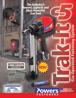
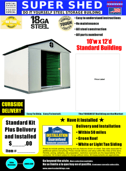
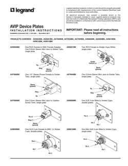
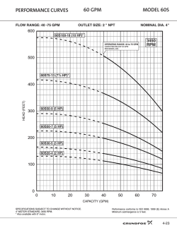

© Copyright 2026