
Low voltage polymer network liquid crystal for infrared spatial light
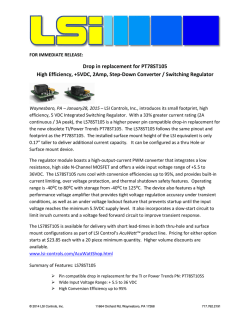
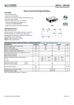
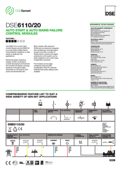
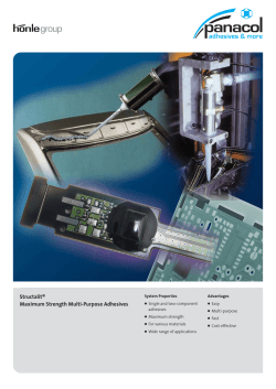
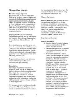
Low voltage polymer network liquid crystal for
infrared spatial light modulators
Fenglin Peng, Daming Xu, Haiwei Chen, and Shin-Tson Wu*
CREOL, The College of Optics and Photonics, University of Central Florida, Orlando, Florida 32816, USA
*
[email protected]
Abstract: We report a low-voltage and fast-response polymer network
liquid crystal (PNLC) infrared phase modulator. To optimize device
performance, we propose a physical model to understand the curing
temperature effect on average domain size. Good agreement between model
and experiment is obtained. By optimizing the UV curing temperature and
employing a large dielectric anisotropy LC host, we have lowered the 2π
phase change voltage to 22.8V at 1.55μm wavelength while keeping
response time at about 1 ms. Widespread application of such a PNLC
integrated into a high resolution liquid-crystal-on-silicon (LCoS) for
infrared spatial light modulator is foreseeable.
©2015 Optical Society of America
OCIS codes: (230.3720) Liquid-crystal devices; (120.5060) Phase modulation; (160.3710)
Liquid crystals.
References and links
1.
2.
3.
4.
5.
6.
7.
8.
9.
10.
11.
12.
13.
14.
15.
16.
17.
18.
19.
U. Efron, Spatial Light Modulator Technology: Materials, Devices, and Applications (Marcel Dekker, 1994).
S. Quirin, D. S. Peterka, and R. Yuste, “Instantaneous three-dimensional sensing using spatial light modulator
illumination with extended depth of field imaging,” Opt. Express 21(13), 16007–16021 (2013).
H. Ren and S.-T. Wu, Introduction to Adaptive Lenses (Wiley, 2012).
F. Feng, I. H. White, and T. D. Wilkinson, “Free space communications with beam steering a two-electrode
tapered laser diode using liquid-crystal SLM,” J. Lightwave Technol. 31(12), 2001–2007 (2013).
F. Peng, Y. Chen, S.-T. Wu, S. Tripathi, and R. J. Twieg, “Low loss liquid crystals for infrared applications,”
Liq. Cryst. 41(11), 1545–1552 (2014).
R. A. Forber, A. Au, U. Efron, K. Sayyah, S. T. Wu, and G. C. Goldsmith II, “Dynamic IR scene projection
using the Hughes liquid crystal light valve,” Proc. SPIE 1665, 259–273 (1992).
F. Peng, H. Chen, S. Tripathi, R. J. Twieg, and S.-T. Wu, “Fast-response infrared phase modulator based on
polymer network liquid crystal,” Opt. Mater. Express 5(2), 265–273 (2015).
B. M. Moslehi, K. K. Chau, and J. W. Goodman, “Optical amplifiers and liquid-crystal shutters applied to
electrically reconfigurable fiber optic signal processors,” Opt. Eng. 32(5), 974–981 (1993).
G. Zhu, B. Y. Wei, L. Y. Shi, X. W. Lin, W. Hu, Z. D. Huang, and Y. Q. Lu, “A fast response variable optical
attenuator based on blue phase liquid crystal,” Opt. Express 21(5), 5332–5337 (2013).
J. Sun, S.-T. Wu, and Y. Haseba, “A low voltage submillisecond-response polymer network liquid crystal spatial
light modulator,” Appl. Phys. Lett. 104(2), 023305 (2014).
S.-T. Wu, “Birefringence dispersions of liquid crystals,” Phys. Rev. A 33(2), 1270–1274 (1986).
J. Sun and S. T. Wu, “Recent advances in polymer network liquid crystal spatial light modulators,” J. Polym.
Sci., Part B, Polym. Phys. 52(3), 183–192 (2014).
J. Yan, Y. Chen, S.-T. Wu, S.-H. Liu, K.-L. Cheng, and J.-W. Shiu, “Dynamic response of a polymer-stabilized
blue-phase liquid crystal,” J. Appl. Phys. 111(6), 063103 (2012).
I. Dierking, “Polymer network–stabilized liquid crystals,” Adv. Mater. 12(3), 167–181 (2000).
D. Xu, J. Yan, J. Yuan, F. Peng, Y. Chen, and S.-T. Wu, “Electro-optic response of polymer-stabilized blue
phase liquid crystals,” Appl. Phys. Lett. 105(1), 011119 (2014).
Y.-H. Fan, Y.-H. Lin, H. Ren, S. Gauza, and S.-T. Wu, “Fast-response and scattering-free polymer network
liquid crystals for infrared light modulators,” Appl. Phys. Lett. 84(8), 1233–1235 (2004).
S. A. Serati, X. Xia, O. Mughal, and A. Linnenberger, “High-resolution phase-only spatial light modulators with
submillisecond response,” Proc. SPIE 5106, 138–145 (2003).
J. Sun, Y. Chen, and S.-T. Wu, “Submillisecond-response and scattering-free infrared liquid crystal phase
modulators,” Opt. Express 20(18), 20124–20129 (2012).
F. Du and S.-T. Wu, “Curing temperature effects on liquid crystal gels,” Appl. Phys. Lett. 83(7), 1310–1312
(2003).
#226549 - $15.00 USD
© 2015 OSA
Received 7 Nov 2014; revised 14 Jan 2015; accepted 15 Jan 2015; published 28 Jan 2015
9 Feb 2015 | Vol. 23, No. 3 | DOI:10.1364/OE.23.002361 | OPTICS EXPRESS 2361
20. F. Du, S. Gauza, and S.-T. Wu, “Influence of curing temperature and high birefringence on the properties of
polymerstabilized liquid crystals,” Opt. Express 11(22), 2891–2896 (2003).
21. D.-K. Yang, Y. Cui, H. Nemati, X. Zhou, and A. Moheghi, “Modeling aligning effect of polymer network in
polymer stabilized nematic liquid crystals,” J. Appl. Phys. 114(24), 243515 (2013).
22. S.-T. Wu and C.-S. Wu, “Experimental confirmation of the Osipov-Terentjev theory on the viscosity of nematic
liquid crystals,” Phys. Rev. A 42(4), 2219–2227 (1990).
23. H. Kneppe, F. Schneider, and N. K. Sharma, “Rotational viscosity γ1 of nematic liquid crystals,” J. Chem. Phys.
77(6), 3203–3208 (1982).
24. H. Chen, F. Peng, Z. Luo, D. Xu, S.-T. Wu, M.-C. Li, S.-L. Lee, and W.-C. Tsai, “High performance liquid
crystal displays with a low dielectric constant material,” Opt. Mater. Express 4(11), 2262–2273 (2014).
25. S.-T. Wu, A. M. Lackner, and U. Efron, “Optimal operation temperature of liquid crystal modulators,” Appl.
Opt. 26(16), 3441–3445 (1987).
26. J. Yan, Y. Chen, S.-T. Wu, and X. Song, “Figure of merit of polymer-stabilized blue phase liquid crystals,” J.
Disp. Technol. 9(1), 24–29 (2013).
1. Introduction
Liquid crystal (LC) spatial light modulators (SLMs) [1] have been widely used in adaptive
optics [2], adaptive lens [3], laser beam control [4–7] and fiber-optic communication [8, 9].
Low operation voltage for 2π phase change (V2π) and fast response time are critical
requirements for these applications. Most SLMs using a nematic LC has advantage in low
V2π, however, its response time is relatively slow (50-100 ms). Polymer network liquid crystal
(PNLC) is a promising candidate for SLM because of its simple fabrication method, submillisecond response time, and large phase change (δ) which is governed by:
δ = 2π d Δn / λ ,
(1)
where d is the cell gap, ∆n is the LC birefringence, and λ is the operation wavelength. Two
major technical challenges of PNLC are: 1) its V2π is relatively high, originating from strong
anchoring force exerted from submicron polymer network domain sizes, and 2) light
scattering. Recently, Sun et al [10] demonstrated a PNLC with V2π = 23V at λ = 514nm with a
significantly suppressed light scattering (~3%). Although a 3% scattering seems low, when
several devices are cascaded together the total optical loss is still significant.
As the wavelength increases, the LC birefringence gradually decreases and then saturates
in the infrared (IR) region [11]. As a result, the available phase change decreases. From Sun’s
multi-layer model, the on-state voltage of a PNLC device is proportional to the cell gap as
[10]:
Von ∝
πd
d1
K11
,
ε 0 Δε
(2)
here d1 is the average domain size, K11 is the splay elastic constant, ε0 is the electric
permittivity and ∆ε is the dielectric anisotropy. Therefore, for a given domain size and LC
material, V2π increases as the cell gap or wavelength increases. Unlike a nematic liquid
crystal, the LC molecules in a PNLC device are partitioned into numerous submicron
domains. The restoring force on the deformed LC directors is dominated by the anchoring
force of polymer network [12]. However, the anchoring force is not uniform over the LC
medium [13]. The LC molecules closer to polymer network would experience a stronger
anchoring force than those in the center. Therefore, they will rotate by different angles when
an electric field is applied. Moreover, stronger anchoring force helps restore the LC
molecules with faster response time. Therefore when the applied voltage is high enough, the
LC molecules with weaker anchoring force will be reoriented to a larger angle and it takes
longer time to restore back. As a result, multiple decay processes take place [14, 15] and
response time increases. Fan et al [16] have demonstrated a PNLC light modulator at λ =
1.55µm with V2π≈60V in a reflective mode. However, the spatial phase profile is not uniform
due to employing a non-mesogenic monomer (M1) [12]. On the other hand, the commonly
#226549 - $15.00 USD
© 2015 OSA
Received 7 Nov 2014; revised 14 Jan 2015; accepted 15 Jan 2015; published 28 Jan 2015
9 Feb 2015 | Vol. 23, No. 3 | DOI:10.1364/OE.23.002361 | OPTICS EXPRESS 2362
used high resolution liquid-crystal-on-silicon (LCoS) has a maximum voltage of 24V [17].
Therefore, to integrate infrared PNLC with LCoS for widespread applications, there is a need
to develop a PNLC with V2π<24V, while keeping fast response time and spatially uniform
phase profile.
In this paper, we demonstrate a reflective-mode PNLC phase modulator with V2π = 22.6V
at λ = 1.55µm and response time τ≈1.13ms. To achieve such a low operation voltage while
keeping fast response time in the IR region, we optimized UV curing condition and LC host.
First, we investigated the curing temperature effects on domain size, which plays a critical
role affecting the operation voltage and response time. A physical model was proposed to
describe this correlation. Excellent agreement between model and experiment is obtained.
Besides, the performance of a PNLC is heavily affected by the properties of the LC host.
Therefore, we define a figure of merit (FoM), which is independent of device structure and
domain size, for comparing the LC hosts. The temperature effect on FoM was also studied.
For a given LC host, there is an optimal operation temperature for a PNLC, where FoM has a
maximum value.
2. Sample preparation
To fabricate PNLCs, we prepared a precursor by mixing 92.5wt% of LC host (JC-BP07N,
JNC), with 7.0 wt% of monomer (RM257, Merck) and 0.5 wt% of photo-initiator (BAPO,
Genocure). Here, we used RM257 (a LC monomer) to maintain good alignment and obtain
uniform phase profile. We filled the precursor into homogeneous LC cells (indium tin oxide
glass substrates). The cell gap was controlled at ~11.8µm. The clearing point (Tc) of JCBP07N is 87°C. If the curing temperature is close or higher than Tc, then the LC molecules
will not align well with the rubbing directions, resulting in severe light scattering after
polymerization. Thus, during UV curing process we controlled the curing temperature for
each cell from 0°C to 70°C separately. Here, a UV light-emitting diode (LED) lamp (λ =
385nm, Intensity is 300 mW/cm2) was employed and the exposure time was one hour.
3. Curing temperature effect
To characterize the electro-optic properties of each PNLC cell, we measured its voltagedependent transmittance (VT) with a laser beam at λ = 1.55μm. The PNLC cells were
sandwiched between two crossed polarizers, with the rubbing direction at 45° to the
polarizer’s transmission axis. The phase change of reflective mode is twice of transmissive
mode due to the doubled optical path.
Fig. 1. Curing temperature dependent threshold voltage of PNLCs: dots stand for measured
data and red line for fitting curve with Eq. (9).
Figure 1 depicts the measured threshold voltage (Vth) of PNLCs cured at different
temperatures. As the curing temperature increases from 0°C to 70°C, Vth decreases from
#226549 - $15.00 USD
© 2015 OSA
Received 7 Nov 2014; revised 14 Jan 2015; accepted 15 Jan 2015; published 28 Jan 2015
9 Feb 2015 | Vol. 23, No. 3 | DOI:10.1364/OE.23.002361 | OPTICS EXPRESS 2363
25.0V to 10.9V. This is because the LC viscosity decreases exponentially with increased
curing temperature, which accelerates the polymer diffusion rate. Thus, the domain size is
inversely proportional to the LC viscosity [18]. Therefore, higher curing temperature
produces coarser polymer network [19, 20] and generates PNLC with larger average domain
size. The anchoring force provided by polymer network becomes weaker with a larger
domain size and coarser polymer network, and thus the driving voltage decreases [21].
Du et al [19, 20] explored the curing temperature effects on LC gels, but no quantitative
model was developed to correlate the curing temperature with domain size. Based on the
multi-layer model, free relaxation time (τ) is insensitive to the cell gap and it is governed by
the average domain size (d1) as:
τ = γ 1d12 / ( K11π 2 ),
(3)
where γ1 is the rotational viscosity, K11 is the splay elastic constant and d1 is the average
domain size. Therefore, the average domain size at each curing temperature can be obtained
by measuring the free relaxation time of the PNLC. To measure the free relaxation time, we
applied a small bias voltage to each PNLC sample to get a small initial phase change δ0 in
order to satisfy the small angle approximation [22]. At t = 0, the voltage was removed
instantaneously and optical signal recorded by a photodiode detector. The time dependent
phase relaxation curve can be expressed as:
δ (t) = δ 0 exp(−2 t/ τ ).
(4)
By fitting with Eq. (4), the free relaxation time for each PNLC sample can be extracted. Next,
we calculated the average domain size based on Eq. (3).
Fig. 2. Curing temperature dependent average domain size of PNLCs: dots stand for the
measured data and red line for fitting curve with Eq. (8).
Figure 2 depicts the domain size obtained at each curing temperature. As the curing
temperature increases from 0°C to 70°C, the average domain size increases from 130nm to
280nm because of the increased monomer diffusion rate. The increased domain size has pros
and cons. On the positive side, it weakens the anchoring force, leading to a lower operation
voltage. But on the negative side, the response time increases. From Fig. 2, even the curing
temperature reaches 70°C the domain size is only 280nm, which is still much smaller than the
infrared wavelength (λ = 1.55µm). Thus, light scattering remains negligible. Based on StokesEinstein theory, the domain size is inversely proportional to the viscosity [18]. Thus, the
domain size (d1) can be expressed as:
d12 ~
#226549 - $15.00 USD
© 2015 OSA
k BTt
,
3πη R
(5)
Received 7 Nov 2014; revised 14 Jan 2015; accepted 15 Jan 2015; published 28 Jan 2015
9 Feb 2015 | Vol. 23, No. 3 | DOI:10.1364/OE.23.002361 | OPTICS EXPRESS 2364
here kB is the Boltzmann constant, T is the Kelvin temperature, η is the flow viscosity, R is the
radius of the particles, and t is the time interval. Among these parameters, R and t are
independent of temperature. The flow viscosity is much smaller than rotational viscosity but
has similar temperature dependence [23, 24]:
η ~ S ⋅ exp( Eb / k BT ),
(6)
S = (1 − T/ Tc ) β ,
(7)
here S is the order parameter, Eb is the fitting parameter related to activation energy, Tc is the
clearing point, and β is a material constant. By substituting Eq. (6) into Eq. (5), the curing
temperature dependent domain size can be expressed as:
d1 = A ⋅
T exp(− E b / k B T)
,
(1 − T / Tc ) β
(8)
where A is a fitting parameter. We fitted average domain size d1 at various curing
temperatures with Eq. (8). Good agreement is obtained as shown in Fig. 2. The fitting
parameters are A = 106.9 nm / K and Eb = 131.3 meV. The material constant β = 0.16 is
obtained independently by fitting the temperature dependent birefringence data. The melting
point of JC-BP07N is Tc = 87°C. The adjustable parameter A is governed by the viscosity of
LC host, monomer concentration, and UV dosage. A LC with higher rotational viscosity
contributes to smaller domain size [18]. In the meantime, higher monomer concentration and
UV dosage contribute to a smaller average domain size [14]. Besides, the threshold voltage
(Vth) is inversely proportional to d1. Thus, we fitted the threshold voltage at each curing
temperature with following equation:
Vth =
(1 − T/ Tc ) β exp(E b / k B T)
B
=B
,
d1
T
(9)
here B is a fitting parameter, while Tc and β maintain unchanged. As shown in Fig. 1, good
agreement is obtained with B = 26.5 V K . and Eb = 137.5 meV. The obtained activation
energy is within 5% of that fitted with Eq. (8), which confirms the validity of our physical
model between domain size and curing temperature. Since both operation voltage and
response time are determined by the domain size, this physical model provides useful
guidelines to optimize the domain size by controlling curing temperature.
When the curing temperature is further increased to 73°C, V2π drops to 22.8V as Fig. 3(a)
shows, which is within the reach of LCoS. Figure 3(b) shows the measured decay time of a
reflective PNLC cell whose initial biased voltage is 22.8V. Similar to measuring the free
relaxation time, the biased voltage was removed instantaneously at t = 0. The measured phase
decay time from 100% to 10% is 1.13ms, which is 2X faster than that previously reported
[16].
#226549 - $15.00 USD
© 2015 OSA
Received 7 Nov 2014; revised 14 Jan 2015; accepted 15 Jan 2015; published 28 Jan 2015
9 Feb 2015 | Vol. 23, No. 3 | DOI:10.1364/OE.23.002361 | OPTICS EXPRESS 2365
Fig. 3. (a) Voltage-dependent phase change at λ = 1.55μm for a PNLC cured at 73°C with V2π
= 22.8V. (b) Measured phase decay time of the PNLC sample. Black line is experimental data
and red line is fitting result with Eq. (4) and δo = 2π.
Table 1. Physical properties and figure of merits of five LC hosts used in PNLCs.
LC mixtures
Δn
(λ = 633nm)
Δε
γ1
(Pa·s)
HTG135200 (HCCH)
JC-BP07N (JNC)
E44 (Merck)
BL038 (Merck)
BP1 (HCCH)
0.21
0.17
0.24
0.25
0.15
86
302
16
16
50
1.20
3.88
0.33
0.56
1.52
FoM1
(ΔεΔn2/γ1)
(Pa·s)−1
3.16
1.82
2.79
1.79
0.74
FoM2
(Δε/γ1)
(Pa·s)−1
71.67
77.84
48.48
28.57
32.89
3. Figure of merit (FoM) of LC host
The overall performance of a PNLC device is governed by three key parameters: 1) 2π phase
change, 2) low operation voltage, and 3) fast response time. The phase change requirement is
determined by Eq. (1). The ∆n employed in a PNLC device is slightly smaller than that of the
LC host because the polymer network makes no contribution. The on-state voltage and
response time are described by Eqs. (2) and (3), respectively. Therefore, besides the cell gap
and domain size, the physical properties of LC host also play a key role in determining the
overall performance of PNLC. As discussed above, the domain size can be controlled by the
monomer concentration and curing temperature. If a certain phase change (say δ = 2π) is
required, then the cell gap should satisfy following simple condition:
d = λ / Δn.
(10)
By substituting Eq. (10) into Eq. (2), the correlation between V2π and Δn is found:
V2π ~
λ
Δnd1
K11
.
ε 0 Δε
(11)
To balance the overall performance, response time needs to be considered as well [25]. To
eliminate the effect of domain size, based on Eqs. (3) and (11), here we define a Figure of
Merit (FoM1) to evaluate the properties of LC host as:
FoM 1 = 1/ (V22π τ ) ~ ΔεΔn 2 / γ 1 .
(12)
Therefore, the FoM1 is independent of the domain size and elastic constant (K11). From Eq.
(12), LC host with a large Δε, Δn and small γ1 is preferred for PNLC devices. If the cell gap is
fixed, then we take the product of Eq. (3) and the square of Eq. (2) directly, and FoM1 could
be simplified to:
#226549 - $15.00 USD
© 2015 OSA
Received 7 Nov 2014; revised 14 Jan 2015; accepted 15 Jan 2015; published 28 Jan 2015
9 Feb 2015 | Vol. 23, No. 3 | DOI:10.1364/OE.23.002361 | OPTICS EXPRESS 2366
FoM 2 = 1/ (V22π τ ) ~ Δε / γ 1 .
(13)
Table 1 lists several LC hosts we employed for making PNLC devices. HTG 135200 (HCCH,
China) shows the highest FoM1 among those LC mixtures due to its relatively high
birefringence and dielectric anisotropy. However, if the cell gap is fixed, then JC-BP07N
shows the best performance due to its extremely large Δε. Thus, for λ = 1.55µm and d =
11.8µm, JC-BP07N is a good host. When the curing temperature is increased to 73°C, the
operation voltage is reduced to below 24V. However, JC-BP07 has a lower FoM2 than
HTG135200 because of its lower birefringence. From Eqs. (12) and (13), FoM1 and FoM2 are
sensitive to the temperature because birefringence, rotational viscosity and dielectric
anisotropy are also temperature dependent [11, 22, 26]:
Δn = Δn0 (1 − T/ Tc ) β ,
(14)
γ 1 ~ S ⋅ exp( Eb / k BT ),
(15)
Δε = C ⋅ S exp(U/ k BT ),
(16)
where ∆n0 is the extrapolated birefringence at T = 0K, C is a fitting parameter, and U is a
parameter related to the dipole moment. By combining these equations, the temperature
dependency of FoM1 is derived as:
FoM 1 = D ⋅
(1 − T/ Tc ) 2 β
,
exp((E a − U) / k B T)
(17)
here D is a fitting parameter. As shown in Fig. 4, dots stand for the measured data and red line
for the fitting results with Eq. (17) for JC-BP07N. Good agreement is obtained with following
fitting parameters: D = 8.98 × 10⁶, U = 207.8 meV, Ea = 575.3 meV, β = 0.16 and Tc = 87°C.
β, Ea and U are obtained by fitting Eqs. (14), (15) and (16) respectively. Since the polymer
network (i.e. domain size) and device structure are independent of operating temperature, the
temperature dependent performance of PNLC is basically determined by the employed LC
host only. At room temperature, the FoM1 is ~4.79 μm2/s and it increases to 11.35 μm2/s at
60þC. As the temperature increases, viscosity decreases more quickly than birefringence and
dielectric anisotropy initially, resulting in an increased FoM1. As T approaches Tc, Δn
decreases more quickly than γ1, leading to a sharply declined FoM1. On the other hand, the
temperature dependent FoM2 is expressed as:
FoM 2 ~ exp((U − Ea ) / k B T).
(18)
FoM2 increases as the temperature gets higher, because the fitting parameter U is usually
smaller than the activation energy Ea for LC hosts [26]. Therefore, for a given PNLC an
optimal operation temperature (Top) exists which gives the maximum FoM1. To derive the
optimal temperature, we set d (FoM) / dT = 0 and find that
Topt = Tc −
2 β k BTc2
.
Ea − U
(19)
By substituting the fitting parameters of JC-BP07N, we found Top = 77.4°C, or the optimal
operation temperature is about 10°C lower than the clearing point. At Top, FoM1 has a peak
value even though the operation voltage would increase due to the decreased Δε. Therefore,
the device can be operated at Top if fast response time is the primary requirement.
#226549 - $15.00 USD
© 2015 OSA
Received 7 Nov 2014; revised 14 Jan 2015; accepted 15 Jan 2015; published 28 Jan 2015
9 Feb 2015 | Vol. 23, No. 3 | DOI:10.1364/OE.23.002361 | OPTICS EXPRESS 2367
Fig. 4. Temperature dependent FoM1 for JC-BP07N at λ = 633nm: dots stand for the measured
data and red line for fitting curve with Eq. (17)
4. Conclusion
We have developed a physical model to correlate the curing temperature and domain size.
The proposed equation fits very well with the experimental data, which also provides a good
approach to optimize the curing temperature. Besides, we defined a FoM to compare the
performance of LC hosts for PNLC devices. For a given LC host, there is an optimal
temperature for achieving maximum FoM. Therefore, by increasing curing temperature to
73°C and employing a LC host with large ∆ε, we have achieved V2π = 22.8V in reflective
mode operating at infrared region (λ = 1.55μm).With keeping uniform phase profile, the
response time is only half of previous reported. Such a low operation voltage will allow
PNLC to be integrated in a high resolution LCoS for next-generation SLM applications.
Acknowledgment
The authors are indebted to AFOSR for the financial supports under contract No. FA9550-141-0279.
#226549 - $15.00 USD
© 2015 OSA
Received 7 Nov 2014; revised 14 Jan 2015; accepted 15 Jan 2015; published 28 Jan 2015
9 Feb 2015 | Vol. 23, No. 3 | DOI:10.1364/OE.23.002361 | OPTICS EXPRESS 2368
© Copyright 2026