
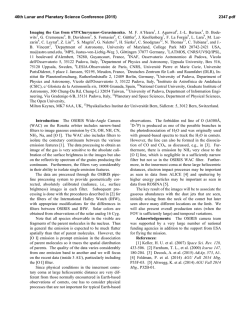
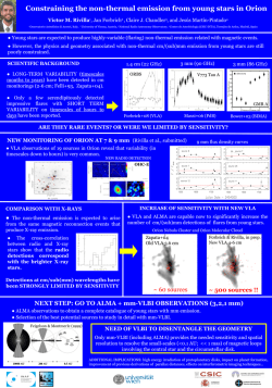
Electronic properties of phosphorus-doped triode-type
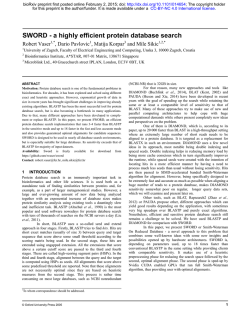
Materials Chemistry and Physics 72 (2001) 210–213 Electronic properties of phosphorus-doped triode-type diamond field emission arrays Chia-Fu Chen∗ , Chia-Lun Tsai, Chien-Liang Lin Department of Materials Science and Engineering, National Chiao Tung University, 1001 Ta-Hsueh Road, Hsinchu 30050, Taiwan Abstract In this work, we present a novel scheme that involves a new fabrication process of gate structure metal–insulator–semiconductor (MIS) diode using IC technology. We use a bias-assisted microwave plasma chemical vapor deposition (BAMPCVD) system to synthesize P-doped and B-doped diamond. Based on our experimental results, it showed dendrite-like diamond with non-doped and nanotube-like diamond with B- or P- doping. Doping phosphorus or boron can enhance its electric characteristic by reducing the turn-on voltage and enhancing the emission current density. The turn-on voltage of non-doped, B-doped and P-doped is 15, 8 and 5 V, respectively. The field emission current (Ia ) of non-doped, B-doped and P-doped is 4 A (at 45 V), 76 A (at 77 V) and 322 A (at 120 V), respectively. © 2001 Elsevier Science B.V. All rights reserved. Keywords: Field emission; SEM; CVD 1. Introduction Field emission display (FED) is evolving as one of the promising techniques for the future generation of flat panel displays. Indeed, there have been several efforts to make the metal-tip emitter and silicon-tip array field emission devices. However, the electrical field required for triggering the field emission of these devices is rather high. Moreover, their performance rapidly degrades due to the thermal effect [1]. In contrast, diamond has recently been considered as the most promising cold cathode material for field emission devices due to its several important advantages. Investigations involving field emission from CVD diamond have largely focused on fabricating diamond films, while several others have fabricated diamond-clad silicon FEAs [2], the electron emission from CVD-grown diamond films [3], and the silicon tips with diamond particles at their apex end regions [4]. Furthermore, several other investigations have fabricated pyramidal-shape diamond field emitters [5]. However, this process is too long, thereby decreasing the quality of the diamond films and ultimately weakening the diamond films to the extent that it is difficult to treat by the last process. Hence, in this paper, we fabricate a miniature-size and simple process triode diamond FEAs. Many factors affect the performance of field emitter arrays including the shape and work function of emission materials, distance between tip and gate, and the environ∗ Corresponding author. Tel./fax: +886-3-5731898. E-mail address: [email protected] (C.-F. Chen). mental vacuum condition. In this study, a metal–insulator– semiconductor (MIS) diode using IC technology is presented. Using a bias-assisted microwave plasma chemical vapor deposition (BAMPCVD) system synthesized P-doped and B-doped completes this process. 2. Experimental The similar fabrication process of this MIS diode and diamond deposition procedure have been previously presented in [6]. First, we design the MIS diode structure and fabricated the MIS diode by semiconductor process technologies. Starting substrates were mirror-polish n-type, (1 0 0) oriented wafer with a resistivity of 4.5–5.5 cm−1 . After fabricating the MIS diode, specimens were put in the BAMPCVD system to deposit diamond with various deposition parameters. The reactive gases used in deposition were the conventional mixture of CH4 –H2 with trimethylphosphite (P(OCH3 )3 ) or trimethylborate (B(OCH3 )3 ) as the dopant source. All the experiments of the diamond deposition use two-step depositions. The first step is determined to nucleation process: the flow rates of CH4 /H2 and deposition time remain constant at 10/200 sccm and 30 min, respectively. On the other hand, the second step is the growth process and total deposition normally lasts for 60 min. While processing the deposition, the specimens were applied a negative bias voltage of 130 V. 0254-0584/01/$ – see front matter © 2001 Elsevier Science B.V. All rights reserved. PII: S 0 2 5 4 - 0 5 8 4 ( 0 1 ) 0 0 4 3 8 - 2 C.-F. Chen et al. / Materials Chemistry and Physics 72 (2001) 210–213 The scanning electron microscopy (SEM) was used to observe the morphology of a triode-shaped diamond FEAs with a gated structure, and secondary ion mass spectrometry (SIMS) was used to identify the surface composition of the diamond emitters. Micro-Raman spectroscopy was used to identify the quality of these different diamond emitters, and I–V measuring system to obtain their electrical characterization. The field emission properties of the triode diamond FEAs were measured using a triode technique [6]. 3. Results and discussions 3.1. SEM Fig. 1 displays SEM photographs of the boron- and phosphorus-doped diamond emitters, where the doping sources are trimethylborate and trimethylphosphite. The branches disappear when boron or phosphorus is added, while the shape resembles a nanotube-like diamond. We suspect that the boron or phosphorus doping cannot be formed similarly to the dendrite-like diamond because of the following reasons. The lower growth rate resulting from Fig. 1. The SEM photographs of (a) non-doped (b) P-doped and (c) B-doped diamond. 211 the higher amounts of trimethylborate or trimethylphosphite may be related to the reduction of the CH4 flow rate and the diamond growth precursors in the H2 –CH4 feed gas. Trimethylborate or trimethylphosphite is a CH3 -rich compound that decomposes in plasma to produce an equal quantity of CH3 radicals to balance the carbon source in the gas phase. The lower growth rates of heavily or slightly doped films are most likely owing to the oxygen content involved in the trimethylborate or trimethylphosphite molecules. There were more oxygen atoms than phosphorus atoms in the doping source. This may be related to the etching of non-diamond carbon from the growing surface resulting in a lower growth rate. The same effects may also occur when adding O2 to the CH4 –CO2 gas mixture [7]. 3.2. The doping source concentration effect Fig. 2 shows the depth profile of silicon-doped phosphorus and boron. The primary beam is O2 with 8 keV and 140 nA. The rafter areas are 225 × 225 m2 . Fig. 3 displays the morphologies of different concentrations of phosphorus doping. Fig. 2. SIMS depth profiles of (a) phosphorus-doped and (b) boron-doped diamond (note: only qualitative analysis). 212 C.-F. Chen et al. / Materials Chemistry and Physics 72 (2001) 210–213 Fig. 4. The Raman spectra of non-doped, P-doped and B-doped diamond. centered at 1580 cm−1 increased with the trimethylborate or trimethylphosphite concentration. P(OCH3 )3 doping during the process increase the methyl radical (CH3 –) because the doping source are CH3 -rich compound. Thus the etching rate declined, while the quantity of amorphous carbon or graphite increased in the resultant films. The Raman shift can be accounted for by the lattice strain caused by the boron or phosphorus doping. 3.4. Electrical property Fig. 3. The SEM photographs of P-doped diamond samples with different concentration of doping P(OCH3 )3 : (a) 2; (b) 1; (c) 0.5 sccm. Many investigations have conferred that phosphorus will lower the diamond growth rate in H2 –CH4 mixtures [7,8]. The shape of emitters resembles a diamond-tip with many tiny tips around it when the phosphorus concentration is 2 sccm. The average height and the density of the emitter are smaller than non-doped diamond emitters. Decreasing the concentration to 1 and 0.5 sccm enhances both the intensity and the average height of diamond emitters. Diamond emitters have some invisible branches on their bodies at 0.5 sccm. Lowering the phosphorus concentration transforms the diamond emitters’ shape from a nanotube-like to a dendrite-like diamond and increases the amount of visible emitters. There is no obvious change in the boron concentration, however, the upper limitation of concentration is 2 sccm since both the intensity and morphology is altered when the concentration exceeds 2 sccm. In this study, there are much significant difference with respect to the change of doping P or B. Fig. 5 exhibits the field emission current (Ia ) vs. gate voltage of non-doped dendrite-like diamond, B-doped and P-doped nanotube-like diamond, respectively. The field emission current (Ia ) of non-doped, B-doped and P-doped diamond are 4 A (at Vgc = 33 V), 76 A (at Vgc = 77 V) and 322 A (at Vgc = 120 V), respectively. In other words, the field emission density is about 13, 242 and 1026 mA cm−2 for non-doped, B-doped and P-doped diamond, respectively. This means that doping B or P can enhance electron property by increasing emission current and current density. Comparing to the emission current, those of the B-doped and P-doped are 20 and 80 times, respectively, larger than that of non-doped diamond emitters. From our results, we find that P-doped diamond emitters have better field emission characteriza- 3.3. Micro-Raman spectroscopy Fig. 4 compares Raman spectra of the non-doped, Pdoped and B-doped diamond. According to this figure, the quantity of graphite increased and the diamond qualities decreased because the intensity of the broad peak Fig. 5. Ia –Vgc curve and emission current density of different diamond FEAs. C.-F. Chen et al. / Materials Chemistry and Physics 72 (2001) 210–213 tion than that of B-doped. This is possibly due to higher electron conductivity and defect density for the P-doped ones. Simply speaking, B-doped only has impurity effect for electron property. The electron emitting characteristics of these three diamonds were further evaluated by using Fowler–Nordheim plot. The threshold voltage (Vth ) changes significantly with non-doped and doping diamond emitter arrays. They are 15, 8 and 5 V at non-doped, B-doped and P-doped diamond emitters, respectively. 3.5. Boron and phosphorus effect From our results, we found that both B-doped and P-doped diamonds have better field emission characterization. From solid-state physics, doping boron or phosphorus will cause its energy bend diagram change by generating donor or acceptor level. They provide more electrons or holes for the material. This increases its total conductivity and net flux. If temperature is not high, we can see the “impurity range” on its I–V curve. Always this means the impurity effect. Generally speaking, doping boron or phosphorus supplies more holes or electrons for material. The increment enhances material’s electron characteristics. But based on experimental data, doping phosphorus has better field emission property than doping boron does. We speculate that there may be following two reasons. The one is that doping phosphorus indeed has much more influence than doping boron on conductivity. The other is due to the morphology defect of diamond emitter. P-doped has much defect and makes its electrons have more opportunity to be extracted. Some also reported this is because of forming the space charge layer due to ionized donors [9]. 3.6. sp2 /sp3 effect Combining the Raman discussion and results of the previous section, the field emission characterization of the diamond can be enhanced by increasing sp2 content. The emission current is significantly improved and turn-on voltage is drastically reduced. We speculated this phenomenon is due to the following reasons: 1. Defect-induced band owing to sp2 content. This proposes that the defect-induced energy band created by sp2 content is responsible for the field emission enhancement. A defect-induced energy band can be induced throughout the energy gap of diamond due to the presence of a wild variety of structural defects created as a consequence of sp2 particles. The formation of these defect bands raise the Fermi level toward the conduction band, and thus reduce the work function for enhancing field emission. Simply speaking, the work function has been changed after doping. 2. Increase in field enhancement factor owing to sp2 -diamond-sp2 (MIM) microstructures. This proposed that isolated conducting sp2 particles in diamond form cas- 213 caded MIM microstructures, which enhance the field enhancement factor. Field enhancement factor β was affected by many ways. Geometrical parameters of the device structure, such as the gate opening diameter, tip radius, emitter high and position of the tip with respect to the center of the gate thickness and morphology of emitters. Here, we state that adding the phosphorus or boron changes their structures and also affects the field enhancement factor β. 4. Conclusion In this work, we demonstrate the feasibility of the new fabrication process of triode diamond FEAs, which contain small gate aperture and shallow depth of field cells. Doping either phosphorus or boron can enhance their electron characteristic by reducing the turn-on voltage and enhancing emission the current density. The turn-on voltage of non-doped, B-doped and P-doped samples are 15, 8 and 5 V, respectively. The emission current of B-doped and P-doped are about 20 and 80 times, respectively, larger than non-doped diamond emitters. The morphology from dendrite-like diamond to nanotube-like diamond is due to doping phosphorus or boron. Because our doping sources are trimethylphosphite and trimethylborate contained O2 atom. This will reduce diamond growth rate when they are decomposed in plasma during process. Selective area deposition (SAD) of diamond on the silicon substrates was successfully achieved by using Pt-gated layer as nucleation inhibitor. New morphologies of diamond emitters including dendrite-like and nanotube-like diamond are formed. Acknowledgements The authors would like to thank the National Science Council of the Republic of China for financially supporting this research under Contract No. NSC 89-2216-E-009-022. References [1] J.S. Lee, K.S. Liu, I.N. Lin, Appl. Phys. Lett. 71 (4) (1997) 554. [2] N.J. She, A Study of Application and Characterization of Diamond Thin Films on Field Emitter Arrays, Master’s Thesis, Chiao Tung University, Hsinchu, Taiwan, 1996. [3] W.H. Huang, Study of Selective Growth of Diamond Film for Field Emitter Arrays, Master’s Thesis, Chiao Tung University, Hsinchu, Taiwan, 1996. [4] E.I. Givargizov, V. Zhirnov, et al., Appl. Surf. Sci. 87–88 (1995) 24. [5] E.S. Baik, D.R. Jeon, Y.J. Baik, Diamond Relat. Mater. 8 (1999) 89. [6] C.F. Chen, H.C. Wang, H.C. Hsieh, Jpn. J. Appl. Phys. 39 (2000) 1880. [7] C.F. Chen, T.M. Hang, S.H. Cheng, J. Appl. Phys. 74 (1993) 4483. [8] S.N. Schauer, J.R. Flemish, M.I. Landstrass, M.A. Piano, Appl. Phys. Lett. 64 (9) (1994) 1094. [9] K. Kuriyama, C. Kimura, S. Koizumi, M. Kamo, T. Sugino, J. Vac. Technol. B 17 (2) (1999) 723.


© Copyright 2026