
Engineering Guide
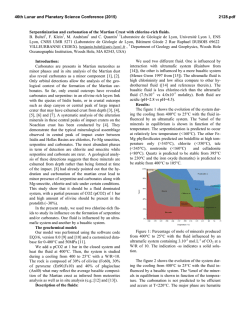
Dynalene MV engineering guide Copyright © 2014 Dynalene, Inc. All Rights Reserved. EG Engineering Guide | 0 Contents Product Overview 2 Freezing & Melting Point 2 Flash Point 2 Vapor Pressure 2 General Properties 3 Odor Evaluation 3 Packaging & Shipping 3 Shelf Life 4 Metals Compatibility 4 Gasket & Polymer Compatibility 4 General Installation Guidelines 4 Retrofitting for Dynalene MV 6 Preparing New Systems Using Dynalene MV 7 Ongoing Sample Analysis 7 Basic Heat Transfer Fluid System Design 8 Dynalene MV Properties: SI Units 9 Dynalene MV Properties: English Units 10 Toxicology Report 11 Product Disclaimer 11 Locations & Contact Information 11 Copyright © 2014 Dynalene, Inc. All Rights Reserved. MV Engineering Guide | 1 Product Overview Dynalene MV is an environmentally acceptable low temperature heat transfer fluid. It was developed to extend the “low end” operating temperature range far below the boundaries of most competitive brands. Dynalene MV heat transfer fluid has a limited toxicity; it is also biodegradable and CFC free. Dynalene MV has a recommended use temperature range of –170°F to 325°F. It is essential that all personnel handling this product review and understand this manual and the Dynalene MV material safety data sheet (MSDS). Please contact Dynalene for more information. Freezing & Melting Point Dynalene MV has a freezing and melting point below -129°C (-200°F), allowing broader application to systems using cryogenic liquids or ultra-low temperature mechanical refrigeration equipment. This results in greater tolerance when lowering the surface film temperature. Flash Point Dynalene MV heat transfer fluid has a closed cup flash point of 53°C (127°F), and an open cup flash point of >60°C (141°F). Like other hydrocarbon based heat transfer fluids, Dynalene MV and its vapors may ignite if released into the environment by being exposed to hot surfaces, sparks, open flames, or any other source of ignition. Vapor Pressure Vapor pressure is a critical property to be considered when calculating Net Positive Suction Head (NPSH), a major factor in the sizing of fluid handling equipment. “Air tight” containment is recommended to limit the escape of Dynalene MV vapors. See Table 1 below for vapor pressures of Dynalene MV at various temperatures. Table 1. Vapor pressure of Dynalene MV. Temperature, °C (°F) 0 (32) Vapor Pressure, mmHG (psi) 1.0 (0.019) 25 (77) 1.9 (0.037) 100 (212) 63.7 (1.232) Copyright © 2014 Dynalene, Inc. All Rights Reserved. MV Engineering Guide | 2 General Properties General properties of Dynalene MV can be found in Table 2. Table 2. General properties of Dynalene MV. Property Composition Hydrocarbon blend Appearance Translucent, light yellow Odor Mild orange odor Operating range -115°C to 163°C (-175°F to 325°F) Freezing point <-129°C (<-200°F) Boiling point 176°C (348°F) Flash point (closed) 53°C (127°F) Flash point (open) 61°C (142°F) Fire point 64°C (147°F) Autoignition temp. 388°C (730°F) Critical temp. 387°C (729°F) Critical pressure 34 bar (33.6 atm) Molecular weight 135 g/mol Dielectric constant 2.3 Odor Evaluation Dynalene MV heat transfer fluid is produced using hydrocarbon liquid blends. Proper safety procedures must be practiced at all times. Dynalene MV has a mild hydrocarbon/orange odor that will become evident in the surrounding area if the fluid or its vapors are released into the environment. Do not handle or expose personnel to Dynalene MV liquid without reviewing and understanding the Material Safety Data Sheet (MSDS). Always handle the fluid in well ventilated areas; the area should be free from sparks, open flames, or smoking. Use respiratory protection consistent with the recommendations in the MSDS. Packaging & Shipping Dynalene MV heat transfer fluid is available in 5 gallon pails, 55 gallon drums, and bulk quantities. Dynalene MV heat transfer fluid has a shipping hazard classification of number 3 in the USA. Dynalene MV is listed as a Combustible or Flammable Liquid when transported by highway or rail, but must be listed as a Flammable Liquid when shipped by air or waterway. Copyright © 2014 Dynalene, Inc. All Rights Reserved. MV Engineering Guide | 3 Shelf Life Dynalene MV heat transfer fluid will remain stable for a period of at least one year if: (1) It is stored in the original unopened pail or drum (2) The storage area is a dry environment below 100°F. Partially full pails and drums should be blanketed with an inert gas such as nitrogen to eliminate oxygen from the container head space. Metals Compatibility Dynalene MV heat transfer fluid has an acceptable compatibility rating when installed in vapor tight systems constructed within the temperature, pressure, and structural limitations of the following metals: • Aluminum • Brass • Bronze (All) • Carbon Steel • Cast Steel • Copper • Copper Nickel (All) • Hastelloy (All) • Inconel • Incoloy 825 • Monel • Nickel • Stainless Steel (All) • Stainless Steel Clad • Tantalum Gasket & Polymer Compatibility Dynalene MV heat transfer fluid has an acceptable compatibility when used within the temperature and pressure limitation of the following polymers or gasketing materials: • Acetal • Aramid Fiber • Chemraz (FFKM) • Epoxy • Fluorocarbon (FILM) • Fluoroelastomer • Glass Fiber • Gylon Style 3500, 3504, & 3510 • Kalrez • • • • • • • • PEEK Polytetrafluoro-ethylene Teflon (All) Teflon Encapsulated Silicone Teflon Encapsulated Viton Telfon Impregnated Fiberglass Kel-F (CTE) Viton Resin Impregnated Carbon Graphite General Installation Guidelines The following recommendations are provided to assist the designer/user in achieving proper installation. 1 Understanding the engineering guide Prior to purchasing any Dynalene MV, review and understand all of the information contained in this manual—especially the sections titled ‘Retrofitting for Dynalene MV’ and ‘Preparing New Systems Using Dynalene MV’. Only qualified personnel with expertise in safe handling of potentially hazardous liquids (in compliance with local, state, and federal regulations) should be involved with work processes of this nature. Copyright © 2014 Dynalene, Inc. All Rights Reserved. MV Engineering Guide | 4 2 Moisture content Moisture content within Dynalene MV in system operation is recommended to be less than 100 parts per million (.01% H20 in Dynalene MV). The freezing point, viscosity, and heat transfer coefficient of Dynalene MV may be adversely affected if moisture content is above recommended levels. Moisture is heavier than Dynalene MV and will drop out of the solution at approximately 400 to 500 PPM, depending upon liquid temperature. In low temperature applications, excessive moisture in Dynalene MV will impair heat transfer; this may result in frozen heat exchangers, seized regulators, etc. Desiccating Dynalene MV as shown in Figure 1 (page 8) is one recommended method of removing moisture from Dynalene MV. If a moisture analysis is required for your Dynalene MV, contact Dynalene at 1-877-244-5525 or email [email protected]. 3 Presence of oxygen Limit the presence of oxygen within the wetted areas of a piped system. An inert gas, such as nitrogen, is the favored substitute to air in the vapor space. A replenishable supply of air or oxygen in contact with Dynalene MV will promote premature fluid degradation. The basic fluid system sketch illustrated in Figure 1 (page 8), is an example of a typical Dynalene MV heat transfer fluid system using an inert gas purge as a method of excluding oxygen. The inert gas pressure regulator BPV set point should be approximately 50% higher than the maximum Dynalene MV vapor pressure value anticipated with the system. 4 Maximum surface temperature Surface temperature of heat source components should not exceed 400°F (204°C). Fluid velocity should maintain a minimum of 8 feet per second (2.44 meters per second). 5 Using electric resistance heaters Electric resistance heaters used in Dynalene MV heat transfer fluid applications are recommended to use a maximum watt density of 28 watts per square inch. If you require a review on the heating equipment you have considered, consult Dynalene. 6 Pump equipment To eliminate cavitation when using Dynalene MV near its boiling point, apply sufficient inert gas (nitrogen, argon) pressure in the head space. 7 Available ancillary equipment Dynalene desiccation canisters are available upon request. 8 Safety dos and don’ts Handling Dynalene MV in the drum: ensure drums containing Dynalene MV are properly grounded and keep all drums away from sources of ignition, power tools, heat, smoking, and sparks. Pumping Dynalene MV into the system: only pump Dynalene MV in well-ventilated areas and wear the required personnel protective equipment as recommended in the Dynalene MV MSDS. System maintenance: prior to cutting or welding systems that use Dynalene MV, ensure all residual Dynalene MV and its vapor are removed from the system. This can be accomplished by fully purging and evacuating all fluid and vapors using the methods described in ‘Retrofitting for Dynalene MV.’ Draining Dynalene MV from a system: when draining Dynalene MV from a system, be sure to use sealed connections on all pipes, tubes, and containment to minimize leakage of vapor and mists. For precautionary measures, all systems using Dynalene MV should be properly grounded. Copyright © 2014 Dynalene, Inc. All Rights Reserved. MV Engineering Guide | 5 Retrofitting for Dynalene MV Dynalene MV heat transfer fluid is an excellent replacement for the fluid chemistries listed below: • CFC Refrigerant • Chlorinated Solvent • HFC Refrigerant • Hydrocarbon Based • Alcohols (methanol, ethanol, isopropanol) • Perfluorocarbon • Silicone • d-Limonene Once the original liquid is removed, systems may retain small amounts of residual liquid in low lying areas such as piping traps, inverted coils, pump housings, valve housings, drain pipes, etc. The residual liquids must be removed for Dynalene MV to function properly as specified. The following recommendations are provided by Dynalene to assist the installer or end user in achieving a successful retrofit: To determine the actual volume of the heat transfer fluid needed in the retrofit, there are two methods that can be used: 1. If the system drawing is available, then perform a volume calculation based on size and length of piping, reservoirs, heat exchangers, pumps, and all other wetted components. 2. Drain the existing heat transfer fluid from the system and measure the volume removed. To account for the residual fluid left after draining, follow the steps in the next section. To remove residual fluids, purge the existing system with compressed air or an inert gas such as nitrogen (for combustible liquids). For best results, purge intermittently with disruptions to zero pressure once every two minutes. For example, purge with pressure for one minute, and then disrupt purge to zero pressure in system for the next minute. Continue this process for several minutes until there is no more fluid leaving the system. Measure the volume of the residual fluid and add to the volume of the drained fluid to determine the total heat transfer fluid volume. Combine the residual fluid and drained fluid into a vented container and dispose accordingly. Other methods to remove residual liquid: 1 System evacuation Systems evacuation is performed by creating a vacuum, usually more than 20" Hg, within the existing system containing the residual liquid at room temperature. As the vacuum within the system increases, the boiling point of the residual liquid will decrease and evaporate. The intent is to evaporate the residual liquid completely by lowering its boiling point to below the internal temperature of the system. 2 Air and inert gas evaporation Liquid evaporation using air or an inert gas may be another feasible method of removing residual liquid from an existing piped system. This is performed by allowing an adequate volume of dry compressed air or inert gas, such as nitrogen, to enter the existing system and flow through the inner piped wetted areas, including low points. The intent is to evaporate the residual liquid and allow the effluent to exit the piped system at a point that is generally opposite the inlet air or inert gas connection. Compressed air or inert gas is recommended to have a dew point lower than –95°F, and sufficiently below the evaporation point of liquid being removed. 3 Dilution Dilution of residual fluid can be performed in conjunction with the system evacuation or evaporation methods. Dilution of the residual fluid can be performed by selecting a dilution solvent that is miscible with the residual fluid and has a high vapor pressure. After diluting the residual fluid with the solvent, drain and follow either step 1 or 2. Copyright © 2014 Dynalene, Inc. All Rights Reserved. MV Engineering Guide | 6 Preparing New Systems Using Dynalene MV The following recommendations are provided to assist the installer or end user in achieving a proper installation: 1 Flush the system Systems intending to use Dynalene MV heat transfer fluid should be properly flushed clean after installing components such as pipes, valves, pumps, etc. Materials from welding operations, excess pipe joint compound, oils, and other unwanted contaminants must be removed completely prior to installing Dynalene MV. Using a dilution solvent that is completely miscible with the contaminants generated during an installation is one recommended method of flushing a system clean. 2 Perform a moisture analysis After installing Dynalene MV and circulating for at least one hour, Dynalene recommends removing a fluid sample for moisture analysis. A pre-labeled sample kit will be provided upon request. Dynalene will perform a moisture analysis and report the necessary actions or corrections that need to be taken. This is to ensure the moisture content is within the recommended level, especially when operating Dynalene MV below 35°F. 3 Install line filtration Dynalene MV should remain free of debris throughout the operational life of the liquid. An appropriately sized in-line strainer using a perforation size (1⁄32") or less, is recommended to be installed directly in the flow of fluid to allow the most effective particulate removal from the fluid. Providing filtration down to approximately 5 microns, combined with an in-line strainer as a prefilter, is the best method of keeping Dynalene MV particulate free. Use of bypass and slip-stream filtration is also acceptable. Ongoing Fluid Maintenance Dynalene can provide a pre-labeled sample kit upon request, which includes the sample bottle, an instruction page, and an MSDS sheet. Dynalene offers the first sample analysis free of charge. For best results: 1. 2. 3. Take a fluid sample when the system is at room temperature to prevent moisture from contaminating the Dynalene MV. Before filling up the sample bottle, allow the fluid to flow out for a few seconds into another container to clear any debris. Leave about one inch of airspace from the top of the sample bottle to minimize leakage. After closing the cap, secure by wrapping electrical tape around it several times. It is best to take a fluid sample while the fluid is circulating. Copyright © 2014 Dynalene, Inc. All Rights Reserved. MV Engineering Guide | 7 Basic heat transfer fluid system design Figure 1. Basic Dynalene MV heat transfer system. Copyright © 2014 Dynalene, Inc. All Rights Reserved. MV Engineering Guide | 8 Dynalene MV Properties: SI Units Properties of Dynalene MV vs. temperature in SI units are given in Table 3. Table 3. Properties of Dynalene MV. Temp Viscosity Thermal Cond. Specific Heat Density °C mPa·s W/m·K kJ/kg·K kg/m3 -112 215.3 0.165 1.330 948 -100 46.4 0.162 1.373 938 -90 19.9 0.159 1.408 931 -80 10.7 0.157 1.443 923 -70 6.66 0.155 1.479 915 -60 4.58 0.152 1.514 907 -50 3.38 0.150 1.549 900 -40 2.63 0.148 1.584 892 -30 2.13 0.145 1.620 884 -20 1.78 0.143 1.655 876 -10 1.53 0.140 1.690 869 0 1.34 0.138 1.726 861 10 1.19 0.136 1.761 853 20 1.07 0.133 1.796 845 30 0.97 0.131 1.831 838 40 0.90 0.128 1.867 830 50 0.83 0.126 1.902 822 60 0.78 0.124 1.937 815 70 0.73 0.121 1.973 807 80 0.69 0.119 2.008 799 90 0.65 0.117 2.043 791 100 0.62 0.114 2.078 784 110 0.59 0.112 2.114 776 120 0.57 0.109 2.149 768 130 0.55 0.107 2.184 760 140 0.53 0.105 2.219 753 150 0.51 0.102 2.255 745 163 0.49 0.099 2.301 735 Copyright © 2014 Dynalene, Inc. All Rights Reserved. MV Engineering Guide | 9 Dynalene MV Properties: English Units Properties of Dynalene MV vs. temperature in English units are given in Table 4. Table 4. Properties of Dynalene MV. Temp Viscosity Thermal Cond. Specific Heat Density °F cP BTU/hr·ft·°F BTU/lb·°F lb/ft3 -170 218.0 0.095 0.318 59.2 -160 97.1 0.094 0.322 58.9 -140 30.3 0.093 0.332 58.4 -120 13.7 0.091 0.341 57.8 -100 7.64 0.090 0.350 57.3 -80 4.92 0.088 0.360 56.8 -60 3.47 0.087 0.369 56.2 -40 2.62 0.085 0.379 55.7 -20 2.08 0.084 0.388 55.2 0 1.72 0.082 0.397 54.6 20 1.46 0.081 0.407 54.1 40 1.26 0.079 0.416 53.5 60 1.12 0.078 0.425 53.0 80 1.00 0.076 0.435 52.5 100 0.91 0.074 0.444 51.9 120 0.84 0.073 0.453 51.4 140 0.77 0.071 0.463 50.9 160 0.72 0.070 0.472 50.3 180 0.68 0.068 0.482 49.8 200 0.64 0.067 0.491 49.3 220 0.61 0.065 0.500 48.7 240 0.58 0.064 0.510 48.2 260 0.56 0.062 0.519 47.6 280 0.53 0.061 0.528 47.1 300 0.51 0.059 0.538 46.6 320 0.50 0.058 0.547 46.0 325 0.49 0.057 0.549 45.9 Copyright © 2014 Dynalene, Inc. All Rights Reserved. MV Engineering Guide | 10 Toxicological Report For complete toxicological information regarding Dynalene MV, consult the MSDS. The MSDS for Dynalene MV should be understood prior to use. Product Disclaimer The information contained in this entire publication is presented in good faith at “no charge” and is believed to be correct as of the date indicated no representations or warranties are made as to its completeness or accuracy. The information listed is supplied upon the condition that the persons receiving it will make their own determination as to its suitability for their purposes prior to use. In no event will the seller be responsible for damages of any nature whatsoever resulting from the use of, or reliance upon, this information or the product to which this information refers. Nothing contained on this page is to be construed as a recommendation to use the product, process, equipment or formulation in conflict with any patent. No representation or warranty, expressed or implied, is made that the use of this product will not infringe any patent. No representations or warranties, either expressed or implies, of merchantability, fitness for a particular purpose or for any other nature are made with respect to the information, or the product to which the information refers. Locations & Contact Information Corporate Headquarters Dynalene, Inc. 5250 West Coplay Road Whitehall, Pennsylvania 18052 Phone: 610-262-9686 / 1-877-244-5525 Fax: 610-262-7437 Email: [email protected] Website: www.dynalene.com Midwest Location 648 Bennett Road Elk Grove Village, IL 60007 1-855-216-7639 Copyright © 2014 Dynalene, Inc. All Rights Reserved. MV Engineering Guide | 11
© Copyright 2026