
THLR rangecard user manual
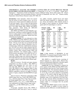
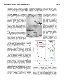
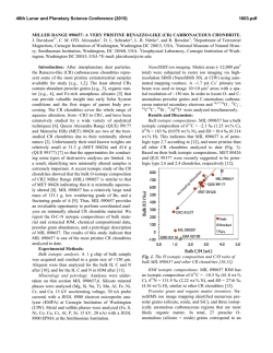
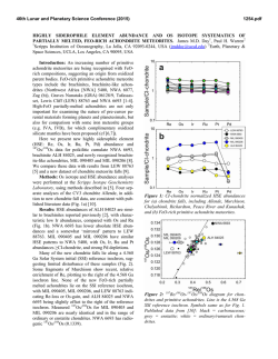
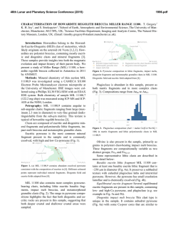
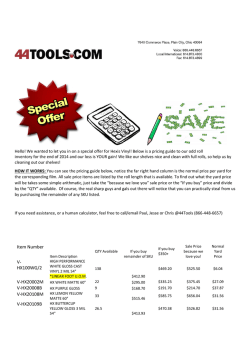
THLR RANGECARD
Instruction pdf (ver 1)
1
M/SEC
1:50K
METER
2
3
4
5
7.5
10
15
20
MIRAGE
cm 7
0
KM/H
4
2
2
5
2
MPH
5
10
C
B
+3
+4
+4
+5
GAP
+5
TH
SHOOTING HIGHER/ OVER VISIBLE WIND
ADD + CLICKS TO WIND CORRECTION
D
F
G
TARGET RANGE/ SCOPE TURRET/ DESCRIPTION
H
4
I
1
22
•
2
0.75
RETICLE HOLDOVER PLAN
10 12 14 16 18
5
8
+
6
A
+2
+3
26
30
1
0.50
0
0
MOA/100M
½
¾
MILLING SHOULDER
▼
50˚
.64
+
•
▼
0.9
•
1
WIND
LOG
•
40˚
LEAD
.76
LIGHT
•
•
+
34
cm
0.25
PRESS/
DA/ ALT
TEMP
30˚
.86
20˚
V0
.93
10˚
.98
0˚
▼
+1 MIL
1 MIL
0.8 MIL
0.6 MIL
0.4 MIL
= SHOOT!
=
475 M
=
595 M
=
792 M
= 1187 M
THLR.NO
THLR RANGECARD
Main features
4
6
MPH
2
5
3
4
5
7.5
10
15
20
5
A
10
C
B
4
+2
+3
+3
+4
3
+4
+5
GAP
+5
TH
SHOOTING HIGHER/ OVER VISIBLE WIND
ADD + CLICKS TO WIND CORRECTION
D
F
G
TARGET RANGE/ SCOPE TURRET/ DESCRIPTION
H
5
4
I
1
22
6
2
0.75
•
RETICLE HOLDOVER PLAN
8 10 12 14 16 18
5
2
2
+
2
2
KM/H
MIRAGE
cm 7
0
1
1
M/SEC
1:50K
METER
26
30
1
0.50
7
.64
▼
50˚
•
8
+
½
¾
11
0.9
•
1
WIND
LOG
•
40˚
.76
LIGHT
•
9
•
+
0
0
MOA/100M
▼
34
cm
0.25
TEMP
30˚
10
PRESS/
DA/ ALT
.86
20˚
V0
.93
10˚
.98
MILLING SHOULDER
LEAD
+1 MIL
1 MIL
0.8 MIL
0.6 MIL
0.4 MIL
0˚ ▼
= SHOOT!
= 475 M
= 595 M
= 792 M
= 1187 M
12
THLR.NO
1. Ruler. Measure range on map, centimeters
or MOA group size.
2. Mirage angle/ wind velocity illustration
3. Windage corrections for shooting high over
visible wind
4. Columns for sketch legend
5. Reticle holdover plan
6. Sketch area with vanishing point
7. Tool for measuring shooting angle
8. Factors for crosswind component OR
shooter error log
9. Additional weather log entry points
10. Colums for weather/ ammunition data
11. Aid for leads on moving targets
12. Aid for using the reticle MIL scale for range
estimation.
THLR RANGECARD
Abstract
«Fullfill the most important functions of traditional military sketches. Move decisions away from the
timeframe of target ID – shot. Add a few safety pins against «brain-freeze». Make it packable,
lightweight, weather resistant and semi-expendable. Add log functions to build habit of packing/
using the rangecard. Add training support by patterning shooter error.»
THLR RANGECARD
1.
1:50K
METER
1:50K
METER
1:50K
METER
0
2
4
4
8 10 12 14 16 18
4
2
2
4
2
1
1
cm
0.25
34
0
MOA/100M
0.50
30
cm
0.75
26
0.25
34
34
0
MOA/100M
0.50
30
30
0.25
0.75
26
26
0.50
1
22
22
22
0.75
Measure range on maps scaled 1:50000. Read top-down,
example from
to
reads range approximately 1925
meters. It is presumed you know how to use a map.
2.
Centimeter ruler. Read bottom – up, example from
reads 5 centimeters.
3.
Ruler for measuring your groups size in MOA (measuring
the spread of your bullet holes). This ruler is scaled for 100
meters (European range use) and makes it easier to
participate in the great internet debate. Read bottom – up,
example from
to
reads 0,5 MOA group size.
to
5
6
8 10 12 14 16 18
5
6
8 10 12 14 16 18
5
6
1
1
4
4
2
1
2
2
2
cm
0
0
2
1.
cm 7
3
cm 7
2
cm 7
1
0
MOA/100M
THLR RANGECARD
2. Mirage angle illustration
MIRAGE M/SEC
1
2
MPH 2
3
5
4
5
10
• Use this when you can see mirage through
your optics
• Compare the angle you see in your optics with
the angle on the Rangecard illustration.
• Read off the assosciated wind velocity.
• This wind is the crosswind component, it can
be used directly for ballistic input.
Example:
You see that the mirage angle is slightly more than 45 degrees angle.
The closest match is this circle 3
Use value 3 m/sec to read off your ballistic table
Note:
Reading mirage can be very difficult. Look for the straightest lines in your field of view, that is often the easiest spot to
determine the mirage angle.
Reading mirage is not nearly as exact as reading the wind. The values on the Snipertool is easy to use, but after 600 meters
you will find that you are slightly overcompansating on the windage.
When the mirage runs level, the crosswind component is at least 5 m/sec and you have a huge chance of error. We
recommend reading wind over mirage when it approaches horisontal angle.
THLR RANGECARD
3. Windage corrections for shooting high over visible wind
•
SHOOTING HIGHER/ OVER VISIBLE WIND
ADD + CLICKS TO WIND CORRECTION
+2
+3
+3
+4
+4
+5
GAP
+5
•
•
•
•
•
These numbers just acknowledge that wind velocity increase with elevation above ground. These
numbers are not a ballistic calculation, just a simplified indicator to help build your own
experience.
Base your windcall on visual indicators and adjust your scope windage for that.
In cases where you are shooting the bullet far over the visual indicators you used for the windcall,
add some clicks on the scope.
Where you can see the wind along the bullets trajectory DO NOT add these clicks.
Use the first column (+2/+3) when you shoot the bullet approximately 10 meters above your visual
indicator for the windcall. The last column when your «very far» above your visual indicator.
«GAP» is used when you have a gap that will compress and blow a very strong wind across your
bullet trajectory. It is a wild guess and basically says «good luck with that shot!»
Note:
The illustration shows a grossly simplified model where
we extrapolated the wind velocity along a bullet trajectory
shot across a valley.
These numbers are calculated from elevation alone and
does NOT represent the true spotwind, they merely
illustrate a principle.
If the shooter can see the wind only at his location (3
m/sec), it is fairly evident that he will undercompensate on
his windage.
In the illustrated example the bullet travels «very far»
above the visual indicators and the shooter adds +4/+5
clicks to at least pull the bullet in the right direction.
If the shooter sees visual indicators along the bullet
trajectory, no such corrections is added regardsless of
how far above ground the bullet travels.
THLR RANGECARD
4. Columns for sketch legend
•
A
B
C
House 410 410m / 17 UP 410m / 17 UP
F
G
TARGET RANGE/ SCOPE TURRET/ DESCRIPTION
16 UP
H
•
D
I
•
•
In rangecard mode, the letters A-I refers to a
point on the target sketch (see feature 6). The
letter «E» means bad luck and is not included.
In example A the point on the sketch is named
«house» and ranged to «410» in order to have
a communication reference point.
Example B simply states range «410m» and it
requires «17 UP» on the scope elevation (or
reticle holdover) to accurately shoot a target in
point B.
Example C is the rangecard used in log mode.
We have a at «410m» and the ballistic program
suggested «17up» on the scope elevation to
shoot this target. Test shooting revealed that a
center hit on the target only needed «16 up».
Note:
Example C is one of our favorite uses of this feature. When verifying your
trajectory, pre-plan all your targets and write in the suggestions of the ballistic
program. Log the actual elevation setting directly below. It makes for a very
efficient shooting sessions and gives you structured, quality notes for your
ballistic afterwork. We always verify our rifle trajectories this way, we never
trust ballistic programs without verifications. We always click the scope to
record accurate settings and not perceived scope-holdovers.
THLR RANGECARD
5 Reticle holdover plan
B
A
C
D
RETICLE HOLDOVER PLAN
+
•
•
•
•
•
The letters A,B,C,D corresponds to points A,B,C,D found in the «Columns for
sketch legend» (feature 4) and the same A,B,C,D found in the target sketch
(feature 6).
The points in the target sketch refers to targets or significant points. You
sometimes need to shoot your target inside a very small timeframe – this will
exclude the task of clicking your scope turret.
Usually a scope setting other than your zero is more useful when wathing an
area. Example: If your primary target area is range 400 to 450 meters away,
then leaving the scope zeroed for 100 meters is just stupid. You set it to 425 in
order to have the shortest possible response time to targets appearing here.
If a fleeting target suddenly appears a longer range, a quick shot by holding
over with the scope reticle can be difficult. Your holdover data is referenced to
your normal zero. Your options are using holdovers with reduced accuracy or
using time (and possibly not getting the shot off in time) to click the scope.
If you pre-plan and plot these scenarios, you can have an effetive scope setting
and at the same time have quick, accurate holdovers. A target in area C can be
accurately shot with holdover .
THLR RANGECARD
6 Sketch area
The sketch area (feature 6) works closely together with the
columns for sketch legend (feature 4) and reticle holdover
plan (feature 5).
We assume you have been taught to do sketches and
coordinate your reference points.
House 410
450 (LOW)
B
C
D
Road 540
Rock 480
450 (TOP)
F
G
TARGET RANGE/ SCOPE TURRET/ DESCRIPTION
HOLD
H
Trench 810
65 UP
+
A
I
C
D
D•
A
B
C
In this example the shooter have made a simple (but
sufficient for orientation) target sketch, plotted four significant
points (A, B, C, D) and pre-planned how to quickly shoot
targets in these areas.
For targets at A and B the shooter will simply aim and shoot
as his scope is pre-set to 450. If a very small target is
presented, he can correct by aiming (LOW) or (TOP) on the
target.
For targets at C he will simply hold the reticle over as
indicated by position C in the Reticle holdover plan.
For target D he will click the scope if time permits, if not he
will use holdover D.
THLR RANGECARD
7 Tool for measuring shooting angle
50˚
.64
40˚
.76
Aim across top
30˚
.86
20˚
.93
10˚
.98
0˚ ▼
• This scale is for measuring your angle
when shooting uphill or downhill.
• Aim at your target across the top of the
card.
• Gravity will pull the carry string down
across the scale.
• Read off degrees if you use a precalculated ballistic table.
• Read off consine if you calculate via
Riflemans Rule or similar.
Example:
We aim at the target across the top of the card.
Picture shows downhill. Aim opposite direction if
uphill.
Gravity pulls the carry string down.
Read off the scale. In this example just shy of 35°.
(The illustration shows the THLR Snipertool. The function is identical on THLR
Rangecard.)
THLR RANGECARD
Main features
4
6
MPH
2
5
3
4
5
7.5
10
15
20
5
A
10
C
B
4
+2
+3
+3
+4
3
+4
+5
GAP
+5
TH
SHOOTING HIGHER/ OVER VISIBLE WIND
ADD + CLICKS TO WIND CORRECTION
D
F
G
TARGET RANGE/ SCOPE TURRET/ DESCRIPTION
H
5
4
I
1
22
6
2
0.75
•
RETICLE HOLDOVER PLAN
8 10 12 14 16 18
5
2
2
+
2
2
KM/H
MIRAGE
cm 7
0
1
1
M/SEC
1:50K
METER
26
30
1
0.50
7
.64
▼
50˚
•
8
+
½
¾
11
0.9
•
1
WIND
LOG
•
40˚
.76
LIGHT
•
9
•
+
0
0
MOA/100M
▼
34
cm
0.25
TEMP
30˚
10
PRESS/
DA/ ALT
.86
20˚
V0
.93
10˚
.98
MILLING SHOULDER
LEAD
+1 MIL
1 MIL
0.8 MIL
0.6 MIL
0.4 MIL
0˚ ▼
= SHOOT!
= 475 M
= 595 M
= 792 M
= 1187 M
12
THLR.NO
1. Ruler. Measure range on map, centimeters
or MOA group size.
2. Mirage angle/ wind velocity illustration
3. Windage corrections for shooting high over
visible wind
4. Columns for sketch legend
5. Reticle holdover plan
6. Sketch area with vanishing point
7. Tool for measuring shooting angle
8. Factors for crosswind component OR
shooter error log
9. Additional weather log entry points
10. Colums for weather/ ammunition data
11. Aid for leads on moving targets
12. Aid for using the reticle MIL scale for range
estimation.
THLR RANGECARD
8 Factors for crosswind component OR shooter error log
0
½
¾
▼
+
•
•
▼
0.9
•
1
WIND
LOG
•
If used for finding the crosswind components, do
this:
• Determine wind velocity
• Determine wind angle
• Multiply wind velocity with wind angle
• The result is crosswind component. Crosswind
component is the effective wind that moves
your bullet impact.
Example:
You determine wind to be 4 m/sec (you see the vegetation starts
to lie down). Next determine the wind angle relative to your
shooting direction (pyramid).
4 m/sec by approximately ¾ value is 3 m/sec. 3 m/sec is the
value you use to read data from your rangecard.
Note:
We say «approximately» because wind direction have a normal
variation that is invisible to the shooter. Therefore it is perfectly ok
to round off values to easy numbers. We have put in more
accurate decimal numbers for reference… good luck using those!
THLR RANGECARD
8 Factors for crosswind component OR shooter error log
0
½
¾
▼
+
•
•
▼
0.9
•
1
WIND
LOG
•
If used for finding the shooter error, do this:
• Plot the shots that do not strike intended POI,
regardless of range or target type.
• With time a pattern will build and you will see
systematic and occasional errors.
• By focusing your training effort, it is easier to
reach new performance levels.
Example:
This shooter has most of his misses striking down towards the left. Occasionally he sends a few
shots down left and even up left.
By analyzing the pattern, we can guess the shooter will have best effect by focusing on not pulling
the trigger or the grip towards himself.
His occasional mistakes indicates he every now and then shoves the rifle butt with the shoulder. A
common mistake for fatigued or stressed shooters. Perhaps just an awareness and a mental check
of the shoulder right before the shot will remove this error alltogether.
Up left often indicates an unsettled foreend. Perhaps he just put too much pressure on the bipod
for that one shot? Don’t worry overly much on rare mistakes, just be aware.
THLR RANGECARD
9 Additional weather log entry points
LIGHT
WIND
•
•
A
LIGHT
WIND
•
4
•
B
We personally don’t use these entry points, put other shooters
have different preferences.
Example A shows direction of wind and light logged.
Example B show direction and wind velocity logged
THLR RANGECARD
10 Columns for weather/ ammunition data
•
+
•
TEMP
11
PRESS/
DA/ ALT
992
V0
792
•
These three columns can be filled in in both rangecard or
log mode.
In rangecard mode, fill in air temperature and air
pressure in whatever unit of measure you prefer.
Crosscheck this with ammunition V0 data if you have it,
and make a decision wether or not this will affect your
trajectory.
In log mode, handle your ammunition carefully so the
ammunition V0 from the chronograph can be reliably
linked to the ambient air temperature.
Note:
Shield your thermometer from direct sun exposure or radiation heat from body. Correct air
temperature is measured in a shaded area.
For our personal use, we prefer Kestrel weather handheld weatherstations as they have proven
reliable over time.
THLR RANGECARD
11 Aid for leads on moving targets
+
LEAD
If you must consult this aid, it is fair to presume you will miss your target.
All this feature does is force a mental process and so the shooter makes a few decisions ahead.
It is unlikely to fit your ammunition/ range/ target combination.
THLR RANGECARD
12 Aid for using the reticle MIL scale for range estimation
•
MILLING SHOULDER
+1 MIL
1 MIL
0.8 MIL
0.6 MIL
0.4 MIL
= SHOOT!
=
475 M
=
595 M
=
792 M
= 1187 M
•
•
•
It is presumed you know how to MIL a target with your scope
reticle.
With reliable lasers available, reticle milling for range estimation
is rarely used.
A laser is not always available, and math can be diffucult under
stress.
This coarse scale gives accurate enough range estimation for a
short range shot or a good enough range estimation to place the
shot inside your field of view, making a strike possible to
observe.
Note:
The scale is calculated from a target 475 millimeters wide. Personell targets are rarely facing you
squarely.
THLR RANGECARD
Our prefered marker for the THLR Rangecard is a hardness 2B lead pencil. This is slightly
softer than the common HB and is easier to use in rain.

© Copyright 2026