
Application Development for IBM CICS Web Services
Front cover Application Development for IBM CICS Web Services Overview of Web services in CICS updated for CICS TS 5.2 New Web service performance measurements for CICS TS 5.2 New SOA patterns for CICS TS 5.2 James O’Grady Ian Burnett Jim Harrison San Yong Liu Xue Yong Zhang ibm.com/redbooks International Technical Support Organization Application Development for IBM CICS Web Services January 2015 SG24-7126-02 Note: Before using this information and the product it supports, read the information in “Notices” on page xiii. Third Edition (January 2015) This edition applies to Version 5, Release 2, of IBM CICS Transaction Server. © Copyright International Business Machines Corporation 2015. All rights reserved. Note to U.S. Government Users Restricted Rights -- Use, duplication or disclosure restricted by GSA ADP Schedule Contract with IBM Corp. Contents Notices . . . . . . . . . . . . . . . . . . . . . . . . . . . . . . . . . . . . . . . . . . . . . . . . . . . . . . xiii Trademarks . . . . . . . . . . . . . . . . . . . . . . . . . . . . . . . . . . . . . . . . . . . . . . . . . . . xiv IBM Redbooks promotions . . . . . . . . . . . . . . . . . . . . . . . . . . . . . . . . . . . . . . xv Preface . . . . . . . . . . . . . . . . . . . . . . . . . . . . . . . . . . . . . . . . . . . . . . . . . . . . . xvii Authors . . . . . . . . . . . . . . . . . . . . . . . . . . . . . . . . . . . . . . . . . . . . . . . . . . . . . . xvii Now you can become a published author, too! . . . . . . . . . . . . . . . . . . . . . . . . xix Comments welcome. . . . . . . . . . . . . . . . . . . . . . . . . . . . . . . . . . . . . . . . . . . . . xx Stay connected to IBM Redbooks . . . . . . . . . . . . . . . . . . . . . . . . . . . . . . . . . . xx Summary of changes . . . . . . . . . . . . . . . . . . . . . . . . . . . . . . . . . . . . . . . . . . . xxi January 2015, Third Edition . . . . . . . . . . . . . . . . . . . . . . . . . . . . . . . . . . . . . . . xxi Part 1. Introduction . . . . . . . . . . . . . . . . . . . . . . . . . . . . . . . . . . . . . . . . . . . . . . . . . . . . . . . . . . 1 Chapter 1. Overview of Web services . . . . . . . . . . . . . . . . . . . . . . . . . . . . . . 3 1.1 Introduction . . . . . . . . . . . . . . . . . . . . . . . . . . . . . . . . . . . . . . . . . . . . . . . . . 4 1.2 Service-oriented architecture . . . . . . . . . . . . . . . . . . . . . . . . . . . . . . . . . . . 4 1.2.1 Characteristics . . . . . . . . . . . . . . . . . . . . . . . . . . . . . . . . . . . . . . . . . . 6 1.2.2 Web services versus SOAs. . . . . . . . . . . . . . . . . . . . . . . . . . . . . . . . . 6 1.3 Web services. . . . . . . . . . . . . . . . . . . . . . . . . . . . . . . . . . . . . . . . . . . . . . . . 7 1.3.1 Properties of a Web service . . . . . . . . . . . . . . . . . . . . . . . . . . . . . . . . 7 1.3.2 Core standards . . . . . . . . . . . . . . . . . . . . . . . . . . . . . . . . . . . . . . . . . . 8 1.3.3 Web Services Interoperability group . . . . . . . . . . . . . . . . . . . . . . . . . 11 1.3.4 Additional standards . . . . . . . . . . . . . . . . . . . . . . . . . . . . . . . . . . . . . 11 1.4 IBM WebSphere Service Registry and Repository . . . . . . . . . . . . . . . . . . 13 1.5 SOAP . . . . . . . . . . . . . . . . . . . . . . . . . . . . . . . . . . . . . . . . . . . . . . . . . . . . 13 1.5.1 The envelope . . . . . . . . . . . . . . . . . . . . . . . . . . . . . . . . . . . . . . . . . . 13 1.5.2 Communication styles . . . . . . . . . . . . . . . . . . . . . . . . . . . . . . . . . . . . 18 1.5.3 Encodings . . . . . . . . . . . . . . . . . . . . . . . . . . . . . . . . . . . . . . . . . . . . . 18 1.5.4 Messaging modes . . . . . . . . . . . . . . . . . . . . . . . . . . . . . . . . . . . . . . . 19 1.6 WSDL . . . . . . . . . . . . . . . . . . . . . . . . . . . . . . . . . . . . . . . . . . . . . . . . . . . . 20 1.6.1 WSDL Document . . . . . . . . . . . . . . . . . . . . . . . . . . . . . . . . . . . . . . . 20 1.6.2 WSDL document anatomy . . . . . . . . . . . . . . . . . . . . . . . . . . . . . . . . 21 1.6.3 WSDL definition . . . . . . . . . . . . . . . . . . . . . . . . . . . . . . . . . . . . . . . . 25 1.6.4 WSDL bindings . . . . . . . . . . . . . . . . . . . . . . . . . . . . . . . . . . . . . . . . . 31 Chapter 2. CICS TS implementation of Web services . . . . . . . . . . . . . . . . 35 © Copyright IBM Corp. 2015. All rights reserved. iii 2.1 Support for Web services in CICS TS . . . . . . . . . . . . . . . . . . . . . . . . . . . . 36 2.1.1 Core aspects of Web services in CICS . . . . . . . . . . . . . . . . . . . . . . . 36 2.2 Tools for application deployment. . . . . . . . . . . . . . . . . . . . . . . . . . . . . . . . 38 2.2.1 CICS Web Services Assistant . . . . . . . . . . . . . . . . . . . . . . . . . . . . . . 38 2.2.2 IBM Rational Developer for System z v9.1 . . . . . . . . . . . . . . . . . . . . 39 2.2.3 Other Options . . . . . . . . . . . . . . . . . . . . . . . . . . . . . . . . . . . . . . . . . . 39 2.3 CICS as a service provider . . . . . . . . . . . . . . . . . . . . . . . . . . . . . . . . . . . . 40 2.3.1 Preparing to run a CICS application as a service provider . . . . . . . . 41 2.3.2 Processing the inbound service request . . . . . . . . . . . . . . . . . . . . . . 43 2.4 CICS as a service requester . . . . . . . . . . . . . . . . . . . . . . . . . . . . . . . . . . . 44 2.4.1 Preparing to run a CICS application as a service requester . . . . . . . 45 2.4.2 Processing the outbound service request . . . . . . . . . . . . . . . . . . . . . 46 2.5 The CICS resource definitions . . . . . . . . . . . . . . . . . . . . . . . . . . . . . . . . . 47 2.5.1 URIMAP . . . . . . . . . . . . . . . . . . . . . . . . . . . . . . . . . . . . . . . . . . . . . . 48 2.5.2 PIPELINE . . . . . . . . . . . . . . . . . . . . . . . . . . . . . . . . . . . . . . . . . . . . . 49 2.5.3 WEBSERVICE . . . . . . . . . . . . . . . . . . . . . . . . . . . . . . . . . . . . . . . . . 52 2.5.4 The Web service binding file (WSBind). . . . . . . . . . . . . . . . . . . . . . . 54 2.5.5 SOAPFAULT commands . . . . . . . . . . . . . . . . . . . . . . . . . . . . . . . . . 56 2.5.6 Mapping levels . . . . . . . . . . . . . . . . . . . . . . . . . . . . . . . . . . . . . . . . . 57 2.5.7 Enhancements with CICS TS V3.2 . . . . . . . . . . . . . . . . . . . . . . . . . . 59 2.5.8 Additional enhancements with CICS TS 4.1 . . . . . . . . . . . . . . . . . . . 61 2.5.9 Use of WS-Addressing in CICS TS V4.1 applications . . . . . . . . . . . 63 2.5.10 AXIS2 Provider PIPELINEs in CICS TS V4.2 . . . . . . . . . . . . . . . . . 63 2.5.11 CICS Transaction Server V5.1 makes CONTAINERs easier . . . . . 63 2.5.12 Further enhancements in CICS TS V5.2. . . . . . . . . . . . . . . . . . . . . 63 2.5.13 Comparing releases of CICS Transaction Server . . . . . . . . . . . . . . 64 Chapter 3. Development approaches . . . . . . . . . . . . . . . . . . . . . . . . . . . . . 67 3.1 Introduction . . . . . . . . . . . . . . . . . . . . . . . . . . . . . . . . . . . . . . . . . . . . . . . . 68 3.2 Bottom-up approach . . . . . . . . . . . . . . . . . . . . . . . . . . . . . . . . . . . . . . . . . 69 3.3 Top-down approach . . . . . . . . . . . . . . . . . . . . . . . . . . . . . . . . . . . . . . . . . 71 3.4 Meet-in-the-middle approach . . . . . . . . . . . . . . . . . . . . . . . . . . . . . . . . . . 72 3.5 The advantages of using Rational Developer for System z . . . . . . . . . . . 74 3.6 Web services versus CICS TCP/IP connectivity . . . . . . . . . . . . . . . . . . . . 76 3.7 Conclusions. . . . . . . . . . . . . . . . . . . . . . . . . . . . . . . . . . . . . . . . . . . . . . . . 77 Chapter 4. CICS catalog manager example application . . . . . . . . . . . . . . 79 4.1 Samples for use with CICS Web Services . . . . . . . . . . . . . . . . . . . . . . . . 80 4.2 Introduction to the catalog manager application . . . . . . . . . . . . . . . . . . . . 80 4.3 Installation and setup of the base application . . . . . . . . . . . . . . . . . . . . . . 81 4.3.1 Creating the VSAM data sets . . . . . . . . . . . . . . . . . . . . . . . . . . . . . . 82 4.3.2 Defining the base application to CICS . . . . . . . . . . . . . . . . . . . . . . . 82 4.3.3 Configuring the example application . . . . . . . . . . . . . . . . . . . . . . . . . 83 iv Application Development for IBM CICS Web Services 4.3.4 Configuring code page support . . . . . . . . . . . . . . . . . . . . . . . . . . . . . 86 4.4 Web service support for the example application . . . . . . . . . . . . . . . . . . . 87 4.4.1 The Web client front end . . . . . . . . . . . . . . . . . . . . . . . . . . . . . . . . . . 87 4.4.2 The CICS Web service client front end . . . . . . . . . . . . . . . . . . . . . . . 88 4.4.3 Order dispatch Web services endpoints . . . . . . . . . . . . . . . . . . . . . . 89 4.4.4 Alternative Web service provider configuration . . . . . . . . . . . . . . . . . 89 4.5 Web services setup . . . . . . . . . . . . . . . . . . . . . . . . . . . . . . . . . . . . . . . . . . 90 4.5.1 Creating the zFS directories . . . . . . . . . . . . . . . . . . . . . . . . . . . . . . . 91 4.5.2 Creating the PIPELINE definition . . . . . . . . . . . . . . . . . . . . . . . . . . . 91 4.5.3 Creating a TCPIPSERVICE . . . . . . . . . . . . . . . . . . . . . . . . . . . . . . . 93 4.5.4 Dynamically installing WEBSERVICE and URIMAP resources . . . . 94 4.5.5 Creating the WEBSERVICE resources with RDO . . . . . . . . . . . . . . 97 4.5.6 Creating the URIMAP resources with RDO . . . . . . . . . . . . . . . . . . . 98 4.5.7 Completing the installation . . . . . . . . . . . . . . . . . . . . . . . . . . . . . . . . 99 4.6 Installing the client application. . . . . . . . . . . . . . . . . . . . . . . . . . . . . . . . . . 99 4.6.1 FTP the client application . . . . . . . . . . . . . . . . . . . . . . . . . . . . . . . . 100 4.6.2 Install the client . . . . . . . . . . . . . . . . . . . . . . . . . . . . . . . . . . . . . . . . 100 4.6.3 Start the client . . . . . . . . . . . . . . . . . . . . . . . . . . . . . . . . . . . . . . . . . 105 4.6.4 Testing the client . . . . . . . . . . . . . . . . . . . . . . . . . . . . . . . . . . . . . . . 105 Chapter 5. Rational Developer for System z . . . . . . . . . . . . . . . . . . . . . . . 109 5.1 What is Rational Developer for System z? . . . . . . . . . . . . . . . . . . . . . . . 110 5.2 RDz and CICS application development . . . . . . . . . . . . . . . . . . . . . . . . . 110 5.3 Components of RDz . . . . . . . . . . . . . . . . . . . . . . . . . . . . . . . . . . . . . . . . 110 5.3.1 Workspace . . . . . . . . . . . . . . . . . . . . . . . . . . . . . . . . . . . . . . . . . . . 111 5.3.2 Workbench . . . . . . . . . . . . . . . . . . . . . . . . . . . . . . . . . . . . . . . . . . . 111 5.3.3 Perspective . . . . . . . . . . . . . . . . . . . . . . . . . . . . . . . . . . . . . . . . . . . 112 5.3.4 View . . . . . . . . . . . . . . . . . . . . . . . . . . . . . . . . . . . . . . . . . . . . . . . . 113 5.3.5 Editor. . . . . . . . . . . . . . . . . . . . . . . . . . . . . . . . . . . . . . . . . . . . . . . . 115 5.4 Web services in Rational Developer for System z . . . . . . . . . . . . . . . . . 116 5.5 Writing your first Java program with RDz . . . . . . . . . . . . . . . . . . . . . . . . 117 5.6 Overview of Debugging with RDz . . . . . . . . . . . . . . . . . . . . . . . . . . . . . . 120 5.6.1 Supported languages and environments . . . . . . . . . . . . . . . . . . . . 120 5.6.2 Local and remote debug . . . . . . . . . . . . . . . . . . . . . . . . . . . . . . . . . 121 5.6.3 Basic debugging features and tools . . . . . . . . . . . . . . . . . . . . . . . . 121 5.7 Summary . . . . . . . . . . . . . . . . . . . . . . . . . . . . . . . . . . . . . . . . . . . . . . . . . 123 Chapter 6. Exposing the Catalog Sample CICS application as a Web service . . . . . . . . . . . . . . . . . . . . . . . . . . . . . . . . . . . . . . 125 6.1 Introduction . . . . . . . . . . . . . . . . . . . . . . . . . . . . . . . . . . . . . . . . . . . . . . . 126 6.2 Install the provider mode resources . . . . . . . . . . . . . . . . . . . . . . . . . . . . 128 6.3 Create the provider mode deployment artifacts . . . . . . . . . . . . . . . . . . . 129 6.3.1 Using the CICS Web Services Assistant. . . . . . . . . . . . . . . . . . . . . 130 Contents v 6.3.2 Use Rational Developer for System z . . . . . . . . . . . . . . . . . . . . . . . 136 6.4 Testing the Web service . . . . . . . . . . . . . . . . . . . . . . . . . . . . . . . . . . . . . 146 6.4.1 The Web Services Explorer . . . . . . . . . . . . . . . . . . . . . . . . . . . . . . 147 6.4.2 Generate a client. . . . . . . . . . . . . . . . . . . . . . . . . . . . . . . . . . . . . . . 151 6.5 Publishing WSDL to WebSphere Service Registry and Repository . . . . 155 6.5.1 Use DFHLS2WS for WebSphere Service Registry and Repository in CICS TS V5.2 . . . . . . . . . . . . . . . . . . . . . . . . . . . . . . . . . . . . . . . . . 156 6.5.2 Use DFHWS2LS for WSRR in CICS TS V5.2. . . . . . . . . . . . . . . . . 157 6.5.3 New parameters to support SSL encryption in CICS TS V4.1 and above . . . . . . . . . . . . . . . . . . . . . . . . . . . . . . . . . . . . . . . . . . . . 159 6.6 Writing applications that process the XML directly . . . . . . . . . . . . . . . . . 160 6.6.1 Creating a custom application handler . . . . . . . . . . . . . . . . . . . . . . 160 6.6.2 Creating an XML-ONLY WEBSERVICE . . . . . . . . . . . . . . . . . . . . . 161 Chapter 7. Create a CICS Web service requester application using the catalog sample . . . . . . . . . . . . . . . . . . . . . . . . . . . . . . . . . . . . . 163 7.1 Introduction . . . . . . . . . . . . . . . . . . . . . . . . . . . . . . . . . . . . . . . . . . . . . . . 164 7.2 Create a Web service requester using the CICS Web Services Assistant . . . . . . . . . . . . . . . . . . . . . . . . . . . . . . . . . . . . . 167 7.2.1 Generate the required artifacts . . . . . . . . . . . . . . . . . . . . . . . . . . . . 167 7.2.2 Set up the CICS infrastructure . . . . . . . . . . . . . . . . . . . . . . . . . . . . 170 7.2.3 Test the requester application . . . . . . . . . . . . . . . . . . . . . . . . . . . . . 173 7.3 Creating and testing a Web service hosted in RDz. . . . . . . . . . . . . . . . . 175 7.3.1 Create a Web service skeleton with Rational Application Developer for WebSphere Software . . . . . . . . . . . . . . . . . . . . . . . . . . . . . . . . . . . 176 7.3.2 Implement the WebSphere Application Server Web service . . . . . 180 7.3.3 Test the Web service using Web Services Explorer . . . . . . . . . . . . 182 7.3.4 Test the Web service using the CICS sample application . . . . . . . 184 7.4 Client mode URIMAPs . . . . . . . . . . . . . . . . . . . . . . . . . . . . . . . . . . . . . . 186 7.4.1 Ease of maintenance and portability . . . . . . . . . . . . . . . . . . . . . . . . 186 7.4.2 Control over outbound SSL configuration . . . . . . . . . . . . . . . . . . . . 187 7.4.3 Outbound connection pooling . . . . . . . . . . . . . . . . . . . . . . . . . . . . . 187 Chapter 8. Componentization . . . . . . . . . . . . . . . . . . . . . . . . . . . . . . . . . . 197 8.1 CICS applications as components . . . . . . . . . . . . . . . . . . . . . . . . . . . . . 198 8.2 Locally optimized Web services . . . . . . . . . . . . . . . . . . . . . . . . . . . . . . . 200 8.3 Using WSDL to describe COBOL components . . . . . . . . . . . . . . . . . . . . 201 8.4 Further options with CICS TS 4.1 and later. . . . . . . . . . . . . . . . . . . . . . . 202 8.4.1 Linking to a target PROGRAM from a requester mode PIPELINE . 203 8.4.2 Invoking a local SERVICE from a requester mode PIPELINE . . . . 204 8.5 Packaging the Web Service resources in CICS Bundles . . . . . . . . . . . . 205 8.5.1 Create a CICS Bundle project . . . . . . . . . . . . . . . . . . . . . . . . . . . . . 206 8.5.2 Defining Web Services resources in CICS Bundles . . . . . . . . . . . . 207 vi Application Development for IBM CICS Web Services Chapter 9. Service Component Architecture and CICS Cloud in CICS TS V5.2. . . . . . . . . . . . . . . . . . . . . . . . . . . . . . . . . . . . . . . . . . . . . . . 213 9.1 Service Component Architecture. . . . . . . . . . . . . . . . . . . . . . . . . . . . . . . 214 9.1.1 Introduction to SCA . . . . . . . . . . . . . . . . . . . . . . . . . . . . . . . . . . . . . 214 9.2 CICS Transaction Server Implementation of SCA . . . . . . . . . . . . . . . . . 218 9.2.1 BUNDLE resources . . . . . . . . . . . . . . . . . . . . . . . . . . . . . . . . . . . . . 218 9.2.2 Creating services from existing CICS applications . . . . . . . . . . . . . 218 9.2.3 Deploying SCA services . . . . . . . . . . . . . . . . . . . . . . . . . . . . . . . . . 219 9.2.4 RDz SCA tooling . . . . . . . . . . . . . . . . . . . . . . . . . . . . . . . . . . . . . . . 220 9.2.5 Creating and deploying an SCA service from an existing CICS application. . . . . . . . . . . . . . . . . . . . . . . . . . . . . . . . . . . . . . . . . . . . 220 9.3 Web services in CICS Cloud . . . . . . . . . . . . . . . . . . . . . . . . . . . . . . . . . . 222 Chapter 10. Hints and tips . . . . . . . . . . . . . . . . . . . . . . . . . . . . . . . . . . . . . 225 10.1 Custom handlers programs for pipelines. . . . . . . . . . . . . . . . . . . . . . . . 226 10.1.1 A simple example handler program . . . . . . . . . . . . . . . . . . . . . . . 226 10.1.2 Handling state information . . . . . . . . . . . . . . . . . . . . . . . . . . . . . . 230 10.1.3 Propagating user identity tokens. . . . . . . . . . . . . . . . . . . . . . . . . . 231 10.2 The SOAP fault API. . . . . . . . . . . . . . . . . . . . . . . . . . . . . . . . . . . . . . . . 232 10.2.1 How to create a SOAP Fault in an application . . . . . . . . . . . . . . . 232 10.2.2 Parsing SOAP Fault messages in CICS TS V5.2 . . . . . . . . . . . . . 233 10.3 Handling variably recurring XML elements . . . . . . . . . . . . . . . . . . . . . . 239 10.3.1 In-lined variably recurring data . . . . . . . . . . . . . . . . . . . . . . . . . . . 239 10.3.2 Container-based variably recurring data: inbound . . . . . . . . . . . . 241 10.3.3 Container-based variably recurring data: outbound . . . . . . . . . . . 246 10.4 Handling undefined XML (xsd:any) . . . . . . . . . . . . . . . . . . . . . . . . . . . . 248 10.5 Handling enumerated XML constructs . . . . . . . . . . . . . . . . . . . . . . . . . 250 10.6 Modifying generated WSDL . . . . . . . . . . . . . . . . . . . . . . . . . . . . . . . . . 251 10.6.1 Background to MTOM/XOP . . . . . . . . . . . . . . . . . . . . . . . . . . . . . 252 10.6.2 Support for xsd:base64Binary and MTOM/XOP . . . . . . . . . . . . . . 253 10.6.3 Mapping a single field as binary data with DFHLS2WS . . . . . . . . 253 10.6.4 Handling variable length values and white space . . . . . . . . . . . . . 254 10.7 WSDL types not supported by DFHWS2LS . . . . . . . . . . . . . . . . . . . . . 259 10.8 Problem determination . . . . . . . . . . . . . . . . . . . . . . . . . . . . . . . . . . . . . 261 10.8.1 Problems using DFHWS2LS and DFHLS2WS . . . . . . . . . . . . . . . 262 10.8.2 Using the execution diagnostic facility to debug Web services . . . 263 10.8.3 Debugging CICS SFR applications . . . . . . . . . . . . . . . . . . . . . . . . 263 10.8.4 Runtime SOAP validation . . . . . . . . . . . . . . . . . . . . . . . . . . . . . . . 265 10.9 XML parsing in CICS application. . . . . . . . . . . . . . . . . . . . . . . . . . . . . . 266 10.9.1 XML Toolkit for z/OS . . . . . . . . . . . . . . . . . . . . . . . . . . . . . . . . . . . 267 10.9.2 COBOL high-speed XML parser . . . . . . . . . . . . . . . . . . . . . . . . . . 268 10.9.3 CICS API: EXEC CICS TRANSFORM . . . . . . . . . . . . . . . . . . . . . 270 Contents vii Chapter 11. COBOL samples . . . . . . . . . . . . . . . . . . . . . . . . . . . . . . . . . . . 271 11.1 Introduction . . . . . . . . . . . . . . . . . . . . . . . . . . . . . . . . . . . . . . . . . . . . . . 272 11.2 Example 1: The <xsd:any> tag . . . . . . . . . . . . . . . . . . . . . . . . . . . . . . . 272 11.2.1 The WSDL. . . . . . . . . . . . . . . . . . . . . . . . . . . . . . . . . . . . . . . . . . . 273 11.2.2 Web Services Assistant: z/OS . . . . . . . . . . . . . . . . . . . . . . . . . . . 278 11.2.3 The COBOL program . . . . . . . . . . . . . . . . . . . . . . . . . . . . . . . . . . 279 11.2.4 CICS resource definitions . . . . . . . . . . . . . . . . . . . . . . . . . . . . . . . 291 11.3 Example 2: The <choice> tag . . . . . . . . . . . . . . . . . . . . . . . . . . . . . . . . 292 11.3.1 The WSDL. . . . . . . . . . . . . . . . . . . . . . . . . . . . . . . . . . . . . . . . . . . 292 11.3.2 Generation of COBOL and CICS artifacts. . . . . . . . . . . . . . . . . . . 293 11.3.3 The COBOL program . . . . . . . . . . . . . . . . . . . . . . . . . . . . . . . . . . 293 11.3.4 CICS Resource Definitions . . . . . . . . . . . . . . . . . . . . . . . . . . . . . . 296 11.4 Example 3: minoccurs and maxoccurs . . . . . . . . . . . . . . . . . . . . . . . . . 297 11.4.1 Generation of COBOL and CICS artifacts. . . . . . . . . . . . . . . . . . . 298 11.4.2 The COBOL program . . . . . . . . . . . . . . . . . . . . . . . . . . . . . . . . . . 298 11.4.3 CICS resource definitions . . . . . . . . . . . . . . . . . . . . . . . . . . . . . . . 300 11.4.4 Results of calling the service. . . . . . . . . . . . . . . . . . . . . . . . . . . . . 300 11.5 Example 4: OCCURS DEPENDING ON Web Service Provider . . . . . . 301 11.5.1 COBOL Program CATOCCUR . . . . . . . . . . . . . . . . . . . . . . . . . . . 301 11.5.2 Generating the Web Service resources . . . . . . . . . . . . . . . . . . . . 303 11.5.3 Defining resources to CICS. . . . . . . . . . . . . . . . . . . . . . . . . . . . . . 304 11.5.4 Testing the service and results . . . . . . . . . . . . . . . . . . . . . . . . . . . 305 Part 2. Performance . . . . . . . . . . . . . . . . . . . . . . . . . . . . . . . . . . . . . . . . . . . . . . . . . . . . . . . 315 Chapter 12. Performance introduction . . . . . . . . . . . . . . . . . . . . . . . . . . . 317 12.1 Measuring Web service performance . . . . . . . . . . . . . . . . . . . . . . . . . . 318 12.1.1 Key performance indicators . . . . . . . . . . . . . . . . . . . . . . . . . . . . . 318 12.1.2 Scenarios . . . . . . . . . . . . . . . . . . . . . . . . . . . . . . . . . . . . . . . . . . . 319 12.1.3 Transactions involved in Web service requests . . . . . . . . . . . . . . 320 12.1.4 Workloads . . . . . . . . . . . . . . . . . . . . . . . . . . . . . . . . . . . . . . . . . . . 322 12.1.5 Running the scenario tests . . . . . . . . . . . . . . . . . . . . . . . . . . . . . . 323 12.2 Collecting CICS Monitoring Facility data . . . . . . . . . . . . . . . . . . . . . . . . 325 12.3 Interpreting CMF performance data . . . . . . . . . . . . . . . . . . . . . . . . . . . 326 Chapter 13. Environment overview . . . . . . . . . . . . . . . . . . . . . . . . . . . . . . 329 13.1 Architectural overview . . . . . . . . . . . . . . . . . . . . . . . . . . . . . . . . . . . . . . 330 13.2 Hardware and operating system configuration . . . . . . . . . . . . . . . . . . . 331 13.3 Web service provider configuration . . . . . . . . . . . . . . . . . . . . . . . . . . . . 332 13.3.1 Generate the provider WSBind and WSDL artifacts . . . . . . . . . . . 333 13.3.2 Create a provider PIPELINE . . . . . . . . . . . . . . . . . . . . . . . . . . . . . 337 13.3.3 Create a TCPIPSERVICE resource definition. . . . . . . . . . . . . . . . 338 13.3.4 Install the Web service CICS resource definitions . . . . . . . . . . . . 340 13.3.5 User provider application . . . . . . . . . . . . . . . . . . . . . . . . . . . . . . . 343 viii Application Development for IBM CICS Web Services 13.3.6 User provider application CICS resource definitions. . . . . . . . . . . 344 13.4 Web service requester configuration . . . . . . . . . . . . . . . . . . . . . . . . . . . 346 13.4.1 Generate the requester WSBind artifacts . . . . . . . . . . . . . . . . . . . 347 13.4.2 Create a requester PIPELINE . . . . . . . . . . . . . . . . . . . . . . . . . . . . 350 13.4.3 Create requester URIMAP resource definitions . . . . . . . . . . . . . . 351 13.4.4 User requester application . . . . . . . . . . . . . . . . . . . . . . . . . . . . . . 353 13.5 TPNS definitions . . . . . . . . . . . . . . . . . . . . . . . . . . . . . . . . . . . . . . . . . . 354 13.5.1 Network . . . . . . . . . . . . . . . . . . . . . . . . . . . . . . . . . . . . . . . . . . . . . 355 13.5.2 Message deck . . . . . . . . . . . . . . . . . . . . . . . . . . . . . . . . . . . . . . . . 356 Chapter 14. Scenarios. . . . . . . . . . . . . . . . . . . . . . . . . . . . . . . . . . . . . . . . . 359 14.1 Scenarios overview . . . . . . . . . . . . . . . . . . . . . . . . . . . . . . . . . . . . . . . . 360 14.2 Baseline. . . . . . . . . . . . . . . . . . . . . . . . . . . . . . . . . . . . . . . . . . . . . . . . . 361 14.2.1 Baseline scenario description . . . . . . . . . . . . . . . . . . . . . . . . . . . . 361 14.2.2 Provider CICS Monitoring Facility data analysis . . . . . . . . . . . . . . 362 14.2.3 Provider RMF data analysis . . . . . . . . . . . . . . . . . . . . . . . . . . . . . 365 14.2.4 Provider summary . . . . . . . . . . . . . . . . . . . . . . . . . . . . . . . . . . . . . 366 14.2.5 Requester CMF data analysis . . . . . . . . . . . . . . . . . . . . . . . . . . . . 366 14.2.6 Requester RMF data analysis . . . . . . . . . . . . . . . . . . . . . . . . . . . . 367 14.2.7 Requester summary . . . . . . . . . . . . . . . . . . . . . . . . . . . . . . . . . . . 368 14.3 Scalability as a function of connected clients . . . . . . . . . . . . . . . . . . . . 369 14.3.1 Client scalability scenario description . . . . . . . . . . . . . . . . . . . . . . 369 14.3.2 Client scalability scenario provider results . . . . . . . . . . . . . . . . . . 369 14.3.3 Client scalability scenario requester results . . . . . . . . . . . . . . . . . 370 14.3.4 Client scalability scenario conclusions . . . . . . . . . . . . . . . . . . . . . 372 14.4 Scalability as a function of inbound request rate. . . . . . . . . . . . . . . . . . 372 14.4.1 Request rate scalability scenario description . . . . . . . . . . . . . . . . 373 14.4.2 Request rate scalability scenario provider results . . . . . . . . . . . . . 373 14.4.3 Request rate scalability scenario requester results. . . . . . . . . . . . 374 14.4.4 Request rate scalability scenario conclusions. . . . . . . . . . . . . . . . 376 14.5 Varying payload size . . . . . . . . . . . . . . . . . . . . . . . . . . . . . . . . . . . . . . . 376 14.5.1 Varying payload size scenario description . . . . . . . . . . . . . . . . . . 377 14.5.2 Varying payload size scenario provider results . . . . . . . . . . . . . . . 377 14.5.3 Varying payload size scenario requester results. . . . . . . . . . . . . . 379 14.5.4 Varying payload size scenario conclusions. . . . . . . . . . . . . . . . . . 382 14.6 Varying payload size using a channel . . . . . . . . . . . . . . . . . . . . . . . . . . 382 14.6.1 Varying payload size with a channel scenario description . . . . . . 383 14.6.2 Varying payload size with a channel scenario provider results . . . 383 14.6.3 Varying payload size with a channel requester results . . . . . . . . . 384 14.6.4 Varying payload size with a channel scenario conclusion . . . . . . 386 14.7 Varying payload complexity. . . . . . . . . . . . . . . . . . . . . . . . . . . . . . . . . . 386 14.7.1 Varying payload complexity scenario description . . . . . . . . . . . . . 386 14.7.2 Varying payload complexity scenario provider results . . . . . . . . . 387 Contents ix 14.7.3 Varying payload complexity scenario requester results . . . . . . . . 388 14.7.4 Varying payload complexity scenario conclusions . . . . . . . . . . . . 389 14.8 HTTP persistent connections . . . . . . . . . . . . . . . . . . . . . . . . . . . . . . . . 389 14.8.1 HTTP persistent connections scenario description . . . . . . . . . . . . 390 14.8.2 HTTP persistent connections scenario provider results . . . . . . . . 390 14.8.3 HTTP persistent connection scenario requester results . . . . . . . . 391 14.8.4 HTTP persistent connections TCP/IP results . . . . . . . . . . . . . . . . 393 14.8.5 HTTP persistent connections scenario conclusions . . . . . . . . . . . 394 14.9 Secure Web services using SSL . . . . . . . . . . . . . . . . . . . . . . . . . . . . . . 396 14.9.1 SSL scenario description . . . . . . . . . . . . . . . . . . . . . . . . . . . . . . . 397 14.9.2 SSL scenario provider results . . . . . . . . . . . . . . . . . . . . . . . . . . . . 397 14.9.3 SSL scenario requester results . . . . . . . . . . . . . . . . . . . . . . . . . . . 398 14.9.4 SSL scenario conclusions . . . . . . . . . . . . . . . . . . . . . . . . . . . . . . . 400 14.10 SSL with persistent connections . . . . . . . . . . . . . . . . . . . . . . . . . . . . . 404 14.10.1 SSL with persistent connections description . . . . . . . . . . . . . . . . 404 14.10.2 SSL with persistent connections provider results . . . . . . . . . . . . 405 14.10.3 SSL with persistent connections requester results . . . . . . . . . . . 406 14.10.4 SSL with persistent connections conclusions . . . . . . . . . . . . . . . 407 14.11 Overall conclusions . . . . . . . . . . . . . . . . . . . . . . . . . . . . . . . . . . . . . . . 410 Part 3. Appendixes . . . . . . . . . . . . . . . . . . . . . . . . . . . . . . . . . . . . . . . . . . . . . . . . . . . . . . . . 413 Appendix A. Sample Web services . . . . . . . . . . . . . . . . . . . . . . . . . . . . . . 415 Preparation of your RDz environment . . . . . . . . . . . . . . . . . . . . . . . . . . . . . . 416 Loading an .ear file into a new or existing project . . . . . . . . . . . . . . . . . . . . . 417 Description of examples A1–A3 . . . . . . . . . . . . . . . . . . . . . . . . . . . . . . . . . . . 419 The XML any pass-through Web service example . . . . . . . . . . . . . . . . . . 419 The XML choice Web service example . . . . . . . . . . . . . . . . . . . . . . . . . . . 423 The XML occurs Web service example. . . . . . . . . . . . . . . . . . . . . . . . . . . 427 Appendix B. Sample programs . . . . . . . . . . . . . . . . . . . . . . . . . . . . . . . . . 433 Program to call <xsd:any> example service. . . . . . . . . . . . . . . . . . . . . . . . . . 434 WSDL - <xsd:any> . . . . . . . . . . . . . . . . . . . . . . . . . . . . . . . . . . . . . . . . . . . . . 440 Request Language Structure - inlinI01. . . . . . . . . . . . . . . . . . . . . . . . . . . . . . 444 Response Language Structure - inlinO01 . . . . . . . . . . . . . . . . . . . . . . . . . . . 447 Program to call <xsd:choice> example service . . . . . . . . . . . . . . . . . . . . . . . 450 WSDL <xsd:choice>. . . . . . . . . . . . . . . . . . . . . . . . . . . . . . . . . . . . . . . . . . . . 456 Request Language Structure - choicI01 . . . . . . . . . . . . . . . . . . . . . . . . . . . . . 460 Response Language Structure - choicO01 . . . . . . . . . . . . . . . . . . . . . . . . . . 462 Program to call minOccurs/maxOccurs example service . . . . . . . . . . . . . . . . 464 WSDL - minOccurs/maxOccurs . . . . . . . . . . . . . . . . . . . . . . . . . . . . . . . . . . . 470 Request Language Structure - redboI01 . . . . . . . . . . . . . . . . . . . . . . . . . . . . 474 Response Language Structure - redboO01 . . . . . . . . . . . . . . . . . . . . . . . . . . 476 Program to implement OCCURS DEPENDING service. . . . . . . . . . . . . . . . . 477 x Application Development for IBM CICS Web Services Request Language Structure “OCCURIN” . . . . . . . . . . . . . . . . . . . . . . . . 481 Response Language Structure “OCCUROUT” . . . . . . . . . . . . . . . . . . . . . 481 WSDL for OCCURS DEPENDING ON . . . . . . . . . . . . . . . . . . . . . . . . . . . 481 Program to implement PUT CONTAINER APPEND service . . . . . . . . . . . . . 486 Request Language Structure VARIN01 . . . . . . . . . . . . . . . . . . . . . . . . . . 491 Response Language Structure VAROUT01 . . . . . . . . . . . . . . . . . . . . . . . 492 WSDL for PUT CONTAINER APPEND service . . . . . . . . . . . . . . . . . . . . 495 Program to implement GET CONTAINER FROMBYTE requester service . . 500 Request Language Structure REQIN01 . . . . . . . . . . . . . . . . . . . . . . . . . . 503 Response Language Structure RSPOUT01 . . . . . . . . . . . . . . . . . . . . . . . 503 WSDL for GET CONTAINER FROMBYTE requester service . . . . . . . . . 506 AMODE(64) assembler program to invoke a Web service. . . . . . . . . . . . . . . 506 Appendix C. Additional material . . . . . . . . . . . . . . . . . . . . . . . . . . . . . . . . 515 Locating the Web material . . . . . . . . . . . . . . . . . . . . . . . . . . . . . . . . . . . . . . . 515 How to use the Web material . . . . . . . . . . . . . . . . . . . . . . . . . . . . . . . . . . 515 Related publications . . . . . . . . . . . . . . . . . . . . . . . . . . . . . . . . . . . . . . . . . . 517 IBM Redbooks . . . . . . . . . . . . . . . . . . . . . . . . . . . . . . . . . . . . . . . . . . . . . . . . 517 Other publications . . . . . . . . . . . . . . . . . . . . . . . . . . . . . . . . . . . . . . . . . . . . . 517 Online resources . . . . . . . . . . . . . . . . . . . . . . . . . . . . . . . . . . . . . . . . . . . . . . 517 How to get Redbooks . . . . . . . . . . . . . . . . . . . . . . . . . . . . . . . . . . . . . . . . . . . 518 Help from IBM . . . . . . . . . . . . . . . . . . . . . . . . . . . . . . . . . . . . . . . . . . . . . . . . 518 Index . . . . . . . . . . . . . . . . . . . . . . . . . . . . . . . . . . . . . . . . . . . . . . . . . . . . . . . 519 Contents xi xii Application Development for IBM CICS Web Services Notices This information was developed for products and services offered in the U.S.A. IBM may not offer the products, services, or features discussed in this document in other countries. Consult your local IBM representative for information on the products and services currently available in your area. Any reference to an IBM product, program, or service is not intended to state or imply that only that IBM product, program, or service may be used. Any functionally equivalent product, program, or service that does not infringe any IBM intellectual property right may be used instead. However, it is the user's responsibility to evaluate and verify the operation of any non-IBM product, program, or service. IBM may have patents or pending patent applications covering subject matter described in this document. The furnishing of this document does not grant you any license to these patents. You can send license inquiries, in writing, to: IBM Director of Licensing, IBM Corporation, North Castle Drive, Armonk, NY 10504-1785 U.S.A. The following paragraph does not apply to the United Kingdom or any other country where such provisions are inconsistent with local law: INTERNATIONAL BUSINESS MACHINES CORPORATION PROVIDES THIS PUBLICATION "AS IS" WITHOUT WARRANTY OF ANY KIND, EITHER EXPRESS OR IMPLIED, INCLUDING, BUT NOT LIMITED TO, THE IMPLIED WARRANTIES OF NON-INFRINGEMENT, MERCHANTABILITY OR FITNESS FOR A PARTICULAR PURPOSE. Some states do not allow disclaimer of express or implied warranties in certain transactions, therefore, this statement may not apply to you. This information could include technical inaccuracies or typographical errors. Changes are periodically made to the information herein; these changes will be incorporated in new editions of the publication. IBM may make improvements and/or changes in the product(s) and/or the program(s) described in this publication at any time without notice. Any references in this information to non-IBM websites are provided for convenience only and do not in any manner serve as an endorsement of those websites. The materials at those websites are not part of the materials for this IBM product and use of those websites is at your own risk. IBM may use or distribute any of the information you supply in any way it believes appropriate without incurring any obligation to you. Any performance data contained herein was determined in a controlled environment. Therefore, the results obtained in other operating environments may vary significantly. Some measurements may have been made on development-level systems and there is no guarantee that these measurements will be the same on generally available systems. Furthermore, some measurements may have been estimated through extrapolation. Actual results may vary. Users of this document should verify the applicable data for their specific environment. Information concerning non-IBM products was obtained from the suppliers of those products, their published announcements or other publicly available sources. IBM has not tested those products and cannot confirm the accuracy of performance, compatibility or any other claims related to non-IBM products. Questions on the capabilities of non-IBM products should be addressed to the suppliers of those products. This information contains examples of data and reports used in daily business operations. To illustrate them as completely as possible, the examples include the names of individuals, companies, brands, and products. All of these names are fictitious and any similarity to the names and addresses used by an actual business enterprise is entirely coincidental. COPYRIGHT LICENSE: This information contains sample application programs in source language, which illustrate programming techniques on various operating platforms. You may copy, modify, and distribute these sample programs in any form without payment to IBM, for the purposes of developing, using, marketing or distributing application programs conforming to the application programming interface for the operating platform for which the sample programs are written. These examples have not been thoroughly tested under all conditions. IBM, therefore, cannot guarantee or imply reliability, serviceability, or function of these programs. You may copy, modify, and distribute these sample programs in any form without payment to IBM for the purposes of developing, using, marketing, or distributing application programs conforming to IBM's application programming interfaces. © Copyright IBM Corp. 2015. All rights reserved. xiii Trademarks IBM, the IBM logo, and ibm.com are trademarks or registered trademarks of International Business Machines Corporation in the United States, other countries, or both. These and other IBM trademarked terms are marked on their first occurrence in this information with the appropriate symbol (® or ™), indicating US registered or common law trademarks owned by IBM at the time this information was published. Such trademarks may also be registered or common law trademarks in other countries. A current list of IBM trademarks is available on the Web at http://www.ibm.com/legal/copytrade.shtml The following terms are trademarks of the International Business Machines Corporation in the United States, other countries, or both: CICS® CICS Explorer® CICSPlex® DataPower® DB2® IBM® IMS™ Language Environment® MVS™ Rational® Redbooks® Redbooks (logo) ® Resource Measurement Facility™ RMF™ System z® Tivoli® VTAM® WebSphere® z/OS® zEnterprise® The following terms are trademarks of other companies: Microsoft, Windows, and the Windows logo are trademarks of Microsoft Corporation in the United States, other countries, or both. Java, and all Java-based trademarks and logos are trademarks or registered trademarks of Oracle and/or its affiliates. UNIX is a registered trademark of The Open Group in the United States and other countries. Other company, product, or service names may be trademarks or service marks of others. xiv Application Development for IBM CICS Web Services IBM REDBOOKS PROMOTIONS IBM Redbooks promotions Find and read thousands of IBM Redbooks publications Search, bookmark, save and organize favorites Get up-to-the-minute Redbooks news and announcements Link to the latest Redbooks blogs and videos Download Now Android iOS Get the latest version of the Redbooks Mobile App Promote your business in an IBM Redbooks publication ® Place a Sponsorship Promotion in an IBM Redbooks publication, featuring your business or solution with a link to your web site. ® Qualified IBM Business Partners may place a full page promotion in the most popular Redbooks publications. Imagine the power of being seen by users who download millions of Redbooks publications each year! ibm.com/Redbooks About Redbooks Business Partner Programs THIS PAGE INTENTIONALLY LEFT BLANK Preface This IBM® Redbooks® publication focuses on developing Web service applications in IBM CICS®. It takes the broad view of developing and modernizing CICS applications for XML, Web services, SOAP, and SOA support, and lays out a reference architecture for developing these kinds of applications. We start by discussing Web services in general, then review how CICS implements Web services. We offer an overview of different development approaches: bottom-up, top-down, and meet-in-the-middle. We then look at how you would go about exposing a CICS application as a Web service provider, again looking at the different approaches. The book then steps through the process of creating a CICS Web service requester. We follow this by looking at CICS application aggregation (including 3270 applications) with IBM Rational® Application Developer for IBM System z® and how to implement CICS Web Services using CICS Cloud technology. The first part is concluded with hints and tips to help you when implementing this technology. Part two of this publication provides performance figures for a basic Web service. We investigate some common variables and examine their effects on the performance of CICS as both a requester and provider of Web services. Authors This book was produced by a team of specialists from around the world working at the IBM Hursley Lab, Hursley Park UK. © Copyright IBM Corp. 2015. All rights reserved. xvii James O’Grady is a Software Tester for CICS Transaction Server based at IBM Hursley since 2006. Before working for IBM, he worked as a Systems Programmer on a client site. His expertise includes CICS Web Services and WS-Security. He was part of the team that produced Securing Access to CICS Within an SOA, SG24-5756 and Introduction to CICS Dynamic Scripting, SG24-7924. He holds a Bachelor's degree in History from Warwick University. Ian Burnett is the CICS Transaction Server performance team lead working for IBM United Kingdom. He has worked in IBM since 2001 as part of the development teams for several products including IBM WebSphere® Application Server, WebSphere MQ, and IBM CICSPlex® System Manager. Since 2009 Ian has led the performance team in Hursley, with experience in a wide range of CICS performance topics. He holds a Bachelor’s degree in Computer Science from the University of Warwick in the UK. Jim Harrison is a Software Support Specialist working for IBM United Kingdom, based in Warwick. He has worked in IBM since 1987, providing defect support for CICS products. Before joining IBM, he worked as a CICS application and systems programmer for customers in the retail sector. He holds a degree in Computer Science from De Montfort University, Leicester. He teaches education classes on CICS Problem Solving and Problem Determination Principles. San Yong Liu is a Senior IT Specialist with Technical Sales Support for the IBM software products in China. His expertise includes CICS Transaction Server, WebSphere Application Server, WebSphere MQ, and WebSphere software portfolio for SOA. He has several years of customer experience for consulting and supporting large banks in China with IBM mainframe solutions. He holds a Bachelor’s degree in Software Engineering from XiDian University. xviii Application Development for IBM CICS Web Services Xue Yong Zhang is a Software Engineer with the China CICS Team, which is the first team in CDL working on CICS Transaction Server. He focuses on CICS Web Services in CICS Cloud testing and CICS Foundation development. His experiences on CICS include CPSM and Web services. He graduated from Tianjin University with a Master’s degree in 2006 and joined the China CICS Team in 2010. Thanks to the authors of the previous editions of this book. Authors of the second edition, Application Development for IBM CICS Web Services, published in January 2010, were: Chris Rayns, George Burgess, Tony Fitzgerald, Ankur Goyal, Peter Klein, Guo Qiang Li, SanYong Liu, Yan Sun Authors of the first edition, Application Development for IBM CICS Web Services, published in May 2006, were: Isabel Arnold, Chris Backhouse, Leigh Compton, David Evans, Jim Hollingsworth, William Yates Thanks to the following people for their past contributions to this project: Richard Conway, Rufus P. Credle Jr. International Technical Support Organization, Poughkeepsie Center Mark Pocock, CICS 390 Change Team IBM Hursley Now you can become a published author, too! Here’s an opportunity to spotlight your skills, grow your career, and become a published author—all at the same time! Join an ITSO residency project and help write a book in your area of expertise, while honing your experience using leading-edge technologies. Your efforts will help to increase product acceptance and customer satisfaction, as you expand your network of technical contacts and relationships. Residencies run from two to six weeks in length, and you can participate either in person or as a remote resident working from your home base. Find out more about the residency program, browse the residency index, and apply online at: ibm.com/redbooks/residencies.html Preface xix Comments welcome Your comments are important to us! We want our books to be as helpful as possible. Send us your comments about this book or other IBM Redbooks publications in one of the following ways: Use the online Contact us review Redbooks form found at: ibm.com/redbooks Send your comments in an email to: [email protected] Mail your comments to: IBM Corporation, International Technical Support Organization Dept. HYTD Mail Station P099 2455 South Road Poughkeepsie, NY 12601-5400 Stay connected to IBM Redbooks Find us on Facebook: http://www.facebook.com/IBMRedbooks Follow us on Twitter: https://twitter.com/ibmredbooks Look for us on LinkedIn: http://www.linkedin.com/groups?home=&gid=2130806 Explore new Redbooks publications, residencies, and workshops with the IBM Redbooks weekly newsletter: https://www.redbooks.ibm.com/Redbooks.nsf/subscribe?OpenForm Stay current on recent Redbooks publications with RSS Feeds: http://www.redbooks.ibm.com/rss.html xx Application Development for IBM CICS Web Services Summary of changes This section describes the technical changes made in this edition of the book and in previous editions. This edition might also include minor corrections and editorial changes that are not identified. January 2015, Third Edition This revision reflects the addition, deletion, or modification of new and changed information described below. New information Chapter 5 Rational Developer for System z (RDz) Chapter 9 Componentization Chapter 10 SCA Chapter 11 COBOL Samples Part 2 Performance Appendix A Sample Web services Appendix B Sample COBOL programs Changed information All chapters have been updated to reflect the changes in CICS TS 5.2 © Copyright IBM Corp. 2015. All rights reserved. xxi xxii Application Development for IBM CICS Web Services Part 1 Part 1 Introduction In this part, we introduce key concepts of Web services, then discuss how a Web service is implemented in IBM CICS Transaction Server (CICS TS). Several development approaches are described and evaluated, with a full walkthrough of enabling a sample application. The part concludes with a look at the Service Component Architecture and Cloud in a CICS TS environment and hints and tips for deploying your own Web services. © Copyright IBM Corp. 2015. All rights reserved. 1 2 Application Development for IBM CICS Web Services 1 Chapter 1. Overview of Web services In this chapter, we focus on some of the architectural concepts that have to be considered in a Web services project. We define and discuss service-oriented architecture (SOA) and the relationship between SOAs and Web services. We then take a closer look at Web services, a technology that enables you to invoke applications using Internet protocols and standards. The technology is called Web services because it integrates services (applications) using Web technologies (the Internet and its standards). © Copyright IBM Corp. 2015. All rights reserved. 3 1.1 Introduction There is a strong trend for companies to integrate existing systems to implement IT support for business processes that cover the entire business cycle. Today, interactions already exist using various schemes that range from rigid point-to-point electronic data interchange (EDI) interactions to open Web auctions. Many companies have already made some of their IT systems available to all of their divisions and departments, or even their customers or partners on the Web. However, techniques for collaboration vary from one case to another and are thus proprietary solutions. Systems often collaborate without any vision or architecture. Thus, there is an increasing demand for technologies that support the connecting or sharing of resources and data in a flexible and standardized manner. Because technologies and implementations vary across companies and even within divisions or departments, unified business processes cannot be smoothly supported by technology. Integration has been developed only between units that are already aware of each other and that use the same static applications. Furthermore, there is a requirement to further structure large applications into building blocks to use well-defined components within different business processes. A shift towards a service-oriented architecture (SOA) not only can standardize interaction, but also allows for more flexibility in the process. The complete value chain within a company is divided into small modular functional units, or services. A SOA thus has to focus on how services are described and organized to support their dynamic, automated discovery and use. Companies and their subunits need to be able to provide services easily. Other business units can use these services to implement their business processes. This integration can ideally be performed during the run time of the system, not just at the design time. 1.2 Service-oriented architecture This section is a short introduction to the key concepts of a service-oriented architecture (SOA). The architecture makes no statements about the infrastructure or protocols it uses. Therefore, you can implement a SOA using technologies other than Web technologies. 4 Application Development for IBM CICS Web Services As shown in Figure 1-1, an SOA contains three basic components: Service provider The service provider creates a Web service and possibly publishes to the service broker the information necessary to access and interface with the Web service. Service broker The service broker (also known as a service registry) makes the Web service access and interface information available to any potential service requester. Service requester The service requester binds to the service provider to invoke one of its Web services, having optionally placed entries in the broker registry using various find operations. Service Broker Publish Service Provider Discover Request / Response Service Requester Figure 1-1 Web services components and operations Each component can also act as one of the two other components. For example, if a service provider requires information that it can only acquire from some other service, it acts as a service requester while still serving the original request. The service provider creates a Web service and possibly publishes its interface and access information to the service broker. The service broker (also known as service registry) is responsible for making the Web service interface and implementation access information available to any potential service requester. The service requester binds to the service provider to invoke one of its Web services, having optionally placed entries in the broker registry using various find operations. Chapter 1. Overview of Web services 5 1.2.1 Characteristics The SOA uses a loose coupling between the participants. Such a loose coupling provides greater flexibility as follows: Old and new functional blocks are encapsulated into components that work as services. Functional components and their interfaces are separated. Therefore, new interfaces can be plugged in more easily. Within complex applications, the control of business processes can be isolated. A business rule engine can be incorporated to control the workflow of a defined business process. Depending on the state of the workflow, the engine calls the respective services. 1.2.2 Web services versus SOAs SOAs have been used under various guises for many years. It can be, and has been, implemented using a number of different distributed computing technologies, such as CORBA or messaging middleware. The effectiveness of SOAs in the past has always been limited by the ability of the underlying technology to interoperate across the enterprise. Web services technology is an ideal technology choice for implementing a SOA: Web services are standards-based. Interoperability is a key business advantage within the enterprise and is crucial in business-to-business (B2B) scenarios. Web services are widely supported across the industry. For the first time, all major vendors are recognizing and providing support for Web services. Web services are platform and language neutral. There is no bias for or against a particular hardware or software platform. Web services can be implemented in any programming language or toolset. This is important because continued industry support exists for the development of standards and interoperability between vendor implementations. This technology provides a migration path to enable existing business functions gradually, as Web services are required. This technology supports synchronous and asynchronous, RPC-based, and complex message-oriented exchange patterns. Conversely, there are many Web services implementations that are not a SOA. For example, the use of Web services to connect two heterogeneous systems directly together is not a SOA. These uses of Web services solve real problems 6 Application Development for IBM CICS Web Services and provide significant value on their own. They can form the starting point of a SOA. In general, a SOA has to be implemented at an enterprise or organizational level to harvest many of the benefits. For more information about the relationship between Web services and SOAs, or the application of IBM Patterns for e-business to a Web services project, refer to Patterns: Service-Oriented Architecture and Web Services, SG24-6303. 1.3 Web services Web services perform encapsulated business functions, ranging from simple request-reply to full business process interactions. These services can be new applications or just wrapped around existing business functions to make them network-enabled. Services can rely on other services to achieve their goals. It is important to note from this definition that a Web service is not constrained to using SOAP over HTTP/S as the transport mechanism. Web services are equally at home in the messaging world. 1.3.1 Properties of a Web service All Web services share the following properties: Self-contained On the client side, no additional software is required. A programming language with XML and HTTP client support is enough to get you started. On the server side, an HTTP server and a SOAP server are required. Self-describing Using Web Services Description Language (WSDL), all the information required to implement a Web service as a provider, or to invoke a Web service as a requester, is provided. Published, located, and invoked across the Web This technology uses established lightweight Internet standards such as HTTP. It makes use of the existing infrastructure. Modular Simple Web services can be aggregated to more complex ones, either using workflow techniques or by calling lower-layer Web services from a Web service implementation. Web services can be chained together to perform Chapter 1. Overview of Web services 7 higher-level business functions. This shortens development time and enables best-of-breed implementations. Language-independent and interoperable The client and server can be implemented in different environments. Theoretically, any language can be used to implement Web service clients and servers. Inherently open and standard-based XML and HTTP are the major technical foundations for Web services. A large part of the Web service technology has been built using open source projects. Vendor independence and interoperability are realistic goals. Loosely coupled Traditionally, application design has depended on tight interconnections at both ends. Web services require a simpler level of coordination that allows a more flexible reconfiguration for an integration of the services in question. Programmatic access The approach provides no graphical user interface. It operates at the code level. Service consumers have to know the interfaces to Web services, but do not have to know the implementation details of services. Wraps existing applications Already existing stand-alone applications can easily be integrated into the SOA by implementing a Web service as an interface. 1.3.2 Core standards Web services are built upon four core standards, as explained in the following sections. Extensible Markup Language (XML) XML is the foundation of Web services. However, because much information has already been written about XML, we do not describe it in this document. You can find information about XML at the following Web page: http://www.w3.org/XML 8 Application Development for IBM CICS Web Services SOAP Originally proposed by Microsoft, SOAP was designed to be a simple and extensible specification for the exchange of structured, XML-based information in a decentralized, distributed environment. As such, it represents the main means of communication between the three actors in an SOA: Service provider Service requester Service broker A group of companies, including IBM, submitted SOAP to the W3C for consideration by its XML Protocol Working Group. There are currently two versions of SOAP: Version 1.1 and Version 1.2. The SOAP 1.1 specification contains three parts: An envelope that defines a framework for describing message content and processing instructions. Each SOAP message consists of an envelope that contains an arbitrary number of headers and one body that carries the payload. SOAP messages might contain faults. Faults report failures or unexpected conditions. A set of encoding rules for expressing instances of application-defined data types. A convention for representing remote procedure calls and responses. A SOAP message is, in principle, independent of the transport protocol that is used, and can therefore potentially be used with various protocols, such as HTTP, JMS, SMTP, or FTP. Right now, the most common way of exchanging SOAP messages is through HTTP. The way SOAP applications communicate when exchanging messages is often referred to as the message exchange pattern (MEP). The communication can be either one-way messaging, where the SOAP message only goes in one direction, or two-way messaging, where the receiver is expected to send back a reply. Due to the characteristics of SOAP, it does not matter what technology is used to implement the client, as long as the client can issue XML messages. Similarly, the service can be implemented in any language, as long as it can process XML messages. Note: The authors of the SOAP 1.1 specification declared that the acronym SOAP stands for Simple Object Access Protocol. The authors of the SOAP 1.2 specification decided not to give any meaning to the acronym SOAP. Chapter 1. Overview of Web services 9 Web Services Description Language (WSDL) This standard describes Web services as abstract service end points that operate on messages. Both the operations and the messages are defined in an abstract manner, while the actual protocol used to carry the message and the endpoint’s address are concrete. WSDL is not bound to any particular protocol or network service. It can be extended to support many different message formats and network protocols. However, because Web services are mainly implemented using SOAP and HTTP, the corresponding bindings are part of this standard. The WSDL 1.1 specification only defines bindings that describe how to use WSDL in conjunction with SOAP 1.1, HTTP GET and POST, and MIME. The specification for WSDL 1.1 can be found at the following Web page: http://www.w3.org/TR/wsdl WSDL 2.0 provides a model and an XML format for describing Web services. It enables you to separate the description of the abstract functionality offered by a service from the concrete details of a service description. It also describes extensions for MEPs, SOAP modules, and a language for describing such concrete details for SOAP1.2 and HTTP. There are eight MEPs defined. CICS TS V5.2 supports four of them: In-Only A request message is sent to the Web service provider, but the provider is not allowed to send any type of response to the Web service requester. In-Out A request message is sent to the Web service provider, and a response message is returned. The response message can be a normal SOAP message or a SOAP fault. In-Optional-Out A request message is sent to the Web service provider, and a response message is optionally returned to the requester. The response message can be a normal SOAP message or a SOAP fault. Robust-In-Only A request message is sent to the Web service provider, and no response message is returned to the requester unless an error occurs. In this case, a SOAP fault message is sent to the requester. The four MEPs that CICS TS V5.2 does not support are: Out-Only 10 Application Development for IBM CICS Web Services Robust-Out-Only Out-In Out-Optional-In The specification for WSDL 2.0 can be found at the following web page: http://www.w3.org/TR/wsdl20 Universal Description, Discovery, and Integration standard The Universal Description, Discovery, and Integration (UDDI) standard defines a means to publish and to discover Web services. As of this writing, UDDI Version 3.0 has been finalized, but UDDI Version 2.0 is still more commonly used. For more information, refer to the following web pages: http://www.uddi.org http://www.oasis-open.org/specs/index.php#wssv1.0 1.3.3 Web Services Interoperability group Web services can be used to connect computer systems together across organizational boundaries. Therefore, a set of open non-proprietary standards that all Web services adhere to maximizes the ability to connect disparate systems together. The Web Service Interoperability (WS-I) group is an organization that promotes open interoperability between Web services regardless of platform, operating systems, and programming languages. To promote this cause, the WS-I group has released a basic profile that outlines a set of specifications to which WSDL documents and Web services traffic (SOAP over HTTP transport) must adhere to be WS-I compliant. The full list of specifications can be found at the WS-I website: http://www.ws-i.org IBM is a member of the WS-I community, and CICS TS support for Web services is fully compliant with the WS-I basic profile 1.0. 1.3.4 Additional standards There are other Web services specifications that are now supported by CICS TS. For a list of the limitations of CICS TS support, refer to CICS TS Web Services Guide, SC34-7301. Chapter 1. Overview of Web services 11 Web Services Atomic Transaction This specification, commonly known as WS-Atomic Transaction, defines the atomic transaction coordination type for transactions of a short duration. Together with the Web Services Coordination specification, it defines protocols for short-term transactions that enable transaction processing systems to interoperate in a Web services environment. Transactions that use WS-Atomic Transaction have the properties of atomicity, consistency, isolation, and durability (ACID). Web Services Security: SOAP Message Security This specification is a set of enhancements to SOAP messaging that provides message integrity and confidentiality. The specification provides three main mechanisms that can be used independently or together: The ability to send security tokens as part of a message, and for associating the security tokens with message content The ability to protect the contents of a message from unauthorized and undetected modification (message integrity) The ability to protect the contents of a message from unauthorized disclosure (message confidentiality) Web Services Trust Language This specification, commonly known as WS-Trust, defines extensions that build on Web Services Security to provide a framework for requesting and issuing security tokens, and broker trust relationships. SOAP Message Transmission Optimization Mechanism (MTOM) This specification is one of a related pair of specifications that define how to optimize the transmission and format of a SOAP message. MTOM defines: How to optimize the transmission of base64 binary data in SOAP messages. How to implement optimized MIME multipart serialization of SOAP messages in a binding, independent way. The implementation of MTOM relies on the related XML-binary Optimized Packaging (XOP) specification. As these two specifications are so closely linked, they are normally referred to as MTOM/XOP. Web Services Addressing This specification, usually referred to as WS-Addressing, provides a standard way to address Web services and to provide addressing information in SOAP 12 Application Development for IBM CICS Web Services messages. The WS-Addressing specification introduces two primary concepts: endpoint references, and message addressing properties. Endpoint reference This is a way to encapsulate information about specific Web service endpoints. Endpoint references can be propagated to other parties and then used to target the Web service endpoint that they represent. Message addressing properties (MAPs) MAPs are a set of defined WS-Addressing properties that can be represented as elements in SOAP headers and provide a standard way of conveying information, such as the endpoint to which message replies must be directed, or information about the relationship that the message has with other messages. 1.4 IBM WebSphere Service Registry and Repository IBM provides an enterprise strength solution that enables governance of SOA artifacts, most of which are related to Web services. The IBM WebSphere Service Registry and Repository product is such a solution. The product provides an integrated service metadata repository to govern services and manage the service lifecycle, promoting visibility and consistency, and reducing redundancy in your organization. You can seamlessly publish and find capabilities across all phases of SOA, enriching connectivity with dynamic and efficient interactions between services at run time. 1.5 SOAP In this section, we focus mainly on SOAP 1.1. 1.5.1 The envelope A SOAP message is an envelope containing zero or more headers and one body: The envelope is the root element of the XML document, providing a container for control information, the addressee of a message, and the message itself. Headers contain control information, such as quality of service attributes. The body contains the message identification and its parameters. Both the headers and the body are child elements of the envelope element. Chapter 1. Overview of Web services 13 Figure 1-2 shows a simple SOAP request message. The header tells who must deal with the message and how to deal with it. When the actor is next or when the actor is omitted, the receiver of the message must do what the body says. Furthermore, the receiver must understand and process the application-defined <TranID> element. The body tells what has to be done: Dispatch an order for quantityRequired 1 of itemRefNumber 0010 to customerID CB1 in chargeDepartment ITSO. Envelope Header [0..n] Body [1] <Envelope> <Header> <actor>http:// ...org/soap/actor/next</actor> <TranID mustUnderstand=”1”>ABCD</TranID> </Header> <Body> <dispachOrderRequest> <itemRefNumber>0010</itemRefNumber> <quantityRequired>1</quantityRequired> <customerID>CB1</customerID> <chargeDepartment>ITSO</chargeDepartment> </dispatchOrderRequest> </Body> </Envelope> Figure 1-2 Example of a simple SOAP message Namespaces Namespaces play an important role in SOAP messages. A namespace is simply a way of adding a qualifier to an element name to ensure that it is unique. For example, we might have a message that contains an element <customer>. Customers are fairly common, so it is likely that many Web services have customer elements. To ensure that we know what customer we are talking about, we declare a namespace for it, for example, as follows: xmlns:itso=”http://itso.ibm.com/CICS/catalogApplication This identifies the prefix itso with the declared namespace. Then, whenever we reference the element <customer> we prefix it with the namespace as follows: <itso:customer>. This identifies it uniquely as a customer type for our application. Namespaces can be defined as any unique string. They are often defined as URLs because URLs are generally globally unique, and they have to be in URL format. These URLs do not have to physically exist though. The WS-I Basic Profile 1.0 requires that all application-specific elements in the body must be namespace-qualified to avoid collisions between names. 14 Application Development for IBM CICS Web Services Table 1-1 shows the namespaces of SOAP and WS-I Basic Profile 1.0 used in this book. Table 1-1 SOAP namespaces Namespace URI Explanation http://schemas.xmlsoap.org/soap/envelope/ SOAP 1.1 envelope namespace http://schemas.xmlsoap.org/soap/encoding/ SOAP 1.1 encoding namespace http://www.w3.org/2001/XMLSchema-instance Schema instance namespace http://www.w3.org/2001/XMLSchema XML Schema namespace http://schemas.xmlsoap.org/wsdl WSDL namespace for WSDL framework http://schemas.xmlsoap.org/wsdl/soap WSDL namespace for WSDL SOAP binding http://ws-i.org/schemas/conformanceClaim/ WS-I Basic Profile SOAP envelope The Envelope is the root element of the XML document representing the message. It has the following structure: <SOAP-ENV:Envelope .... > <SOAP-ENV:Header> <SOAP-ENV:HeaderEntry.... /> </SOAP-ENV:Header> <SOAP-ENV:Body> [message payload] </SOAP-ENV:Body> </SOAP-ENV:Envelope> In general, a SOAP message is a (possibly empty) set of headers plus one body. The SOAP envelope also defines the namespace for structuring messages. The entire SOAP message (headers and body) is wrapped in this envelope. Headers Headers are a generic and flexible mechanism for extending a SOAP message in a decentralized and modular way without prior agreement between the parties involved. They allow control information to pass to the receiving SOAP server and also provide extensibility for message structures. Headers are optional elements in the envelope. If present, the Header element must be the first immediate child element of a SOAP Envelope element. All immediate child elements of the Header element are called header entries. Chapter 1. Overview of Web services 15 There is a predefined header attribute called SOAP-ENV:mustUnderstand. The value of the mustUnderstand attribute is either 1 or 0. The absence of the SOAP mustUnderstand attribute is semantically equivalent to the value 0. If the mustUnderstand attribute is present in a header entry and set to 1, the service provider must implement the semantics defined by the element: <Header> <thens:TranID mustUnderstand=”1”>ABCD</thens:TranID> </Header> In the example, the header entry specifies that a service invocation must fail if the service provider does not support the ability to process the TranID header. A SOAP intermediary is an application that is capable of both receiving and forwarding SOAP messages on their way to the final destination. In realistic situations, not all parts of a SOAP message might be intended for the ultimate destination of the SOAP message, but, instead, might be intended for one or more of the intermediaries on the message path. Therefore, a second predefined header attribute, SOAP-ENV:actor, is used to identify the recipient of the header information. In SOAP 1.2 the actor attribute is renamed SOAP-ENV:role. The value of the SOAP actor attribute is the URI of the mediator, which is also the final destination of the particular header element (the mediator does not forward the header). If the actor is omitted or set to the predefined default value, the header is for the actual recipient and the actual recipient is also the final destination of the message (body). The predefined value is: http://schemas.xmlsoap.org/soap/actor/next If a node on the message path does not recognize a mustUnderstand header and the node plays the role specified by the actor attribute, the node must generate a SOAP MustUnderstand fault. Whether the fault is sent back to the sender depends on the message exchange pattern in use. For request/response, WS-I BP 1.0 requires the fault to be sent back to the sender. Also, according to WS-I BP 1.0, the receiver node must discontinue normal processing of the SOAP message after generating the fault message. Headers can carry authentication data, digital signatures, encryption information, and transactional settings. They can also carry client-specific or project-specific controls and extensions to the protocol. The definition of headers is not just up to standards bodies. Note: The header must not include service instructions (that would be used by the service implementation). 16 Application Development for IBM CICS Web Services Body The SOAP Body element provides a mechanism for exchanging information intended for the ultimate recipient of the message. The Body element is encoded as an immediate child element of the SOAP Envelope element. If a Header element is present, the Body element must immediately follow the Header element. Otherwise, it must be the first immediate child element of the Envelope element. All immediate child elements of the Body element are called body entries. Each body entry is encoded as an independent element within the SOAP Body element. In the most simple case, the body of a basic SOAP message consists of an XML message as defined by the schema in the types section of the WSDL document. It is legal to have any valid XML as the body of the SOAP message, but WS-I conformance requires that the elements be namespace qualified. Error handling One area where there are significant differences between the SOAP 1.1 and 1.2 specifications is in the handling of errors. Here we focus on the SOAP 1.1 specification for error handling. SOAP itself predefines one body element, the fault element, which is used for reporting errors. If present, the fault element must appear as a body entry and must not appear more than once. The children of the fault element are defined as follows: faultcode is a code that indicates the type of the fault. SOAP defines a small set of SOAP fault codes covering basic SOAP faults: – soapenv:Client This code indicates that the client sent an incorrectly formatted message – soapenv:Server, This code is for delivery problems – soapenv:VersionMismatch, This code can report any invalid namespaces specified on the Envelope element – soapenv:MustUnderstand This code is for errors regarding the processing of header content faultstring is a human-readable description of the fault. It must be present in a fault element. Chapter 1. Overview of Web services 17 faultactor is an optional field that indicates the URI of the source of the fault. The value of the faultactor attribute is a URI identifying the source that caused the error. Applications that do not act as the ultimate destination of the SOAP message must include the faultactor element in a SOAP fault element. detail is an application-specific field that contains detailed information about the fault. It must not be used to carry information about errors belonging to header entries. The absence of the detail element in the fault element indicates that the fault is not related to the processing of the body element (the actual message). For example, a soapenv:Server fault message is returned if the service implementation throws a SOAP exception. The exception text is transmitted in the faultstring field. Although SOAP 1.1 permits the use of custom-defined faultcodes, the WS-I Basic Profile only permits the use of the four codes defined in SOAP 1.1. 1.5.2 Communication styles SOAP supports two different communication styles: Document Also known as message-oriented style, this is a flexible communication style that provides the best interoperability. The message body is any legal XML as defined in the types section of the WSDL document. Remote procedure call (RPC) The remote procedure call is a synchronous invocation of an operation that returns a result; it is conceptually similar to other RPCs. 1.5.3 Encodings In distributed computing environments, encodings define how data values defined in the application can be translated to and from a protocol format. We refer to these translation steps as serialization and deserialization, or, synonymously, marshalling and unmarshalling. When implementing a Web service, we have to choose one of the tools and programming or scripting languages that support the Web services model. However, the protocol format for Web services is XML, which is independent of the programming language. Thus, SOAP encodings tell the SOAP runtime environment how to translate from data structures constructed in a specific programming language into SOAP XML and vice versa. 18 Application Development for IBM CICS Web Services The following encodings are defined: SOAP encoding SOAP encoding enables marshalling/unmarshalling of values of data types from the SOAP data model. This encoding is defined in the SOAP 1.1 standard. Literal The literal encoding is a simple XML message that does not carry encoding information. Usually, an XML Schema describes the format and data types of the XML message. 1.5.4 Messaging modes The two styles (RPC and document) and the two common encodings (SOAP encoding and literal) can be freely intermixed to produce what is called a SOAP messaging mode. Although SOAP supports four modes, only three of the four modes are generally used, and further, only two are preferred by the WS-I Basic Profile. Document/literal Provides the best interoperability between language environments. The WS-I Basic Profile states that all Web service interactions should use the Document/literal mode. RPC/literal Possible choice between certain implementations. Although RPC/literal is WS-I compliant, it is not frequently used in practice. There are a number of usability issues associated with RPC/literal. RPC/encoded Early Java implementations supported this combination, but it does not provide interoperability with other implementations and is not recommended Document/encoded Not used in practice. You can find the SOAP 1.1 specification at the following web page: http://www.w3.org/TR/2000/NOTE-SOAP-20000508 The SOAP 1.2 specification is at the following web page: http://www.w3.org/TR/SOAP12 Chapter 1. Overview of Web services 19 1.6 WSDL This section introduces Web Services Description Language (WSDL) 1.1. WSDL uses XML to specify the characteristics of a Web service: what the Web service can do, where it resides, and how it is invoked. WSDL can be extended to allow descriptions of different bindings, regardless of what message formats or network protocols are used to communicate. WSDL enables a service provider to specify the following characteristics of a Web service: Name of the Web service and addressing information Protocol and encoding style to be used when accessing the public operations of the Web service Type information—Operations, parameters, and data types comprising the interface of the Web service, plus a name for this interface 1.6.1 WSDL Document A WSDL document contains the following main elements: Types This element is a container for data type definitions using some type system, usually XML Schema. Message This element is an abstract, typed definition of the data being communicated. A message can have one or more typed parts. Port type This element is an abstract set of one or more operations supported by one or more ports. Operation This element is an abstract description of an action supported by the service that defines the input and output message and optional fault message. Binding This element is a concrete protocol and data format specification for a particular port type. The binding information contains the protocol name, the invocation style, a service ID, and the encoding for each operation. Port This element is a single endpoint, which is defined as an aggregation of a binding and a network address. Service This element is a collection of related ports. 20 Application Development for IBM CICS Web Services WSDL does not introduce a new type definition language. WSDL recognizes the requirement for rich type systems for describing message formats and supports the XML Schema Definition (XSD) specification. WSDL 1.1 introduces specific binding extensions for various protocols and message formats. There is a WSDL SOAP binding, which is capable of describing SOAP over HTTP. WSDL does not define any mappings to a programming language. Rather, the bindings deal with transport protocols. This is a major difference from interface description languages, such as the CORBA Interface Definition Language (IDL), which has language bindings. You can find the WSDL 1.1 specification at the following web page: http://www.w3.org/TR/wsdl 1.6.2 WSDL document anatomy Figure 1-3 on page 22 shows the elements comprising a WSDL document and the various relationships between them. Chapter 1. Overview of Web services 21 definition type message abstract service interface definition portType operation Input Output how the service is implemented binding location of service service port Figure 1-3 WSDL elements and relationships The diagram is interpreted in the following way: One WSDL document contains zero or more services. A service contains zero or more port definitions (service endpoints), and a port definition contains a specific protocol extension. The same WSDL document contains zero or more bindings. A binding is referenced by zero or more ports. The binding contains one protocol extension, where the style and transport are defined, and zero or more operations bindings. Each of these operation bindings is composed of one protocol extension, where the action and style are defined, and one to three messages bindings, where the encoding is defined. The same WSDL document contains zero or more port types. A port type is referenced by zero or more bindings. This port type contains zero or more operations, which are referenced by zero or more operations bindings. 22 Application Development for IBM CICS Web Services The same WSDL document contains zero or more messages. An operation usually points to an input and an output message, and optionally to some faults. A message is composed of zero or more parts. The same WSDL document contains zero or more types. A type can be referenced by zero or more parts. The same WSDL document points to zero or more XML schemas. An XML schema contains zero or more XSD types that define the different data types. Example Example 1-1 is an example of a simple, complete, and valid WSDL file. As Example 1-1 shows, even a simple WSDL document contains quite a few elements with various relationships to each other. Example 1-1 contains the WSDL file example. This example is analyzed in detail later in this section. Example 1-1 Complete WSDL document <?xml version="1.0" encoding="UTF-8"?> <definitions xmlns="http://schemas.xmlsoap.org/wsdl/" xmlns:reqns="http://www.exampleApp.dispatchOrder.Request.com" xmlns:resns="http://www.exampleApp.dispatchOrder.Response.com" xmlns:soap="http://schemas.xmlsoap.org/wsdl/soap/" xmlns:tns="http://www.exampleApp.dispatchOrder.com" targetNamespace="http://www.exampleApp.dispatchOrder.com"> <types> <xsd:schema xmlns:tns="http://www.exampleApp.dispatchOrder.Request.com" xmlns:xsd="http://www.w3.org/2001/XMLSchema" attributeFormDefault="qualified" elementFormDefault="qualified" targetNamespace="http://www.exampleApp.dispatchOrder.Request.com" xmlns:reqns="http://www.exampleApp.dispatchOrder.Request.com"> <xsd:element name="dispatchOrderRequest" nillable="false"> <xsd:complexType mixed="false"> <xsd:sequence> <xsd:element name="itemReferenceNumber" nillable="false"> <xsd:simpleType> <xsd:restriction base="xsd:short"> <xsd:maxInclusive value="9999"/> <xsd:minInclusive value="0"/> </xsd:restriction> </xsd:simpleType> </xsd:element> <xsd:element name="quantityRequired" nillable="false"> <xsd:simpleType> <xsd:restriction base="xsd:short"> <xsd:maxInclusive value="999"/> <xsd:minInclusive value="0"/> </xsd:restriction> Chapter 1. Overview of Web services 23 </xsd:simpleType> </xsd:element> </xsd:sequence> </xsd:complexType> </xsd:element> </xsd:schema> <xsd:schema xmlns:tns="http://www.exampleApp.dispatchOrder.Response.com" xmlns:xsd="http://www.w3.org/2001/XMLSchema" attributeFormDefault="qualified" elementFormDefault="qualified" targetNamespace="http://www.exampleApp.dispatchOrder.Response.com"> <xsd:element name="dispatchOrderResponse" nillable="false"> <xsd:complexType mixed="false"> <xsd:sequence> <xsd:element name="confirmation" nillable="false"> <xsd:simpleType> <xsd:restriction base="xsd:string"> <xsd:maxLength value="20"/> <xsd:whiteSpace value="preserve"/> </xsd:restriction> </xsd:simpleType> </xsd:element> </xsd:sequence> </xsd:complexType> </xsd:element> </xsd:schema> </types> <message name="dispatchOrderResponse"> <part element="resns:dispatchOrderResponse" name="ResponsePart"/> </message> <message name="dispatchOrderRequest"> <part element="reqns:dispatchOrderRequest" name="RequestPart"/> </message> <portType name="dispatchOrderPort"> <operation name="dispatchOrder"> <input message="tns:dispatchOrderRequest" name="DFH0XODSRequest"/> <output message="tns:dispatchOrderResponse" name="DFH0XODSResponse"/> </operation> </portType> <binding name="dispatchOrderSoapBinding" type="tns:dispatchOrderPort"> <soap:binding style="document" transport="http://schemas.xmlsoap.org/soap/http"/> <operation name="dispatchOrder"> <soap:operation soapAction="" style="document"/> <input name="DFH0XODSRequest"> <soap:body parts="RequestPart" use="literal"/> </input> <output name="DFH0XODSResponse"> <soap:body parts="ResponsePart" use="literal"/> 24 Application Development for IBM CICS Web Services </output> </operation> </binding> <service name="dispatchOrderService"> <port binding="tns:dispatchOrderSoapBinding" name="dispatchOrderPort"> <soap:address location="http://myserver:54321/exampleApp/services/dispatchOrderPort"/> </port> </service> </definitions> Namespaces WSDL uses the XML namespaces listed in Table 1-2. Table 1-2 WSDL namespaces Namespace URI Explanation http://schemas.xmlsoap.org/wsdl/ Namespace for WSDL framework. http://schemas.xmlsoap.org/wsdl/soap/ SOAP binding. http://schemas.xmlsoap.org/wsdl/http/ HTTP binding. http://www.w3.org/2000/10/ XMLSchema Schema namespace as defined by XSD. (URL to WSDL file) The this namespace (tns) prefix is used as a convention to refer to the current document. Do not confuse it with the XSD target namespace, which is a different concept. The first three namespaces are defined by the WSDL specification itself. The next definition references a namespace that is defined in the SOAP and XSD standards. The last one is local to each specification. 1.6.3 WSDL definition The WSDL definition contains types, messages, operations, port types, bindings, ports, and services. Also, WSDL provides an optional element called wsdl:document as a container for human-readable documentation. Chapter 1. Overview of Web services 25 Types The types element encloses data type definitions used by the exchanged messages. WSDL uses XML Schema Definition (XSD) as its canonical and built-in type system: <definitions .... > <types> <xsd:schema .... /> (0 or more) </types> </definitions> The XSD type system can be used to define the types in a message regardless of whether or not the resulting wire format is XML. In our example, we have two schema sections. One defines the message format for the input and the other defines the message format for the output. In our example, the types definition, shown in Example 1-2, is where we specify that there is a complex type called dispatchOrderRequest, which is composed of two elements: itemReferenceNumber quantityRequired Example 1-2 Types definition of our WSDL example for the input <types> <xsd:schema xmlns:tns="http://www.exampleApp.dispatchOrder.Request.com" xmlns:xsd="http://www.w3.org/2001/XMLSchema" attributeFormDefault="qualified" elementFormDefault="qualified" targetNamespace="http://www.exampleApp.dispatchOrder.Request.com" xmlns:reqns="http://www.exampleApp.dispatchOrder.Request.com"> <xsd:element name="dispatchOrderRequest" nillable="false"> <xsd:complexType mixed="false"> <xsd:sequence> <xsd:element name="itemReferenceNumber" nillable="false"> <xsd:simpleType> <xsd:restriction base="xsd:short"> <xsd:maxInclusive value="9999"/> <xsd:minInclusive value="0"/> </xsd:restriction> </xsd:simpleType> </xsd:element> <xsd:element name="quantityRequired" nillable="false"> <xsd:simpleType> <xsd:restriction base="xsd:short"> <xsd:maxInclusive value="999"/> <xsd:minInclusive value="0"/> </xsd:restriction> 26 Application Development for IBM CICS Web Services </xsd:simpleType> </xsd:element> </xsd:sequence> </xsd:complexType> </xsd:element> </xsd:schema> . . </types> Messages A message represents one interaction between a service requester and a service provider. If an operation is bidirectional at least two message definitions are used to specify the transmissions to and from the service provider. A message consists of one or more logical parts. <definitions .... > <message name="nmtoken"> (0 or more) <part name="nmtoken" element="qname"(0 or 1) type="qname" (0 or 1)/> (0 or more) </message> </definitions> The abstract message definitions are used by the operation element. Multiple operations can refer to the same message definition. Operations and messages are modeled separately to support flexibility and simplify reuse of existing definitions. For example, two operations with the same parameters can share one abstract message definition. In our example, the messages definition, shown in Example 1-3, is where we specify the different parts that compose each message. The request message dispatchOrderRequest is composed of an element dispatchOrderRequest as defined in the schema in the parts section. The response message dispatchOrderResponse is similarly defined by the element dispatchOrderResponse in the schema. There is no requirement for the names of the message and the schema-defined element to match. In our example, we did this merely for convenience. Example 1-3 Message definition in our WSDL document <message name="dispatchOrderResponse"> <part element="resns:dispatchOrderResponse" name="ResponsePart"/> </message> <message name="dispatchOrderRequest"> <part element="reqns:dispatchOrderRequest" name="RequestPart"/> </message> Chapter 1. Overview of Web services 27 Port types A port type is a named set of abstract operations and the abstract messages involved: <definitions .... > <portType name="nmtoken"> <operation name="nmtoken" .... /> (0 or more) </portType> </definitions> WSDL defines four types of operations that a port can support: One-way In this operation, the port receives a message. There is an input message only. Request-response In this operation, the port receives a message and sends a correlated message. There is an input message followed by an output message. Solicit-response In this operation, the port sends a message and receives a correlated message. There is an output message followed by an input message. Notification In this operation, the port sends a message. There is an output message only. This type of operation can be used in a publish/subscribe scenario. Each of these operation types can be supported by variations of the following syntax. Presence and order of the input, output, and fault messages determine the type of message: <definitions .... > <portType .... > (0 or more) <operation name="nmtoken" parameterOrder="nmtokens"> <input name="nmtoken"(0 or 1) message="qname"/> (0 or 1) <output name="nmtoken"(0 or 1) message="qname"/> (0 or 1) <fault name="nmtoken" message="qname"/> (0 or more) </operation> </portType > </definitions> A request-response operation is an abstract notion. A particular binding must be consulted to determine how the messages are actually sent: Within a single transport-level operation, such as an HTTP request/response message pair, which is the preferred option 28 Application Development for IBM CICS Web Services As two independent transport-level operations, which can be required if the transport protocol only supports one-way communication In our example, the portType and operation definitions, shown in Example 1-4, are where we specify the port type, called dispatchOrderPort, and a set of operations. In this case, there is only one operation, called dispatchOrder. We specify the interface the Web service provides to possible clients, with the input message DFH0XODSRequest and the output message DFH0XODSResponse. Because the input element appears before the output element in the operation element, our example shows a request-response type of operation. Example 1-4 Port type and operation definitions in our WSDL document example <portType name="dispatchOrderPort"> <operation name="dispatchOrder"> <input message="tns:dispatchOrderRequest" name="DFH0XODSRequest"/> <output message="tns:dispatchOrderResponse" name="DFH0XODSResponse"/> </operation> </portType> Bindings A binding contains: Protocol-specific general binding data, such as the underlying transport protocol and the communication style for SOAP. Protocol extensions for operations and their messages. Each binding references one port type. One port type can be used in multiple bindings. All operations defined within the port type must be bound in the binding. The pseudo XSD for the binding looks like this: <definitions .... > <binding name="nmtoken" type="qname"> (0 or more) <-- extensibility element (1) --> (0 or more) <operation name="nmtoken"> (0 or more) <-- extensibility element (2) --> (0 or more) <input name="nmtoken"(0 or 1) > (0 or 1) <-- extensibility element (3) --> </input> <output name="nmtoken"(0 or 1) > (0 or 1) <-- extensibility element (4) --> (0 or more) </output> <fault name="nmtoken"> (0 or more) <-- extensibility element (5) --> (0 or more) </fault> </operation> Chapter 1. Overview of Web services 29 </binding> </definitions> As we have already seen, a port references a binding. The port and binding are modeled as separate entities to support flexibility and location transparency. Two ports that merely differ in their network address can share the same protocol binding. The extensibility elements <-- extensibility element (x) --> use XML namespaces to incorporate protocol-specific information into the language- and protocol-independent WSDL specification. In our example, the binding definition, shown in Example 1-5, is where we specify our binding name, dispatchOrderSoapBinding. The connection must be SOAP HTTP, and the style must be document. We provide a reference to our operation, dispatchOrder, and we define the input message DFH0XODSRequest and the output message DFH0XODSResponse, both to be SOAP literal. Example 1-5 Binding definition in our WSDL document example <binding name="dispatchOrderSoapBinding" type="tns:dispatchOrderPort"> <soap:binding style="document" transport="http://schemas.xmlsoap.org/soap/http"/> <operation name="dispatchOrder"> <soap:operation soapAction="" style="document"/> <input name="DFH0XODSRequest"> <soap:body parts="RequestPart" use="literal"/> </input> <output name="DFH0XODSResponse"> <soap:body parts="ResponsePart" use="literal"/> </output> </operation> </binding> Service definition A service definition merely bundles a set of ports together under a name, as the following pseudo XSD definition of the service element shows. <definitions .... > <service name="nmtoken"> (0 or more) <port .... /> (0 or more) </service> </definitions> Multiple service definitions can appear in a single WSDL document. 30 Application Development for IBM CICS Web Services Port definition A port definition describes an individual endpoint by specifying a single address for a binding: <definitions .... > <service .... > (0 or more) <port name="nmtoken" binding="qname"> (0 or more) <-- extensibility element (1) --> </port> </service> </definitions> The binding attribute is of type QName, which is a qualified name (equivalent to the one used in SOAP). It refers to a binding. A port contains exactly one network address. All other protocol-specific information is contained in the binding. Any port in the implementation part must reference exactly one binding in the interface part. The <-- extensibility element (1) --> is a placeholder for additional XML elements that can hold protocol-specific information. This mechanism is required because WSDL is designed to support multiple runtime protocols. In our example, the service and port definition, shown in Example 1-6, is where we specify our service, called dispatchOrderService, which contains a collection of our ports. In this case, there is only one that uses the dispatchOrderSoapBinding and is called dispatchOrderPort. In this port, we specify our connection point as, for example, http://myserver:54321/exampleApp/services/dispatchOrderPort. Example 1-6 Service and port definition in our WSDL document example <service name="dispatchOrderService"> <port binding="tns:dispatchOrderSoapBinding" name="dispatchOrderPort"> <soap:address location="http://myserver:54321/exampleApp/services/dispatchOrderPort"/> </port> </service> 1.6.4 WSDL bindings We now investigate the WSDL extensibility elements supporting the SOAP transport binding. Chapter 1. Overview of Web services 31 SOAP binding WSDL includes a binding for SOAP 1.1 endpoints, which supports the specification of the following protocol-specific information: An indication that a binding is bound to the SOAP 1.1 protocol A way of specifying an address for a SOAP endpoint The URI for the SOAPAction HTTP header for the HTTP binding of SOAP A list of definitions for headers that are transmitted as part of the SOAP envelope 32 Application Development for IBM CICS Web Services Table 1-3 lists the corresponding extension elements. Table 1-3 SOAP extensibility elements in WSDL Extension and attributes Explanation <soap:binding ...> Binding level; specifies defaults for all operations. transport="uri" (0 or 1) Binding level; transport is the runtime transport protocol used by SOAP (HTTP, SMTP, and so on). style="rpc|document" (0 or 1) The style is one of the two SOAP communication styles, rpc or document. <soap:operation ... > Extends operation definition. soapAction="uri" (0 or 1) URN. style="rpc|document" (0 or 1) See binding level. <soap:body ... > Extends operation definition; specifies how message parts appear inside the SOAP body. parts="nmtokens" Optional; allows externalizing message parts. use="encoded|literal" literal: messages reference concrete XSD (no WSDL type) encoded: messages reference abstract WSDL type elements encodingStyle extension used. encodingStyle= "uri-list"(0 or 1) List of supported message encoding styles. namespace="uri" (0 or 1) URN of the service. <soap:fault ... > Extends operation definition; contents of fault details element. name="nmtoken" Relates soap:fault to wsdl:fault for operation. use, encodingStyle, namespace See soap:body. <soap:address ... > location="uri" Extends port definition. Network address of RPC router. <soap:header ... > Operation level; shaped after <soap:body ...>. <soap:headerfault ... > Operation level; shaped after <soap:body ...>. Chapter 1. Overview of Web services 33 34 Application Development for IBM CICS Web Services 2 Chapter 2. CICS TS implementation of Web services Chapter 1, “Overview of Web services” on page 3 defines that a Web service is a software system identified by a Uniform Resource Identifier (URI), whose public interfaces and bindings are defined and described using XML. Other systems might interact with the Web service in a manner prescribed by its definition, using XML-based messages conveyed by Internet protocols. In this chapter, we discuss how CICS TS V3, V4, and V5 implement Web services. We begin by reviewing the support for SOAP that CICS provides with CICS TS V3. We then discuss the enhancements that CICS TS V4.1, 4.2, 5.1, and 5.2 bring to CICS support for SOAP and Web services. We continue by showing you how to prepare for running a CICS application as a service provider and what happens inside CICS when a service request arrives for a service provider application. Likewise, we discuss preparing to run a CICS application as a service requester and how CICS processes the outbound service request. This leads us to a discussion of the resource definitions that support Web services, namely, the URIMAP, PIPELINE, and WEBSERVICE definitions. © Copyright IBM Corp. 2015. All rights reserved. 35 2.1 Support for Web services in CICS TS The CICS TS implementation of Web services consists of several components. There are tools that are used by the application developer to prepare applications for use with the CICS TS Web services infrastructure. There are resources for administering Web services, and there are optional enhancements that an administrator can enable to extend the capabilities of CICS Transaction Server. In this chapter, we focus on subjects relevant to application development, but will consider other subjects that might be of interest to application developers outside the typical application development role. 2.1.1 Core aspects of Web services in CICS Web services first became available as an integral part of CICS in CICS TS V3.1. The core part of that infrastructure is common to all subsequent versions of CICS TS, and provides the following functions: It includes the Web Services Assistant utility. The Web Services Assistant is the part of CICS that is most relevant for application developers. It consists of JCL-based tooling for preparing applications for Web services. It is made up of two programs, DFHWS2LS and DFHLS2WS. It supports several different approaches to developing your CICS applications in a Web services environment. – You can enable CICS TS to convert SOAP messages to application data structures and back again. You can use either the Web Services Assistant or Rational Developer for System z (RDz) to generate artifacts that can be deployed to CICS. These artifacts interface between the application and the rest of CICS and handle all of the SOAP-based messaging. This approach minimizes the application programming effort. In this scenario, an artifact referred to as the Web service binding file (also known as the WSBind file) is generated and deployed to CICS TS. – You can take complete control of the processing of your data. If you prefer to write applications that handle XML natively, or have existing in-house or commercial XML processing tools, you might use them instead of using the Web Services Assistant. 36 Application Development for IBM CICS Web Services It has the concept of a PIPELINE resource. A CICS pipeline is shared by many different Web services, and is used to configure shared qualities of service. It is usually the CICS system programmer who is responsible for configuring PIPELINE resources. This is done using a pipeline configuration file. WSBind files are installed into a PIPELINE resource in CICS. For each WSBind file that is installed CICS creates a WEBSERVICE resource. It has the concept of handler programs that can be added to a pipeline by the system programmer. Handler programs enable sophisticated additional processing to be performed as part of the process of sending and receiving SOAP messages in CICS. Several handler programs are supplied with CICS and can be used to add support for additional services such as WS-Security (for identity propagation) and WS-AT (for distributed two-phase commit). It has the concept of a URIMAP resource. A URIMAP associates a particular WEBSERVICE and PIPELINE combination with a specific URI. The system programmer is usually responsible for the URIMAPs, though the application developer might be responsible for selecting the URI for a Web service. If a SOAP message is received by a CICS region, CICS begins processing it using the associated URI. CICS looks for a URIMAP resource that has been installed for that URI. If a match is found, the URIMAP indicates which PIPELINE to use for the subsequent processing. It also indicates which WEBSERVICE resource CICS should use to transform the XML into application data. It provides an application programming interface (API) to allow CICS applications to interact with the Web services support in CICS. The main commands for doing this are: – SOAPFAULT ADD | CREATE | DELETE This is used by provider mode applications that want to return application-specific diagnostics as a SOAP Fault message – INVOKE WEBSERVICE This is used by requester mode applications that want to invoke a remote Web service. It conforms to open standards including: – SOAP 1.1 and 1.2 – HTTP 1.1 – WSDL 1.1 Chapter 2. CICS TS implementation of Web services 37 It ensures maximum interoperability with other Web services implementations by conforming with the Web Services Interoperability Organization (WS-I) Basic Profile 1.0. This profile is a set of non-proprietary Web services specifications, along with clarifications and amendments to those specifications, which, taken together, promote interoperability between different implementations of Web services. 2.2 Tools for application deployment In this section, we provide a brief overview of the main application development tools for CICS Web services. 2.2.1 CICS Web Services Assistant The CICS Web Services Assistant is a pair of JCL utilities that are used by application developers to prepare applications as Web services. It contains two utility programs: DFHLS2WS DFHLS2WS is used to expose existing CICS applications as provider mode Web services. It takes as input a pair of language structures (typically COBOL copybooks) that define the commarea for the application, and generates a Web Services Description Language (WSDL) document that describes a SOAP interface to that same application. DFHWS2LS DFHWS2LS does the reverse of DFHLS2WS. It takes as input a WSDL document, and generates language structures suitable for use in a new application program. This new application can either implement a Web service in CICS, or invoke a remote Web service from CICS. Both DFHLS2WS and DFHWS2LS generate a file called the WSBind file. This is installed into a CICS region and contains the metadata that CICS needs to transform SOAP messages to and from application data. The Web Services Assistant supports the following programming languages: 38 COBOL PL/I C C++ Application Development for IBM CICS Web Services However, the assistant does have some limitations. There are some WSDL documents that are not supported by DFHWS2LS, and some language structures that are not supported by DFHLS2WS. 2.2.2 IBM Rational Developer for System z v9.1 IBM Rational Developer for System z is an integrated development environment that helps application developers create applications for the mainframe. RDz offers a significant range of tools of interest to CICS application developers. In this book, however, we focus on those tools that are relevant for CICS Web services. The Enterprise Services Toolkit (EST) perspective within RDz can be used to simplify the process of exposing existing CICS applications as Web services. It has wizards that guide you through the process of generating and deploying WSBind files for CICS. It also has a compiled technology that complements the capabilities of DFHLS2WS, but goes beyond it by removing many of the limitations of DFHLS2WS. Other capabilities that might be of interest to a CICS application developer include: Editors and interactive development environments (IDEs) for Java, COBOL, PL/I, including language understanding, syntax checking, and unit testing in CICS Support for JSON in the Enterprise Service Tools (EST), simplifying the use of existing CICS services by mobile applications Remote IBM z/OS® support including data set access, job submission, queue management, UNIX file system management, and TSO command processing Interactive testing and remote debugging for applications running within CICS A local CICS development environment. 2.2.3 Other Options There are scenarios where you might decide not to use the Web Services Assistants or RDz. For example: You want to create XML aware Web services. You might want to handle the XML from the body of a SOAP message in your applications rather than allowing CICS to do so. Chapter 2. CICS TS implementation of Web services 39 You do not want to use SOAP messages. If you prefer to use a non-SOAP protocol for your messages, you can do so. However, your application programs will be responsible for parsing inbound messages and constructing outbound messages. You have an application written in an unsupported programming language. In this case, you should either write a wrapper program in a supported language, or write a program to process the XML in your preferred language. The CICS Web Services Assistant does not support your application’s data structure. Although the CICS Web Services Assistant supports the most common data types and structures, some exist that are not supported. That is, there might not always be a one-to-one mapping between XML data types and the data types in your language structure. In this situation, you should first consider providing a “wrapper” program that maps your application’s data to a format that the assistant can support. If this is not possible, consider using Rational Developer for System z. As a last resort, you might need to change your application’s data structure or use a meet-in-the-middle approach. This is discussed in Chapter 3, “Development approaches” on page 67. Your Web Service developers are Java developers who prefer to use tooling based on community standards JAX-WS and JAXB. In this case, you may consider using WebSphere Liberty Profile in CICS Transaction Server V5.2 to process the SOAP web service. 2.3 CICS as a service provider When CICS is acting in the role of a Web service provider, it receives SOAP messages from the Internet Protocol network or a WebSphere MQ for z/OS Trigger Queue and passes them through a pipeline to a target application program. The response from the application is returned to the service requester through the same pipeline. In this section, we discuss how to prepare for running a CICS application as a service provider, and how CICS processes the incoming service request. Most of the actions described in this section are performed by a system programmer. It is helpful for the application developer to be aware of how CICS handles provider mode Web services, but typical service provider applications are unaware that they are being driven as Web services. The following information is therefore provided for background understanding. 40 Application Development for IBM CICS Web Services 2.3.1 Preparing to run a CICS application as a service provider Suppose that we have an existing commarea-based CICS application that we want to expose as a Web service through HTTP. Suppose also that we want to use the Web Services Assistant to expose the application as a Web service. We go through the following steps: 1. Generate the WSBind and WSDL files (application developer). a. Create an HFS directory in which to store the generated files. For example, we might create a directory named /u/SharedProjectDirectory/MyFirstWebServiceProvider. b. Run the JCL for DFHLS2WS. The input we provide includes: • The name of the CICS PROGRAM resource for the application • The names of the partitioned data set members that contain the high-level language structures used by the application program to describe the input and output commarea formats • The fully qualified zFS names of the WSBind file and of the file into which the Web service description is to be written (the WSDL file) • The URI that a client will use to access the Web service • How CICS should pass data to the target application program (COMMAREA or container) Typically, an application developer would perform this step. 2. Create a TCPIPSERVICE resource definition (system programmer). The resource definition should specify PROTOCOL(HTTP) and supply information about the port on which inbound requests are received. Typically, a system programmer would perform this step. 3. Create a PIPELINE resource definition (system programmer). a. Create a service provider pipeline configuration file. A pipeline configuration file is an XML file that describes, among other things, the message handler programs and the SOAP header processing programs that CICS invokes when it processes the pipeline. b. Create a zFS directory in which to store installable WSBind and WSDL files. We call this directory the pickup directory, as CICS will pick up the WSBind and WSDL files from this directory and store them on a shelf directory. c. Create an HFS directory for CICS to store installed WSBind files. We call this directory the shelf directory. Chapter 2. CICS TS implementation of Web services 41 The CICS region user ID must have full read and write access to files within the shelf directory. CICS creates a directory for each CICS region and pipeline, so the shelf directory can be shared. Do not delete files within the shelf directory manually. d. Create a PIPELINE resource definition to handle the Web service request. i. Specify the CONFIGFILE attribute to point to the file created in step 3 on page 41a on page 41. ii. Specify the WSDIR attribute to point to the directory created in step 3 on page 41b on page 41. iii. Specify the SHELF attribute to point to the directory created in step 3 on page 41c on page 41. e. Copy the WSBind and WSDL files created in step 1 on page 41 to the pickup directory created in step 3 on page 41b on page 41. 4. Install the TCPIPSERVICE and PIPELINE resource definitions (system programmer). When the CICS system programmer installs the PIPELINE definition, CICS scans the pickup directory for WSBind files. When CICS finds the WSBind file created in step 1 on page 41, CICS dynamically creates and installs a WEBSERVICE resource definition. CICS derives the name of the WEBSERVICE definition from the name of the WSBind file. The WEBSERVICE definition identifies the name of the associated PIPELINE definition and points to the location of the WSBind file in the HFS. During the installation of the WEBSERVICE resource: – CICS dynamically creates and installs a URIMAP resource definition. CICS bases the definition on the URI specified in the input to DFHLS2WS in step 1 on page 41 and stored by DFHLS2WS in the WSBind file. – CICS uses the WSBind file to create main storage control blocks to map the inbound service request (XML) to a COMMAREA or a container and to map to XML the outbound COMMAREA or container that contains the response data. 5. Publish WSDL to clients. a. Customize the location attribute on the <address> element in the WSDL file so that its value specifies the TCP/IP server name of the machine hosting the service and the port number defined in step 2 on page 41. b. Publish the WSDL to any parties wanting to create clients to this Web service. 42 Application Development for IBM CICS Web Services 2.3.2 Processing the inbound service request Figure 2-1 shows the processing that occurs when a service requester sends a SOAP message over HTTP to a service provider application running in a CICS TS V5.2 region. CICS TS TCPIPESERVICE CPIH CSOL Service Requester SOAP message CWXN Pipeline URIMAP matching handlers URIMAP handlers zFS dynamic install pipeline config PIPELINE WSDL dynamic install handlers data mapping CICS Web services assistant WSBIND WEBSERVICE Business Logic Language structure Figure 2-1 Web service run time service provider processing The CICS supplied sockets listener transaction (CSOL) monitors the port specified in the TCPIPSERVICE resource definition for incoming HTTP requests. When the SOAP message arrives, CSOL attaches the transaction specified in the TRANSACTION attribute of the TCPIPSERVICE definition. Normally, this will be the CICS-supplied Web attach transaction CWXN. CWXN finds the URI in the HTTP request and scans the URIMAP resource definitions for a URIMAP that has its USAGE attribute set to PIPELINE and its PATH attribute set to the URI found in the HTTP request. If CWXN finds such a URIMAP, it uses the PIPELINE and WEBSERVICE attributes of the URIMAP definition to get the name of the PIPELINE and WEBSERVICE definitions that it uses to process the incoming request. CWXN also uses the TRANSACTION attribute of the URIMAP definition to determine the name of the transaction that it should attach to process the pipeline. Often, this will be the CPIH transaction. Chapter 2. CICS TS implementation of Web services 43 CPIH starts the pipeline processing. It uses the PIPELINE definition to find the name of the pipeline configuration file. CPIH uses the pipeline configuration file to determine which pipeline handler programs and SOAP header processing programs to invoke. A message handler in the pipeline (typically, a CICS supplied SOAP message handler) removes the SOAP envelope from the inbound request and passes the SOAP body to the application handler program. Usually this will be the CICS supplied application handler, DFHPITP. DFHPITP uses the DFHWS-WEBSERVICE container to pass the name of the required WEBSERVICE definition to the data mapper. The data mapper uses the WEBSERVICE definition to locate the main storage control blocks that it needs to map the inbound service request (XML) to a COMMAREA or a container. The data mapper links to the target service provider application program, providing input in the format that it expects. The application program is not aware that it is being executed as a Web service. The program performs its normal processing, then returns an output COMMAREA or container to the data mapper. The output data from the CICS application program cannot just be sent back to the pipeline code. The data mapper must first convert the output from the COMMAREA or container format into a SOAP body. The response message is passed back through the pipeline handler programs and is returned to the requester over HTTP. 2.4 CICS as a service requester When CICS is acting in the role of a Web service requester, a CICS application program sends a SOAP message to a remote Web service through a requester mode pipeline. The response from the service provider is returned to the application program through the same pipeline. In this section, we discuss how to prepare for running a CICS application as a service requester, and how CICS processes the outbound service request. This scenario always involves the creation of a new application program, so it does involve more actions for the application developer than is typically required in provider mode. 44 Application Development for IBM CICS Web Services 2.4.1 Preparing to run a CICS application as a service requester Suppose we want to write a new CICS application that invokes a remote Web service. Suppose also that we want to use the Web Services Assistant rather than taking control of the processing ourselves. We go through the following steps: 1. Generate the WSBind file and the language structures (application developer). a. Create a z/OS File Structure (zFS) directory in which to store the WSBind file. For example, we might create a directory named /u/SharedProjectDirectory/MyFirstWebServiceRequester. This can be done using the ISPF Shell for UNIX System Services, ishell, by using Rational Developer for System z, or the z/OS Perspective of the IBM CICS Explorer®. b. Run the JCL for DFHWS2LS. The input we provide to the program includes: • The fully qualified zFS name of the WSDL file that describes the Web service that we want to invoke. • The names of the partitioned data set members into which DFHWS2LS should put the high-level language structures that it generates. The application program uses the language structures to describe the Web service request and the Web service response. 2. Create a PIPELINE resource definition (system programmer). a. Create a service requester pipeline configuration file. A pipeline configuration file is an XML file that describes, among other things, the pipeline handler programs and the SOAP header processing programs that CICS invokes when it processes the pipeline. b. Create a zFS directory in which to store installable WSBind files. We call this directory the pickup directory because CICS will pick up the WSBIND file from this directory and store it on a shelf directory. c. Create a zFS directory for CICS to store installed WSBind files. We call this directory the shelf directory. d. Create a PIPELINE resource definition to handle the Web service request: i. Specify the CONFIGFILE attribute to point to the file created in step 2a. ii. Specify the WSDIR attribute to point to the directory created in step 2b. iii. Specify the SHELF attribute to point to the directory created in step 2c. Chapter 2. CICS TS implementation of Web services 45 e. Copy the WSBind file created in step 1 on page 45 to the pickup directory from step 2 on page 45b on page 45. 3. Install the PIPELINE resource definition (system programmer). When the CICS system programmer installs the PIPELINE definition, CICS scans the pickup directory for WSBind files. When CICS finds the WSBind file created in step 1 on page 45, CICS dynamically creates and installs a WEBSERVICE resource definition for it. CICS derives the name of the WEBSERVICE definition from the name of the WSBind file. The WEBSERVICE definition identifies the name of the associated PIPELINE definition and points to the location of the WSBind file in the HFS. During the installation of the WEBSERVICE resource, CICS uses the WSBind file to create main storage control blocks to map the outbound service request to an XML document and to map the inbound XML response document to a language structure. 4. Use the language structure generated in step 1 on page 45 to write the application program (application developer). a. It issues the following command to place the outbound data into container DFHWS-DATA: EXEC CICS PUT CONTAINER(DFHWS-DATA) CHANNEL(name_of_channel) FROM(data_area) b. It issues the following command to invoke the Web service: EXEC CICS INVOKE WEBSERVICE(name_of_WEBSERVICE_definition) CHANNEL(name_of_channel) OPERATION(name_of_operation) Note: From CICS TS 4.1 onwards, the EXEC CICS INVOKE SERVICE command should be used for all new Web service applications, rather than the INVOKE WEBSERVICE command, which is a synonym. 2.4.2 Processing the outbound service request Figure 2-2 on page 47 shows the processing that occurs when a service requester running in a CICS TS V5.2 region sends a SOAP message to a service provider. 46 Application Development for IBM CICS Web Services CICS TS User Transaction Language structure Business Logic data mapping WEBSERVICE Pipeline dynamic install zFS WSBIND CICS Web services assistant PIPELINE handlers WSDL pipeline config handlers handlers Service Provider SOAP message Figure 2-2 Web service requester resources When the service requester issues the EXEC CICS INVOKE SERVICE command, CICS uses the information found in the WSBind file that is associated with the specified WEBSERVICE definition to convert the language structure into an XML document. CICS then invokes the pipeline handlers specified in the pipeline configuration file, and they convert the XML document into a SOAP message. CICS will send the request SOAP message to the remote service provider either through HTTP (with or without SSL) or WebSphere MQ. When the response SOAP message is received, CICS will pass it back through the pipeline. The message handlers will extract the SOAP body from the SOAP envelope, and the data mapping function will convert the XML in the SOAP body into a language structure that is passed to the application program in container DFHWS-DATA. 2.5 The CICS resource definitions We now look in more detail at what CICS resources a systems programmer must provide to enable Web services in a CICS environment. Some of these resources are influenced by decisions made by the application developer. Chapter 2. CICS TS implementation of Web services 47 2.5.1 URIMAP URIMAP definitions are relevant in both provider and requester mode for associating CICS processing with a URI. They are also used with the EXEC CICS WEB API, but that usage scenario is not considered here. Provider mode URIMAP definitions for Web service requests have a USAGE attribute of PIPELINE. These URIMAP definitions associate a URI for an inbound Web service request (that is, a request by which a client invokes a Web service in CICS) with a PIPELINE or WEBSERVICE resource that specifies the processing to be performed. They might also be used to specify: – The name of the transaction that CICS should use to run the pipeline. If one is not specified, the default of CPIH is used. – The user ID under which the pipeline transaction runs. Requester mode Under CICS TS V3.2 and later, including CICS TS V5.2, URIMAP resources with a USAGE of CLIENT can be used with the INVOKE command. In CICS TS V3.2, a client mode URIMAP can be used to specify cryptographic information for INVOKE commands that involve SSL. CICS will look for an appropriate client mode URIMAP as the outbound HTTPS connection is established and will use the characteristics of a matching URIMAP. In CICS TS V4.1 and later, the application program might specify the name of a client mode URIMAP as a parameter in the INVOKE command. This provides the same cryptographic benefits as in CICS TS V3.2, but it also allows the URI for the remote Web service to be defined declaratively in a CICS resource. This makes it easier for the system programmer to customize the URI between Test and Production environments without having to make the application programmer change their code. In CICS TS V5.2, the use of client mode URIMAPs offers the use of connection pooling which may provide performance benefits. This is discussed in 7.4, “Client mode URIMAPs” on page 186. You can create URIMAP resource definitions in the following ways: 48 Using the Web Services Assistant (using a PIPELINE SCAN) Using the CEDA transaction Using the DFHCSDUP batch utility Using CICSPlex SM Business Application Services Using the EXEC CICS CREATE URIMAP command Application Development for IBM CICS Web Services Using the CICS Explorer to create a URIMAP in the CICS System Definition file (CSD), CICSPlex SM Business Application Services (BAS), or in a CICS Bundle The most common mechanism for creating the provider mode URIMAP is for the application developer to decide (in consultation with the system programmer) on the URI to use, and to specify it when the Web Services Assistant is used. This will result in the URI being stored within the WSBind file. The application developer can choose a transaction add to the URIMAP, instead of CPIH. The application developer might also indicate a default user ID under which the Web service should execute. These options are also specified using the Web Services Assistant and are stored in the WSBind file. When you issue a PERFORM PIPELINE SCAN command (using CEMT or the CICS system programming interface), CICS scans the directory specified in the PIPELINE’s WSDIR attribute (the pickup directory), and creates URIMAP and WEBSERVICE resources dynamically using the information from the WSBind files. For each Web service binding file in the directory (that is, for each file with the .wsbind suffix), CICS installs a WEBSERVICE and a URIMAP if one does not already exist. Existing resources are replaced if the information in the binding file is newer than the existing resources. 2.5.2 PIPELINE A PIPELINE resource definition provides information about the pipeline handlers that will act on a service request and on the response. The information about the pipeline handlers is supplied indirectly. The PIPELINE definition specifies the name of a zFS file, called the pipeline configuration file, which contains an XML description of the pipeline configuration. The most important attributes of the PIPELINE resource definition are as follows: WSDIR The WSDIR attribute specifies the name of the Web service binding directory (also known as the pickup directory). The Web service binding directory contains Web service binding files that are associated with the PIPELINE, and that are to be installed automatically by the CICS scanning mechanism. When the PIPELINE definition is installed, CICS scans the directory and automatically installs any Web service binding files it finds there. If you specify a value for the WSDIR attribute, it must refer to a valid zFS directory to which the CICS region has at least read access. If this is not the case, any attempt to install the PIPELINE resource will fail. Chapter 2. CICS TS implementation of Web services 49 If you do not specify a value for WSDIR, no automatic scan takes place on installation of the PIPELINE, and PIPELINE SCAN commands will fail. SHELF The SHELF attribute specifies the name of a zFS directory where CICS will copy information about installed Web services. CICS regions into which the PIPELINE definition is installed must have full permission to the shelf directory: read, write, and the ability to create subdirectories. A single shelf directory can be shared by multiple CICS regions and by multiple PIPELINE definitions. Within a shelf directory, each CICS region uses a separate subdirectory to keep its files separate from those of other CICS regions. Within each region’s directory, each PIPELINE uses a separate subdirectory. After a CICS region performs a cold or initial start, it deletes its subdirectories from the shelf before trying to use the shelf. CONFIGFILE This attribute specifies the name of the PIPELINE configuration file. Figure 2-3 illustrates the function of the PIPELINE resource definition. CICS TS CPIH Pipeline handlers URIMAP zFS handlers dynamic install pipeline config PIPELINE WSDL dynamic install handlers data mapping CICS Web services assistant WSBIND WEBSERVICE Language structure Figure 2-3 Function of PIPELINE resource 50 Application Development for IBM CICS Web Services Business Logic Pipeline configuration file When CICS processes a Web service request, it uses a pipeline of one or more handler programs to process the request. The configuration of the pipeline is something that the application developer rarely needs to know about. The system programmer is responsible for the PIPELINE configuration and decides what handler programs are required. The configuration of a pipeline that is used to handle a Web service request is specified in an XML document, known as a pipeline configuration file. Use a suitable XML editor or text editor to work with your pipeline configuration files. There are two distinct types of PIPELINE, a requester mode PIPELINE, and a provider mode PIPELINE. This indicates the directionality of the communication. The WSBind files have to be installed into a PIPELINE of the appropriate type. Provider mode PIPELINEs are used when exposing CICS applications as Web services. Requester mode PIPELINEs are used for invoking remote Web services. In requester mode, and from CICS TS V3.2 forwards, PIPELINEs can specify a timeout value using the RESPWAIT attribute. This is the length of time that CICS will wait for a response before returning a TIMEDOUT condition to the issuer of the INVOKE SERVICE command. It is often sufficient to use one of the example pipeline configuration files that CICS provides. These are: basicsoap11provider.xml This file defines the pipeline configuration for a service provider that uses the SOAP 1.1 message handler supplied by CICS. basicsoap11requester.xml This file defines the pipeline configuration for a service requester that uses the SOAP 1.1 message handler supplied by CICS. For most deployments, this is all that the application developer needs to know about the PIPELINE resources, as Qualities of Service such as WS-Atomic Transaction and WS-Security are implemented by the Pipeline and do not require changes to the Web Service applications in CICS. More information about the content of the PIPELINE configuration files and the nature of pipeline handler programs can be found in the CICS IBM Knowledge Center: http://www-01.ibm.com/support/knowledgecenter/SSGMGV/welcome.html Chapter 2. CICS TS implementation of Web services 51 2.5.3 WEBSERVICE This resource encapsulates a WSBind file in CICS. Three artifacts define the execution environment that enables a CICS application program to operate as a Web service provider or a Web service requester: The Web service description (WSDL) The Web service binding file (WSBind) The pipeline These three objects are defined to CICS on the following attributes of the WEBSERVICE resource definition: WSDLFILE WSBIND PIPELINE The WEBSERVICE definition has a fourth attribute, VALIDATION, which specifies whether full validation of SOAP messages against the corresponding schema in the Web service description should be performed at run time. Validation of a SOAP message against a schema incurs considerable processing overhead. You should normally specify VALIDATION(NO) in a production environment. VALIDATION(YES) ensures that all SOAP messages that are sent and received are valid XML regarding the WSDL. If VALIDATION(NO) is specified, sufficient validation is performed to ensure that the message contains well-formed XML, but more subtle errors might not be detected by CICS. Web Service validation is discussed in 10.8.4, “Runtime SOAP validation” on page 265. Figure 2-4 on page 53 illustrates the function of the WEBSERVICE resource definition. 52 Application Development for IBM CICS Web Services CICS TS CPIH Pipeline handlers zFS handlers pipeline config handlers WSDL data mapping CICS Web services assistant WSBIND WEBSERVICE Business Logic Language structure Figure 2-4 Function of WEBSERVICE resource You can create WEBSERVICE resource definitions in the following ways: Using the Web Services Assistant (using a PIPELINE SCAN) Using the CEDA transaction Using the DFHCSDUP batch utility Using CICSPlex SM Business Application Services Using the EXEC CICS CREATE WEBSERVICE command Using the CICS Explorer to update the CICS System Definition file (CSD) to create a CICSPlex SM Business Application Services (BAS) resource, or to create a resource inside a CICS Bundle When you install a PIPELINE resource, or when you issue a PERFORM PIPELINE SCAN command (using CEMT or the CICS system programming interface or the CICS Explorer), CICS scans the directory specified in the PIPELINE’s WSDIR attribute (the pickup directory), and creates URIMAP and WEBSERVICE resources dynamically. For each Web service binding file in the directory (that is, for each file with the .wsbind suffix), CICS installs a WEBSERVICE and a URIMAP if one does not already exist. Existing resources Chapter 2. CICS TS implementation of Web services 53 are replaced if the information in the binding file is newer than the existing resources. The CEMT INQUIRE WEBSERVICE command is used to obtain information about a WEBSERVICE resource definition. The data that is returned depends slightly on the type of Web service. Table 2-1 shows the types and the data returned for each. Table 2-1 CEMT INQUIRE WEBSERVICE command output Attributes Service Provider Service Requester to a local service Service Requester to a remote service WSDLFILE Yes Yes Yes WSBIND Yes Yes Yes PIPELINE Yes Yes Yes URIMAP Yes, if dynamically installed Empty Empty BINDING Yes Yes Yes ENDPOINT Empty Empty Yes PROGRAM Yes Yes Empty PGMINTERFACE Yes Yes No CONTAINER Yes, if channel used Yes, if channel used No VALIDATIONST Yes Yes Yes LASTMODTIME Yes Yes Yes STATE Yes Yes Yes 2.5.4 The Web service binding file (WSBind) The WSBind file is a key artifact in the CICS Web services infrastructure as it bridges the gap between the application development tasks, and the CICS runtime. It contains the transformation instructions that CICS uses for transforming application data to and from XML. It also contains deployment information used for creating the WEBSERVICE and URIMAP resources. 54 Application Development for IBM CICS Web Services The connection between the tooling and the runtime, apart from the language structures that the application programs use, is the WSBind file, as shown in Figure 2-5. Application development: CICS TS Web service § CICS provides the necessary tools and runtime • WSDL can be generated from a utility • a bottom up approach from an existing application • Utility can generate language structures from WSDL • a top down approach to a new CICS service provider programs • for CICS service requester programs • CICS provides XML - language structure (COMMAREA) conversion top down IDE tools WSDL CICS Web service Service Requester pipeline bottom down CICS Web services assistant binding file Conversion lang. structure • • • COBOL PL/I C/C++ business logic CICS Figure 2-5 WSBind file as the central artifact in CICS Web services The application developer is usually responsible for creating the WSBind file, but it is typically the system programmer who will deploy it into the CICS region. Chapter 2. CICS TS implementation of Web services 55 Figure 2-6 shows CICS usage of the WSBind file as part of the data mapping process within provider and requester mode pipelines. CICS usage of the WSBind file CICS as a service provider CICS Web services Service Requester pipeline SOAP body WEBSERVICE resource Data mapping WSDL HLL data structure WSBind file business logic CICS CICS as a service requester CICS Web services business logic HLL data structure Data mapping WSDL CICS WSBind file SOAP body pipeline Service Provider WEBSERVICE resource Figure 2-6 CICS usage of the WSBind file 2.5.5 SOAPFAULT commands Provider mode Web services that are attached using a Channel have the option of sending a SOAP Fault message in response to the requester instead of sending the normal response message. There are three API commands to manage SOAP faults, though for most applications the first one is sufficient: EXEC CICS SOAPFAULT CREATE Use this command to create a SOAP fault. If a SOAP fault already exists in the context of the SOAP message that is being processed by the message handler, the existing fault is overwritten. When the application returns control to CICS the SOAP Fault message will be generated and sent as a response to the requester. 56 Application Development for IBM CICS Web Services EXEC CICS SOAPFAULT ADD Use this command to add either of the following items to a SOAPFAULT object that was created with an earlier SOAPFAULT CREATE command: – A subcode – A fault string for a particular national language If the fault already contains a fault string for the language, then this command replaces the fault string for that language. In SOAP 1.1, only the fault string for the original language is used. EXEC CICS SOAPFAULT DELETE Use this command to delete a SOAPFAULT object that was created with an earlier SOAPFAULT CREATE command. These commands require information that is held in containers on the channel of the CICS supplied SOAP message handler. To use these commands, you must have access to the channel. Only the following types of programs have this access: Programs that are invoked directly from a CICS supplied SOAP message handler, including SOAP header processing programs Programs deployed with the Web Services Assistant that have a channel interface. Programs with a COMMAREA interface do not have access to the channel. Many of the options on the SOAPFAULT CREATE and SOAPFAULT ADD commands apply to SOAP 1.1 and SOAP 1.2 faults, although their behavior is slightly different for each level of SOAP. Other options apply to one SOAP level or the other, but not to both, and if you specify any of them when the message uses a different level of SOAP, the command will raise an INVREQ condition. To help determine which SOAP level applies to the message, container DFHWS-SOAPLEVEL contains a binary fullword with one of the following values: 1: The request or response is a SOAP 1.1 message. 2: The request or response is a SOAP 1.2 message. 10: The request or response is not a SOAP message. 2.5.6 Mapping levels The Web Services Assistant has evolved over time. Many new capabilities have been added to the Assistant beyond the original capabilities. In some cases those enhancements involve changes to the application bindings shared between CICS and the applications. Where this happens there’s a version number, called the mapping level, that is used to allow the application developer to select precisely which version of the mapping rules to apply. Chapter 2. CICS TS implementation of Web services 57 It is suggested that you use the most recent mapping level that is available to you. The options are: Mapping Level 1.0 This was the initial level of capability introduced with CICS TS V3.1. Mapping Level 1.1 This level was introduced in APAR PK15904 for CICS TS V3.1. This APAR introduced a number of changes, including support for xsd:list and xsd:union data types in the XML schema language. Mapping Level 1.2 This level was introduced in APAR PK23547 for CICS TS V3.1. This APAR extended the support for COBOL data types and for supporting variable length data values. Mapping Level 2.0 This was the initial level of capability introduced with CICS TS V3.2. It is similar to mapping level 1.2. Mapping Level 2.1 This level was introduced in APAR PK59794 for CICS TS V3.2. It adds support for xsd:any and xsd:anyType. Mapping Level 2.2 This level was introduced in APAR PK69738 for CICS TS V3.2. It adds support for substitution groups and abstract data types. Mapping Level 3.0 This is the initial level of capability introduced for CICS TS V4.1. It adds support for timestamps and truncated data structures. Mapping Level 4.0 This is the initial level of capability introduced for CICS TS V5.2. It adds support for the OCCURS DEPENDING ON structure in COBOL, as well as support for data encoded in UTF-16 Unicode. For a more complete list of capabilities added at each new mapping level, refer to the IBM Knowledge Center or the CICS Information Center. Some additional information is supplied in the following sections. 58 Application Development for IBM CICS Web Services 2.5.7 Enhancements with CICS TS V3.2 In this section, we briefly describe some of the changes to the Web services support in CICS TS V3.2: Web Services Assistant – Under CICS TS 3.2 several new mapping levels are introduced. In the previous section we briefly described some of the new capabilities. It is strongly recommended that applications are developed at the most recent mapping level possible. For CICS TS V3.2 that is currently mapping level 2.2. – At mapping level 2.1 DFHWS2LS adds ‘pass-through’ support for xsd:any, and in-line support for variably repeating data. • Pass-through support for xsd:any This provides a mechanism at mapping level 2.1 by which WSDL documents that make use of the xsd:any and xsd:anyType constructs can be supported by DFHWS2LS. There is an example of this technique in the chapter on ‘Hints & Tips’. • In-line support for variably recurring data A new parameter has been added to DFHWS2LS at mapping level 2.1, which allows simple variably recurring data to be handled in arrays. This can significantly simplify the application programming model involved. There is an example of this technique in the chapter on ‘Hints & Tips’. – At mapping level 2.2 DFHWS2LS adds support for enumerated content models. This includes improved support for xsd:choice constructs, together with support for abstract data types and substitution groups. There is an example of this technique in the chapter on ‘Hints & Tips’. CICS TS V3.2 support for external standards – WSDL 2.0 support WSDL 2.0 is a newer, updated version of the WSDL specification. However, it is not widely implemented in Web services implementations from other vendors. DFHLS2WS can generate WSDL 2.0 documents, and DFHWS2LS can parse them, but until there is wider support for WSDL 2.0 from other vendors it is advisable to continue to use WSDL 1.1. Chapter 2. CICS TS implementation of Web services 59 – Support for binary attachments (MTOM/XOP) This is a wire-level optimization that the system programmer might implement in the PIPELINE configuration file that will result in improved efficiency in moving binary data that is embedded within SOAP messages compared to normal techniques. Any Web service that involves xsd:base64Binary data types is eligible for this optimization. If they are enabled, the optimizations happen automatically within the pipeline without application changes. An example of the use of binary data is included in Chapter 10, “Hints and tips” on page 225. – CICS TS 3.2 support of WS-TRUST This is a special purpose specification that can be used in combination with WS-Security to use exotic security tokens with CICS Web services. The security infrastructure for Web services is not exposed to the CICS applications, so this is not something most application developers will need to know about. However, the following discussion might be of interest for readers who are familiar with the details of WS-Security. The Web Services Trust Language specification enhances Web Services Security further by providing a framework for requesting and issuing security tokens, and managing trust relationships between Web service requesters and providers. This extension to the authentication of SOAP messages enables Web services to validate and exchange security tokens of different types using a trusted third party. This third party is called a Security Token Service (STS). CICS support for securing Web services has been enhanced to include an implementation of the Web Services Trust Language (or WS-Trust) specification. CICS can now interoperate with a Security Token Service (STS), such as IBM Tivoli® Federated Identity Manager, to validate and issue security tokens in Web services. This enables CICS to send and receive messages that contain a wide variety of security tokens, such as SAML assertions and Kerberos tokens, to interoperate securely with other Web services. You can configure the CICS supplied security handler to define how CICS should interact with an STS. The <wsse_handler> element in the pipeline configuration file includes additional elements and attributes to configure this support. CICS can either validate or exchange the first security token or the first security token of a specific type in the message header. If you want more sophisticated processing to take place, CICS provides a 60 Application Development for IBM CICS Web Services separate Trust client interface that you can use in a custom message handler. You can use the Trust client instead of the security handler or in addition to it. 2.5.8 Additional enhancements with CICS TS 4.1 In this section, we briefly describe some of the changes to the Web services support introduced with CICS TS V4.1: CICS generic XML mapping Under CICS TS V4.1, you can use the CICS XML transformation capability programmatically from within your applications. The CICS XML Assistant is provided to perform the equivalent function of the CICS Web Services Assistant. This utility helps you to create the required artifacts to transform application binary data to XML or transform XML to application binary data. The XML assistant can create the artifacts in a bundle directory or another specified location on z/OS UNIX. – Create the mappings using the CICS XML assistant. – Create the resources in CICS to make the mappings available. – Create or update an application program to use the TRANSFORM API command. The application must use a channel-based interface. – Run the application to test that the transformation works as you intended. You can turn on validation to check that CICS converts the data correctly. CICS V4.1 mapping improvements CICS TS V4.1 supports mapping level 3.0 which in turn adds support for: – Timestamps. xsd:dateTime fields can be mapped as CICS ABSTIME fields. – Truncated data structures. If an application provides less data to CICS than was expected, CICS can be configured to tolerate this. – Bottom-up Web service enablement of sophisticated channel-based applications in DFHLS2WS. You can provide an XML channel description file that tells CICS about the set of containers expected by the application. The channel description file identifies each of the containers used by the application, together with an indication of whether they are optional or required, and whether they have text, binary, or structured content. Chapter 2. CICS TS implementation of Web services 61 CICS Web Services Addressing in CICS TS V4.1 Figure 2-7 is an example of a Web service that used WS-Addressing to route the reply message to a network address other than the one used by the requester. CICS Transaction Server CICS Web Services Addressing… CICS1 request request response Reply To: endpoint CICS2 CICS2 to: endpoint CICS1 response to: endpoint CICS2 1 XML and Web Services © 2014 IBM Corporation Figure 2-7 A Web service that uses WS-Addressing to route the reply message to a network address other than the one used by the requester CICS TS V4.1 implements the World Wide Web Consortium (W3C) Web Services Addressing (WS-Addressing) specifications. This family of specifications provides transport-neutral mechanisms to address Web services and facilitate end-to-end addressing. WS-Addressing can be used to construct applications with loosely coupled semantics and exotic message exchange patterns. CICS implements both the W3C WS-Addressing 1.0 Core and W3C WS-Addressing 1.0 SOAP Binding specifications that are identified by the http://www.w3.org/2005/08/addressing namespace. For interoperability, CICS uses the W3C WS-Addressing Submission specification with the http://schemas.xmlsoap.org/ws/2004/08/addressing namespace. 62 Application Development for IBM CICS Web Services 2.5.9 Use of WS-Addressing in CICS TS V4.1 applications WS-Addressing is not something most applications will need to be concerned with. Its most common use is as a middleware service used when servers, such as WebSphere Application Server and CICS, communicate with each other. However, there are advanced scenarios in which WS-Addressing aware applications can participate in the decisions made by the middleware. There are new EXEC CICS API commands available in CICS TS V4.1 to facilitate these scenarios. Developers who want to know more about the EXEC CICS WSACONTEXT and EXEC CICS WSAEPR commands are advised to review the CICS Information Center for details. 2.5.10 AXIS2 Provider PIPELINEs in CICS TS V4.2 CICS Transaction Server V4.2 introduced pipelines where the conversion of data between SOAP and language structures is performed by a JVM server running AXIS2. For large and complex Web services, this offers the potential of saving General Purpose (GP) CPU by offloading XML parsing to a zAAP speciality processor. 2.5.11 CICS Transaction Server V5.1 makes CONTAINERs easier CICS Transaction Server for z/OS V5.1 delivers a set of capabilities that position CICS users for the next era in technology by moving them towards a service delivery platform for cloud computing as well as improved support for Secure Sockets Layer (SSL) and password phrases. The new option, BYTEOFFSET, on the GET CONTAINER command, and the new option, APPEND, on the PUT CONTAINER can be used to simplify the use of repeated content in web services. This is covered in greater detail in CICS Transaction Server V5R2 Channels and Containers, SG24-7227-01. 2.5.12 Further enhancements in CICS TS V5.2 CICS Transaction Server V5.2 introduced Mapping Level 4.0, with support for COBOL OCCURS DEPENDING ON, and UTF-16 data. It also added support for Web Service resources in CICS Bundles, which is discussed further in Chapter 9, “Service Component Architecture and CICS Cloud in CICS TS V5.2” on page 213. Support for Web services using JavaScript Object Notation (JSON), first available in the CICS TS Feature Pack for Mobile Extensions, is now available as part of CICS. JSON support is covered in Implementing IBM CICS JSON Web Services for Mobile Applications, SG24-8161. Chapter 2. CICS TS implementation of Web services 63 CICS Transaction Server V5.2 also supports WebSphere Liberty Profile V8.5.5, which contains Java API for XML Web Services (JAX-WS), providing support for SOAP web services. 2.5.13 Comparing releases of CICS Transaction Server Table 2-2 summarizes some of the differences between the support for Web services found in CICS TS V3.1, CICS TS V3.2, and CICS TS V4.1. Table 2-2 Comparison of CICS Transaction Server across multiple releases Table 2-3 on page 65 Description CICS TS V3.1 CICS TS V3.2 CICS TS 4.1 MTOM Support No Yes Yes SOAP version 1.1 and 1.2 1.1 and 1.2 1.1 and 1.2 Mapping level 1.0, 1.1, 1.2 1.0, 1.1, 1.2, 2.1, 2.2 1.0, 1.1, 1.2, 2.1, 2.2, 3.0 WSDL version 1.1 1.1, 2.0 1.1, 2.0 Pipeline container names DFHWS-APPHANDLER DFHWS-BODY DFHWS-DATA DFHWS-OPERATION DFHWS-PIPELINE DFHWS-SOAPACTION DFHWS-SOAPLEVEL DFHWS-TRANID DFHWS-URI DFHWS-USERID DFHWS-WEBSERVICE DFHWS-XMLNS DFHERROR DFHFUNCTION DFHHEADER DFHNORESPONSE DFHREQUEST DFHRESPONSE DFH-HANDLERPLIST DFH-SERVICEPLIST Additional Containers DFHWS-CID-DOMAIN DFHWS-MTOM-IN DFHWS-MTOM-OUT DFHWS-XOP-IN DFHWS-XOP-OUT DFHWS-MEP DFHWS-CTX CICS resource definitions PIPELINE URIMAP WEBSERVICE 64 PIPELINE URIMAP WEBSERVICE Application Development for IBM CICS Web Services Additional Containers DFH-XML-ERRORMSG PIPELINE URIMAP WEBSERVICE Description CICS TS V3.1 CICS API and SPI XML parsing CICS TS V3.2 CREATE PIPELINE CREATE URIMAP CREATE WEBSERVICE INQUIRE WEBSERVICE INVOKE WEBSERVICE PERFORM PIPELINE SCAN SOAPFAULT ADD SOAPFAULT CREATE SOAPFAULT DELETE CICS WSBind file generated by either CICS Web Services Assistant or RDz CICS TS 4.1 INQ PIPELINE – New information returned SET PIPELINE – RESPWAIT might be changed INQ WEBSERVICE – New information returned CICS WSBind file generated by either CICS Web Services Assistant or RDz WSAEPR CREATE WSACONTEXT BUILD WSACONTEXT GET WSACONTEXT DELETE SET / INQ XMLTRANSFORM INVOKE SERVICE CICS WSBind file generated by either CICS Web Services Assistant or RDz, and CICS XMLTRANSFORM resource Table 2-3 summarizes some of the differences between the support for Web services found in CICS TS V4.2, CICS TS V5.1, and CICS TS V5.2. Table 2-3 Comparison of CICS Transaction Server across multiple releases Description CICS TS V4.2 and V5.1 CICS TS V5.2 Mapping Level 1.0, 1.1, 1.2, 2.1, 2.2, 3.0 1.0, 1.1, 1.2, 2.1, 2.2, 3.0, 4.0 DFHTRANSACTION Channel No Yes Java support for Web Services AXIS2 JVM server can process wsbind files. AXIS2 JVMServer can process wsbind files. WebSphere Liberty Profile supports JAX-WS Web Services. JSON Web Service support Must install CICS TS Feature Pack for Mobile Extensions. Yes, as part of base product. Web Service Assistant supports UTF-16? No Yes Password Phrase support? Yes, up to 100 character password phrases supported by WS-Security. Yes, up to 100 character password phrases supported by WS-Security. Chapter 2. CICS TS implementation of Web services 65 Description CICS TS V4.2 and V5.1 CICS TS V5.2 SAML Assertion support? Web Service provider pipelines can validate inbound SAML Assertions if CICS Transaction Server for z/OS Feature Pack for Security Token Extensions V1.0 is installed. Inbound SAML Assertions can be validated in provider pipelines. Web service applications in CICS can then modify and re-sign SAML Assertions for onward transmission as Web service requesters. Kerberos Ticket support? No Inbound Kerberos Tickets can be validated using EXEC CICS VERIFY TOKEN or the IBM supplied pipeline handler. 66 Application Development for IBM CICS Web Services 3 Chapter 3. Development approaches This chapter looks at the application interface and discusses three alternative approaches to developing an application. We also consider the advantages of Rational Developer for System z (RDz) for developing CICS Web services, and compare typical high-function, highly coupled approaches with the Web services style. © Copyright IBM Corp. 2015. All rights reserved. 67 3.1 Introduction There are three major application development scenarios involving CICS Web services applications: We have an existing application that we want to expose as a Web service. We want to develop a new application and make it available as a Web service. We want to invoke an existing Web service, probably hosted on another platform. In all three of these scenarios, we have either an existing application or a Web Services Description Language (WSDL) description of a Web service. In the first scenario, we want to expose an existing application as a Web service. We usually use an approach referred to as bottom-up Web service enablement. (See 3.2, “Bottom-up approach” on page 69.) We start with the language structures that describe the commarea for the existing application. From them, we generate the WSDL and other infrastructure elements until we have a full fledged, published Web service. This approach involves the use of either DFHLS2WS or Rational Developer for System z (RDz). In the second scenario, we want to host a new Web service in CICS. We usually use an approach referred to as top-down Web service enablement. (See 3.3, “Top-down approach” on page 71.) We start with the WSDL description of the service. From that, we generate a set of language structures from which a new application can be constructed. This approach involves the use of either DFHWS2LS or RDz. In the third scenario, we want to invoke a remote Web service from CICS. We usually use the top-down approach in this scenario too, and generate language structures from the WSDL description of the remote Web service. This approach involves the use of either DFHWS2LS or RDz. There is a special variation of the first scenario in which there is both an existing application in CICS, an existing WSDL description of a service, and a requirement to match the existing application to the existing WSDL. The approach used is referred to as meet-in-the-middle. (See 3.4, “Meet-in-the-middle approach” on page 72.) One common scenario where this approach is used is where bottom-up enablement of an existing application is performed, followed by customization of the resultant WSDL. After which it is necessary to match the existing application to the new WSDL. This method often involves the use of a wrapper or driver program. See Figure 3-1 on page 69 for a diagram showing the different approaches. 68 Application Development for IBM CICS Web Services In some advanced scenarios, it might be desirable to write applications that are XML-aware and opt-out of the CICS supplied and RDz-supplied Web services tooling. In this case, you can write applications that interface directly with the CICS pipeline. Development approaches “Top down” approach WSDL • create a service from an existing WSDL – create a new Web service application > better interfaces for the requester > development cost location protocol operation message format Service “Bottom up” approach • create a WSDL from an existing application – expose the application as a Web service > quicker implementation of the service > more complex interface for the requester WSDL location protocol operation message format Service “Meet in the middle” approach • create a WSDL from an existing application, modify the WSDL and create a wrapper from the modified WSDL – indirectly expose the application as a Web service > more suitable interface for the requester > minimum development WSDL location protocol operation message format Wrapper Service Figure 3-1 Development approaches In summary, the three approaches can be mapped as shown in Table 3-1. Table 3-1 The different approaches Approach Application WSDL Type Bottom-up Existing New Service provider Top-down New Existing Service provider Top-down New Existing Service requester Meet-in-the-middle Existing Existing Service provider 3.2 Bottom-up approach This approach is usually the starting point when we have an existing CICS application that is already in production and has either a COMMAREA or Channel-based interface. See Figure 3-2 on page 70. We now want to expose this application to remote client applications using CICS Web services support. Chapter 3. Development approaches 69 We can either use DFHLS2WS to do this, or RDz. CICS Web services assistant DFHLS2WS (Language structure to Web service) • For a bottom up approach development • Input – Programming language data structure > In COBOL or PL/I or C or C++ > Interface to the program can be COMMAREA or CHANNEL – Control statements (SYSIN) • Output – Web services binding file – Web services description (WSDL) Service definition (WSDL) input generate DFHLS2WS language structure COBOL PL/I C/C++ WSBind file Figure 3-2 Bottom-up approach Typically the process works this way: 1. Identify the language structures that document the input and output COMMAREA formats for the application: – If DFHLS2WS is used, ensure that the language structures are available as separate copybooks in a partitioned data set. Also, ensure that the language structures restrict themselves to constructs that are supported by DFHLS2WS. This might involve creating simplified versions of the copybooks if the originals are complicated. – If using RDz rather than DFHLS2WS, there is no requirement to separate the language structures out into separate copybooks, and the range of supported language constructs is broader. 2. Generate the WSDL file and the WSBind file for the Web service using either DFHLS2WS or RDz. You must specify the name of the existing PROGRAM resource in CICS and the URI under which you want the Web service to be exposed as input parameters. 3. Identify a PIPELINE into which the WSBind file can be deployed. For unit testing purposes, it is common to have a shared PIPELINE in the CICS region. The PIPELINE must be a provider mode PIPELINE. Cause the WSBind file to be placed in the WSDIR for the PIPELINE. This can be done by manually copying the file to the relevant destination on the UNIX file system, or by using RDz. 70 Application Development for IBM CICS Web Services 4. Cause a PIPELINE SCAN command to be issued that will install a WEBSERVICE and URIMAP resource for you. This can be done using the CEMT transaction in CICS, or by allowing RDz to install the artifacts on your behalf. 3.3 Top-down approach This approach is usually the starting point when we have an existing WSDL document for a Web service, and we want to either implement or invoke the Web service within CICS. We can either use DFHWS2LS to do this, or RDz, as shown in Figure 3-3. CICS Web services assistant DFHWS2LS (Web service to language structure) • For a top down approach and service requester development • Input – Web services description (WSDL) • Output – Web services binding file – high level language data structure > In COBOL or PL/I or C or C++ > Interface to the program can be COMMAREA or CHANNEL Service definition (WSDL) input generate DFHWS2LS language structure COBOL PL/I C/C++ WSBind file Figure 3-3 Top-down approach Typically the process works this way: 1. Identify the WSDL that describes the Web service. If using DFHWS2LS, store a copy of the WSDL in a directory in the UNIX file system. 2. Generate the language structures and WSBind file for the new application from the WSDL using either DFHWS2LS or RDz. If the service is being implemented in CICS, you will have to specify the name of the new PROGRAM resource and the URI under which you want the Web service to be exposed as input parameters. If the service is being invoked from CICS, do not specify the name of a PROGRAM resource. Chapter 3. Development approaches 71 3. Identify a PIPELINE into which the WSBind file can be deployed. For unit testing purposes it is common to have a shared PIPELINE in the CICS region. The PIPELINE must be of the correct type. If the Web service is being implemented in CICS, it must be a provider mode PIPELINE. If the Web service is being invoked from CICS, it must be a requester mode PIPELINE. Cause the WSBind file to be placed in the WSDIR for the PIPELINE. This can be done by manually copying the file to the relevant destination on the UNIX file system, or by using RDz. 4. Cause a PIPELINE SCAN command to be issued, which will install a WEBSERVICE resource and, in provider mode, a URIMAP resource for you. This can be done using the CEMT transaction in CICS, or by allowing RDz to install the artifacts on your behalf. 5. Implement the new application using the generated language structures. 6. Test and deploy the Web service. 3.4 Meet-in-the-middle approach This third approach can be used in more complicated scenarios. For example: If an existing application’s COMMAREA interface has fields that are unsupported by DFHLS2WS If the programming language used is not supported by DFHLS2WS (for example an assembler program) If WSDL generated by DFHLS2WS is modified to make it more fully address a business requirement If an industry standard WSDL document is to be implemented in CICS using existing applications that are known to satisfy the requirements This is a hybrid technique and often involves the use of a wrapper program that maps between the data format generated by DFHWS2LS (or RDz) and the wanted data format used by the existing application. In some cases, the existing application can be modified to use the language structures generated by DFHWS2LS (or RDz). See Figure 3-4 on page 73. 72 Application Development for IBM CICS Web Services Meet In The Middle If you have an existing application and… • an existing WSDL is to be used as interface to the client – e.g. WSDL defined from a requesters perspective • only want to expose fields that are necessary to the requester – existing language structure may be complex, contain unnecessary fields for the requester – use an interface more suitable for the requester • the existing language structure uses data types not supported by the utility – wrapper program converts the data type to a supported data type • the existing application is written in a language not supported by the utility – Assembler or Java programs • etc. CICS Web services assistant WSDL CICS Web service pipeline new lang. structure •COBOL •PL/I •C/C++ binding file conversion new language structure Wrapper program existing commarea structure existing business logic Figure 3-4 Meet-in-the-middle approach The process flow for this approach is as follows: 1. Start with the WSDL. In some scenarios, this might have been generated by DFHLS2WS (or RDz) following the bottom-up approach described in 3.2, “Bottom-up approach” on page 69 (perhaps using a simplified version of the language structures). In some scenarios generated WSDL might have been modified so that it is no longer suitable for use with the original application. 2. Generate new language structures and a WSBind file from the WSDL using DFHWS2LS or RDz. 3. Create a new application that expects input in the form described by the new language structures and which LINKs to the existing PROGRAM using data in the form described by the old language structures. 4. Deploy and test the artifacts as previously described. RDz contains a set of tools that can simplify the process of performing meet-in-the-middle application development. It can be used to match an existing application to an existing WSDL without writing new application code. Chapter 3. Development approaches 73 3.5 The advantages of using Rational Developer for System z Rational Developer for System z (RDz) contains many tools that simplify the application development exercise for CICS Web services. For bottom-up development RDz supports two different technologies for transforming SOAP data into application data: Interpreted conversion Compiled conversion For top-down development, it only has Interpreted conversion. It also has additional capabilities, such as the ability to deploy generated artifacts to a unit testing CICS region, or the ability to view the contents of a WSBind file and to change the deployment information within that file. It can validate that WSDL documents are standards-compliant, and it can be used to test Web services deployed in CICS. The Interpretive XML Conversion (see Figure 3-5 on page 75): Provides a wizard that invokes the CICS Web Services Assistant Java classes “under the covers” within RDz to produce the WSDL and WSBind file Uses the same CICS supplied SOAP transformation technology as used by DFHLS2WS and DFHWS2LS Provides additional options beyond the capabilities of the Web Services Assistants, such as the ability to identify language structures from anywhere within a COBOL program, or the ability to suppress undesirable fields from the WSDL interface during bottom-up enablement Generates source code for a skeleton service implementation for top-down provider mode scenarios Generates source code for a skeleton program containing the Web service INVOKE command for top-down requester mode scenarios 74 Application Development for IBM CICS Web Services RDz “Interpretive” XML Conversion Invokes the CICS Web Services Assistant – Same Java classes as used on mainframe supplied with CICS – Graphical user interface – WSBind and WSDL file generation is performed on your workstation CICS Web services Service Requester pipeline SOAP body WEBSERVICE resource WSDL DFHPITP HLL data structure CICS business logic WSBind file generate COBOL source import IDE tools WSDL create Web Services wizard xsd XML Enablement tool Figure 3-5 RDz interpretive XML conversion The Compiled XML Conversion (see Figure 3-6 on page 76): Provides a similar wizard to the Interpreted conversion that also generates a WSBind file and WSDL. Generates the source code for a COBOL converter program that implements the XML transformations. This converter program can make use of the z/OS XML System Services XML parser. Supports a broader range of COBOL data structures than are supported by DFHLS2WS, including OCCURS DEPENDING ON. Allows you to modify the generated code for local requirements. Provides the same additional capabilities available with the Interpreted conversions (advanced input selection and field suppression), along with further options to control the mappings on a field by field basis. Requires the generated converter program to be compiled and deployed to the CICS environment. Chapter 3. Development approaches 75 RDz “Compiled” XML Conversion Generates COBOL programs that have to be compiled – Graphical user interface – WSBind and WSDL file generation is performed on your workstation – Use of a “Vendor Segment” in the WSBind file tells DFHPITP to use the converter program instead of using its own conversion mechanism. CICS CICS Web services Service Requester pipeline SOAP body WEBSERVICE resource WSDL HLL data structure DFHPITP WSBind file business logic Input/output converter generate COBOL source import IDE tools WSDL create Web Services wizard xsd XML Enablement tool Figure 3-6 RDz compiled XML conversion 3.6 Web services versus CICS TCP/IP connectivity It is worth looking at the key differences between CICS Web services and the other ways for interacting with CICS over TCP/IP. The main alternative options are: CICS Web Support (the EXEC CICS WEB api) CICS Transaction Gateway z/OS Communications Server IP CICS Socket Interface Link3270 Bridge All of these components involve a tightly coupled approach. The CICS programs might have to be Web or Sockets aware. The client programs often require detailed knowledge of the commarea (or equivalent) interface with CICS, or are limited to a browser-like interface to the CICS application. This contrasts with the whole philosophy of Web services where, due to the published WSDL, the client application can determine the required interface and is totally unaware of the language and environment of the runtime executable. Most developers who write Web service client applications do not know or care that the target service is implemented in COBOL or hosted in CICS. 76 Application Development for IBM CICS Web Services 3.7 Conclusions This chapter looked at the application interface and discuss the current approaches to developing a Web service, especially in light of the additional CICS Transaction Server tools (such as the Web Services Assistant) that are now available. We looked at the bottom-up, top-down, and meet-in-the-middle approaches and examined when each was most appropriate. We also attempted to put into perspective how the Web services facilities in CICS Transaction Server differed from the plethora of components in the CICS Web Support area, the key difference being the concepts behind tightly coupled and loosely coupled interfaces. Chapter 3. Development approaches 77 78 Application Development for IBM CICS Web Services 4 Chapter 4. CICS catalog manager example application The CICS catalog example application is a working COBOL application that is designed to illustrate suggested practice when connecting CICS applications to external clients and servers. This sample is available in CICS TS 5.2. In this chapter, we review the steps that are required to install this in your CICS environment. © Copyright IBM Corp. 2015. All rights reserved. 79 4.1 Samples for use with CICS Web Services There are several sample applications available to demonstrate the use of Web services in CICS. In this chapter, we focus on the CICS Catalog Sample Application, which is a sample distributed with CICS and that demonstrates many different aspects of the CICS Web services infrastructure. There are other samples available that also demonstrate CICS Web Services. In particular, it is recommended that you review the samples in CICS SupportPac CA1P, which is available at the following Web page: http://www-01.ibm.com/support/docview.wss?uid=swg24020774 Chapter 6, “Exposing the Catalog Sample CICS application as a Web service” on page 125 demonstrates how to expose the catalog sample application as a Web service, and how to test it using the Web Services Explorer in Rational Developer for System z (RDz) (or the no-charge Eclipse product). 4.2 Introduction to the catalog manager application The Web services example application demonstrates how you can use SOAP and Web services to make existing, CICS controlled information available to SOA service requesters. The catalog manager example application accesses an order catalog stored in a VSAM file. The example application is a catalog-management, purchase order style application. It is a simple application that provides the functions to list details of an item in the catalog and then select a quantity of that item to order. The catalog is then updated to reflect the new stock levels. If selected in the application configuration, an outbound Web service call is then made to an external dispatch manager Web service. Figure 4-1 on page 81 shows an overview of this. Before we can consider the Web service enablement of this sample, it is first necessary to install the sample. 80 Application Development for IBM CICS Web Services EGUI Mapsets DFH0XS1 DFH0XS2 CICS1 BMS presentation manager (DFH0XGUI) commareas 01INQC... 01INQS... 01ORDR... Catalog manager (DFH0XCMN) 01INQC... 01DSPO... 01ORDR... 01INQS... Outbound WebService? N Y or Datastore Type = STUB VSAM or Dummy data handler (DFH0XSDS) 01STKO... VSAM data handler (DFH0XVDS) Dummy dispatch manager (DFH0XSOD) Dispatch manager (DFH0XWOD) Dummy stock manager (DFH0XSSM) Pipeline (EXPIPE02) commareas CA-REQUEST-ID 01INQC 01INQS 01ORDR 01 DSPO 01STKO Explanation Inquire catalog Inquire single item Place order Dispatch order Notify stock mgr Outbound WebService URI Catalog data (EXMPCAT) Item # Description Dept, Cost # in stock # on order VSAM SOAP Request SOAP Request Order dispatch endpoint (DFH0XODE) Order dispatch endpoint (DispatchOrderV6.ear) CICS2 Websphere Application Server Figure 4-1 Catalog sample overview 4.3 Installation and setup of the base application The base application is an implementation of the catalog manager application using a 3270 interface initiated by running transaction EGUI. Before you can run the base application, you must define and populate two VSAM data sets: EXMPCAT: The application configuration file EXMPCONF: The VSAM catalog data file Chapter 4. CICS catalog manager example application 81 You must also install two transaction definitions: ECFG EGUI 4.3.1 Creating the VSAM data sets The SDFHINST data set, created when you installed CICS TS 4.1, supplies JCL to create and load both the configuration file and the catalog data file. The two members required are as follows: DFH$ECNF This member contains the JCL required to generate the configuration data set. The job contains two IDCAMS steps. The first defines the data set and the second loads the configuration data for the application. The configuration data can be changed after the data set is loaded by using the ECFG transaction as shown by Figure 4-2. DFH$ECAT This member contains the JCL required to generate the catalog data set. The job contains two steps. The first defines the data set and the second loads the data set with the all the items in the catalog. Both of these jobs should be modified as necessary and run. Configuring the sample application CICS1 ECFG mapset DFH0XS3 Configuration manager (DFH0XCFG) Config data (EXMPCONF) EXMP-CONF OUTBNDURL VSAM-NAME WS-SERVER VSAM KSDS key (bytes 1-9) Figure 4-2 Catalog sample configuration 4.3.2 Defining the base application to CICS The example application is supplied with a 3270 interface to customize and run the application. This interface consists of two transactions (EGUI and ECFG) which, along with the two files created earlier (EXMPCAT and EXMPCONF), must be defined to CICS. 82 Application Development for IBM CICS Web Services The definitions for these (and related) resources can be found in CICS-supplied CSD group DFH$EXBS. You will need to modify the definitions for the two files to use the DSNAMEs that you have selected. Copy the definitions into your own CSD group from the CICS-supplied group: DFH$EXBS (for example, SOADEV). Your group should be similar to that in Example 4-1 Example 4-1 Base application files EXMPCAT FILE EXMPCONF FILE SOADEV SOADEV Ensure that both the files are defined with Add, BRowse, DELete, READ, and UPDATE all set to Yes, as in Example 4-2. Example 4-2 Catalog file attributes in CICS OPERATIONS Add BRowse DELete READ UPDATE : : : : : Yes Yes Yes Yes Yes No No No Yes No | | | | | Yes Yes Yes No Yes Now install this group in CICS using CEDA I G(SOADEV). 4.3.3 Configuring the example application The base application includes a transaction (ECFG) that can be used to configure the example application. The configuration transaction uses mixed-case information. You must use a terminal that can handle mixed-case information correctly. Use the CEOT transaction (CEOT UCTRAN) to switch off uppercase translation. The transaction enables you to specify several aspects of the example application, including: The overall configuration of the application, such as the use of Web services The network addresses used by the Web services components of the application The names of resources, such as the file used for the data store The names of programs used for each component of the application Chapter 4. CICS catalog manager example application 83 The configuration transaction enables you to replace CICS supplied components of the example application with your own, without restarting the application. Enter the transaction ECFG to start the configuration application. CICS displays the window shown in Figure 4-3. Figure 4-3 shows that the application is configured to use the VSAM datastore and that we will not use an outbound Webservice at this stage (that is, the dummy dispatch manager program DFH0XSOD program will be used). CONFIGURE CICS EXAMPLE CATALOG APPLICATION Datastore Type ==> VSAM STUB|VSAM Outbound WebService? ==> NO YES|NO Catalog Manager ==> DFH0XCMN Data Store Stub ==> DFH0XSDS Data Store VSAM ==> DFH0XVDS Order Dispatch Stub ==> DFH0XSOD Order Dispatch WebService ==> DFH0XWOD Stock Manager ==> DFH0XSSM VSAM File Name ==> EXMPCAT Server Address and Port ==> example.com:55559 Outbound WebService URI ==> http://example.com:55559/exampleApp/dispatchOrder Figure 4-3 Configure CICS Catalog sample application A full description for each of the fields on the configuration window follows: Datastore Type – Specify STUB if you want to use the Data Store Stub program. – Specify VSAM if you want to use the VSAM data store program. Outbound WebService – Specify YES if you want to use a remote Web service for your Order Dispatch function (that is, if you want the catalog manager program to link to the Order Dispatch Web service program). – Specify NO if you want to use a stub program for your Order Dispatch function (that is, if you want the catalog manager program to link to the Order Dispatch Stub program). Catalog Manager Specify the name of the catalog manager program. The program supplied with the example application is DFH0XCMN. 84 Application Development for IBM CICS Web Services Data Store Stub If you specified STUB in the Datastore Type field, specify the name of the Data Store Stub program. The program supplied with the example application is DFH0XSDS. Data Store VSAM If you specified VSAM in the Datastore Type field, specify the name of the VSAM data store program. The program supplied with the example application is DFH0XVDS. Order Dispatch Stub If you specified NO in the Outbound WebService field, specify the name of the Order Dispatch Stub program. The program supplied with the example application is DFH0XSOD. Order Dispatch WebService If you specified YES in the Outbound WebService field, specify the name of the program that functions as a service requester. The program supplied with the example application is DFH0XWOD. Stock Manager Specify the name of the Stock Manager program. The program supplied with the example application is DFH0XSSM. VSAM File Name If you specified VSAM in the Datastore Type field, specify the name of the CICS FILE definition. The name used in the example application as supplied is EXMPCAT. Server Address and Port If you are using the CICS Web service client, specify the IP address and port of the system on which the example application is deployed as a Web service Outbound WebService URI If you specified YES in the Outbound WebService field, specify the location of the Web service that implements the dispatch order function. If you are using the supplied CICS endpoint, set this to: http://myserver:myport/exampleApp/dispatchOrder In the above location, myserver and myport are your CICS server address and port, respectively. Chapter 4. CICS catalog manager example application 85 4.3.4 Configuring code page support As supplied, the example application uses two coded character sets. You must configure your system to enable data conversion between the two character sets. The CCSID description for the coded character sets used in the example application are: 037 EBCDIC Group 1: USA, Canada (z/OS), Netherlands, Portugal, Brazil, Australia, New Zealand) 1208 UTF-8 Level 3 You must have support for the following statements added to the conversion image for your z/OS system: CONVERSION 037,1208; CONVERSION 1208,037; To determine whether support is already there, issue the following command from SDSF: /DISPLAY UNI,ALL This returns a display similar to Figure 4-4. RESPONSE=system CUN3000I 13.50.10 UNI DISPLAY 611 ENVIRONMENT: CREATED 07/02/2005 AT 08.59.15 MODIFIED 07/02/2005 AT 08.59.17 IMAGE CREATED 10/22/2004 AT 10.43.15 SERVICE: CHARACTER CASE NORMALIZATION STORAGE: ACTIVE 440 PAGES LIMIT 51200 PAGES CASECONV: NORMAL NORMALIZE: DISABLED COLLATE: DISABLED CONVERSION: 00850-01047-ER 01047-00850-ER 00037-01200-ER 01200-00037-ER 00037-01208-ER 01208-00037-ER 00437-01208-ER 01208-00437-ER 00037-00367-ER 01252-00037-ER COLLATION Figure 4-4 DISPLAY UNI, ALL command If the conversion is not evident, this should be discussed with the z/OS system programmer to have such support added. This will involve the system programmer in generating a conversion image using the CUNMIUTL utility 86 Application Development for IBM CICS Web Services program and enabling access to the image through the corresponding SYS1.PARMLIB member updates. For more details about conversion images, read z/OS Support for Unicode: Using Conversion Services, SA22-7649. 4.4 Web service support for the example application After the base application has been implemented successfully, we extend it further to use Web services. Web service support extends the example application by providing: A Web client front end A CICS Web service client Two versions of a Web service endpoint for the order dispatcher component 4.4.1 The Web client front end The Web client front end is a Web-based front end to the catalog manager application, which can be used in place of the 3270 front end used in the base application. The Web client front end is supplied as an enterprise archive (EAR) file that can be deployed into an application server such as WebSphere Application Server Version 6 or later. The supplied EAR file is ExampleAppClientV6.ear. The Web client front end is configured to call the catalog manager application as a Web service provider that has three endpoints in CICS. These correspond to the three commarea interfaces that the catalog manager program (DFH0XCMN) uses in the base application. This client replaces the BMS interface used in the base application (DFH0XGUI). The Web client front end can be seen in Figure 4-5 on page 88. Chapter 4. CICS catalog manager example application 87 ECLI Workstation Servlet Browser JSPs SOAP Request ExampleAppClientV6.ear Mapsets DFH0XS1 DFH0XS2 Websphere Application Server or RDz CPIH BMS presentation manager (DFH0XCUI) Pipeline (EXPIPE01) commareas 01INQC... 01INQS... 01ORDR... 01INQC... 01INQS... 01ORDR... Catalog manager (DFH0XCMN) Client's calls (DFH0XECC) 01INQS... 01ORDR... VSAM data handler (DFH0XVDS) 01STKO... 01DSPO... Dispatch manager (DFH0XWOD) SOAP Request VSAM INVOKE WEBSERVICE(........) CHANNEL('Service-Channel') OPERATION('DFH0XCMN') Dummy stock manager (DFH0XSSM) Pipeline (EXPIPE02) CICS1 PUT CONTAINER('DFHWS-DATA') CHANNEL('Service-Channel') FROM(data in input commarea) WEBSERVICEs 01INQC... inquire Catalog Client. Catalog data (EXMPCAT) Item # Description Dept, Cost # in stock # on order inquire Catalog Single Client. place Order Client. Pipeline (EXPIPE02) Order dispatch endpoint (DFH0XODE) CICS2 Order dispatch endpoint (DispatchOrderV6.ear) CICS3 Websphere Application Server Figure 4-5 Web service client enablement 4.4.2 The CICS Web service client front end As shown in the Web client front end, we were able to replace the BMS presentation layer in the base application with a client application that runs on an application server such as WebSphere Application Server. This client application makes a Web service call to one of three end points. CICS also provides a CICS client application that runs within CICS and uses a CICS INVOKE SERVICE call to call the catalog manager application. This is invoked in CICS by running the transaction ECLI. The configuration transaction ECFG must be used to change the server address and port field to specify where the CICS Web service client will find the catalog manager service endpoint. 88 Application Development for IBM CICS Web Services This can also be seen in Figure 4-5 on page 88. 4.4.3 Order dispatch Web services endpoints The catalog manager supplies two endpoints for the dispatch order component of the application. The first version of the dispatch order endpoint is supplied as an EAR file (DispatchOrderV6.ear) that can be deployed to WebSphere Application Server. Using this version of the order dispatch endpoint demonstrates how CICS can call a Web Service that runs in an application server such as WebSphere Application Server. The external dispatch order endpoint will be called when the “Outbound WebService?” field is set to Yes in the configuration file. The second version of the dispatch order endpoint is supplied as a CICS service provider application program (DFH0XODE). This will be called when the “Outbound WebService?” field is set to No in the configuration file. The dispatch order endpoints can be seen in Figure 4-5 on page 88. 4.4.4 Alternative Web service provider configuration In this configuration, the Web browser client is connected to WebSphere Application Server, in which ExampleAppWrapperClient.ear is deployed. In CICS, three wrapper applications (for the inquire catalog, inquire single, and place order functions) are deployed as service provider applications. They link to the base application. This configuration can be seen in Figure 4-6 on page 90. Chapter 4. CICS catalog manager example application 89 Servlet JSPs ExampleAppWrapperClient.ear Workstation Browser Websphere Application Server or RDz SOAP Request CPIH Container DFHWS-DATA Wrapper for inquire catalog (DFH0XICW) commareas 01INQC... Pipeline (EXPIPE01) Wrapper for inquire single (DFH0XISW) Wrapper for place order (DFH0XPOW) 01INQS... 01ORDR... Catalog manager (DFH0XCMN) 01INQC... 01INQS... 01ORDR... 01DSPO... 01STKO... Dispatch manager (DFH0XWOD) VSAM data handler (DFH0XVDS) Dummy stock manager (DFH0XSSM) CICS1 Pipeline (EXPIPE02) SOAP Request VSAM Catalog data (EXMPCAT) Item #r Description Dept, Cost # in stock # on order Order dispatch endpoint (DFH0XODE) CICS2 Order dispatch endpoint (DispatchOrderV6.ear) Websphere Application Server Figure 4-6 Web service provider alternate configuration 4.5 Web services setup Before you can run the Web service support for the example application, you must create two zFS directories, and create and install several CICS resource definitions. 90 Application Development for IBM CICS Web Services 4.5.1 Creating the zFS directories Web service support for the example application requires two directories to be created in the zFS (zSeries file system): A shelf directory A pickup directory Shelf The shelf directory is used to store the Web service binding files that are associated with WEBSERVICE resources. Each WEBSERVICE resource is, in turn, associated with a PIPELINE. The shelf directory is managed by the PIPELINE resource, and you should not modify its contents directly. Several PIPELINES can use the same shelf directory, as CICS ensures a unique directory structure beneath the shelf directory for each PIPELINE. The example application uses /var/cicsts for the shelf directory. Pickup The pickup directory contains the Web service binding files associated with a PIPELINE. When a PIPELINE is installed, or in response to a PERFORM PIPELINE SCAN command, information in the binding files is used to dynamically create the WEBSERVICE and URIMAP definitions associated with the PIPELINE. A pipeline will read an XML pipeline configuration file at install time. It is therefore also useful to define a directory in which to store these. 4.5.2 Creating the PIPELINE definition The complete definition of a pipeline consists of a PIPELINE resource and a pipeline configuration file. The file is an XML file that contains the details of the message handlers that will act on Web service requests and responses as they pass through the pipeline. The example application uses the CICS supplied SOAP 1.1 handler to deal with the SOAP envelopes of inbound and outbound requests. CICS provides sample pipeline configuration files that you can use in your service provider and service requester. More than one WEBSERVICE can share a single PIPELINE, so you only have to define one pipeline for the inbound requests of the example application, but you must define a second PIPELINE for the outbound requests because a single Chapter 4. CICS catalog manager example application 91 PIPELINE cannot be configured to be both a provider and requester pipeline at the same time. Note: The zFS entries are case-sensitive and assume a default CICS zFS installation root of /usr/lpp/cicsts. You can copy the PIPELINE definition from CICS supplied group DFH$EXWS. You must update the following additional attributes (Figure 4-7 and Figure 4-8 on page 93 show our details): STATUS(Enabled) CONFIGFILE(/usr/lpp/cicsts/cicsts52/samples/pipelines/basicsoap11provid er.xml) SHELF(var/cicsts) WSDIR(/usr/lpp/cicsts/cicsts/cicsts52/samples/Webservices/wsbind/provid er/) OBJECT CHARACTERISTICS CICS RELEASE = 0690 CEDA View PIpeline( EXPIPE01 ) PIpeline : EXPIPE01 Group : CATMGR DEScription : STatus : Enabled Enabled | Disabled Respwait : Deft Default | 0-9999 COnfigfile : /usr/lpp/cicsts/cicsts52/samples/pipelines/basicsoap11prov (Mixed Case) : ider.xml : : : SHelf : /var/cicsts/ (Mixed Case) : : : : Wsdir : /usr/lpp/cicsts/cicsts52/samples/webservices/wsbind/provid (Mixed Case) : er Figure 4-7 EXPIPE01 definition 92 Application Development for IBM CICS Web Services OBJECT CHARACTERISTICS CICS RELEASE = 0690 CEDA View PIpeline( EXPIPE02 ) PIpeline : EXPIPE02 Group : CATMGR DEScription : STatus : Enabled Enabled | Disabled Respwait : Deft Default | 0-9999 COnfigfile : /usr/lpp/cicsts/cicsts52/samples/pipelines/basicsoap11req (Mixed Case) : uester.xml : : : SHelf : /var/cicsts/ (Mixed Case) : : : : Wsdir : /usr/lpp/cicsts/cicsts52/samples/webservices/wsbind/reque (Mixed Case) : ster.xml Figure 4-8 EXPIPE02 definition 4.5.3 Creating a TCPIPSERVICE As the client connects to your Web services over an HTTP transport, you must define a TCPIPSERVICE to receive the inbound HTTP traffic. Figure 4-9 on page 94 shows our example: 1. Use the CEDA transaction to create a TCPIPSERVICE definition to handle inbound HTTP requests. 2. Enter CEDA DEF TCPIPSERVICE(EXMPPPORT) G(EXAMPLE) Alternatively, you can copy the TCPIPSERVICE definition from CICS supplied group DFH$EXWS. 3. Enter the following additional attributes: – URM(NONE) PORTNUMBER(port) port is an unused port number in your CICS system. – PROTOCOL(HTTP) TRANSACTION(CWXN) Use the default values for all other attributes. Chapter 4. CICS catalog manager example application 93 OBJECT CHARACTERISTICS CICS RELEASE=0690 CEDA View TCpipservice( EXMPPORT) TCpipservice : EXMPPORT GROup : EXAMPLE DEScription : Urm : DFHWBAAX POrtnumber : 55551 1-65535 STatus : Open Open | Closed PROtocol : Http Http | Eci | User | IPic TRansaction : CWXN Backlog : 00000 0-32767 TSqprefix : Host : ANY (Mixed Case) : Ipaddress : ANY SPeciftcps : SOcketclose : No No | 0-240000 (HHMMSS) MAXPersist : No No | 0-65535 MAXDatalen : 000032 3-524288 SECURITY SSl : No Yes | No | Clientauth CErtificate : (Mixed Case) PRIvacy : Notsupported | Required | Supported CIphers : (Mixed Case) AUthenticate : No No | Basic | Certificate | AUTORegister | AUTOMatic Realm : (Mixed Case) ATtachsec : Local | Verify DNS CONNECTION BALANCING DNsgroup : GRPcritical : No No | Yes Figure 4-9 EXMPPORT example 4.5.4 Dynamically installing WEBSERVICE and URIMAP resources Each function exposed as a Web service requires: A WEBSERVICE resource to map the incoming XML of the SOAP BODY and the COMMAREA interface of the program A URIMAP resource that routes incoming requests to the correct PIPELINE and WEBSERVICE 94 Application Development for IBM CICS Web Services Although you can use RDO to define and install your WEBSERVICE and URIMAP resources, you can also have CICS create them dynamically when you install a PIPELINE resource. Install the PIPELINE resources. Use the following commands: CEDA INSTALL PIPELINE(EXPIPE01) G(DFH$EXWS) CEDA INSTALL PIPELINE(EXPIPE02) G(DFH$EXWS) When you install each PIPELINE resource, CICS scans the directory specified in the PIPELINE’s WSDIR attribute (the pickup directory). For each Web service binding file in the directory (that is, for each file with the .wsbind suffix), CICS installs a WEBSERVICE and a URIMAP if one does not already exist. Existing resources are replaced if the information in the binding file is newer than the existing resources. If the PIPELINE is later disabled and discarded, all associated WEBSERVICE and URIMAP resources will also be discarded. If you have already installed the PIPELINE and later update the wsbind files in the WSDIR directory, use the PERFORM PIPELINE SCAN command to initiate the scan of the PIPELINE’s pickup directory. CICS will then install any new files. Any files that are already installed will be reinstalled if the file in the directory is newer than the one currently in use. When you have installed the PIPELINEs, the following WEBSERVICEs and their associated URIMAPs will be installed in your system: dispatchOrder dispatchOrderEndpoint inquireCatalog inquireSingle placeOrder The names of the WEBSERVICEs are derived from the names of the Web service binding files. The names of the URIMAPs are generated dynamically. You can view the resources with a CEMT INQUIRE WEBSERVICE command, as shown in Figure 4-10 on page 96. Chapter 4. CICS catalog manager example application 95 I WEBS STATUS: RESULTS - OVERTYPE TO Webs(dispatchOrder Ins Ccs(00000) Webs(dispatchOrderEndpoint Ins Ccs(00000) Uri($246340 Webs(inquireCatalog Ins Ccs(00000) Uri($246341 Webs(inquireCatalogClient Ins Ccs(00000) Webs(inquireCatalogWrapper Ins Ccs(00000) Uri($246344 Webs(inquireSingle Ins Ccs(00000) Uri($246342 Webs(inquireSingleClient Ins Ccs(00000) Webs(inquireSingleWrapper Ins Ccs(00000) Uri($246345 Webs(placeOrder Ins Ccs(00000) Uri($246343 MODIFY ) Pip(EXPIPE02) ) Pip(EXPIPE01) ) Pro(DFH0XODE) Com ) Pip(EXPIPE01) ) Pro(DFH0XCMN) Com ) Pip(EXPIPE02) ) Pip(EXPIPE01) ) Pro(DFH0XICW) Cha ) Pip(EXPIPE01) ) Pro(DFH0XCMN) Com ) Pip(EXPIPE02) ) Pip(EXPIPE01) ) Pro(DFH0XISW) Cha ) Pip(EXPIPE01) ) Pro(DFH0XCMN) Com Figure 4-10 CEMT inquire Web command For each WEBSERVICE the display shows the following information that is associated with each WEBSERVICE: The PIPELINE name The URIMAP The target program Note: In this example, there is no URIMAP or target program displayed for WEBSERVICE(dispatchOrder) because the WEBSERVICE is for an outbound request. Also, in this example note that WEBSERVICE(dispatchOrderEndpoint) represents the local CICS implementation of the dispatch order service. 96 Application Development for IBM CICS Web Services 4.5.5 Creating the WEBSERVICE resources with RDO As an alternative to using the PIPELINE scanning mechanism to install WEBSERVICE resources, you can create and install them using Resource Definition Online (RDO). Note: If you use RDO to define the WEBSERVICE and URIMAP resources, you must ensure that their Web service binding files are not in the PIPELINE’s pickup directory. Use the CEDA transaction to create a WEBSERVICE definition for the inquire catalog function of the example application. – Enter CEDA DEF WEBSERVICE(EXINQCWS) G(EXAMPLE) – Enter the following additional attributes: PIPELINE(EXPIPE01) WSBIND(/usr/lpp/cicsts/cicsts52/samples /webservices/wsbind/inquireCatalog.wsbind) Repeat the preceding step for each of the functions of the example application shown in Table 4-1. Table 4-1 Example application functions Function WEBSERVICE name PIPELINE attribute WSBIND attribute INQUIRE SINGLE ITEM EXINQSWS EXPIPE01 /usr/lpp/cicsts/cicsts52/samples /webservices/wsbind /provider/inquireSingle.wsbind PLACE ORDER EXORDRWS EXPIPE01 /usr/lpp/cicsts/cicsts52/samples /webservices/wsbind /provider/placeOrder.wsbind DISPATCH STOCK EXODRQWS EXPIPE02 /usr/lpp/cicsts/cicsts52/samples /webservices/wsbind /requester/dispatchOrder.wsbind DISPATCH STOCK (endpoint optional) EXODEPWS EXPIPE01 /usr/lpp/cicsts/cicsts52/samples /webservices/wsbind /provider/dispatchOrderEndpoint. wsbind Chapter 4. CICS catalog manager example application 97 4.5.6 Creating the URIMAP resources with RDO As an alternative to using the PIPELINE scanning mechanism to install URIMAP resources, you can create and install them using RDO. Note: If you use RDO to define the WEBSERVICE and URIMAP resources, ensure that their Web service binding files are not in the PIPELINE’s pickup directory. Use the CEDA transaction to create a URIMAP definition for the inquire catalog function of the example application. – Enter CEDA DEF URIMAP(INQCURI) G(EXAMPLE) – Enter the following additional attributes: USAGE(PIPELINE) HOST(*) PATH(/exampleApp/inquireCatalog) TCPIPSERVICE(SOAPPORT) PIPELINE(EXPIPE01) WEBSERVICE(EXINQCWS) Repeat the preceding step for each of the remaining functions of the example application. Use the names in Table 4-2 for your URIMAPs. Table 4-2 URIMAP names 98 Function URIMAP name INQUIRE SINGLE ITEM INQSURI PLACE ORDER ORDRURI DISPATCH STOCK Not required DISPATCH STOCK endpoint (optional) ODEPURI Application Development for IBM CICS Web Services – Specify the distinct attributes in Table 4-3 for each URIMAP. Table 4-3 URIMAP attributes Function URIMAP name PATH WEBSERVICE INQUIRE SINGLE ITEM INQSURI /exampleApp/inquireSingle EXINQSWS PLACE ORDER ORDRURI /exampleApp/placeOrder EXORDRWS DISPATCH STOCK endpoint (optional) ODEPURI /exampleApp/dispatchOrder EXODEPWS – Enter the following additional attributes (same for all URIMAPs): USAGE(PIPELINE) HOST(*) TCPIPSERVICE(SOAPPORT) PIPELINE(EXPIPE01) 4.5.7 Completing the installation To complete the installation, install the RDO group that contains your resource definitions. Enter the CEDA I G(EXAMPLE) command at a CICS terminal. At this point all CICS aspects of the Catalog application should now be installed and fully functional. 4.6 Installing the client application To run the client application, it must be installed into an application server such as WebSphere Application Server. We install the supplied client application into a server running WebSphere Application Server 8.5. This enables us to run the client and access it from our Web browser. The client code will use Web services to communicate with CICS, and we will be able to use the application with a friendly graphical user interface. WebSphere Application Server can be installed as part of Rational Developer for System z or Rational Application Developer for WebSphere software. If you have not chosen to install it, or do not have those products, a trial version of Chapter 4. CICS catalog manager example application 99 WebSphere Application Server can be downloaded from the IBM developerWorks website: http://www.ibm.com/developerworks/downloads/ws/was/index.html 4.6.1 FTP the client application Before we can install the client application, we must download it from the CICS install directory on UNIX Systems Services. The directory that contains the client EAR file is <cics install directory>/samples/webservices/client. We downloaded the EAR file using FTP ensuring that it was downloaded to our workstation in binary. The EAR file for the client application is ExampleAppClientV6.ear. 4.6.2 Install the client The client is installed using the WebSphere Admin Console. This can be started either by right-clicking the WebSphere Application Server and then selecting Administration followed by Run Administrative Console. Alternatively, the console can be accessed from a web browser (as it would be for WebSphere Application Server) by entering the following URL: http://localhost:9060/ibm/console 100 Application Development for IBM CICS Web Services Replace localhost and the port number (if necessary) for your system. After you have logged on to the Administrative Console, the window should look like Figure 4-11. Figure 4-11 WebSphere Application Server Admin Console Chapter 4. CICS catalog manager example application 101 We then install the client application in to the Application Server by expanding the Applications in the menu on the left, then clicking New Application. The main pane updates and will appear similar to Figure 4-12. Figure 4-12 New Application pane in WebSphere Application Server admin console Click New Enterprise Application. The window should look like Figure 4-13 on page 103. 102 Application Development for IBM CICS Web Services Figure 4-13 Preparing for application installation Use the Browse button to locate the ExampleAppClientV6.ear file on your system. Then, click Next. WebSphere Application Server asks how we want to install the application. We select Fast Path as shown in Figure 4-14 on page 104. We then click Next until the application is ready to deploy, accepting all defaults. Once deployment is complete, we save our changes to the master configuration. Chapter 4. CICS catalog manager example application 103 Figure 4-14 Preparing for the application installation 104 Application Development for IBM CICS Web Services 4.6.3 Start the client After the client application is installed successfully, the application must be started so it can be called. In the Administrative console, expand Applications in the menu on the left. Expand Application Types and then click WebSphere Enterprise Applications. You should now see a window similar to Figure 4-15. Figure 4-15 Enterprise Applications listed in WebSphere Application Server Start the application by clicking the check box next to the ExampleAppClientV6 application and click Start. 4.6.4 Testing the client The application is now started so now we can test it from a web browser. If you installed the client application on your local workstation in the WebSphere test environment, for example, then you should be able to enter the following URL into your Web browser: http://localhost:9080/ExampleAppClientV6Web Chapter 4. CICS catalog manager example application 105 Alternatively, the IP address of your workstation can be obtained by issuing the ipconfig command in a Windows command window. In this case, replace localhost with the IP address of your workstation. You should now see a window like Figure 4-16 in your browser. Figure 4-16 Initial client application window 106 Application Development for IBM CICS Web Services Configure the application The client, at this point, has no idea where our CICS region is or what port to use, so click CONFIGURE in the lower left corner of the web browser pane. This opens a window to send this information to the client. Figure 4-17 shows an example of the CICS configuration window. Figure 4-17 Updating the configuration window for the CICS catalog example application Update the three New lines with the correct local host URL and the correct port for your CICS region. To determine this data, go to your CICS region and enter the CEMT I TCPIPS command. This will show you the installed TCP/IP services on your region. If you select the correct TCP/IP service and expand the details, you can determine the correct IP address and port number to be used. After the New lines have been updated, click Submit. The application is now ready to be tested. Chapter 4. CICS catalog manager example application 107 List Items Click LIST ITEMS in the menu on the left of the pane. The main pane changes to the “Enter Catalog Item Reference Number” window as shown in Figure 4-18. Figure 4-18 Enter Catalog Item Reference Number Click SUBMIT. The pane should update with a list of items as in Figure 4-19. Figure 4-19 Select Item to Place Order At this point, we have proven that our client is working and making the appropriate Web service requests across our CICS region. You might want to try some other testing variations now. 108 Application Development for IBM CICS Web Services 5 Chapter 5. Rational Developer for System z This chapter introduces you to using the development productivity tool Rational Developer for System z V9.1 for CICS application development. In Chapter 6, “Exposing the Catalog Sample CICS application as a Web service” on page 125, we demonstrate how Rational Developer for System z (RDz) can be used to generate and test CICS Web services. © Copyright IBM Corp. 2015. All rights reserved. 109 5.1 What is Rational Developer for System z? Rational Developer for System z (RDz) consists of a common workbench and an integrated set of tools that support application development and maintenance, runtime testing, and rapid deployment of simple and complex applications. It offers an integrated development environment (IDE) with advanced, easy-to-use tools and features to support application development for multiple runtimes like CICS, WebSphere, IBM IMS™, and IBM DB2®. It helps developers rapidly design, code, and deploy complex applications. RDz provides support for Cobol; Assembler; PL/I; Java; Java Platform, Enterprise Edition; C/C++; SQL; and DB2 stored procedures. 5.2 RDz and CICS application development CICS application developers can use IBM Rational Developer for System z to significantly increase productivity and efficiency when creating and maintaining CICS applications. Some of the tasks being performed by developers on a routine basis can be significantly simplified with the help of the features and tools available with RDz. The following list details some of the tasks that CICS developers can perform efficiently with the help of RDz: View and edit source code with full syntax checking Edit, compile, debug and test application code Handle Web services and XML development Develop BMS maps using visual productivity tools Generate JCL Handle JavaScript Object Notation (JSON) development for mobile applications in CICS, supporting both RESTful and Request-Response models 5.3 Components of RDz In this section, we introduce the different components of RDz. 110 Application Development for IBM CICS Web Services 5.3.1 Workspace The workspace is a place where all the artifacts related to our work will be stored. It is equivalent to a folder in the file system. We need to specify a workspace as a follow-up step of launching RDz. See Figure 5-1. The RDz workspace is a private work area created for the individual developer. It holds the following information: RDz environment, configuration information, and temporary files Projects that developers have created, which include source code, project definition, configuration files and generate files Resources that are modified and saved are reflected on the local file system. Users can have many workspaces on their local file system to contain different projects that they are working on, or different versions. Figure 5-1 Workspace Launcher 5.3.2 Workbench The workbench is the user interface for RDz. The workbench features an integrated development environment with customizable perspectives that support role-based development. The workbench provides a common way for all members of your project team to create, manage, and navigate resources easily. It consists of interrelated views and editors. (See Figure 5-2 on page 112.) Views provide different ways of looking at the resources you are working on. Editors allow you to create and modify code. Chapter 5. Rational Developer for System z 111 The workbench is made up of several components, such as the Perspective, View, and Editor. See Figure 5-2 for an example workbench window. Figure 5-2 Rational Developer for System z Workbench 5.3.3 Perspective RDz supports a role-based development model, which means that the development environment provides different tools, depending on the role of the user. It does this by providing several different perspectives that contain different editors and views necessary to work on tasks associated with each role. For each perspective, RDz defines an initial set and layout of views and editors for performing a particular set of development activities. For example, a developer working on System z projects will work with the z/OS Projects perspective. Similarly, a Java programmer responsible for writing, debugging, and testing Java code will work using the Java perspective, and so on. The layout and the preferences in each perspective can be changed and saved as a customized perspective and used again later. There are two ways to open another perspective: Click the Open a perspective icon in the upper right corner of the workbench working area and select the appropriate perspective from the list. See Figure 5-3 on page 113. 112 Application Development for IBM CICS Web Services Select Window Open Perspective and select one from the drop-down list. See Figure 5-3. In both cases, there is also an Other option, which when selected displays the “Open Perspective” dialog box that shows a list of perspectives (see Figure 5-3). To show the complete list of perspectives, select the Show all check box. Here you can select the required perspective and click OK. Figure 5-3 List of all perspectives in Rational Developer for System z v9.1 5.3.4 View Views provide different presentations of artifacts and resources or ways of navigating through the information in your workspace. For example, the Remote Systems view can help you to connect to z/OS remotely and provides a hierarchical view of the local or remote systems and navigate through folders/data sets hierarchy. From here, you can open files for editing or create, Chapter 5. Rational Developer for System z 113 copy, and delete data sets. Figure 5-4 shows an example of the Remote Systems view. It is connected to a z/OS system and is currently viewing the contents of a directory in zFS. Figure 5-4 Remote Systems view of RDz V9.1 114 Application Development for IBM CICS Web Services The Outline view displays an outline of a structured file (COBOL source code in this case) that is currently open in the editor area, and lists structural elements. (See Figure 5-5). Figure 5-5 Outline view RDz provides synchronization between views and editors, so that changing the focus or a value in an editor or view can automatically update another. In addition, some views display information obtained from other software products, such as database systems or software configuration management (SCM) systems. 5.3.5 Editor When you open a file, RDz opens the specialized editor that is associated with that file type. For example, the COBOL editor is opened for COBOL program and copybook files (see Figure 5-6 on page 116), the JCL editor for JCL, the PL/I editor for PL/I while the Java editor is opened for Java files. A general LPEX editor can be used instead if wanted. The LPEX editor can be set to behave like other tools you may be familiar with, such as vi, emacs, xedit, or ISPF. Editors that have been associated with specific file types open in the editor area of the workbench. By default, editors are stacked in a notebook arrangement inside the editor area. If there is no associated editor for a resource, RDz will open the file in the default editor, which is a text editor. Chapter 5. Rational Developer for System z 115 Figure 5-6 COBOL Editor in Rational Developer for System z V9.1 showing Area A and B margins 5.4 Web services in Rational Developer for System z Rational Developer for System z offers the following tools for use with Web services: Create compiled or interpreted web service implementations for use in CICS. These are covered in detail in Chapter 6, “Exposing the Catalog Sample CICS application as a Web service” on page 125 and Chapter 7, “Create a CICS Web service requester application using the catalog sample” on page 163. Test Web services from a Web Services Description Language (WSDL) file using the Web Services Explorer. This is discussed in 11.5.4, “Testing the service and results” on page 305. 116 Application Development for IBM CICS Web Services Generate Web services using JavaScript Object Notation (JSON), which are typically used in Mobile applications. A TCP/IP Monitor, which can be used to track network traffic between two points for debugging. 5.5 Writing your first Java program with RDz Perform the following steps to write a Java program with RDz: 1. Switch to Java perspective. Navigate to Window Open Perspective Other. 2. Select Java from pop-up menu and click OK. 3. Navigate to File New Project, expand the Java folder in the pop-up window, and select Java Project. 4. Click Next and enter project name as HelloRDz, everything else as default. 5. Click Finish. 6. Add a new package. Select File New Package and enter the package name (all in lowercase, as per Java coding conventions) in the pop-up window as com.itso.redbook.rdz. Click Finish. (See Figure 5-7.) Figure 5-7 New Java package - insert package name Chapter 5. Rational Developer for System z 117 7. Navigate to File New Class. Browse for package name com.itso.redbook.rdz and insert class name as HelloWorld. Select the public static void main(String args[]) check box. Click Finish. (See Figure 5-8.) Figure 5-8 Adding a new Java Class The HelloWorld.java source file is opened in Java editor. 118 Application Development for IBM CICS Web Services 8. Replace statement // TODO Auto-generated method stub with System.out.println("Hello from RDz."); The Editor code will now look as shown in Figure 5-9. package com.itso.redbook.rdz; public class HelloWorld { /** * @param args */ public static void main(String[] args) { System.out.println("Hello from RDz."); } } Figure 5-9 Sample Java code for HelloWorld program 9. Select File Save to save the program. 10.Select Run Run As Java Application to run the program. You should see results in the Console view (see Figure 5-10). Figure 5-10 Result of HelloWorld program You have successfully written and executed the first Java program with Rational Developer for System z. Chapter 5. Rational Developer for System z 119 5.6 Overview of Debugging with RDz RDz can also be of great help in debugging programs and applications. We can debug with RDz by switching to the Debug perspective. The following tasks can be performed for debugging purposes: Set and clear breakpoints at a specific line. Set and clear breakpoints for an error or warning-level error that is based on IBM Language Environment® severities. Run to a breakpoint. Step into a procedure. Step over a procedure. View variable values and change them as you step through the code. View variable values in the context of a larger area of storage. View the call stack. 5.6.1 Supported languages and environments RDz includes support for debugging many different languages and environments. These are as follows: COBOL PL/I C/C++ CICS / IMS Java JavaScript DB2 stored procedures XSL transformations (XSLT) SQLJ Jython Scripts for WebSphere Application Server administration Mixed language applications (for example XSLT called from Java) WebSphere Application Server (servlets, JSPs, EJBs, Web services) Applications in all these languages and environments can be debugged within RDz using a similar process of setting breakpoints, running the application in debug mode and, within the Debug perspective, stepping through the code to track variables and logic in order to find and fix problems. Furthermore, the interface for debugging within the Debug perspective is intended to be consistent across all these languages and environments. 120 Application Development for IBM CICS Web Services 5.6.2 Local and remote debug Using RDz, you can debug a wide range of applications in several languages, running either on local test environments or on remote servers, such as CICS or IMS. Local RDz can use the workstation-based debugging engine to debug code in a local project Remote This is one area where productivity could increase substantially. With the interactive remote debugging feature, you can run a program on z/OS and view and change data contents, establish breakpoints, jump backward and forward in the execution, recover data exceptions, and more. The remote debugger supports debugging of code that runs in the following z/OS environments: CICS Batch TSO IMS, both IMS Database Manager and IMS Transaction Manager, with or without Batch Terminal Simulator (BTS) DB2 (including stored procedures) The debugging sessions are cooperative. The remote distributed debugger resides on the workstation and interfaces with the IBM Debug Tool Utilities and Advanced Functions, which runs on the host with your application. The workstation interface communicates with the host z/OS products through TCP/IP. 5.6.3 Basic debugging features and tools In this section, we look at the basic debugging features and tools of RDz. Views within the Debug perspective When you run an application in debug mode and reach a breakpoint, you are prompted to switch to the Debug perspective. Although you can debug in any perspective, the Debug perspective includes views that are the most helpful for debugging. Therefore, we recommend that you use the Debug perspective. Chapter 5. Rational Developer for System z 121 By default, when debugging, the views shown in the Debug perspective are as follows: Source view This view shows the file of the source code that is being debugged, highlighting the current line being executed. Outline view This view contains a list of variables and methods for the code listing shown in the display view. Debug view This view shows a list of all active threads, and a stack trace of the thread that is currently being debugged. Servers view This view is useful if the user wants to start or stop test servers while debugging. Variables view Given the selected source code file shown in the Debug view, this view shows all the variables available to that program and their values. Also, step-by-step debugging variables that change value are highlighted in a different color. Breakpoints view This view shows all breakpoints in the current workspace and gives a facility to activate/de-activate them, remove them, change their properties, and to import/export a set of them to other developers. Display view This view allows the user to execute any Java command or evaluate an expression in the context of the current stack frame. Expressions view During debugging, the user has the option to inspect or display the value of expressions from the code or even evaluate new expressions. The Expressions view contains a list of expressions and values that the user has evaluated and then selected to track. Console view This view shows the output to System.out. Tasks view This view shows any outstanding source code errors, warnings, or informational messages. 122 Application Development for IBM CICS Web Services 5.7 Summary In this chapter, we introduced RDz, an IDE for System z application development, and maintenance. We observed different features, components, and tools available as part of RDz for editing, debugging, and testing of COBOL as well as other programming languages. Chapter 5. Rational Developer for System z 123 124 Application Development for IBM CICS Web Services 6 Chapter 6. Exposing the Catalog Sample CICS application as a Web service This chapter demonstrates how an existing CICS application can be exposed as a Web service. The focus is on how to: Create Web service resources Set up the CICS runtime infrastructure Test the Web service provider The CICS catalog manager application is used as an example. It is assumed that you completed Chapter 4, “CICS catalog manager example application” on page 79. © Copyright IBM Corp. 2015. All rights reserved. 125 6.1 Introduction In principle, there are two ways to expose a CICS program as a Web service: Use the Web Services Assistant or Rational Developer for System z (RDz) to expose an existing application as a Web service with little or no application changes. Write programs that interact directly with the CICS pipeline and that handle the XML natively. The second scenario is an advanced concept that usually involves more effort. As such it is only discussed at the end of the chapter. Figure 6-1 gives a basic overview of a Web service scenario. It assumes an existing CICS program (scenario A in Figure 6-1), which is partitioned to ensure a separation between the communication (or presentation) logic and business logic. Access to the business logic is performed using commareas or channel/container and EXEC CICS LINK. The application is ideally structured for reuse of the business logic in a provider mode Web service. Figure 6-1 CICS as Web service provider: basic overview In most cases, you can deploy the business logic directly as a Web service as shown in scenario B. You use DFHLS2WS or RDz to create the WSBIND file and deploy it to CICS. This is the technique referred to as bottom-up Web service enablement 3.2, “Bottom-up approach” on page 69. 126 Application Development for IBM CICS Web Services Although option B generally works, it is sometimes necessary to write a wrapper program, as in option C. This is the technique referred to as a meet-in-the-middle Web service enablement 3.4, “Meet-in-the-middle approach” on page 72. Figure 6-2 shows the components of the CICS Catalog sample application, together with the additional components added for the provider mode Web service. Figure 6-2 CICS as Web service provider for the Catalog sample This figure shows the parts of the CICS catalog manager application that you use in this chapter. You will focus on the inquireSingle function, which returns a single Chapter 6. Exposing the Catalog Sample CICS application as a Web service 127 item from the catalog upon request. The request ID is 01INQS. The original application uses a BMS map as graphical user interface. In this chapter, we create the Web service enablement artifacts and set up CICS Web Service Support with them. A first approach (6.3.1, “Using the CICS Web Services Assistant” on page 130) uses the Web Services Assistant to create inquireSingleSelf.wsbind and inquireSingleSelf.wsdl, which are equivalent to inquireSingle.wsbind and inquireSingle.wsdl (provided with the example). In 6.3.2, “Use Rational Developer for System z” on page 136, we show how to create the enablement components using the Rational Developer for System z. We create inquireSingleDriverSelf.wsbind, inquireSingleDriverSelf.wsdl, and the converter and driver files CMNISD01, CMNISI01, and CMNISO01. In 6.3.1, “Using the CICS Web Services Assistant” on page 130, we demonstrate how to optimize the Web Services Description Language (WSDL) file and work with a wrapper program. You will learn how the provided inquireSingleWrapper.wsbind file and the wrapper copybooks DFH0XWC3 and DFH0XWC4 have been created and how to write a wrapper program using those copybooks. In 6.4, “Testing the Web service” on page 146, we test those Web services using a Web service client in the Rational Developer for System z test environment. You will also learn how to create your own client from a WSDL file using Rational Application Developer for WebSphere Software. 6.2 Install the provider mode resources To set up the CICS Web service runtime, you need both a TCPIPSERVICE and a PIPELINE resource. The creation and installation of these resources is covered in Chapter 4, “CICS catalog manager example application” on page 79. When you are ready to install WSBind files (as discussed in the subsequent sections), do so by following these instructions: 1. Copy the WSBind file into the WSDIR directory for the PIPELINE. 2. Cause CICS to scan the WSDIR directory by issuing the command: CEMT PERFORM PIPELINE(EXPIPE01) SCAN 128 Application Development for IBM CICS Web Services 3. To check whether your Web service was installed properly, use the following command: CEMT INQUIRE WEBSERVICE The inquireSingleSelf Web service, which is described in this chapter will be created, as shown in Figure 6-3. INQUIRE WEBSERVICE STATUS: RESULTS - OVERTYPE TO MODIFY Webs(inquireSingleSelf ) Pip(EXPIPE01) Ins Uri($501110 ) Pro(DFH0XCMN) Cha Xopsup Xopdir Figure 6-3 CEMT Inquire shows the new WEBSERVICE resource 4. Note that a URIMAP resource was assigned to this WEBSERVICE. Inquire on this URIMAP using the identifier. For this example: CEMT INQUIRE URIMAP($501110) This will yield a result similar to that shown in Figure 6-4. INQUIRE URIMAP($501110) STATUS: RESULTS - OVERTYPE TO MODIFY Uri($501110 ) Pip Ena Http Host(* ) Path(/exampleApp/inquireSingleSelf ) Figure 6-4 CEMT Inquire shows the automatically created URIMAP resource 6.3 Create the provider mode deployment artifacts This section shows two different approaches to create the WSBind file used to enable an existing CICS COBOL program as a Web service. As an example, we use the “inquire single” operation of the CICS catalog manager example application, which returns a single item from a catalog. We consider two approaches to Web service enablement. First we look at using the Web Services Assistant, then we consider the use of RDz. We see that using RDz simplifies the steps involved. We consider both the bottom-up and meet-in-the-middle scenarios. Chapter 6. Exposing the Catalog Sample CICS application as a Web service 129 6.3.1 Using the CICS Web Services Assistant The Web Services Assistant was introduced in 2.2.1, “CICS Web Services Assistant” on page 38 and discussed in Chapter 3, “Development approaches” on page 67. It can be used to generate the WSBind file that, in turn, contains the conversion instructions used by CICS to transform SOAP messages into application data. In provider mode, this will usually involve bottom-up enablement through DFHLS2WS. However, advanced users might consider modifying the generated WSDL resource as part of a meet-in-the-middle scenario. Both scenarios are discussed in the following sections. The bottom-up approach with DFHLS2WS As shown in 3.2, “Bottom-up approach” on page 69, the bottom-up approach implies creating a WSDL file from an existing application. This is done using DFHLS2WS. There is however a complication. The CICS catalog sample application makes use of COBOL ‘REDEFINES’ statements, and these are not supported by DFHLS2WS. Therefore, there is an additional step required that would not normally be needed, and that is to simplify the language structure. A simplified copybook is provided in DFH0XCP4. Some example JCL for calling DFHLS2WS is shown in Example 6-1. This JCL is suitable for use with CICS TS V5.2. For earlier versions of CICS you should change the USSDIR and MAPPING-LEVEL accordingly. You also have to modify the data set and UNIX System Services directory names to whatever is suitable at your site. Example 6-1 DFHLS2WS JCL //JOBPROC JCLLIB ORDER=CTS520.CICS690.SDFHINST //LS2WS EXEC DFHLS2WS //INPUT.SYSUT1 DD * PDSLIB=//CTS520.CICS690.SDFHSAMP PGMNAME=DFH0XCMN LANG=COBOL PGMINT=COMMAREA REQMEM=DFH0XCP4 RESPMEM=DFH0XCP4 MAPPING-LEVEL=4.0LOGFILE=/redbook/provider/wsbind/inquireSingleSelf.log WSBIND=/redbook/provider/wsbind/inquireSingleSelf.wsbind 130 Application Development for IBM CICS Web Services WSDL=/redbook/provider/wsdl/inquireSingleSelf.wsdl URI=exampleApp/inquireSingleSelf */ These are the input parameters: PDSLIB The library containing DFH0XCP4. PGMNAME The name of the program for the CICS catalog manager example application DFH0XCMN. LANG: Specifies the programming language DFH0XCP4 is written in. PGMINT Describes the program input. DFH0XCMN uses a COMMAREA. REQMEM and RESPMEM Defines the copybooks for request and response. In this example they are both set to DFH0XCP4. LOGFILE, WSBIND, and WSDL Specifies the fully qualified UNIX file names of the files to be generated. URI This is the URI at which you want the resultant Web service to be available. In this example a relative URI has been specified, but it is advisable to use a full URI if you have CICS TS V3.2 or above (as this will avoid having to change the generated WSDL later). MAPPING-LEVEL Specifies the level of mapping that DFHLS2WS uses when generating the Web service binding file and Web service description. For CICS TS v3.1, you are suggested to use 1.2. For CICS TS v3.2, you are suggested to use 2.2. For CICS TS v4.1, you are suggested to use 3.0. For CICS TS v5.2, you are suggested to use 4.0. For differences between each mapping level, refer to 2.5.6, “Mapping levels” on page 57. Submit the job. DFHLS2WS creates the WSDL and the WSBind file. A log file is also produced, but you will not need to use this unless you have to contact IBM support. Deploy the generated WSBind file to your CICS region by copying it into the WSDIR directory of your provider mode PIPELINE and issuing a SCAN command against that PIPELINE. This can be done using CEMT or the CICS Explorer. Chapter 6. Exposing the Catalog Sample CICS application as a Web service 131 Enhancing the generated service (Meet-in-the-middle) The bottom-up approach is adequate for most purposes. However, the service you expose to the outside world using the bottom-up approach will appear machine-generated to your client-side developers. You might consider modifying the generated WSDL for several reasons, such as: You want to minimize your network traffic. Examine the WSDL that was generated from the copybook. The Web Services Assistant maps the whole copybook, which is reflected in the WSDL, so for every request a client sends that conforms to this WSDL, the complete data structure has to be provided. This includes elements that are not needed for a request, such as the return code and response message. At mapping level 1.0, 1.1, and 1.2, it includes COBOL FILLER fields and PL/I * fields. You might choose to create an optimized WSDL document that specifies requests consisting only of the required elements and responses that contain only relevant information. The Web Services Assistant maps the names from the copybook. For convenience, you might want to change them (for example, from ca_return_code to rc). You might not like some of the mappings used by the Web Services Assistant. You might decide that a particular field would be better expressed in the WSDL with a different set of restrictions. You might want to add version control fields to the data structures to help with future application evolution. You might want to combine multiple generated WSDL documents together as one composite Web service with multiple operations. In these cases, you have to approach the problem from the WSDL side to meet the solution in the middle. This approach is called “meet-in-the-middle”. Important: If you change the WSDL file, you must also regenerate the WSBind file and the language structures. This, in turn, will require application changes. The following steps are an example of changing the WSDL that has just been generated using DFHLS2WS. 1. Modify the generated WSDL file. A simplified WSDL file for the CICS catalog manager application example is available here: /usr/lpp/cicsts/cicsts52/samples/webservices/wsdl/inquireSingleWrapp er.wsdl Examine the simplified WSDL file. See Example 6-2 on page 133 for details. Note that only the “itemRequiredReference” is required for a request. 132 Application Development for IBM CICS Web Services Example 6-2 Excerpt from inquireSingleWrapperwsdl <xsd:element name="inquireSingleRequest" nillable="false"> <xsd:complexType mixed="false"> <xsd:sequence> <xsd:element name="itemRequiredReference" nillable="false"> <xsd:simpleType> <xsd:restriction base="xsd:unsignedShort"> <xsd:maxInclusive value="9999" /> <xsd:minInclusive value="0" /> </xsd:restriction> </xsd:simpleType> </xsd:element> </xsd:sequence> </xsd:complexType> </xsd:element> 2. This time, use the DFHWS2LS batch job from the Web Services Assistant to create language structures and a new WSBind file. Some example JCL for doing this with CICS TS V5.2 is shown in Example 6-3. The simplified WSDL is used as input to DFHWS2LS. Example 6-3 WS2LSISW.jcl - sample jobcard to execute DFHWS2LS //JOBPROC JCLLIB ORDER=CTS520.CICS690.SDFHINST //* //WS2LS EXEC DFHWS2LS //INPUT.SYSUT1 DD * PDSLIB=//CTS.REDBOOK.COPYLIB LANG=COBOL PGMINT=CHANNEL CONTID=DFHWS-DATA PGMNAME=DFH0XISW REQMEM=ISWCRQ RESPMEM=ISWCRS MAPPING-LEVEL=1.0 LOGFILE=/redbook/provider/wsbind/inquireSingleWrapperSelf.log WSBIND=/redbook/provider/wsbind/inquireSingleWrapperSelf.wsbind WSDL=/redbook/provider/wsdl/inquireSingleWrapperSelf.wsdl URI=/exampleApp/inquireSingleWrapperSelf BINDING=exampleAppInquireSingleHTTPSoapBinding /* Take a closer look at the parameters: PDSLIB The PDS library where the new language structures will be created. LANG The programming language to use. COBOL in this example. Chapter 6. Exposing the Catalog Sample CICS application as a Web service 133 PGMINT Specifies how CICS passes data to the target application program. This time we are going to use a CHANNEL. CONTID Specifies the name of the container to use for the application data. We specify the default, DFHWS-DATA. REQMEM and RESPMEM The names of the copybooks that will be produced. These are restricted to six characters in length so that DFHWS2LS can add a two-character suffix. For more complicated WSDL documents, DFHWS2LS might need to produce multiple output files, typically one per Operation. LOGFILE and WSBIND The fully qualified UNIX file names of the generated WSBind file and log file. WSDL The fully qualified name of the UNIX file containing the simplified WSDL. BINDING A required parameter if you WSDL contains multiple bindings such as inquireSingleWrapper.wsdl. Specify the name of your <binding> element from the WSDL. PGMNAME The name of a program that will implement the new Web service. The example specifies DFH0XISW for catalog manager inquire single wrapper. MAPPING-LEVEL Specifies the level of mapping that DFHLS2WS uses when generating the Web service binding file and Web service description. Normally you should use the most recent version that is available to you, however we have used mapping level 1.0 as there is a CICS supplied example PROGRAM that implements the language structures generated at this mapping level. 3. Write a wrapper program with the name you specified in the JCL. It uses the generated copybooks, maps between them, and the original application, and is responsible for calling the original application. For the CICS catalog manager example application, a suitable program has been provided called DFH0XISW (See Example 6-6 on page 135). It implements the new (mapping level 1.0) generated interface and links to the existing DFH0XCMN program. The previously generated language structures can be found in copybooks DFH0XWC3 (See Example 6-4 on page 135) and DFH0XWC4 (See Example 6-5 on page 135). 134 Application Development for IBM CICS Web Services Example 6-4 DFH0XWC3 copybook 05 inquireSingleRequest. 10 itemRequiredReference PIC 9(4) DISPLAY. Example 6-5 DFH0XWC4 copybook 05 inquireSingleResponse. 10 returnCode 10 responseMessage 10 singleItem. 15 itemReferenceNumber 15 itemDescription 15 department 15 unitCost 15 inStock 15 onOrder PIC 9(2) DISPLAY. PIC X(79). PIC PIC PIC PIC PIC PIC 9(4) DISPLAY. X(40). 9(3) DISPLAY. X(6). 9(4) DISPLAY. 9(3) DISPLAY. Example 6-6 DFH0XISW excerpts WORKING-STORAGE SECTION. ... 01 REQUEST-CONTAINER-DATA. COPY DFH0XWC3. 01 RESPONSE-CONTAINER-DATA. COPY DFH0XWC4. 01 CATALOG-COMMAREA. COPY DFH0XCP1. PROCEDURE DIVISION. ... EXEC CICS GET CONTAINER('DFHWS-DATA') INTO(inquireSingleRequest) RESP(WS-RESP) END-EXEC INITIALIZE CATALOG-COMMAREA MOVE itemRequiredReference TO CA-ITEM-REF-REQ MOVE '01INQS' TO CA-REQUEST-ID EXEC CICS LINK PROGRAM(DFH0XCMN) COMMAREA(CATALOG-COMMAREA) END-EXEC ... 4. Deploy the generated WSBind file to your CICS region by copying it into the WSDIR directory of your provider mode PIPELINE and issuing a SCAN command against that PIPELINE. Chapter 6. Exposing the Catalog Sample CICS application as a Web service 135 The Top-Down approach with DFHWS2LS We just saw an example of using DFHWS2LS top-down as part of the meet-in-the-middle scenario. The top-down scenario is not considered any further as part of this chapter (though it will be seen again in the following chapter). 6.3.2 Use Rational Developer for System z Instead of using the Web Services Assistant, you can also create the Web service enablement components using RDz. A wizard guides you through this process. Requirements To begin, you need a local project in Rational Developer that contains the program you want to expose as a Web service and all copybooks it uses: 1. Select File New Project. 2. Expand the Simple folder and select Project to create a simple project. Click Next. 3. Name your project (for example, LocalSOA) and click Finish. 4. Import the Catalog Manager program (DFH0XCMN) and the copybooks it is using (DFH0XCP1 and DFH0XCP2) into this project. Generate enablement components To generate enablement components: 1. Right-click your program, and select Enable Enterprise Web service. A wizard guides you through the generation process. See Figure 6-5 on page 137. 2. On the first page, select “Compiled XML Conversion” at dropdown list Conversion type. 136 Application Development for IBM CICS Web Services Figure 6-5 Enterprise Service Tools Wizard Launchpad 3. Specify your data structures. 4. The first tab (Figure 6-6 on page 138) asks you to specify your requestlanguage structure. Expand DFHCOMMAREA and select CA-REQUEST-ID. Expand CA-INQUIRE-SINGLE and select CA-ITEM-REF-REQ. These two parameters are required for a single request. Chapter 6. Exposing the Catalog Sample CICS application as a Web service 137 Figure 6-6 Specify Requestlanguage structure 5. Select the other panel to specify your responselanguage structure on the second tab (Figure 6-7 on page 139). This panel offers the possibility to optimize your response to only the elements you really need. Select CA-RETURN-CODE, CA-RESPONSE-MESSAGE, and the complete CA-SINGLE-ITEM element from the CA-INQUIRE-SINGLE element. Click Next. 138 Application Development for IBM CICS Web Services Figure 6-7 Specify Responselanguage structure 6. The second page (Figure 6-8 on page 140) prompts for properties of the generated artifacts. – Select Web Services for CICS as converter type. – Type CMNIS for Catalog Manager Inquire Single. Important: The Program name prefix tells the WSBIND file the name of the driver it has to invoke for XML conversion. Be sure this name matches the prefix of the program names on the XML converters panel (Figure 6-11 on page 144). The generated WSBIND file will expect a driver program called CMNISD. – For the Business program name, specify the name of the CICS catalog manager example application: DFH0XCMN. This is the program to be exposed as a Web service. – Make sure that all code page entries are set to the code page of your host system. This can be seen in Figure 6-8 on page 140. Chapter 6. Exposing the Catalog Sample CICS application as a Web service 139 Figure 6-8 XML Converters Options tab 140 Application Development for IBM CICS Web Services 7. On the next panel, specify WSDL and XSD options (see Figure 6-9 on page 142): – Insert the address of your Web service provider here in the following format: http://<hostname>:<soap_port>/<web_service_uri> You can change this parameter later in your WDSL file. The local part of your URI (excluding server and port) will be taken as default for the local URI on the Advanced WSBIND Properties panel. – If you want to customize the namespaces for the XML schemas in the generated WSDL, specify Inbound and Outbound namespace here. In this example, leave the defaults here. Click Next. Chapter 6. Exposing the Catalog Sample CICS application as a Web service 141 Figure 6-9 WSDL and XSD options In the next two panels, you will set the WSBIND properties. 142 Application Development for IBM CICS Web Services 8. Specify general options on the WSBind Properties panel (Figure 6-10). – The WSBind file folder is the local project where your WSBIND file will be created. Leave the default /LocalSOA. – Enter the WSBind file name: inquireSingleDriverSelf. – Select the program interface of your CICS program, which is COMMAREA. Click Next. Figure 6-10 WSBind properties Chapter 6. Exposing the Catalog Sample CICS application as a Web service 143 9. Enter the name of your converter files on the following panel (Figure 6-11). Converter driver CMNISD Inbound Converter CMNISI Outbound Converter CMNISO Important: Check that the names are equal to the name you specified for the XML Converter Options panel (Figure 6-8 on page 140) except the last letter, which should be D for driver, I for inbound, and O for outbound converter. Click Next. Figure 6-11 XML Converters 10.On the last panel (Figure 6-12 on page 145), specify the WSDL file name: inquireSingleDriverSelf Click Finish. 144 Application Development for IBM CICS Web Services Figure 6-12 WSDL and XSD 11.Copy your driver and converter programs to the host where they must be compiled and statically linked with the converter driver program as the main entry point. 12.Example 6-7 shows a sample JCL. Your z/OS system requires a version of Enterprise COBOL that supports XML parsing (Version 3.1 or later). The target PDSE should be in the DFHRPL concatenation of the target CICS region so that CICS can find the load module. Submit the JCL. Example 6-7 Example JCL to compile and link “driver” and “converters” //************************************************************ //* COMPILE INBOUND CONVERTER //************************************************************ //INBOUND EXEC IGYWC,PARM.COBOL='LIB' //COBOL.SYSIN DD DSN=CICSRS9.COBOL(CMNISI),DISP=SHR //COBOL.SYSLIB DD DSN=CTS520.CICS690.SDFHSAMP,DISP=SHR // DD DISP=SHR,DSN=CTS520.CICS690.SDFHCOB //COBOL.SYSLIN DD DSN=CTS.REDBOOK.OBJ(CMNISI),DISP=SHR //************************************************************ //* COMPILE OUTBOUND CONVERTER //************************************************************ //OUTBOUND EXEC IGYWC,PARM.COBOL='LIB' //COBOL.SYSIN DD DSN=CTS.REDBOOK.COBOL(CMNISO),DISP=SHR //COBOL.SYSLIB DD DSN=CTS520.CICS690.SDFHSAMP,DISP=SHR // DD DISP=SHR,DSN=CTS520.CICS690.SDFHCOB //COBOL.SYSLIN DD DSN=CTS.REDBOOK.OBJ(CMNISO),DISP=SHR //************************************************************ //* COMPILE AND LINK CONVERTERS AND DRIVER STATICALLY //************************************************************ //IGYWCL EXEC IGYWCL,PARM.LKED='MAP', // LIBPRFX='CEE' Chapter 6. Exposing the Catalog Sample CICS application as a Web service 145 //COBOL.SYSIN DD DSN=CTS.REDBOOK.COBOL(CMNISD),DISP=SHR //COBOL.SYSLIB DD DSN=CTS.REDBOOK.COBOL,DISP=SHR // DD DSN=CEE.SCEESAMP,DISP=SHR // DD DSN=CTS520.CICS690.SDFHSAMP,DISP=SHR //COBOL.STEPLIB DD // DD DSN=CTS520.CICS690.SDFHLOAD,DISP=SHR //LKED.OBJECT DD DSN=CTS.REDBOOK.OBJ,DISP=SHR //LKED.SYSLIB DD // DD DSN=CTS520.CICS690.SDFHLOAD,DISP=SHR //LKED.SYSLMOD DD DSN=CTS.REDBOOK.LOADLIB(CMNISD),DISP=SHR //LKED.STUFF DD DSN=CTS.REDBOOK.LOADLIB,DISP=SHR //LKED.SYSIN DD * INCLUDE OBJECT(CMNISI) INCLUDE OBJECT(CMNISO) /* 13.Load your program into CICS. Deploy the generated WSBind file to your CICS region by copying it into the WSDIR directory of your provider mode PIPELINE and issuing a SCAN command against that PIPELINE. In this example, we used the Compiled technology in RDz. Another option is to use the Interpreted approach. If the Interpreted approach is used, we can go on to use the Application Deployment Manager to install all of the necessary resources into a Test CICS region from within the RDz tool. Important: Be aware that in this case CICS is not parsing the request directly. The parsing is delegated to the driver and the converter programs using the information specified in the WSBind file. RDz also has wizards to assist with meet-in-the-middle scenarios. 6.4 Testing the Web service In this section, we look at how you can test the Web service using the Web Services Explorer in RDz. The Web Services Explorer is part of the Eclipse platform on which RDz is built. This means that if you do not have RDz you can still use the free Eclipse tool to test your CICS Web Service using the techniques described below. 146 Application Development for IBM CICS Web Services 6.4.1 The Web Services Explorer RDz gives you an excellent opportunity to test your CICS Web service using the WSDL file. This chapter shows how to test inquireSingle.wsdl and inquireSingleWrapper.wsdl. However, no matter which file you want to test you will have to import it to your workspace if it was not generated by RDz. To define which Web service you want to invoke, specify the Web services endpoint in the following format: http://<host_address>:<soap_port>/<web_service_uri> You can edit the endpoint in several ways: Change the <soap:address> element in your WSDL source code by pointing its location attribute to the required endpoint; for example, for inquireSingle: <soap:address location="http://www.example.com:55556/exampleApp/inquireSingle" /> Or if you use the inquireSingleWrapper: <soap:address location="http://ww.example.com:55556/exampleApp/inquireSingleWrappe r" /> Use the graphical WSDL editor in Rational Developer. Right-click your WSDL file and select Open With WSDL Editor. Click port‘DFH0XCMNPort’. Then click the Properties tab to specify the Address. See Figure 6-13 on page 148. Chapter 6. Exposing the Catalog Sample CICS application as a Web service 147 Figure 6-13 Using the WSDL Editor 148 Application Development for IBM CICS Web Services You might also set the endpoint directly in the Web Services Explorer in the Actions window: 1. To start the Web Services Explorer, right-click your WSDL file and select Web Services Test with Web Services Explorer. This opens a new window (Figure 6-14) that has three panes. Figure 6-14 The Web Services Explorer after startup – The Navigator shows all previously tested WSDL files. For each file, you can navigate to its services, bindings, and operations. – The Actions pane is used to change the endpoint at runtime or to execute an operation. – The Status pane yields any output messages. Chapter 6. Exposing the Catalog Sample CICS application as a Web service 149 2. To issue a Web service request, click the DFH0XCMNOperation link. The Web Services Explorer provides a form where you enter your request-specific data. Figure 6-15 shows this form for inquireSingle and inquireSingleWrapper. Figure 6-15 Issue a Web service request for inquireSingle and inquireSingleWrapper 3. Complete the values shown in Table 6-1. Table 6-1 Sample Web service request values Value inquireSingle inquireSingleWrapper request id ca_request_id:01inqs n/a item reference ca_item_ref_req:0010 itemRequiredReference: 0010 any other value 0a n/a b a. Although your CICS program does not use these parameters, you must still provide dummy values for them to conform to your WSDL. You might want to optimize the WSDL file to submit request id and item reference only. Refer to Chapter 4, “CICS catalog manager example application” on page 79 as further changes are required. b. This WSDL is optimized, so you do not have to insert any dummy values. 4. Click Go. The responses of both requests look similar (see Figure 6-16 on page 151), but where inquireSingle returns the complete data set, inquireSingleWrapper yields only data you requested because its response was optimized. 150 Application Development for IBM CICS Web Services Figure 6-16 Web service responses for inquireSingle and inquireSingleWrapper You have now performed a simple test of the Web service in CICS. 6.4.2 Generate a client To invoke a Web service, you might want to generate a more complete client application that can be hosted in an environment such as WebSphere Application Server. An example of such a client is the Example Application Client, which is shipped with the CICS catalog manager example application and can be found at: /usr/lpp/cicsts/cicsts52/samples/webservices/client/ExampleAppClient.ear This enterprise application provides a client to invoke the three functions of the catalog manager: inquireSingle inquireCatalog placeOrder For more information about the client and installation guidance, refer to Chapter 3, “Development approaches” on page 67. If you want to generate your own client, you can use Rational Developer for WebSphere Software. It generates all the required Java classes to create a Web Chapter 6. Exposing the Catalog Sample CICS application as a Web service 151 service request and to receive a Web service response. It can also build a basic graphical user interface to interact with those classes. For this chapter, you will create a client to invoke the inquireSingle Web service. The corresponding WSDL file is located at: /usr/lpp/cicsts/cicsts52/samples/webservices/wsdl/inquireSingle.wsdl A precondition for the client generation is that the Web service description file (WSDL file) is in your workspace. 1. Right-click your WSDL file and select Web Services Generate Client. If the Web services option is not displayed, ensure that you enabled the Web service role in your Rational Application Developer for WebSphere Software profile. The first panel (Figure 6-17) of the client generation wizard opens. Figure 6-17 Web Services wizard 2. Choose to generate a Java Proxy. 3. Select the Monitor the Web service check box to enable the TCP/IP Monitor to monitor your traffic. 4. Move the slider to set the level of client generation. In this sample, we move it to top. 5. Set the Server runtime to WebSphere Application Server v8.5. You might need to install this separately. 6. Set the Web service runtime to IBM WebSphere JAX-RPC. 152 Application Development for IBM CICS Web Services 7. Set the project name and EAR project name. Do not choose the name of an existing project as new projects are created for you. 8. Click Next. 9. On the next panel (Figure 6-18), configure security. For this example, leave the defaults and click Next. Figure 6-18 Web Service Proxy page Chapter 6. Exposing the Catalog Sample CICS application as a Web service 153 10.Code will be generated and then the last panel (Figure 6-19) appears. Specify the test options. Choose JAX-RPC JSPs as the test facility, leave the default for the Folder name (sampleDFH0XCMNPortProxy), and select all of the methods. Click Finish. Figure 6-19 Web Service Client Test 154 Application Development for IBM CICS Web Services You can now invoke the Web service with the newly generated JSPs as shown in Figure 6-20. Be sure that you installed the Web services runtime environment of the CICS catalog manager example application as described in Chapter 4, “CICS catalog manager example application” on page 79. Figure 6-20 Sample JSPs of the generated client Explore the generated files and classes to adapt the client to your requirements. 6.5 Publishing WSDL to WebSphere Service Registry and Repository Some organizations like to have a central repository for WSDL-based services. The WebSphere Service Registry and Repository exists to help satisfy this requirement. WebSphere Service Registry and Repository helps you to manage and govern services and processes. A central repository can help you to find Chapter 6. Exposing the Catalog Sample CICS application as a Web service 155 Web services quickly and it can also help to enforce version control for your Web services. If you use RDz to generate CICS Web Services, then you can publish WSDL to WebSphere Service Registry and Repository by simply clicking the WSDL and following the instructions in the associated wizard. In CICS TS V5.2, the Web Services Assistant also includes the ability to interact with WebSphere Service Registry and Repository (WSRR). Both DFHLS2WS and DFHWS2LS include parameters to interoperate with WebSphere Service Registry and Repository, optionally using SSL encryption. DFHLS2WS also includes an optional parameter so that you can add your own customized metadata to the WSDL document in WebSphere Service Registry and Repository. Publishing and retrieving WSDL to and from WebSphere Service Registry and Repository is optional. The following information is provided to assist you to use WebSphere Service Registry and Repository with the Web Services Assistant in CICS TS V5.2, if you want to do so. 6.5.1 Use DFHLS2WS for WebSphere Service Registry and Repository in CICS TS V5.2 When you create a new Web service from a language structure, you can now decide whether you want to publish it on a WSRR server. Example 6-8 is an example of how to use DFHLS2WS to publish generated WSDL to WebSphere Service Registry and Repository. Example 6-8 Sample JCL to execute DFHLS2WS with WSRR // JCLLIB ORDER=CTS520.CICS690.SDFHINST //* //LS2WS EXEC DFHLS2WS//INPUT.SYSUT1 DD * PDSLIB=//CTS520.CICS690.SDFHSAMP PGMNAME=DFH0XCMN LANG=COBOL PGMINT=COMMAREA REQMEM=DFH0XCP4 RESPMEM=DFH0XCP4 MAPPING-LEVEL=4.0 LOGFILE=/redbook/provider/wsbind/inquireSingleSelf.log WSBIND=/redbook/provider/wsbind/inquireSingleSelf.wsbind WSDL=/redbook/provider/wsdl/inquireSingleSelf.wsdl URI=exampleApp/inquireSingleSelfWSRR-SERVER=www.example.com:3001 WSRR-NAME=inquireSingleSelf.wsdl 156 Application Development for IBM CICS Web Services WSRR-USERNAME=redbook WSRR-PASSWORD=redbook WSRR-VERSION=1 WSRR-ENCODING=UTF-8 */ The following parameters are related to WSRR: WSRR-ENCODING=value Use this optional parameter to specify the character set encoding of the WSDL document. If the WSRR-ENCODING parameter is not specified, WSRR uses the value specified in the WSDL document. Use this parameter only when the WSRR-SERVER parameter is specified. WSRR-PASSWORD=value Use this optional parameter if you must enter a password to access WSRR. If the WSRR-USERNAME parameter is specified, you must also specify this parameter. Use this parameter only when the WSRR-SERVER parameter is specified. WSRR-NAME=value Specifies the name of the WSDL document to retrieve from WSRR. Use this parameter only when the WSRR-SERVER parameter is specified. WSRR-SERVER={domain name:port number}|{IP address:port number} Use this parameter to specify the location of the WSRR server. If this parameter is specified, WSRR parameter validation is used. WSRR-USERNAME=value Use this optional parameter if you are required to specify a user name to access WSRR. This user name is used by WSRR to set the owner property. Use this parameter only when the WSRR-SERVER parameter is specified. WSRR-VERSION=1|value Use this parameter to set the version property of the WSDL document in WSRR. Use this parameter only when the WSRR-SERVER parameter is specified. 6.5.2 Use DFHWS2LS for WSRR in CICS TS V5.2 When you create a language structure from a WSDL document, you can now decide whether you want to use a WSDL document that is published on a WebSphere Service Registry and Repository server. Example 6-9 on page 158 Chapter 6. Exposing the Catalog Sample CICS application as a Web service 157 shows how to get a WSDL from WebSphere Service Registry and Repository and generate a language structure base on this WSDL. Example 6-9 Sample JCL to execute DFHWS2LS with WSRR //JOBPROC JCLLIB ORDER=CTS520.CICS690.SDFHINST //* //WS2LS EXEC DFHWS2LS //INPUT.SYSUT1 DD * PDSLIB=//CTS.REDBOOK.COPYLIB LANG=COBOL PGMINT=CHANNEL CONTID=DFHWS-DATA REQMEM=ISWCRQ RESPMEM=ISWCRS MAPPING-LEVEL=1.0 LOGFILE=/redbook/provider/wsbind/inquireSingleWrapperSelf.log WSBIND=/redbook/provider/wsbind/inquireSingleWrapperSelf.wsbind WSDL=/redbook/provider/wsdl/inquireSingleWrapperSelf.wsdl URI=/exampleApp/inquireSingleWrapperSelf BINDING=exampleAppInquireSingleHTTPSoapBinding PGMNAME=DFH0XISW WSRR-SERVER=www.example.com:3001 WSRR-NAME=inquireSingleSelf.wsdl WSRR-USERNAME=redbook WSRR-PASSWORD=redbook WSRR-VERSION=1 /* The following parameters are related to WSRR: WSRR-NAME=value Specifies the name of the WSDL document to retrieve from WSRR. Use this parameter only when the WSRR-SERVER parameter is specified. WSRR-PASSWORD=value Use this optional parameter if you must enter a password to access WSRR. If the WSRR-USERNAME parameter is specified, you must also specify this parameter. Use this parameter only when the WSRR-SERVER parameter is specified. WSRR-SERVER={domain name:port number}|{IP address:port number} Use this parameter to specify the location of the WSRR server. If this parameter is specified, WSRR parameter validation is used. WSRR-USERNAME=value Use this optional parameter if you are required to specify a user name to access WSRR. This user name is used by WSRR to set the owner property. 158 Application Development for IBM CICS Web Services Use this parameter only when the WSRR-SERVER parameter is specified. WSRR-VERSION=value Specifies the version of the WSDL document to retrieve from WSRR. You can optionally use this parameter when the WSRR-SERVER parameter is specified. 6.5.3 New parameters to support SSL encryption in CICS TS V4.1 and above The following new parameters are added to DFHWS2LS and DFHLS2WS to support SSL since CICS TS V4.1: SSL-KEYSTORE=value This optional parameter specifies the fully qualified location of the keystore file. Use this parameter if you want the Web Services Assistant to use secure sockets layer (SSL) encryption to communicate across a network to an IBM WebSphere Service Registry and Repository (WSRR). SSL-KEYPWD=value This optional parameter specifies the password for the keystore. Use this parameter if you want the Web Services Assistant to use secure sockets layer (SSL) encryption to communicate across a network to an IBM WebSphere Service Registry and Repository (WSRR). SSL-TRUSTSTORE=value This optional parameter specifies the fully qualified location of the truststore file. Use this parameter if you want the Web Services Assistant to use secure sockets layer (SSL) encryption to communicate across a network to an IBM WebSphere Service Registry and Repository (WSRR). SSL-TRUSTPWD=value This optional parameter specifies the password for the truststore. Use this parameter if you want the Web Services Assistant to use secure sockets layer (SSL) encryption to communicate across a network to an IBM WebSphere Service Registry and Repository (WSRR). For the full list of all the parameters to support WSRR, refer to DFHWS2LS and DFHLS2WS in the CICS Information Center. Chapter 6. Exposing the Catalog Sample CICS application as a Web service 159 6.6 Writing applications that process the XML directly You might want to write application programs that work directly with the XML rather than use the transformation capabilities of CICS or RDz. There are several ways that you can do this. 6.6.1 Creating a custom application handler One option is to configure the PIPELINE resource to invoke a user-supplied program to perform the message transformations, and the most straightforward is to specify your program within the <apphandler> element in the pipeline configuration file (Example 6-10). Example 6-10 Sample pipeline configuration file <?xml version="1.0" encoding="EBCDIC-CP-US"?> <provider_pipeline xmlns="http://www.ibm.com/software/htp/cics/pipeline" xmlns:xsi="http://www.w3.org/2001/XMLSchema-instance" xsi:schemaLocation="http://www.ibm.com/software/htp/cics/pipeline provider.xsd "> <service> <terminal_handler> <cics_soap_1.1_handler/> </terminal_handler> </service> <apphandler>LYC1PROG</apphandler> </provider_pipeline> In this example, <apphandler> has been set to LYC1PROG rather than the more typical DFHPITP application handler. In this configuration CICS will handle the SOAP envelope (and any SOAP headers included in the envelope), but LYC1PROG will be driven as the application handler. LYC1PROG will be attached with a channel, which will include all of the control containers from the PIPELINE, including both DFHWS-XMLNS and DFHWS-BODY. This particular program is a simple example that gathers up some information about the system in which it is running and returns this in the SOAP body to the caller. It also records environmental information to Transient Data. Source programs and WSDL file are included in the supplemental materials. 160 Application Development for IBM CICS Web Services 6.6.2 Creating an XML-ONLY WEBSERVICE A second mechanism for working directly with the XML exists for CICS TS V3.2 and above. This is to create an XML-ONLY WEBSERVICE resource. This is a special type of WEBSERVICE for which CICS knows not to attempt any data transformations, but that otherwise acts like a normal WEBSERVICE. The advantage of using an XML-ONLY WEBSERVICE is that you have a single deployment model for all of your Web services, and you have access to all of the normal processing for a WEBSERVICE, including the PIPELINE SCAN, the INVOKE command, normal CICS statistics and monitoring and diagnostics, the resolution of the Operation name, and so on. To generate an XML-ONLY WSBind file, you must start from a WSDL description of the service. You process this WSDL using DFHWS2LS (or RDz) and set the XML-ONLY parameter to TRUE. In this scenario, DFHWS2LS will not create any language structures. A WSBind file will be produced as normal. An application will have to be created as in the previous example. It can access the XML from the DFHWS-BODY and DFHWS-XMLNS containers, and then do whatever is required with that XML. On output, it will have to write XML back into these same containers. Chapter 6. Exposing the Catalog Sample CICS application as a Web service 161 162 Application Development for IBM CICS Web Services 7 Chapter 7. Create a CICS Web service requester application using the catalog sample This chapter guides you through setting up a CICS Web service requester. It focuses on how to: Create Web service enablement artifacts Set up the CICS runtime environment Test the Web service requester Configure a Web service requester to use a URIMAP © Copyright IBM Corp. 2015. All rights reserved. 163 7.1 Introduction In the previous chapter, you learned how to expose an existing CICS application as a Web service. Another common requirement is to create or extend an application in CICS to invoke a remote Web service. Figure 7-1 shows a scenario where an existing application is to be extended to invoke a Web service. c. EXEC CICS LINK Business Logic Wrapper Program a. EXEC CICS LINK b. EXEC CICS INVOKE SERVICE Communication Logic CICS Web Service Support Web Service Provider c. EXEC CICS INVOKE SERVICE CICS Figure 7-1 CICS as Web service requester: basic scenario Option A shows a typical application that is partitioned to ensure a separation between communication (or presentation) logic and business logic. The application is ideally structured for code reuse. To invoke a remote Web service, you require a copy of the Web Services Description Language (WSDL) that describes that service. You use DFHWS2LS (or Rational Developer for System z (RDz)) to generate application bindings (language structures) and a WSBind file from the WSDL, and deploy the WSBind file as a WEBSERVICE in CICS. Option B shows an application that uses the EXEC CICS INVOKE (WEB)SERVICE command to interact with the remote Web service. This will typically be a new application that implements this new business requirement, but it could be an existing application that is modified to invoke the Web service. Option C shows a scenario that requires slightly more work, but is often preferable to option B. In this scenario, the application uses EXEC CICS LINK to 164 Application Development for IBM CICS Web Services link to a wrapper program. The wrapper program in turn issues the EXEC CICS INVOKE command. The wrapper, in this case, has two purposes: It encapsulates the Web service interaction away from the rest of the application. It provides an opportunity to distribute the workload across multiple CICS regions. The business logic can exist in an application owning region (AOR) while the wrapper program exists in another region that specializes in hosting WEBSERVICE resources. This means that you avoid the need for PIPELINE (and similar resources) in your AOR environment. As an example, we explore some functionalities of the catalog manager, in this case the dispatch order function that is illustrated in Figure 7-2 on page 166. The entries marked with an asterisk are created in this chapter. In previous examples, the order function of the catalog manager called a simple order dispatcher that returned a basic confirmation message. Chapter 7. Create a CICS Web service requester application using the catalog sample 165 EGUI CICS1 BMS Presentation manager (DFH0XGUI) WebSphere Application Server 01DSPO ExampleAppDispatchOrder.ear DispatchOrderRDz.ear* Catalog Manager (DFH0XCMN) http://<jp>:<port>/<context_root>/ services/dispatchOrderPort Order dispatch endpoint 01DSPO CICS2 outbound web service? N Simple Order Dispatcher (DFH0XSOD) Y Wrapper Order Dispatcher (DFH0XWOD) Pipeline (EXPIPE02) VSAM EXMPCONF Order dispatch endpoint dispatchOrderEndpoint.wsbind DFH0XODE http://<host_address>:<soap_port> /exampleApp/dispatchOrder PDS (copybooks) zFS DFH0XCP7 (DOWCRQ01*) DFH0XCP8 (DOWCRS01*) dispatchOrder.wsbind (dispatchOrderSelf.wsbind*) basicsoap11requester.xml Figure 7-2 Overview over the catalog manager dispatch order function In 7.2, “Create a Web service requester using the CICS Web Services Assistant” on page 167, we show how to use the Web Services Assistant to generate all required artifacts to request an existing Web service endpoint in CICS. In 7.3, “Creating and testing a Web service hosted in RDz” on page 175, we show how you can create a dispatch order endpoint hosted in RDz that will be invoked by the sample application. This chapter assumes that you have set up the CICS catalog manager application as described in Chapter 4, “CICS catalog manager example application” on page 79. 166 Application Development for IBM CICS Web Services 7.2 Create a Web service requester using the CICS Web Services Assistant To generate a Web service requesting application, the following steps are necessary: 1. Create the deployment artifacts: a. Use DFHWS2LS or Rational Developer for System z to generate a WSBind file and the associated language structures. b. Write a program to invoke the Web service using the generated language structures. 2. Install the requester mode WEBSERVICE in CICS 3. Test your Web service requesting application using a provider mode Web service hosted in CICS. 7.2.1 Generate the required artifacts In this step, we use DFHWS2LS to process the WSDL using almost the same techniques as we used in the previous chapter. Important: You are using DFHWS2LS to generate a WSBind file that will be used for a Web service requester. Therefore, the PGMNAME parameter must be omitted. If not, CICS thinks the WSBind file is for a provider mode Web service. Furthermore, PGMINT is not specified as Web service requesters always use a CHANNEL. And URI will not be specified either as this information is taken from the WSDL. Example 7-1 shows sample JCL to generate the artifacts for the dispatch order requester that uses as input: /usr/lpp/cicsts/cicsts52/samples/webservices/wsdl/dispatchOrder.wsdl This file has been renamed to dispatchOrderSelf.wsdl and copied to a user UNIX file system directory. The example JCL is suitable for use with CICS TS V5.2. Example 7-1 WS2LS Sample JCL //JOBPROC JCLLIB ORDER=CTS520.CICS690.SDFHINST //* //WS2LS EXEC DFHWS2LS, // JAVADIR='java/J7.1', // USSDIR='cics690', Chapter 7. Create a CICS Web service requester application using the catalog sample 167 // PATHPREF='' //INPUT.SYSUT1 DD * PDSLIB=//CTS.REDBOOK.COPYLIB LANG=COBOL REQMEM=DOWCRQ RESPMEM=DOWCRS LOGFILE=/redbook/requester/wsbind/dispatchOrderSelf.log WSBIND=/redbook/requester/wsbind/dispatchOrderSelf.wsbind WSDL=/redbook/requester/wsdl/dispatchOrderSelf.wsdl BINDING=dispatchOrderSoapBinding OPERATIONS=dispatchOrder MAPPING-LEVEL=1.0 /* PDSLIB The PDS library where the language structures (copybooks) will be generated. LANG Specifies the programming language of the language structure to be created. REQMEM and RESPMEM Defines the names of the request and the response language structure respectively. These names are limited to 6 characters so that DFHWS2LS can add a generated suffix. WSBIND and LOGFILE parameters The fully qualified UNIX file names of the WSBind file and log file to be generated. WSDL Specifies name and location of your input WSDL file. BINDING Must specify if your WSDL contains multiple <binding> elements. OPERATIONS Specify the WSDL Operations that you want to invoke to avoid the generation of unnecessary language structures and metadata. This parameter is only available in CICS TS V3.2 and later. MAPPING-LEVEL Set the mapping level to the most recent version available to you, which for CICS TS 5.2 will be 4.0. However, in this example we have used mapping level 1.0 to ensure that the generated language structures will be the same for all versions of CICS. Submit your job and look at the generated copybooks (Example 7-2 on page 169 and Example 7-3 on page 169). 168 Application Development for IBM CICS Web Services Example 7-2 request copybook:- DOWCRQ01 (DFH0XCP7) 05 dispatchOrderRequest. 10 itemReferenceNumber 10 quantityRequired 10 customerId 10 chargeDepartment PIC PIC PIC PIC S9(4) DISPLAY. S9(3) DISPLAY. X(8). X(8). Example 7-3 response copybook: DOWCRS01 (DFH0XCP8) 05 dispatchOrderResponse. 10 confirmation PIC X(20). Now you would have to write a program that uses those copybooks to invoke a Web service. CICS provides an example of such a program called DFH0XWOD (wrapper order dispatcher). It uses the copybooks DFH0XCP7 and DFH0XCP8, which are equivalent to the copybooks you just created. Example 7-4 shows some excerpts. Example 7-4 Excerpts from the outbound WebService order dispatcher (DFH0XWOD) WORKING-STORAGE SECTION. * WebService Message Structures 01 WS-DISPATCH-ORDER-MESSAGES. COPY DFH0XCP7. COPY DFH0XCP8. LINKAGE SECTION. 01 DFHCOMMAREA. COPY DFH0XCP2. PROCEDURE DIVISION. MOVE 'DFHWS-DATA' TO WS-SERVICE-CONT-NAME MOVE 'SERVICE-CHANNEL' TO WS-CHANNELNAME MOVE 'dispatchOrder' TO WS-WEBSERVICE-NAME MOVE 'dispatchOrder' TO WS-OPERATION MOVE CA-ORD-ITEM-REF-NUMBER TO itemReferenceNumber IN dispatchOrderRequest MOVE CA-ORD-QUANTITY-REQ TO quantityRequired IN dispatchOrderRequest MOVE CA-ORD-USERID TO customerId IN dispatchOrderRequest MOVE CA-ORD-CHARGE-DEPT TO chargeDepartment IN dispatchOrderRequest Chapter 7. Create a CICS Web service requester application using the catalog sample 169 EXEC CICS PUT CONTAINER(WS-SERVICE-CONT-NAME) CHANNEL(WS-CHANNELNAME) FROM(dispatchOrderRequest) END-EXEC EXEC CICS INVOKE SERVICE(WS-WEBSERVICE-NAME) CHANNEL(WS-CHANNELNAME) URI(WS-ENDPOINT-URI) OPERATION(WS-OPERATION) RESP(RESP) RESP2(RESP2) END-EXEC. The program receives the data from the 3270 interface in a format according to copybook DFH0XCP2. It extracts all necessary data to build a dispatchOrderRequest according to DFH0XCP7 and puts it into a container, which is placed into a channel. The channel is then passed as a parameter on the INVOKE SERVICE command, which has this syntax: >>-INVOKE-SERVICE(data-value)--CHANNEL(data-value)--------------> >--OPERATION(data-value)--+--------------------+----------------> +-URI(data-value)----+ '-URIMAP(data-value)-' >--+---------------------------------------------+------------->< '-SCOPE(data-value)--+----------------------+-' '-SCOPELEN(data-value)-' CICS uses the OPERATION parameter as a Web service might have many different operations, each of which has a different programmatic interface. The URI parameter allows the application to override the default endpoint for the Web service request from the WSDL. 7.2.2 Set up the CICS infrastructure When CICS acts as a Web service requester you will need a WEBSERVICE and a PIPELINE resource. For the dispatch order example, the PIPELINE was supplied by installing the CICS catalog manager application. The pipeline to use is EXPIPE02. Perform a CEMT INQUIRE on this pipeline to yield a result similar to Figure 7-3 on page 171. 170 Application Development for IBM CICS Web Services INQUIRE PIPELINE(EXPIPE02) RESULT - OVERTYPE TO MODIFY Pipeline(EXPIPE02) Enablestatus( Enabled ) Mode(Requester) Mtomst(Nomtom) Sendmtomst(Nosendmtom) Mtomnoxopst(Nomtomnoxop) Xopsupportst(Noxopsupport) Xopdirectst(Noxopdirect) Soaplevel(1.1) Respwait( ) Configfile(/usr/lpp/cicsts/cicsts52/samples/pipelines/basicsoap11request er.xml) Shelf(/var/cicsts/) Wsdir(/usr/lpp/cicsts/cicsts52/samples/webservices/wsbind/requester/) Ciddomain(cicsts) Figure 7-3 The requester pipeline This uses the basic requester pipeline configuration file that is provided with CICS. The WSDIR of this pipeline is the CICS sample directory for requester mode WSBind files. The provided dispatchOrder.wsbind file should be stored in this directory. Upon Pipeline installation, the corresponding dispatch order Web service is discovered and installed by CICS. Perform a CEMT INQUIRE on the Web service. This should return a window similar to Figure 7-4 on page 172. Chapter 7. Create a CICS Web service requester application using the catalog sample 171 INQUIRE WEBSERVICE(dispatchOrder) RESULT - OVERTYPE TO MODIFY Webservice(dispatchOrder) Pipeline(EXPIPE02) Validationst( Novalidation ) State(Inservice) Ccsid(00000) Urimap() Program() Pgminterface(Notapplic) Xopsupportst(Noxopsupport) Xopdirectst(Noxopdirect) Mappinglevel(1.0) Minrunlevel(1.0) Datestamp(20140606) Timestamp(09:45:09) Container() Wsdlfile() Wsbind(/usr/lpp/cicsts/cicsts52/samples/webservices/wsbind/requester/dis patchOrder) Wsbind(wsbind) Endpoint(http://my-server:9080/exampleApp/dispatchOrder) Binding(dispatchOrderSoapBinding) Figure 7-4 The dispatchOrder Web service Note that the endpoint specified for this WEBSERVICE is invalid. It will be supplied by the wrapper program programmatically. Before you start testing your requester, have a look at the Web service you are going to invoke. In this example, we used a CICS Web service called dispatchOrderEndpoint that is supplied as part of the catalog sample and installed in provider mode PIPELINE EXPIPE01. To see a result similar to Figure 7-5 on page 173, issue the following command: CEMT INQUIRE WEBSERVICE(dispatchOrderEndpoint) 172 Application Development for IBM CICS Web Services INQUIRE WEBSERVICE(dispatchOrderEndpoint) RESULT - OVERTYPE TO MODIFY Webservice(dispatchOrderEndpoint) Pipeline(EXPIPE01) Validationst( Novalidation ) State(Inservice) Ccsid(00000) Urimap($945090) Program(DFH0XODE) Pgminterface(Commarea) Xopsupportst(Noxopsupport) Xopdirectst(Noxopdirect) Mappinglevel(1.0) Minrunlevel(1.0) Datestamp(20140606) Timestamp(09:45:09) Container() Wsdlfile() Wsbind(/usr/lpp/cicsts/cicsts52/samples/webservices/wsbind/provider/disp atchOrderEnd) Wsbind(point.wsbind) Endpoint(http://my-server:9080/exampleApp/dispatchOrder) Binding(dispatchOrderSoapBinding) Figure 7-5 The dispatchOrderEndpoint Web service This Web service provider returns a simple confirmation for a successfully placed order. A more typical example might involve a Web service hosted in WebSphere Application Server, or elsewhere in the network. This example uses a provider mode Web service hosted in CICS to avoid external dependencies within the sample. 7.2.3 Test the requester application Before you can test the Web service requester, you must change the business logic to invoke the new wrapper program. The CICS catalog manager example application enables you to change the program name to be invoked without changing the application. You can also specify the network endpoint at which the provider mode target service is available. Chapter 7. Create a CICS Web service requester application using the catalog sample 173 1. Type ECFG in CICS to start the configuration program. Change these parameters: – Set Outbound WebService? to YES. This option forces the catalog manager to use the Order Dispatch WebService (DFH0XWOD) instead of the Order Dispatch Stub (DFH0XSOD). – Set Outbound WebService URI to the address of the dispatch order endpoint in your CICS region: http://<hostname>:<port>/exampleApp/dispatchOrder Press Enter to confirm your changes. CONFIGURE CICS EXAMPLE CATALOG APPLICATION Datastore Type ==> VSAM STUB!VSAM Outbound WebService? ==> YES YES!NO Catalog Manager ==> DFH0XCMN Data Store Stub ==> DFH0XSDS Data Store VSAM ==> DFH0XVDS Order Dispatch Stub ==> DFH0XSOD Order Dispatch WebService ==> DFH0XWOD Stock Manager ==> DFH0XSSM VSAM File Name ==> EXMPCAT Server Address and Port ==> localhost:55556 Outbound WebService URI ==> http://localhost:55556/exampleApp/dispatchOr der Figure 7-6 Adapt the catalog manager configuration Important: URIs are case-sensitive. If the characters you type are transformed to uppercase after saving, you should set your terminal to mixed case by typing: CEOT Tra This capitalizes transaction IDs only. 2. Start the catalog manager by typing EGUI. Select option 2 with, for example, element 0010, which returns a panel similar to Figure 7-7 on page 175. Insert some parameters and press Enter. 174 Application Development for IBM CICS Web Services CICS EXAMPLE CATALOG APPLICATION - Details of your order Enter order details, then press ENTER Item Description Cost Stock On Order ---------------------------------------------------------------------------0010 Ball Pens Black 24pk 2.90 0047 000 Order Quantity: 2 User Name: cicsuser Charge Dept: cicsdptm Figure 7-7 Dispatch an order in CICS CICS confirms that the order has been successful, as shown in Figure 7-8. CICS EXAMPLE CATALOG APPLICATION - Main Menu Select an action, then press ENTER Action . . . . 1. List Items 2. Order Item Number 3. Exit ORDER SUCCESSFULLY PLACED Figure 7-8 Successfully dispatched order in CICS 7.3 Creating and testing a Web service hosted in RDz This chapter shows you how you can create a Web service from a WSDL file and host it (for testing purposes) using Rational Developer for System z. You create a basic dispatch order Web service from dispatchOrder.wsdl, which can be requested by the Web service requester you created in the previous chapter. If you do not want to create your own Web service you can use the enterprise archive file ExampleAppDispatchOrderV6.ear that is supplied with CICS in the samples directory: /usr/lpp/cicsts/cicsts52/samples/webservices/client/ExampleAppDispatchO rder.ear Chapter 7. Create a CICS Web service requester application using the catalog sample 175 In this case, import this EAR file and proceed to 7.3.2, “Implement the WebSphere Application Server Web service” on page 180. 7.3.1 Create a Web service skeleton with Rational Application Developer for WebSphere Software In this section, we use Rational Developer for WebSphere software to generate a Web service implementation that can be deployed to a WebSphere Application Server server. Rational Application Developer for WebSphere Software accelerates the development and deployment of Java, Java EE, Web 2.0, mobile, OSGi, portal and service-oriented architecture (SOA) applications. Rational Application Developer for WebSphere and a trial version can be downloaded here: http://www-03.ibm.com/software/products/en/application Importing WSDL The WSDL file must be present in the workspace or available in the local file system. If this is not already the case, you must transfer this file to your local machine: /usr/lpp/cicsts/cicsts52/samples/webservices/wsdl/dispatchOrder.wsdl Create a general project and then import the WSDL file into it. Creating a server connection You must have an installation of WebSphere Application Server available on your local system or access to a remote installation. This can be created by performing the following: In the Servers view, right-click and select New and then Server. The New Server wizard will start, as shown in Figure 7-9 on page 177. You must select the type of server, and can find WebSphere Application Server by expanding IBM. If the server is local, specify the hostname as localhost. Otherwise, enter the fully qualified hostname of the WebSphere Application Server instance. 176 Application Development for IBM CICS Web Services Figure 7-9 New Server wizard in Rational Application Developer for WebSphere Software Generating the Web service To generate the Web service, select File New Other. Expand Web Services and select Web Service. This starts the Web Services wizard as shown in Figure 7-10 on page 178. Chapter 7. Create a CICS Web service requester application using the catalog sample 177 Figure 7-10 Web Services wizard 1. Select the Web Service type of Top down Java bean Web Service. 2. Click Server runtime and select the correct version of WebSphere Application Server. In this case, we choose v8.5. 3. Click Web service runtime and select IBM WebSphere JAX-RPC. 4. Click Service project and choose a project name. We chose DispatchOrder and let the Service EAR project default to DispatchOrderEAR. 5. Use the slide bar to display the Test Service option. 6. Optionally, you can select the Monitor the Web service check box to enable a TCP/IP monitor to listen to the service port. Click Next. 178 Application Development for IBM CICS Web Services 7. Figure 7-11 allows the selection of the WSDL file. Figure 7-11 Selection of WSDL file. 8. Clicking Next will generate the Java code. After this is complete, the Test Web Service pane will open as shown in Figure 7-12. Choose the Web Services Explorer, which will start after the wizard has finished. Click Next. Figure 7-12 Test Web Service using Web Services Explorer Note: An alternative method is to right-click dispatchOrder.wsdl in the Project Explorer panel and then generate the Web service by selecting File New Other. Expand Web Services and select Web Service. This preselects the Service Definition. Chapter 7. Create a CICS Web service requester application using the catalog sample 179 9. The last panel (Figure 7-13) shows publishing details. Do not select anything for this example. Click Finish. You have created a simple Web service. Figure 7-13 RDz Web service wizard - Publishing 7.3.2 Implement the WebSphere Application Server Web service Open the Java EE perspective to look at all generated projects. If you have imported the sample endpoint, it should look similar to Figure 7-14. Figure 7-14 Workspace after creating a Web service In the Services view, expand JAX-RPC and then double-click dispatchOrderService, as shown in Figure 7-15 on page 181. 180 Application Development for IBM CICS Web Services Figure 7-15 dispatchOrderService in Services view The service implementation opens in the main pane, as shown in Example 7-5. Example 7-5 DispatchOrderSoapBindingImpl.java from sample public DispatchOrderResponse dispatchOrder(DispatchOrderRequest requestPart) throws java.rmi.RemoteException { return null; } This implementation will return null. Modify the code as shown in Example 7-6. The request data from CICS will be written out to stdout. The string may be varied but if the response string you set is longer than 20 characters according to the WSDL, a request from CICS will fail. Example 7-6 DispatchOrderSoapBindingImpl after update package com.dispatchOrder.exampleApp.www; import com.Response.dispatchOrder.exampleApp.www.*; import com.Request.dispatchOrder.exampleApp.www.*; public class DispatchOrderSoapBindingImpl implements DispatchOrderPort{ public DispatchOrderResponse dispatchOrder(DispatchOrderRequest request) throws java.rmi.RemoteException { System.out.println("Department : " + request.getChargeDepartment()); System.out.println("User : " + request.getCustomerId()); System.out.println("Item Number: " + request.getItemReferenceNumber()); Chapter 7. Create a CICS Web service requester application using the catalog sample 181 System.out.println("Quantity : " + request.getQuantityRequired()); DispatchOrderResponse response = new DispatchOrderResponse(); response.setConfirmation("RDz dispatched order"); return response; } } 7.3.3 Test the Web service using Web Services Explorer The Web Services Explorer starts automatically after the Web service wizard finishes. If you closed the window or imported the Web service from the sample directory, start it manually. Right-click the WSDL file in the Web Services folder of the Java Platform, Enterprise Edition project explorer. Select Test with Web Services Explorer. Select the dispatchOrder operation. Create an endpoint with port 9080. The complete URI is constructed similar to: http://localhost:9080/<context_root>/services/<name_of_your_portType> http://localhost:9080/DispatchOrder/services/dispatchOrderPort The name of your portType can be found in the dispatchOrder.wsdl file as shown in Example 7-7. This maps to the operation dispatchOrder that you will invoke. Example 7-7 Excerpt from dispatchOrder.wsdl: portType <portType name="dispatchOrderPort"> <operation name="dispatchOrder"> <input message="tns:dispatchOrderRequest" name="DFH0XODSRequest"/> <output message="tns:dispatchOrderResponse" name="DFH0XODSResponse"/> </operation> </portType> Go back to the Web Services Explorer to test your Web service. Select the dispatchOrder operation. You should see a window similar to Figure 7-16 on page 183. Enter parameters, being sure to conform to your WSDL. Your strings in this case must be exactly eight characters long. Click Go. You should get the answer string that you just specified in your Java program (RDz dispatched order). 182 Application Development for IBM CICS Web Services Figure 7-16 Web Service Explorer In addition, the Console view in Rational Application Developer for WebSphere Software will update with the input data, as can be seen in Example 7-8. Example 7-8 SystemOut from WebSphere Application Server [28/10/14 REDBOOK2 [28/10/14 REDBOOK1 [28/10/14 [28/10/14 16:43:23:976 GMT] 0000006c SystemOut O Department : 16:43:23:976 GMT] 0000006c SystemOut O User 16:43:23:977 GMT] 0000006c SystemOut 16:43:23:977 GMT] 0000006c SystemOut O Item Number: 10 O Quantity : 1 : Chapter 7. Create a CICS Web service requester application using the catalog sample 183 7.3.4 Test the Web service using the CICS sample application The following steps show how to invoke this new Web service from CICS. 1. Open the configuration application of your CICS catalog manager example application (Figure 7-17). Make sure Outbound WebService is set to YES and insert the Outbound WebService URI of your endpoint. Use the TCP/IP address of the workstation on which you are running Rational Application Developer for WebSphere Software, or WebSphere Application Server if this is different. Refer to 7.2.3, “Test the requester application” on page 173 for further details. Press Enter to confirm your change. Important: URIs are case-sensitive. If the characters you type are transformed to uppercase after saving, you should set your terminal to mixed case by typing CEOT Tra. This capitalizes transaction IDs only. CONFIGURE CICS EXAMPLE CATALOG APPLICATION Datastore Type ==> VSAM STUB|VSAM Outbound WebService? ==> YES YES|NO Catalog Manager ==> DFH0XCMN Data Store Stub ==> DFH0XSDS Data Store VSAM ==> DFH0XVDS Order Dispatch Stub ==> DFH0XSOD Order Dispatch WebService ==> DFH0XWOD Stock Manager ==> DFH0XSSM VSAM File Name ==> EXMPCAT Server Address and Port ==> example.com:55559 Outbound WebService URI ==> http://workstation.example.com:9080/DispatchOrder/services/dispatchOrderPort Figure 7-17 Configure CICS Catalog application to invoke WebSphere web service 184 Application Development for IBM CICS Web Services 2. Start the catalog manager by typing EGUI, select option 2 with, for example, element 0010, which will give you a panel similar to Figure 7-18. Insert some parameters and press Enter. CICS EXAMPLE CATALOG APPLICATION - Details of your order Enter order details, then press ENTER Item Description Cost Stock On Order ---------------------------------------------------------------------------0010 Ball Pens Black 24pk 2.90 0095 000 Order Quantity: 2 User Name: CICSUSER Charge Dept: CICSDEPT Figure 7-18 Dispatch an order in CICS CICS tells you that your order has been placed successfully (Figure 7-19). CICS EXAMPLE CATALOG APPLICATION - Main Menu Select an action, then press ENTER Action . . . . 1. List Items 2. Order Item Number 3. Exit ORDER SUCCESSFULLY PLACED Figure 7-19 Successfully dispatched order in CICS The Console in Rational Application Developer for WebSphere Software will also update with the details of your request. Chapter 7. Create a CICS Web service requester application using the catalog sample 185 7.4 Client mode URIMAPs The URIMAP resource in CICS can be used for: Provider mode web services (usage of PIPELINE) CICS as a web server providing HTTP responses (usage of SERVER) CICS as a web server providing ATOM responses (usage of ATOM) CICS as a host for a JVM server processing requests from a web client (usage of JVMSERVER) CICS as a requester of web services or web resources using HTTP (usage of CLIENT). URIMAPs were introduced in CICS Transaction Server V3.1 and were enabled for use with the INVOKE SERVICE command in CICS TS V4.1. Using client mode URIMAPs with web service requests has the following advantages: Ease of maintenance and portability. Control over outbound SSL configuration. In CICS Transaction Server V5.2, outbound connection pooling. 7.4.1 Ease of maintenance and portability When CICS issues an INVOKE SERVICE command, the network address of the target web service is chosen from: The value of the URI associated with the URIMAP specified on the INVOKE SERVICE command. This option is the most flexible because it allows the target web service to be changed without changing the application program or regenerating the web service. The value of the URI option on the INVOKE SERVICE command. This option requires altering and then recompiling the program for each environment where the URI is different. Alternatively, the program will need to use a configuration service, for example, the DFH$CONF file of the Catalog example application. If neither of these values is set, the URI that was documented in the Web Services Description Language (WSDL) is used. This is the least flexible option, as it requires altering the WSDL file and re-creating the .wsbind file for each environment, which in turn means that multiple copies of the web service files in zFS are required. 186 Application Development for IBM CICS Web Services 7.4.2 Control over outbound SSL configuration Beginning in CICS TS 3.2, an INVOKE SERVICE request that matches an installed, enabled client-mode URIMAP will use SSL configuration information from that resource instead of the CICS region defaults. The relevant resource attributes are: SCHEME This must be set to HTTPS to use SSL. CIPHERS A list of two-digit codes, which represent cipher suites. By default, these will be a default based on the ENCRYPTION SIT parameter. In CICS Transaction Server V5.1 with PM97207 applied, and in CICS Transaction Server V5.2, the CIPHERS attribute can be specified as a zFS file name containing a list of supported ciphers. CERTIFICATE The name of the certificate to be used if the remote server requests a certificate to be used for client authentication. This certificate must be on the CICS region’s key ring as specified on the KEYRING SIT parameter, and CICS must have access to the client certificate’s private key. If no certificate is specified, the default certificate on the key ring is used instead. If this certificate does not have a private key, a warning will be issued depending on the version of CICS. If you do not want to use a client certificate, it is suggested that you do not have a default certificate on the key ring. Use of client mode URIMAPs with SSL is covered in Securing CICS Web Services, SG24-7658. 7.4.3 Outbound connection pooling In CICS TS 5.1 and earlier, whenever CICS makes an INVOKE SERVICE request, it opens a connection to the remote server and then closes it once the request is complete. This is still the default behavior in CICS TS 5.2. However, web services requests using a URIMAP can benefit from connection reuse. Connection reuse can offer CPU savings because the socket is not created and destroyed for each request, especially if SSL. In this section, we show how to configure the Catalog example application to use outbound connection pooling for the dispatchOrder web service. Chapter 7. Create a CICS Web service requester application using the catalog sample 187 Creating a URIMAP By default, the Catalog example application does not use a URIMAP to determine the location of the dispatchOrder endpoint. Instead, it reads the EXMPCONF VSAM file to determine the address, as can be seen in Example 7-9. Example 7-9 ECFG transaction showing Outbound web service URI CONFIGURE CICS EXAMPLE CATALOG APPLICATION Datastore Type ==> VSAM STUB|VSAM Outbound WebService? ==> YES Catalog Manager ==> DFH0XCMN Data Store Stub ==> DFH0XSDS Data Store VSAM ==> DFH0XVDS Order Dispatch Stub ==> DFH0XSOD Order Dispatch WebService ==> DFH0XWOD Stock Manager ==> DFH0XSSM VSAM File Name ==> EXMPCAT Server Address and Port ==> localhost:55559 Outbound WebService URI ==> http://localhost:55559/exampleApp/dispatchOrder ==> ==> PF YES|NO 3 END 12 CNCL To enable the web service to use outbound connection pooling, we create a client mode URIMAP using the above information, specifying usage of CLIENT, host as localhost, port as 55559, and using the path from the Outbound WebService URI as seen in Example 7-9. The results are shown in Example 7-10. Example 7-10 Client mode URIMAP for outbound connection pooling OBJECT CHARACTERISTICS CEDA View Urimap( DISPATCH ) Urimap : DISPATCH Group : CATALOG9 DEScription : STatus : Enabled USAge : Client UNIVERSAL RESOURCE IDENTIFIER SCheme : HTTP POrt : 55559 HOST : localhost (Mixed Case) : 188 Application Development for IBM CICS Web Services CICS RELEASE = 0690 Enabled | Disabled Server | Client | Pipeline | Atom | Jvmserver HTTP | HTTPS No | 1-65535 PAth (Mixed Case) : /exampleApp/dispatchOrder : : : : OUTBOUND CONNECTION POOLING SYSID=OOK9 APPLID=REDBOOK9 In CICS TS 5.2, a new attribute, SOCKETCLOSE, was added to URIMAPs for use only with client mode URIMAPs. SOCKETCLOSE specifies the amount of time a client socket is left open for reuse by other tasks with the same destination. The default setting is zero, which preserves the behavior of CICS in previous releases. We set this attribute to 000100, which represents 1 minute. The results can be seen in Example 7-11. Example 7-11 Setting SOCKETCLOSE to a nonzero value to enable connection pooling OBJECT CHARACTERISTICS CICS RELEASE = 0690 CEDA View Urimap( DISPATCH ) + POrt : 55559 No | 1-65535 HOST : localhost (Mixed Case) : PAth : /exampleApp/dispatchOrder (Mixed Case) : : : : OUTBOUND CONNECTION POOLING SOcketclose : 000100 0-240000 (HHMMSS) We install the URIMAP. Copying and altering DFH0XWOD The IBM supplied sample program to issue the web service request dispatchOrder does not use URIMAPs. The program first attempts to use the URI from within the configuration file EXMPCONF, and if that fails to use the URI from within the .wsbind file, which is suitable for Service Component Architecture (SCA) configurations. Service Component Architecture is discussed in Chapter 9, “Service Component Architecture and CICS Cloud in CICS TS V5.2” on page 213. Chapter 7. Create a CICS Web service requester application using the catalog sample 189 The current COBOL commands in DFH0XWOD are shown in Example 7-12. Example 7-12 DFH0XWOD issues INVOKE SERVICE commands without URIMAP *---------------------------------------------------------------* * Make the Invoke call *---------------------------------------------------------------* EXEC CICS INVOKE WEBSERVICE(WS-WEBSERVICE-NAME) CHANNEL(WS-CHANNELNAME) URI(WS-ENDPOINT-URI) OPERATION(WS-OPERATION) RESP(RESP) RESP2(RESP2) END-EXEC. * Determine URI at runtime IF RESP = DFHRESP(INVREQ) AND RESP2 = 4 THEN EXEC CICS INVOKE SERVICE(WS-WEBSERVICE-NAME) CHANNEL(WS-CHANNELNAME) OPERATION(WS-OPERATION) RESP(RESP) RESP2(RESP2) END-EXEC END-IF. @01A The source for DFH0XWOD is in SDFHSAMP. We copy the source to a new PDS and rename it as RED0XWOD. We alter the INVOKE SERVICE commands to use a URIMAP. The results are shown in Example 7-13. Example 7-13 INVOKE SERVICE with URIMAP *---------------------------------------------------------------* * Make the Invoke call *---------------------------------------------------------------* EXEC CICS INVOKE SERVICE(WS-WEBSERVICE-NAME) CHANNEL(WS-CHANNELNAME) URIMAP('DISPATCH') OPERATION(WS-OPERATION) RESP(RESP) RESP2(RESP2) END-EXEC. The new program is then defined and then installed using CEDA, as shown in Example 7-14 on page 191. 190 Application Development for IBM CICS Web Services Example 7-14 Defining and installing program RED0XWOD CEDA DEFINE PROGRAM(RED0XWOD) GROUP(CATALOG9) CEDA INSTALL PROGRAM(RED0XWOD) GROUP(CATALOG9) Altering the configuration file To make the Catalog example application use the new program RED0XWOD instead of the default DFH0XWOD, we need to use the ECFG transaction. The field Order Dispatch WebService must be changed, as shown in Example 7-15. Example 7-15 Amending Catalog application to use RED0XWOD CONFIGURE CICS EXAMPLE CATALOG APPLICATION Datastore Type ==> VSAM Outbound WebService? ==> YES Catalog Manager ==> DFH0XCMN Data Store Stub ==> DFH0XSDS Data Store VSAM ==> DFH0XVDS Order Dispatch Stub ==> DFH0XSOD Order Dispatch WebService ==> RED0XWOD Stock Manager ==> DFH0XSSM VSAM File Name ==> EXMPCAT Server Address and Port ==> localhost:55559 Outbound WebService URI ==> http://localhost:55559/exampleApp/dispatchOr ==> der ==> STUB|VSAM YES|NO APPLICATION CONFIGURATION UPDATED Testing outbound connection pooling To prove that we set up outbound connection pooling correctly, we will issue several dispatchOrder requests in sequence within a short period of time. To do this, we use the EGUI sample transaction as shown in Figure 7-20. Figure 7-20 Catalog application main menu Chapter 7. Create a CICS Web service requester application using the catalog sample 191 We select Action 2, Order Item Number, and select item 0010. On pressing Enter, the window changes to Catalog application “details of your order” window. We complete Order Quantity as 1, User Name as REDBOOK, and Charge Dept as IBM and press Enter. The results are shown in Figure 7-21. Figure 7-21 Details of your order in the Catalog application Pressing Enter returns us to the main menu where the message “ORDER SUCCESSFULLY PLACED” can be seen. We repeat this process several times in succession. Producing a statistics report To produce a statistics report, we use the IBM supplied statistics samples that are provided in CSD group DFH0STAT. CICS Monitoring will also need to be active, and the SIT Parameter SPOOL must be set to YES. Run the transaction STAT, which will then show the main menu, as can be seen in Figure 7-22 on page 193. 192 Application Development for IBM CICS Web Services Figure 7-22 STAT transaction main menu Pressing Enter now produces a default statistics report. However, we need to request URIMAP statistics, which are not produced by default. To change what statistics are reported, press F4 Report Selection. The report selection window appears, as shown in Figure 7-23. Figure 7-23 Statistics report selection window URIMAPs are on the second window, so you need to press F8 to view the next window, and then type Y in the field corresponding to URIMAP. The results of this can be seen in Figure 7-24 on page 194. Chapter 7. Create a CICS Web service requester application using the catalog sample 193 Figure 7-24 URIMAP statistics selected for reporting Press F3 to return to the main menu, and then press Enter to print a statistics report. Outbound Connection Pooling results The relevant section of the statistics is shown in Example 7-16. Example 7-16 URIMAP statistics fragment URIMAP reference count . . . . Disabled . . . . . . . . . . . Redirected . . . . . . . . . . URIMAP Socket close (timeout). URIMAP Socket pool size. . . . URIMAP Peak socket pool size . URIMAP Sockets reclaimed . . . URIMAP Sockets timed-out . . . : : : : : : : : 6 0 0 60 0 1 0 3 In the above example, we can see that our client mode URIMAP was referenced six times, and that the Socket close parameter was set to 60 seconds. The current pool size is zero, and peak socket pool size was 1, which is expected. We want to use a pool of sockets, and because the requests were made in series, we never needed to use more than one socket at a time. No sockets were reclaimed from the pool. Sockets are only reclaimed if they are dormant and CICS has reached a MAXSOCKETS condition. This did not occur in our single terminal test. 194 Application Development for IBM CICS Web Services Three sockets timed out. This indicates that we created a connection, and then did not use it for a period of 1 minute. Chapter 7. Create a CICS Web service requester application using the catalog sample 195 196 Application Development for IBM CICS Web Services 8 Chapter 8. Componentization In this chapter, we consider the concept of componentization and how software components can be used to improve traditional CICS application development. We look at how some of the new features extend the benefits of Web services for ordinary applications. We also discuss how Web Services resources can be managed by CICS bundles. © Copyright IBM Corp. 2015. All rights reserved. 197 8.1 CICS applications as components Part of the value of Web services is the ability to reuse existing applications as building blocks within a wider context. The existing applications might be complicated and involve many CICS PROGRAMs, but to the outside world they are simple XML-based interfaces. Much complexity is hidden behind the Service interface. The associated Web Services Description Language (WSDL) document describes the interface to the application without any implementation complexities. Traditional CICS application development has some similarities. CICS applications are normally made up of multiple executable modules. These modules might interact through the EXEC CICS LINK command, through COBOL call statements, and through similar mechanisms. Code can be built into libraries and shared between applications, or made into callable routines. Applications in turn can interact with each other, typically using further EXEC CICS LINK commands. It is this application-to-application interaction that introduces a subtle problem. It can be difficult do determine the logical boundaries between applications. There is no way to know whether an EXEC CICS LINK between CICS PROGRAMs marks a boundary within an application, or between applications. This confusion is something that CICS administrators have learned to live with, but it does have an impact. It is not unusual for CICS administrators to experience significant difficulties in understanding what their PROGRAMs do, how they interact, and what impact changes will introduce. See Figure 8-1 on page 199 for a typical CICS system example, and all the complexities of programs linking to each other. 198 Application Development for IBM CICS Web Services CICS PROGRAM CICS PROGRAM CICS PROGRAM CICS PROGRAM CICS PROGRAM CICS PROGRAM CICS PROGRAM CICS PROGRAM CICS PROGRAM CICS PROGRAM CICS PROGRAM Figure 8-1 A typical CICS system with many PROGRAMs linking to each other One way to reduce this problem is to introduce a formal boundary for application-to-application interactions. A target CICS application can be exposed as a Service, and be invoked from another application. The LINK command is used within applications, but the INVOKE command is used between applications. Ordinary CICS applications can be treated as Services, with the associated advantages and characteristics. See Figure 8-2 on page 200 for an example of CICS applications being treated as Services. Chapter 8. Componentization 199 CICS PROGRAM CICS PROGRAM CICS PROGRAM CICS PROGRAM CICS PROGRAM CICS PROGRAM CICS PROGRAM CICS PROGRAM CICS PROGRAM CICS PROGRAM CICS PROGRAM Figure 8-2 The same CICS system with component boundaries identified In this chapter, Component is used to describe a Service used within a CICS region. 8.2 Locally optimized Web services One technique that can be used to formalize application boundaries within a CICS region is to deploy the target applications as Web services. This is done using the same techniques as would normally be used when exposing an existing PROGRAM as a Web service. The difference is that both the requester and provider applications are running in the same CICS system. The client program uses the EXEC CICS INVOKE SERVICE command to call the target Web service. There is an important optimization in CICS that facilitates componentization. As part of the INVOKE processing CICS looks to see whether the named WEBSERVICE resource is hosted in a requester mode PIPELINE or a provider mode PIPELINE. For normal uses of EXEC CICS INVOKE SERVICE, the target is in a requester mode PIPELINE and this results in a SOAP message being sent to the remote Service. But, if the WEBSERVICE is hosted in a provider mode 200 Application Development for IBM CICS Web Services PIPELINE, CICS behaves differently. CICS instead issues an EXEC CICS LINK to the PROGRAM that implements the local WEBSERVICE. An application can issue EXEC CICS INVOKE SERVICE, but CICS can automatically optimize that into EXEC CICS LINK. This results in several benefits compared to coding EXEC CICS LINK in the source application: CICS knows about the application boundary. The boundary can be seen in CICS monitoring, statistics, and diagnostics. CICS has the opportunity to add value to the invocation by modifying the processing based on configuration settings. The client application is only loosely bound to the target service. For example, the target PROGRAM can be changed by the administrator based upon the WEBSERVICE resource definition. If there is ever a requirement to move the target service to another platform, a simple administrative change in the CICS region will result in the requester making an outbound SOAP call to the target Web service without any application changes being required. A formal WSDL-based description of the interface exists. The target service might optionally be exposed to the outside world through the SOAP interface, but this is not a requirement. If at some point in the future there is a requirement for it to become an external Web service, no effort is required to implement it. The work has already been done. In CICS TS 4.1, a new API command has been introduced called EXEC CICS INVOKE SERVICE. This is a synonym for EXEC CICS INVOKE WEBSERVICE. It emphasizes that a Service does not have to involve external interactions, a Service can be local. 8.3 Using WSDL to describe COBOL components If you use the INVOKE command to call a Web service, a WSDL description of that service will exist. It might have been generated by DFHLS2WS (or Rational Developer for System z (RDz)) from an existing set of copybooks. This is likely to be the case when existing applications are turned in to components. For top-down development there is an opportunity to use modern software design tools as part of the development process for new CICS components. For example, you consider using Rational Software Architect (RSA) and the Unified Modeling Language (UML) to describe the abstract interfaces between the wanted software components. After you have a UML-based description of the Chapter 8. Componentization 201 interfaces to the new component, you can generate a WSDL-based description from it. After you have a WSDL-based description of the interface you can generate COBOL bindings using DFHWS2LS (or RDz). From there you can implement a CICS Service that exactly conforms to the architectural intentions encoded by the application architect in the UML document. The CICS components are just one more box in the architect’s palette, with the implementation complexities abstracted away as with any other Web service. 8.4 Further options with CICS TS 4.1 and later Locally optimized Web service invocations offer the best possible performance for an EXEC CICS INVOKE call, but they do involve some limitations compared to remote Web service invocations: The requester and provider must share the same copybooks. This might not be a significant limitation, but it does mean that both the requester and the provider applications must be implemented in the same programming language. The requester and provider applications will run in the same CICS unit of work (UOW). If an abend occurs in the provider application, this will also back out changes made in the requester application unless the application manages its own transactions. CICS pipelines are not used. This means that none of the handler programs associated with the PIPELINE resource are called. None of the diagnostics normally associated with a pipeline will be available. The optimization from INVOKE SERVICE to LINK completely optimizes the pipeline out of the processing. Many of the control containers that are normally available to the provider mode Web service on the default channel are unavailable. This includes containers that normally hold XML data such as DFH-REQUEST, DFH-RESPONSE, and DFHWS-BODY. Note: The DFHWS-URI, DFHWS-OPERATION, and DFHWS-SOAPACTION containers will all be available. From CICS TS 4.1 onwards, there is a new option available that allows a compromise between performance and flexibility for local components. The new capability involves using a WEBSERVICE resource in a requester mode PIPELINE together with a special URI format that gives the application control 202 Application Development for IBM CICS Web Services over what processing will occur. This results in two new options that were not available with earlier versions of CICS: Use INVOKE SERVICE calls to link to a local CICS component after the requester mode pipeline processing has been performed. Use INVOKE SERVICE calls to link to a local CICS component after both a requester mode pipeline and a provider mode pipeline have been called, but without sending the request out to the network. These two scenarios are discussed in the following sections. There is a third new URI format to allow chaining of requester mode PIPELINEs, but that capability is not discussed here. 8.4.1 Linking to a target PROGRAM from a requester mode PIPELINE In this scenario, the requester application issues: EXEC CICS INVOKE SERVICE(servicename) OPERATION(operationName) URI(uri) specifying a URI in the form: cics://PROGRAM/program where program is the name of the target CICS PROGRAM to which to link. CICS finds the SERVICE or WEBSERVICE identified by servicename and starts the processing through the associated requester mode PIPELINE. At the end of the pipeline processing CICS issues an EXEC CICS LINK to the program specified in the URI. This scenario is similar to the locally optimized scenario, except that the requester mode pipeline is used and the associated pipeline handler programs are called by CICS. However, the application data passed to the target PROGRAM is the same data provided by the source application. See Figure 8-3 for an example of linking to a program from a requester mode pipeline. Source Application EXEC CICS INVOKE SERVICE Requester Mode PIPELINE Target Service EXEC CICS LINK Figure 8-3 LINKING to a PROGRAM from a requester mode PIPELINE Chapter 8. Componentization 203 This provides some additional flexibility that the locally optimized INVOKE does not offer, but there are some restrictions remaining. 8.4.2 Invoking a local SERVICE from a requester mode PIPELINE In this scenario, the requester application issues: EXEC CICS INVOKE SERVICE(servicename) OPERATION(operationName) URI(uri) specifying a URI in the form: cics://SERVICE/service?targetServiceUri=targetServiceUri where service is the name of a provider mode CICS SERVICE (typically a WEBSERVICE) to invoke and targetServiceUri is the URI associated with the provider mode SERVICE. CICS finds the SERVICE or WEBSERVICE identified by the servicename and starts the processing through the associated requester mode PIPELINE. At the end of the pipeline processing CICS locates the provider mode SERVICE or WEBSERVICE identified in the URI by service. CICS then starts the provider mode PIPELINE associated with this service using the specified targetServiceUri. This scenario is similar to making an ordinary EXEC CICS INVOKE SERVICE call with a URI that addresses a provider mode WEBSERVICE hosted in CICS, except that the call through the networking layer of code is optimized out of the execution path. See Figure 8-4 on page 205 for an example of invoking a local service from a requester mode pipeline. 204 Application Development for IBM CICS Web Services Source Application Requester Mode PIPELINE EXEC CICS INVOKE SERVICE EXEC CICS LINK Target Service Provider Mode PIPELINE Figure 8-4 INVOKE SERVICE of a local service from a requester mode PIPELINE This scenario offers much flexibility for scenarios where both the requester and provider components are hosted in CICS, but it does involve generating XML from application data and parsing that XML back into application data. This is in addition to the cost of running both the requester mode pipeline and the provider mode pipeline. 8.5 Packaging the Web Service resources in CICS Bundles CICS Bundles provide a way of grouping and managing related resources. The resources defined by a bundle can be installed and managed together with the bundle resource as the single point of control. In CICS TS V5.2, you can define and manage your web service resources using CICS Bundles as an alternative to the CICS System Definition (CSD) or CICSPlex SM Business Application Services (BAS). To define and manage the Web Service resources in a CICS bundle, you must follow these steps: Create a CICS Bundle project using the IBM CICS Explorer or Rational Developer for System z. Define the resource in the created CICS Bundle project. Deploy the bundle by application/platform or as a stand-alone bundle. Chapter 8. Componentization 205 8.5.1 Create a CICS Bundle project CICS Bundle projects can include resources that are dynamically created when the bundle is deployed in CICS. You can create a CICS Bundle project using the supplied wizard: 1. On the menu bar, click File New Project.... The New Project wizard displays. 2. Expand CICS Resources, click CICS Bundle Project, then click Next. The CICS Bundle Project wizard displays. 3. Enter the project name and click Finish to create the CICS Bundle project. Figure 8-5 shows the Bundle Project wizard. Figure 8-5 New CICS Bundle Project wizard 206 Application Development for IBM CICS Web Services 8.5.2 Defining Web Services resources in CICS Bundles TCPIPSERVICE resources TCPIPSERVICE resources can be packaged in CICS bundle from CICS TS 5.2, before that they can be imported into CICS bundle as a dependency in CICS TS 5.1. Use the following steps to define TCPIPSERVICE resources in CICS Bundles: 1. Right-click the CICS Bundle project in the Project Explorer view. 2. Click New TCP/IP Service Definition. The New TCP/IP Service Definition wizard appears. 3. Fill the required fields and click Finish to create the TCPIPSERVICE resource in the bundle. You can edit it in the resource editor if you want to change any other attributes. Figure 8-6 shows the New TCP/IP Service Definition wizard. Figure 8-6 New TCP/IP Service Definition wizard Chapter 8. Componentization 207 PIPELINE resources PIPELINE resources can be packaged in CICS Bundles from CICS TS 5.2. For the PIPELINE resources defined in CICS Bundle, they are only to be used for hosting WEBSERVICE resources that are defined using CICS Bundles. PIPELINE resources that are defined in CICS Bundles can only be used with WEBSERVICE resources that are defined in the same or another CICS Bundle or created dynamically by a pipeline scan. WEBSERVICE resources defined using the CICS CSD or BAS are not compatible with PIPELINE resources that are defined in CICS Bundles. Use the following steps to define PIPELINE resources in CICS Bundles: 1. Right-click the CICS Bundle project in the Project Explorer view. 2. Click New Pipeline Definition. The New Pipeline Definition wizard appears. 3. Complete the required fields and click Finish to create the PIPELINE resource in the CICS Bundle. Figure 8-7 shows an example of the New Pipeline Definition wizard. Figure 8-7 New Pipeline Definition wizard 208 Application Development for IBM CICS Web Services The Pipeline Configuration list offers a selection of standard pipeline configuration files, one of which will be created as part of the pipeline definition. This new configuration file can be edited and will be deployed with the bundle. The SHELF attribute is not used for PIPELINE resources that are defined in CICS Bundles. The WSDIR attribute is suggested to be left as unspecified for the PIPELINE resources defined in CICS Bundles. If specified, a pipeline scan will be executed when the bundle is installed, and any automatically created WEBSERVICE and URIMAPs must be managed at the bundle level. The PIPELINE resources defined in CICS bundle are suggested to be deployed as part of CICS Cloud Platform to be used by WEBSERVICE resources deployed by a CICS Cloud Application. The use of Web Services resources inside a CICS Cloud environment will be discussed in Chapter 9, “Service Component Architecture and CICS Cloud in CICS TS V5.2” on page 213. WEBSERVICE resources WEBSERVICE resources can be packaged into CICS Bundles beginning in CICS 5.2. Use the following steps to create WEBSERVICE resources in CICS Bundles: 1. Right-click the CICS Bundle project in the Project Explorer view. 2. Click New Web Service Definition. The New Web Service Definition wizard appears. 3. Complete the required fields and click Finish to create the WEBSERVICE resource in CICS Bundle. If you want to change any other attribute, you can update it in the Web Service Resource editor. Figure 8-8 on page 210 shows the New Web Service Definition wizard. Chapter 8. Componentization 209 Figure 8-8 New Web Service Definition wizard Both the Web Service Binding and the optional WSDL document will be packaged with the WEBSERVICE and deployed with the CICS Bundle. URIMAP resources URIMAP resources can be packaged in CICS bundle from CICS TS 5.1 onwards. Starting in CICS TS 5.2 URIMAP resources can be defined as entry points into CICS Cloud Applications. Use the following steps to define URIMAP resources in CICS Bundles: 1. Right-click the CICS Bundle project in the Project Explorer view. 2. Click New URI Map Definition. The New URI Map Definition wizard appears. 3. Select Pipeline as the Usage of the URIMAP resource for Provider mode Web services. 210 Application Development for IBM CICS Web Services 4. Complete the required fields for the URIMAP resource. 5. Tick Create an application entry point and enter the operation name if you want to define the URIMAP resource as an application entry point. 6. Click Finish to create the URIMAP resource in the CICS Bundle. Figure 8-9 shows the New URI Map Definition wizard. Figure 8-9 New URI Map Definition wizard Chapter 8. Componentization 211 212 Application Development for IBM CICS Web Services 9 Chapter 9. Service Component Architecture and CICS Cloud in CICS TS V5.2 In this chapter, we describe Service Component Architecture (SCA) and how CICS Transaction Server implements it. We also describe how to deploy Web services with CICS Cloud. © Copyright IBM Corp. 2015. All rights reserved. 213 9.1 Service Component Architecture In this section, we discuss the fundamentals of the SCA, which is a service-oriented architecture (SOA)-based programming model available as part of CICS TS. SCA has similar goals and ideals to Web services, and many of the concepts and benefits overlap, but the implementation is quite different. SCA is based on the idea that business function is provided as a series of services (or components), which are assembled together to create solutions that serve a particular business need. SCA is both platform and programming language neutral, and is suitable for creating new business services by using composition of both new and existing components. SCA provides a model for the composition of services and for the deployment of service components, including the reuse of existing applications. In the following sections, we discuss the concepts and terminology of SCA. 9.1.1 Introduction to SCA In this section, we introduce SCA, basic concepts, and components. Basic concepts SCA is designed around components, which encapsulate services that can be invoked. SCA components expose interfaces that define the information that must be supplied to invoke a service. Each interface can be defined using either a Java Interface, or a Web Services Description Language (WSDL) Port Type. The CICS implementation of SCA is based around WSDL, so that is the interface format upon which we will concentrate. SCA components can also invoke services that are exposed by other SCA components. We say that one SCA component references the other. As with Web services, service invocation is an entirely black-box affair. It does not matter to one component how another is implemented. An interface can have one or more operations (also sometimes called functions). When a component is invoked, an operation name is specified. These operations can be one-way (in-only in WSDL) or two-way (in-out in WSDL). The major difference between SCA and Web services is that SCA focuses on the assembly of composite services, whereas Web services focuses on wire-level interoperability between services. SCA can be bound to Web services, but it does not require an XML-based messaging system. 214 Application Development for IBM CICS Web Services Figure 9-1 shows a simplified UML model of the SCA architecture. <<use>> Invokes Requires Provides Interface OneWay Component Operation Implementation Operation Type Component Type Has Reference Request/Reply Figure 9-1 Simplified SCA component UML model The Open Service Oriented Architecture group documents the SCA model: http://docs.oasis-open.org/opencsa/sca-assembly/sca-assembly-spec/v1.2/ csd01/sca-assembly-spec-v1.2-csd01.html Collections of components are referred to as composites. SCA composites are defined using Service Component Definition Language (SCDL) files. As with WSDL, SCDL is usually machine-generated and not intended for direct use by application developers. You would normally use tools such as Rational Developer for System z (RDz) to produce the SCDL. SCA components A component is the basic unit of composition in SCA. Components are used to define which services are available and can be invoked within the SCA runtime environment. Example 9-1 on page 216 shows a fragment of SCDL that defines a component called SampleComponent that is instantiated by a Java class called MyJavaClass. This class implements the methods that are specified in interface MyInterface. A property has also been specified that will be available to the SCA component at runtime. The service name is the name of business function provided by the SampleComponent. This example uses a Java class, therefore it is not appropriate for deployment to CICS, but could be used with other SCA-compliant application environments. Chapter 9. Service Component Architecture and CICS Cloud in CICS TS V5.2 215 Example 9-1 Component element <component name="SampleComponent"> <implementation.java class="ibm.com.MyJavaClass" /> <property name="pname">pattributes</property> <service name="MyService"> <interface.java interface="ibm.com.MyInterface" /> </service> </component> SCA services The service element allows you to define which specific business function or services the component (or composite) provides. A reference can be used to describe dependencies on services provided by another component. Both service and reference elements can be further specified using the interface and binding elements. SCA operations SCA supports two types of operations: One-way operations (also called fire-and-forget) have data that flows into the SCA component from the caller, but the SCA component returns no data back to the caller. Two-way operations (also called request/reply) have data flowing into the component (request), and then back to the caller (reply). Some architectural models call one-way operations asynchronous and two-way operations synchronous (Unified Modeling Language [UML] uses these terms). SCA does not impose this concept. SCA composites A composite is the deployable unit for SCA. It can contain components, services, references, property declarations, and the wiring that describes the connection between these elements. A composite can be made up of a number of components that are wired together. The composite exposes an external interface as Services, and can call external services through References. See Figure 9-2 on page 217. 216 Application Development for IBM CICS Web Services SCA Concept Properties Component Services Component References Composite Figure 9-2 Composites and components The SCDL fragment in Example 9-2 shows a typical composite definition. The sample shows a composite named sampleCatalog. The composite exposes a service called Catalog. The business methods are defined within a component element called CatalogComponent. The component contains the implementation of an interface called ibm.com.sampleCatalog, which specifies the available operations. The example also shows that the externally visible service is actually a Web service. The binding.ws element defines the Web services-based access method used to invoke the service. Example 9-2 Composite element <composite xmlns="http://www.osoa.org/xmlns/sca/1.0" targetNamespace="http://ibm.com/sampleCatalog" name="sampleCatalog" > <service name="Catalog" promote="CatalogComponent"> <interface.java interface="ibm.com.sampleCatalog"/> <binding.ws port="http://ibm.com/Catalog wsdl.endpoint(Catalog/CatalogWS)"/> </service> <component name="CatalogComponent"> <implementation.java class="ibm.com.sampleCatalog"/> </component> </composite> Chapter 9. Service Component Architecture and CICS Cloud in CICS TS V5.2 217 9.2 CICS Transaction Server Implementation of SCA In this section, we look at CICS implementation of SCA. 9.2.1 BUNDLE resources CICS TS V4.1 introduced a new packaging format called a bundle for deploying some types of CICS resources, including the artifacts needed for SCA. A BUNDLE resource represents a group of artifacts that can be installed and managed together. Conceptually it is similar to a Java ARchives (JAR) file that might be familiar from Java environments. The BUNDLE involves one or more files installed in the UNIX file system, the most important of which is the Manifest file. This is an XML file that acts as an index for identifying the rest of the contents of the bundle. A BUNDLE resource in CICS encapsulates the artifacts in the bundle directory on the UNIX file system. Unlike traditional CICS CSD groups, the relationship between the resources installed from a bundle persists after installation. This means that you can manage all the related resources as a single composite entity. For example, if you disable a BUNDLE resource because you want to stop an application from running, CICS disables all of the related application resources for you. You can manage the contents of a bundle and its constituent parts using the CICS Explorer. Bundles for SCA composites are normally created using RDz. 9.2.2 Creating services from existing CICS applications You can create two types of service from your CICS applications: Channel-based services that are local to a CICS environment XML-based services that are exposed externally as Web services. In both cases, the application program that you expose as a service is defined in the <Implementation> element of the SCDL for the SCA component. Channel-based SCA services Channel-based services are CICS applications that are deployed as SCA components and assembled together using a tool such as RDz. These services are available to other CICS applications that use the INVOKE SERVICE API command and pass binary data in containers on a channel. 218 Application Development for IBM CICS Web Services The interface to the application program is described in WSDL. For a channel-based service, the binding is described in the binding.cics section of the SCDL. There are no WSBind files required in this scenario. XML-based SCA services XML-based services are SCA services that wrapper CICS WEBSERVICE resources and use a SOAP-based messaging protocol. XML-based services are available to CICS applications that use the INVOKE SERVICE API command, but they are also available to external requesters from the network. You can either create Web services using the Web Services Assistant, or you can use RDz. If you use RDz, you can also create an SCA component for your Web service. There are some advantages to creating a component from a Web service: You can reuse the components to develop future composite applications rapidly using RDz. You can use SCDL to describe the Web service, thereby moving the configuration information out of the application and WSBind file and into the SCDL. This can make it easier to implement changes without having to change the WSBind file. For example, if you want to run a Web service under different default transactions and user IDs, you can change the SCDL without having to regenerate the WSBind file. The interface to the application program is described in WSDL. For an XML-based service, the binding is described in the binding.ws section of the SCDL. The bundle also includes the WSBind files that allow CICS to transform the application data to SOAP messages. 9.2.3 Deploying SCA services In the following sections, we look at deploying SCA services. The bundle resource SCA bundles are created using RDz. A bundle contains the resources that are required by the service, typically the SCDL and any WSBind files used. Any system resources that the service requires can be defined as prerequisites in the bundle manifest file, but they are not included in the bundle itself. After your bundle has been created, you must deploy it to the UNIX file system as a directory structure. Then, you must create and install a CICS BUNDLE resource that points at this directory. CICS then installs each of the SCA composites that are referenced from the bundle manifest file. Chapter 9. Service Component Architecture and CICS Cloud in CICS TS V5.2 219 Domains SCA domains are the runtime environments for the assembled business services. To use your application composites in CICS, you have to deploy it using a bundle. Each bundle has a scope, which represents the deployment domain. By default this value is empty, but you can specify a specific BASESCOPE to act as a domain (or naming context) for the bundle if you want to do so. 9.2.4 RDz SCA tooling The Enterprise Service Tools perspective in RDz 7.6 was been extended to provide views and wizards that allow you to develop CICS SCA projects. You can use the RDz SCA tooling to compose SCA objects visually by wiring services and references together. A wire is a connector that passes control and data from a component to a target. 9.2.5 Creating and deploying an SCA service from an existing CICS application The steps in Figure 9-3 on page 221 can be used to design, implement, compose, and run a CICS SCA application using RDz SCA tooling. 220 Application Development for IBM CICS Web Services Figure 9-3 Steps to design, implement, compose, and run a CICS SCA application 1. Create SCA Project You can use the SCA project wizard to create a new CICS SCA project. The implementation type for the SCA component can be set to CICS. 2. Create SCA composite The composite wizard allows to configure the composite to be created. 3. Create SCA components and services Create a component type from CICS application source code. 4. Connect the components by wiring The composite editor can be used to visually connect the components. 5. Deploy the SCA application to CICS TS The deploy bundle wizard can be used to deploy the assembled application to the UNIX file system. You can test the SCA service using the Web Services Explorer. Chapter 9. Service Component Architecture and CICS Cloud in CICS TS V5.2 221 9.3 Web services in CICS Cloud Cloud enablement was introduced in CICS TS V5.1. Using CICS cloud enablement, you can set up a platform, deploy an application to the platform, manage, and monitor the application by using a policy and application context data, and remove the application at the end of its lifecycle. CICS Cloud is controlled from the CICS Explorer. You create CICS Bundle Projects that define: The Platform, which contains CICS region types Applications, which refer to Bundles that all must be installed together Application Bindings, which define the link between bundles and region types Bundles that contain CICS resources In CICS TS V5.2, you can now deploy Web Services resources with CICS cloud enablement. Figure 9-4 shows the suggested topology of the Web Services resources that are deployed in CICS Cloud. CICS Application Application bundle CICS bundle WEBSERVICE CICS Platform App. Binding bundle CICS bundle URIMAP Platform bundle CICS bundle TCPIPSERVICE CICS bundle PIPELINE Figure 9-4 Topology of the Web Services resources deployed in CICS Cloud 222 Application Development for IBM CICS Web Services Use the following steps to deploy Web services into CICS platforms and applications: 1. Define the Web Services resources in CICS bundles. See 8.5, “Packaging the Web Service resources in CICS Bundles” on page 205 for how to define Web Services resources in CICS bundles. You can define different resources in different CICS bundles. For example, you can create one bundle for TCPIPSERVICE resources, one for URIMAP resources, one for PIPELINE resources, and another one for WEBSERVICE resources. This allows you to deploy each bundle into different CICS regions, if required. If you want to deploy the same type of resources into different CICS platforms or applications, you must ensure to define them in different bundles because all resources in a bundle are deployed together. 2. Create a CICS Platform project. A CICS Platform project defines a platform bundle. The platform bundle specifies the region types for the platform. You can associate CICS Bundles with a platform. The TCPIPSERVICE and PIPELINE resources are suggested to be deployed by CICS platforms, so the bundles contain TCPIPSERVICE or PIPELINE resources that will be deployed to the CICS platform. The reason for this is that TCPIPSERVICEs and PIPELINEs are able to be shared by many web services in different applications. For details about how to define the CICS platform project and deploy bundles to it, see Cloud Enabling CICS, SG24-8114-00. 3. Create a CICS Application project. A CICS Application project defines an application bundle. The application bundle references the CICS bundles that contain the application resources, application entry points, and any CICS policies relating to the application. The WEBSERVICE resources are suggested to be deployed by CICS application, so the bundles contain WEBSERVICE resources that will be deployed as part of the CICS application. For more information about how to create and install the CICS application project and how to associate bundles with it, see Cloud Enabling CICS, SG24-8114-00. 4. Create CICS Application Binding project. The CICS application binding is the link between the CICS Application and the CICS Platform, and defines the links between application bundles and the region types in the target platform. It is also possible to associate bundles with the application binding. The resources deployed to the CICS application binding are usually used to customize the behavior of the application for the target platform, so the URIMAP resource is suggested to be deployed as part of the CICS application binding. For more information about how to define CICS Application Binding project and deploy bundles to it, see Cloud Enabling CICS, SG24-8114-00. Chapter 9. Service Component Architecture and CICS Cloud in CICS TS V5.2 223 5. Deploy and install the CICS Platform. 6. Deploy and install the CICS Application. Make the application enabled and available. It is then ready for use. For more information about definition, deployment, and installation of CICS platform and applications, see Cloud Enabling CICS, SG24-8114-00. From CICS TS V5.2, URIMAP resources can be defined as an application entry point. An application entry point identifies a resource that is the access point to an application. Application entry points are used to control users’ access to different versions of an application that is deployed on a platform. Tasks running inside an application have an “application context” that can be seen in SMF 110 records, as well as with the EXEC CICS ASSIGN command. Application context can be used to monitor the resource usage for applications and to identify an application being run, including defined operations within applications. For more information about how to define an application entry point using the CICS Explorer, see Cloud Enabling CICS, SG24-8114-00. 224 Application Development for IBM CICS Web Services 10 Chapter 10. Hints and tips This chapter focuses on hints and tips in the following areas: Custom handlers for pipelines SOAP fault application programming interface (API) Handling variable cardinality elements Using Web Services Description Language (WSDL) generated by Rational Developer WSDL types not supported by WS2LS Problem determination XML parsing in CICS application © Copyright IBM Corp. 2015. All rights reserved. 225 10.1 Custom handlers programs for pipelines CICS supplies a set of special purpose SOAP header and message handler programs for use within a pipeline configuration. These can enhance CICS to implement external specifications such as WS-Security, WS-AT, or WS-Addressing (from CICS TS V4.1 onwards). You can also create your own handler programs to satisfy local requirements. For example, you could have a logging service that records SOAP messages, or a diagnostics service that e-mails diagnostics to an operator in the event of a failure. The advantage of using a handler program to implement these sorts of requirements is that the handler will be active for all Web services in the PIPELINE. 10.1.1 A simple example handler program In this section, we explore creating a simple handler program that uses the WEB API to discover the value of an HTTP header. We then write that value into a container on the current channel. A problem: Operation resolution A single Web service might implement many different operations. A common requirement in provider mode applications is the need to know which of the operations has been invoked. CICS makes the operation name available to the application in the DFHWS-OPERATION container. However, this container is populated by the CICS supplied application handler (DFHPITP), so if you do not use the CICS supplied application handler program, or if you have handlers that run in the pipeline before DFHPITP has executed, you might have difficulty discovering which operation is being invoked. The official way to resolve the operation is to consider the signature of the body of the SOAP message. This involves calculating the operation based on the pattern of XML tags within the SOAP body. This is a complicated operation to perform. However, many WSDL authors offer a useful clue by ensuring that the operation name is encoded in a special HTTP header called the SOAPAction header. In many cases, you can read this HTTP header and use the value to infer the operation that was called, without having to parse any XML. CICS does this for you. You can find the value of the SOAPAction HTTP header in the DFHWS-SOAPACTION container. However, for the purposes of this example, we pretend that you need to discover the SOAPAction header programmatically using the WEB API. 226 Application Development for IBM CICS Web Services Example 10-1 shows an HTTP header including the SOAPAction field. In this instance, a URI value is supplied. This information could be used by the service provider to determine the intent of the request. Example 10-1 HTTP header with SOAPAction URI POST /exampleApp/inquireCatalog HTTP1.1 Content-Type: text/xml; charset="UTF-8" SOAPAction: "http://itsocatalog.org/index#MyMessage" The value that is specified in the SOAPAction header does not need to be a fully qualified URI. A single word might be used instead of a URI (Example 10-2). Example 10-2 HTTP header with non-URI SOAPAction value POST /exampleApp/inquireCatalog HTTP1.1 Content-Type: text/xml; charset="UTF-8" SOAPAction: "index" PIPELINE states A handler program can be written to obtain the value of the SOAPAction URI (if present) and place it into the SOAPACTION container. The application program can use this container to retrieve this value if required. The handler program will be called twice during the normal execution of a Web service request: once during the inbound phase, and once during the outbound phase. However, the handler only has to perform steps during the inbound phase of the request. At runtime, the current phase of execution is stored in container DFHFUNCTION. Possible values within this container are: RECEIVE-REQUEST SEND-RESPONSE SEND-REQUEST RECEIVE-RESPONSE PROCESS-REQUEST NO-RESPONSE HANDLER-ERROR More information about these states can be found in CICS Transaction Server for z/OS Internet Guide Version 3 Release 1, SC34-6450. We can check the value in this container and test whether it equals the literal value RECEIVE-REQUEST. If the value in the container does not equal this value, the message handler is not being invoked during the wanted phase of execution and we can return execution back to the CICS pipeline handler. See Example 10-3 on page 228. Chapter 10. Hints and tips 227 Example 10-3 Checking execution phase ************************************************* CHECK-INBOUND SECTION. *CHECK WE ARE EXECUTING DURING THE RECEIVE-REQUEST PHASE EXEC CICS GET CONTAINER('DFHFUNCTION ') INTO(FUNC-BUFFER) RESP(RESP) RESP2(RESP2) END-EXEC. IF FUNC-BUFFER NOT EQUAL TO 'RECEIVE-REQUEST' EXEC CICS RETURN END-EXEC. CHECK-INBOUND-END. EXIT. ************************************************* Using the WEB API to access HTTP headers When the execution phase has been determined, the EXEC CICS WEB READ command can be used to obtain the SOAPAction header. The retrieved value can be placed in a new container on the current channel. The name of the container used to store the SOAPAction URI value must be known to both the message handler and the application program. See Example 10-4. Example 10-4 Retrieving the SOAPAction header and storing it in a container ************************************************* RETREIVE-SOAP-ACTION SECTION. *RETREIVE THE SOAPACTION HEADER EXEC CICS WEB READ HTTPHEADER(HEADER-NAME) NAMELENGTH(10) VALUE(URI-BUFFER) VALUELENGTH(LENGTH OF URI-BUFFER) RESP(RESP) RESP2(RESP2) END-EXEC. RETREIVE-SOAP-ACTION-END. EXIT. ************************************************* ADD-HEADER-TO-CONTAINER SECTION. *ADD THE SOAPACTION HTTP HEADER TO A CONTAINER *DID THE LAST OPERATION SUCCEED IF RESP EQUAL TO DFHRESP(NORMAL) EXEC CICS PUT CONTAINER(CONT-NAME) FROM(URI-BUFFER) FLENGTH(LENGTH OF URI-BUFFER) RESP(RESP) 228 Application Development for IBM CICS Web Services RESP2(RESP2) END-EXEC END-IF. ADD-HEADER-TO-CONTAINER-END. EXIT. ************************************************* Setting the PIPELINE state after execution When this message handler is called, containers DFHREQUEST and DFHRESPONSE exist on the channel. This gives the message handler the ability to either allow processing to continue to the next handler in the pipeline or to construct a response to the request and terminate any further request processing. In this case, we want execution to continue, so DFHRESPONSE must be deleted from the channel. Otherwise, when the handler returned execution to CICS, both DFHREQUEST and DFHRESPONSE would still exist on the channel. This situation causes ambiguity and causes CICS to re-call the handler for exception processing. See Example 10-5. Example 10-5 Deleting container DFHRESPONSE ************************************************* DELETE-DFHRESPONSE SECTION. *Deleting DFHRESPONSE will ensure that the message is *passed to the next stage of the pipeline EXEC CICS DELETE CONTAINER('DFHRESPONSE ') RESP(RESP) RESP2(RESP2) END-EXEC. DELETE-DFHRESPONSE-END. EXIT. ************************************************* Changes to the PIPELINE configuration file This application (SOAPACT) was integrated into the pipeline by using the pipeline configuration file shown in Example 10-6 on page 230. Chapter 10. Hints and tips 229 Example 10-6 Pipeline configuration with a message handler <?xml version="1.0" encoding="UTF-8"?> <provider_pipeline> <service> <service_handler_list> <handler> <program>SOAPACT</program> <handler_parameter_list/> </handler> </service_handler_list> <terminal_handler> <cics_soap_1.1_handler/> </terminal_handler> </service> <apphandler>DFHPITP</apphandler> </provider_pipeline> Attention: Applicable message handlers are executed in the order that they are listed within the pipeline configuration file. This is important if a handler requires another handler to have executed. The SOAP specification 1.2 has removed the requirement for the HTTP SOAPAction header field to be present in a SOAP request. 10.1.2 Handling state information Sometimes it is desirable to implement a stateful service. For example, a pagination service that maintains a cursor to an entry in a data stream and always returns the next 10 records. Or a service that maintains the concept of a session across multiple uses. A method to allow stateful transactions to take place would require three steps: 1. A method to generate unique session tokens 2. An initial message to obtain a session token 3. A mechanism for subsequent messages to reference the session token You could embed the token in the application data. This requires the client to know to return that token on subsequent calls. You could embed the token in a SOAP header, and require the infrastructure to propagate the token. You could make use of WS-Addressing to manage session state. 230 Application Development for IBM CICS Web Services In general, it is best to maintain session tokens in the applications themselves as this allows the flexibility to propagate and use the tokens wherever they are needed. To help you implement this mechanism in your Web services, a suggested mechanism for persisting state information over several transactions is mentioned in CICS Transaction Server for z/OS Internet Guide Version 3 Release 1, SC34-6450. This book outlines two sample modules, DFH$WBST and DFH$WBSR, which provide a mechanism for managing state tokens. Functions are provided for the creation and destruction of tokens as well as storing and retrieving state data given a token value. A method is also provided for the cleanup of state information and tokens that have not been used for a set period. 10.1.3 Propagating user identity tokens Often there is a requirement for a specific user of a Web service to identify themselves to CICS for authentication. There are a number of mechanisms by which this can be done. In many scenarios the user authenticates to an intermediate server, such as WebSphere Application Server, which, in turn, communicates with CICS. In this case, you are advised to use WS-Security to implement the identity propagation between WebSphere Application Server and CICS. You can also use transport layer encryption (SSL/TLS) to secure the communication channels. Advanced deployments could make use of a WebSphere IBM DataPower® appliance to sit between CICS and the external network. Simpler deployments might make use of HTTP basic authentication to send a simple user ID and password to CICS. Application developers rarely need to be concerned with these issues as the security is normally implemented in the infrastructure. Typically, the systems programmer will enable identity propagation in WebSphere Application Server and in CICS, and the applications will run as before. The identity information is flowed either as HTTP headers or as SOAP headers without requiring application changes. For more information, see the IBM Knowledge Center for CICS: http://www-01.ibm.com/support/knowledgecenter/SSGMGV/welcome.html Chapter 10. Hints and tips 231 10.2 The SOAP fault API The SOAP specification provides a mechanism by which error diagnostics can be returned from a provider to a requester. This mechanism is the SOAP fault message. CICS automatically returns fault messages to requesters in the event of an application abend or system failure, but SOAP-aware provider mode applications can return application-specific fault messages programmatically. CICS supplies three EXEC CICS commands that can be used to create a SOAP FAULT message: SOAPFAULT CREATE Creates a new SOAPFAULT object. SOAPFAULT ADD Adds extra information to the current SOAPFAULT object. SOAPFAULT DELETE Deletes the current SOAPFAULT object. Find more information about these commands in the CICS Information Center. These CICS APIs require one of the CICS supplied SOAP handlers to be in the execution stack at the time the API is driven. This means that the API is not available to some handler programs in the pipeline, but is available for Web services. The API also requires that the application programs were linked to using a Channel. 10.2.1 How to create a SOAP Fault in an application Example 10-7 shows an application throwing a SOAP fault programmatically. Example 10-7 Example of creating a SOAP fault dcl msgDetail char(*) constant('<ati:ExampleFaultxmlns="http://www.example.org/faults" xmlns:ati="http://www.example.org/faults">Detailed error message goes here.</ati:ExampleFault>'); dcl msgFaultString char(*) constant('Something went wrong'); EXEC CICS SOAPFAULT CREATE CLIENT DETAIL(msgDetail) DETAILLENGTH(length(msgDetail)) FAULTSTRING(msgFaultString) FAULTSTRLEN(length(msgFaultString)) RESP(RESP) RESP2(RESP2); 232 Application Development for IBM CICS Web Services 10.2.2 Parsing SOAP Fault messages in CICS TS V5.2 In this section, we consider parsing SOAP fault messages received by a Web service requesting application in CICS. For most purposes it is sufficient to know that a fault has been returned. This is indicated by an INVREQ response from the INVOKE command with an RESP2 value of 6. If you want to access application-specific diagnostics embedded within the SOAP fault message then the following technique might be useful. In CICS TS V3.1 and CICS TS V3.2, you have the option of reading the DFHWS-BODY container returned by CICS to access the XML representation of the SOAP fault message. You can then parse the XML data using a mechanism of your choice. In CICS TS V4.1 and later, there is a new XML parsing API command that you can use to help in this process. Example 10-8 demonstrates the use of DFHSC2LS and the CICS TRANSFORM command. The example is included here both as an example of parsing SOAP fault messages, but also as an example of using the TRANSFORM command. You could go on to use the TRANSFORM command for other purposes. DFHSC2LS First, use DFHSC2LS to build COBOL bindings for SOAP faults. Start by downloading a copy of the XML schema for SOAP Envelopes from the following Web page: http://schemas.xmlsoap.org/soap/envelope For example, you could save it to a location in the UNIX file system called /redbook/source/SOAP11.xsd. Next, use DFHSC2LS to process the XML schema and create as output a set of COBOL bindings for the schema, and an XSDBind file in a bundle directory. You could use JCL similar to the following. Example 10-8 JCL of DFHSC2LS //EXAMPLE EXEC DFHSC2LS //INPUT.SYSUT1 DD * MAPPING-LEVEL=4.0 ELEMENTS=Body,Fault SCHEMA=/redbook/source/SOAP11.xsd LANG=COBOL PDSLIB=//CTS.REDBOOK.COPYLIB PDSMEM=SOAP11 XSDBIND=SOAP11.xsdbind Chapter 10. Hints and tips 233 BUNDLE=/redbook/output/bundle/SOAP11 LOGFILE=/redbook/output/logfile.log */ DFHSC2LS creates several COBOL language structures as shown in Example 10-9. Example 10-9 Bindings for the 'Body' of the SOAP Envelope 03 Body2. 06 Body-num 06 Body-cont PIC S9(9) COMP-5 SYNC. PIC X(16). 01 SOAP1101-Body. 03 Body-xml-cont 03 Body-xmlns-cont PIC X(16). PIC X(16). This language structure contains bindings to allow any number of XML tags to appear within the SOAP Body. The number of tags found will be stored by CICS in the Body-num field, and information about the data will be stored by CICS in the container named by the Body-cont field. Each XML tag from the body will then have two fields associated with it that provide the XML for the tag in a container named in Body-xml-cont and the in-scope XML namespace declarations in a container named in Body-xmlns-cont. See Example 10-10. Example 10-10 Bindings for the 'Fault' within the Body of a SOAP Envelope 234 03 Fault. 06 faultcode-length 06 faultcode 06 faultstring-length 06 faultstring 06 faultactor-num 06 faultactor. 09 faultactor2-length 09 faultactor2 06 detail3-num 06 detail2. 09 Xdetail-num 09 Xdetail-cont 09 Xdetail-num 09 Xdetail-cont PIC S9(9) COMP-5 SYNC. PIC X(16). PIC S9(9) COMP-5 SYNC. PIC X(16). 01 SOAP1102-Xdetail. 03 detail-xml-cont PIC X(16). PIC PIC PIC PIC PIC S9999 COMP-5 SYNC. X(255). S9999 COMP-5 SYNC. X(255). S9(9) COMP-5 SYNC. PIC S9999 COMP-5 SYNC. PIC X(255). PIC S9(9) COMP-5 SYNC. Application Development for IBM CICS Web Services 03 detail-xmlns-cont PIC X(16). This language structure contains bindings to allow a single SOAP Fault to be parsed. It provides access to the faultcode, faultstring, and faultactor fields, together with structures to map any number of XML tags found within the detail section of the SOAP Fault. Install the bundle The next task is to install the bundle into CICS. Create and install a BUNDLE definition such as the following: BUNDLE: SOAP11 GROUP: EXAMPLE DESCRIPTION: Bundle for mapping SOAP 1.1 SOAP Faults BUNDLEDIR: /redbook/output/bundle/SOAP11 The BUNDLEDIR points to the location that was specified using the BUNDLE parameter of DFHSC2LS. If you run DFHSC2LS on a different z/OS image from the one used by CICS, you might need to copy the bundle directory to the target machine. In this case, you can use a different directory path and set the value of BUNDLEDIR accordingly. The name of the bundle is arbitrary. You can pick something other than SOAP11 if you prefer. After installing into CICS, you have a BUNDLE resource called SOAP11 and an XMLTRANSFORM resource also called SOAP11. The XMLTRANSFORM name is derived from the value of the XSDBIND parameter of DFHSC2LS. An Example SOAP fault message Example 10-11 is an example SOAP fault message that might be found within the DFHWS-BODY container following an EXEC CICS INVOKE SERVICE command. Example 10-11 SOAP fault <SOAP-ENV:Body> <SOAP-ENV:Fault xmlns=""> <faultcode>SOAP-ENV:Server</faultcode> <faultstring>Conversion to SOAP failed</faultstring> <detail> <CICSFault xmlns="http://www.ibm.com/software/htp/cics/WSFault"> DFHPI1010 *** XML generation failed. A conversion error INVALID_PACKED_DEC) occurred when converting field 'example' for WEBSERVICE 'testWebservice'. </CICSFault> </detail> Chapter 10. Hints and tips 235 </SOAP-ENV:Fault> </SOAP-ENV:Body> This example is of a fault message created by CICS when a conversion error occurs. When this is processed by the TRANSFORM command, CICS will set Body-num to 1 to indicate that there is a single XML tag within the Body tag. It will also set Body-cont to the name of a Container such as DFHPICC-00000001. Inside container DFHPICC-00000001 CICS places the names of two further containers, for example DFHPICC-00000002 and DFHPICC-00000003. Container DFHPICC-00000002 contains the first tag from within the body. See Example 10-12. Example 10-12 SOAP fault in container DFHPICC-00000002 <SOAP-ENV:Fault xmlns=""> <faultcode>SOAP-ENV:Server</faultcode> <faultstring>Conversion to SOAP failed</faultstring> <detail> <CICSFault xmlns="http://www.ibm.com/software/htp/cics/WSFault"> DFHPI1010 *** XML generation failed. A conversion error INVALID_PACKED_DEC) occurred when converting field 'example' for WEBSERVICE 'testWebservice'. </CICSFault> </detail> </SOAP-ENV:Fault> Container DFHPICC-00000003 contains any in-scope namespace declarations. For example: xmlns:SOAP-ENV="http://schemas.xmlsoap.org/soap/envelope/" xmlns:xsi="http://www.w3.org/2001/XMLSchema-instance" If the DFHPICC-00000002 container is then parsed through a second EXEC CICS TRANSFORM command, further output is created by CICS: The faultcode and faultcode-length fields will be set to SOAP-ENV:Server and 15. The faultstring and faultstring-length fields will be set to Conversion to SOAP failed and 25. The faultactor-num field will be set to 0. The detail3-num field will be set to 1 to indicate that the optional detail tag is present in the fault. 236 Application Development for IBM CICS Web Services The detail2-num field will be set to 1 to indicate that there is one subtag within the optional detail tag. The detail2-cont field will be set to the name of a container, for example DFHPICC-00000004. Container DFHPICC-00000004 will contain the names of two further containers, for example DFHPICC-00000005 and DFHPICC-00000006. Container DFHPICC-00000005 will contain the first XML tag found within the detail section of the SOAP Fault. In this example, it contains the information shown in Example 10-13. Example 10-13 CICSFault in container DFHPICC-00000005 <CICSFault xmlns="http://www.ibm.com/software/htp/cics/WSFault"> DFHPI1010 *** XML generation failed. A conversion error (INVALID_PACKED_DEC) occurred when converting field 'example' for WEBSERVICE 'testWebservice'. </CICSFault> Container DFHPICC-00000006 will contain the in-scope namespace declarations. An example can be seen in Example 10-14. Example 10-14 Namespace declarations for the SOAP Fault xmlns:SOAP-ENV="http://schemas.xmlsoap.org/soap/envelope/" xmlns:xsi="http://www.w3.org/2001/XMLSchema-instance" Application Code To implement an application to parse the SOAP Fault, do the following steps: 1. Call the TRANSFORM command to query the contents of the DFHWS-BODY container. For example: EXEC CICS TRANSFORM XMLTODATA CHANNEL(channel-name) XMLCONTAINER('DFHWS-BODY') NSCONTAINER('DFHWS-XMLNS') ELEMNAME(element-name) ELEMNAMELEN(element-name-len) END-EXEC 2. If the element-name is set to Body, parse the container. If not, something went wrong. To parse the body use the following commands: EXEC CICS TRANSFORM XMLTODATA CHANNEL(channel-name) XMLTRANSFORM('SOAP11') XMLCONTAINER('DFHWS-BODY') NSCONTAINER('DFHWS-XMLNS') DATCONTAINER('PARSEDBODY') END-EXEC EXEC CICS GET CONTAINER('PARSEDBODY') SET(body-ptr) END-EXEC Chapter 10. Hints and tips 237 3. Address the parsed data. For example: SET ADDRESS OF Body TO body-ptr Check Body-num to ensure that there is at least one entry in the Body. Assuming that there is, read the container that lists the details. For example: EXEC CICS GET CONTAINER(Body-cont) SET(body-cont-ptr) END-EXEC SET ADDRESS OF SOAP1101-Body TO body-cont-ptr 4. Call TRANSFORM a second time to query the first tag from within the Body: EXEC CICS TRANSFORM XMLTODATA CHANNEL(channel-name) XMLCONTAINER(Body-xml-cont) NSCONTAINER(Body-xmlns-cont) ELEMNAME(element-name) ELEMNAMELEN(element-name-len) END-EXEC 5. If the element-name is set to Fault, parse the container: EXEC CICS TRANSFORM XMLTODATA CHANNEL(channel-name) XMLTRANSFORM('SOAP11') XMLCONTAINER(Body-xml-cont) NSCONTAINER(Body-xmlns-cont) DATCONTAINER('PARSEDFAULT') END-EXEC EXEC CICS GET CONTAINER('PARSEDFAULT') SET(fault-ptr) END-EXEC 6. SET ADDRESS OF Fault TO fault-ptr You can now query the data from the fault. For example, you might find the faultstring to be useful. If you want to parse application-specific details from the detail section of the fault, you can do so by building further application-specific COBOL bindings using DFHSC2LS and issuing further TRANSFORM commands in the application. Note: It is valid to combine steps 1 and 2 into a single TRANSFORM command. Similarly, steps 5 and 6 can be combined. Optional: Editing the schema Advanced users could consider editing the XML schema in such a way as to simplify the application code that is required. The XML schema currently describes a SOAP Body tag as in Example 10-15. Example 10-15 Current schema of SOAP Body <xs:complexType name="Body" > <xs:sequence> <xs:any namespace="##any" minOccurs="0" maxOccurs="unbounded" processContents="lax" /> </xs:sequence> ... </xs:complexType> 238 Application Development for IBM CICS Web Services You could change this so that it explicitly claims to hold a single SOAP Fault as in Example 10-16. Example 10-16 Edited schema of SOAP Body <xs:complexType name="Body" > <xs:sequence> <xs:element ref="tns:Fault"/> </xs:sequence> ... </xs:complexType> If you process the edited XML schema with DFHSC2LS, you will get a simpler set of language structures created with less container-based indirection. The application code will therefore be simpler and could be written with a single call to the TRANSFORM command. 10.3 Handling variably recurring XML elements WSDL enables a Web service to define any xsd:element as being optional. It also allows for elements to appear multiple times. Elements that might appear an undefined number of times are known as variably recurring elements. Because the number of occurrences of the data that will be present in a SOAP message is not known until the request is received by CICS, writing an application program to access all occurrences of the element can be difficult. There are three major mechanisms for handling variably recurring data top-down. The first is to use a technique that became available at mapping level 2.1 called in-lineing. The second is to use a mechanism based around CICS containers. The third, available from CICS Transaction Server V5.1 onwards, is to use new options on GET CONTAINER and PUT CONTAINER to handle fragments of data. 10.3.1 In-lined variably recurring data In this scenario, DFHWS2LS maps the variably recurring data into a simple array together with a num field to indicate the number of instances of the data that are actually present. The application program can the access the instance of the data as they would a normal array, with the restriction that the num field must be used appropriately. Chapter 10. Hints and tips 239 To use in-lineing, you have to set a value for the INLINE-MAXOCCURS-LIMIT parameter of DFHWS2LS. This parameter was introduced at mapping level 2.1 and it indicates which values of maxOccurs to in-line. It defaults to a value of 1, indicating that optional fields should be in-lined, but nothing else. You can increase the value to in-line a greater number of variably recurring elements. Figure 10-1 shows a fragment of a WSDL document viewed in Rational Developer for System z (RDz). It includes an xsd:element called recs that can be used anywhere from one to 10 times. The data therefore can consist of at least one instance and it can have 10 instances at most. Figure 10-1 In-line mapping example - WSDL If DFHWS2LS is used with an INLINE-MAXOCCURS-LIMIT value set to at least 10, the following COBOL language structure is generated, as shown in Figure 10-2 on page 241. 240 Application Development for IBM CICS Web Services Figure 10-2 In-line mapping example - generated Cobol structure You can see that an array has been allocated sufficient to hold 10 instances of the data. In this example, each instance of the data is only 80 bytes long. But in real WSDL individual data instances might be much longer, in which case you should think carefully about whether in-lineing the data is a good idea. If, for example, each instance of the data is a 1 MB in size, in-lineing up to 10 instances will result in much storage being allocated, even if only a single instance is normally used. Furthermore, if the WSDL specified maxOccurs=”unbounded”, in-lineing the data is not an option. In this case, the container-based strategy is used. 10.3.2 Container-based variably recurring data: inbound The fragment of WSDL in Example 10-17 defines an element of type s:string called name that optionally might appear in the SOAP message. Example 10-17 Defining an optional element <s:element name=”name” type=”s:string” minOccurs=”0” maxOccurs=”1”> When DFHWS2LS parses this element declaration without in-lineing being active, it places two fields in the generated language structure. Example 10-18 shows the output for the C / C++ language. Example 10-18 Output from DFHWS2LS for variable cardinality element int name_num; char name_cont[16]; Chapter 10. Hints and tips 241 The first variable references how many occurrences of the element name were found in the input message. The second variable gives the name of the container where the occurrences of the element were stored. Where we are just using an optional element, we can use the numeric variable to test whether the optional element was included in the input message. If the variable is set to 1, the optional element was sent and the data value was placed in a container. The second variable holds the name of this container. Example 10-19 declares an instance of the structure generated by DFHWS2LS, then uses that to hold a local copy of the data in the container. Example 10-19 Accessing an optional element struct Name { char name[255]; } struct Name myName; if(name_num == 1) { EXEC CICS GET CONTAINER(name_cont) NODATA FLENGTH(length); EXEC CICS GET CONTAINER(name_cont) INTO(&name) FLENGTH(length); } sprintf(message, “value of optional element name was %.255s”,myName.name); The maxOccurs and minOccurs attributes can also be used to define an array of elements that can have a maximum number of elements. The WSDL extract in Example 10-20 redefines the name element to be an unbounded array. Example 10-20 Defining a variable cardinality element <s:element name=”name” type=”s:string” minOccurs=”0” maxOccurs=”unbounded”> At run time, CICS will take all instances of the element name that were sent on the request, concatenate them, and place the concatenation into a single 242 Application Development for IBM CICS Web Services container. The Web service then has to navigate this structure. One method of doing this is to use pointer arithmetic to access all data items in the container. In Example 10-21, instead of declaring a single instance of the structure, we declare a pointer of the type structure and set it to the address of the container that is used to store the concatenation. This enables us to navigate through the whole structure easily. Example 10-21 Processing an optional element in C struct Name { char name[255]; } struct Name*names; int counter = 0; char current_name[255]; if(name_num > 0) { /*If a collection of names was sent process them*/ EXEC CICS GET CONTAINER(name_cont) NODATA FLENGTH(length); EXEC CICS GET CONTAINER(name_cont) SET(names) FLENGTH(length); /*For each name sent print it out*/ for(counter=0;counter<name_num;counter++) { memcpy(current_name,names(counter).name,255); sprintf(message, “value of name %.255s”,names(counter).name); } } Example 10-22 shows a similar technique in COBOL. Example 10-22 Processing an optional element in COBOL WORKING-STORAGE SECTION. 01 W-S-VARIABLES. 03 NAME-PTR 03 X-PTR USAGE IS POINTER. USAGE IS POINTER. Chapter 10. Hints and tips 243 03 IX 03 NAME-COUNT PIC S9(8) COMP-4 VALUE 1. PIC S9(9) COMP-4 VALUE 0. * LINKAGE SECTION. 01 X PIC X(659999). * 01 NAME. 05 productName PIC X(255). * EXEC CICS GET CONTAINER(NAME-cont OF WS-STARTI) SET(NAME-PTR) FLENGTH(NAME-FLENGTH) RESP(RESP) RESP2(RESP2) END-EXEC. * * Get addressability to NAME-cont SET ADDRESS OF X TO NAME-PTR SET ADDRESS OF NAME TO ADDRESS OF X * * Work through NAME-cont processing the data fields within * each NAME record * PERFORM WITH TEST AFTER UNTIL NAME-COUNT = NAME-num OF WS-STARTI ** * Display productName field DISPLAY 'productname is now: ' productName * * Move to the next NAME record ADD LENGTH OF NAME TO IX SET NAME-PTR TO ADDRESS OF X(IX:1) SET ADDRESS OF NAME TO NAME-PTR ADD 1 TO NAME-COUNT END-PERFORM. A new BYTEOFFSET option on the GET CONTAINER command can be used to access portions of a counter instead of getting the entire container. This option is available in CICS TS V5.1, which makes the program logic simpler. Example 10-23 on page 245 shows the sample to process the optional element by GET CONTAINER with BYTEOFFSET option. 244 Application Development for IBM CICS Web Services Example 10-23 Processing optional element in COBOL by GET CONTAINER with BYTEOFFSET option int counter = 0; int byte_offset=0; char current_name[255]; if(name_num > 0) { length = sizeof(current_name); /*For each name sent print it out*/ for(counter=0;counter<name_num;counter++) { EXEC CICS GET CONTAINER(name_cont) INTO(current_name) BYTEOFFSET(byte_offset) FLENGTH(length); byte_offset += length; sprintf(message, “value of name %.255s”, current_name); } } Example 10-24 shows the sample in COBOL. You can refer to “Program to implement GET CONTAINER FROMBYTE requester service” on page 500 for a requester service sample. Example 10-24 Processing optional element in COBOL by GET CONTAINER with BYTEOFFSET option WORKING-STORAGE SECTION. 01 NAME-COUNT PIC S9(9) COMP-4 VALUE 0. * 01 NAME. 05 productName PIC X(255). * 01 NAME-FLENGTH PIC S9(8) BINARY. 01 WS-BYTE-OFFSET PIC S9(8) BINARY. * MOVE LENGTH OF NAME INTO NAME-FLENGTH. MOVE ZERO TO WS-BYTE-OFFSET. * PERFORM WITH TEST AFTER UNTIL NAME-COUNT = NAME-num OF WS-STARTI Chapter 10. Hints and tips 245 EXEC CICS GET CONTAINER(NAME-cont OF WS-STARTI) INTO(NAME) FLENGTH(NAME-FLENGTH) BYTEOFFSET(WS-BYTE-OFFSET) RESP(RESP) RESP2(RESP2) END-EXEC. * Display productName field DISPLAY 'productname is now: ' productName * ADD NAME-FLENGTH TO WS-BYTE-OFFSET. ADD 1 TO NAME-COUNT END-PERFORM. 10.3.3 Container-based variably recurring data: outbound When creating a Web service that will use an outbound list of elements or optional elements, all instances of the element must be concatenated and placed into a new container on the current channel. The container used to hold the concatenation must have a unique name on the channel. The name can be any 16-character string. However, it must not start with “DFH” as names beginning with these characters are reserved for CICS. After the container has been populated, the element_cont / element_num fields declared in the language structure created by the Web Services Assistant must be populated to allow CICS to parse the container data into a SOAP message. Example 10-25 shows a method that generates five instances of the name element and places them in a container. Example 10-25 Global function to generate unique container names char* generate_names() { struct Name *names; int counter = 0; char name_container[16]; /*Generate 5 name structures and place them in a container*/ /*Allocate storage for 5 concatenated Name strucutres*/ names = (struct Name*) calloc(5,sizeof(struct Name)); /*Populate the names with data*/ strcpy(names[0].name,"Test_User"); strcpy(names[1].name,"Another_User"); /*...etc...*/ 246 Application Development for IBM CICS Web Services /*Using a global function to generate a unique container name*/ memcpy(name_container,get_container_name(),16); /*Add the concatenation to a container*/ EXEC CICS PUT CONTAINER(name_container) FROM(names) FLENGTH(sizeof(struct Name) * 5); /*populate the name_cont and name_num variables*/ memcpy(name_cont,name_container,16); name_num = 5; } In CICS TS V5.1, a new APPEND option on PUT CONTAINER can be used to process the optional elements. Example 10-26 shows the sample code to use the APPEND option. And you can refer to “Program to implement PUT CONTAINER APPEND service” on page 486 for a provider sample in COBOL. Example 10-26 Processing optional elements by PUT CONTAINER with APPEND option char* generate_names() { char name[255]; int counter = 0; char name_container[16]; int fLength = sizeof(name); /*Using a global function to generate a unique container name*/ memcpy(name_container,get_container_name(),16); for(;counter<5; counter++) { /* Get the value and put into name, for example by reading a file.*/ EXEC CICS PUT CONTAINER(name_container) FROM(name) APPEND FLENGTH(fLength); } name_num = 5; } Chapter 10. Hints and tips 247 10.4 Handling undefined XML (xsd:any) Some WSDL documents allow sections of arbitrary well-formed XML to be included within the application data. For example, you could embed an XHTML document within the body of the SOAP message. Where this technique is used the WSDL will use either an xsd:any tag, or an xsd:anyType data type. Before mapping level 2.1, DFHWS2LS did not support these constructs. At mapping level 2.1, they are supported using a pass-through technique that allows the application to handle that subset of the SOAP directly as XML. For example, consider the fragment of WSDL viewed in RDz shown in Figure 10-3. It specifies that an optional undefined XML tag might appear on the end of an xsd:sequence. This is a technique that can be used to support future evolution of the WSDL. If version 2 can add something specific to the end of the list, the resultant SOAP message will still validate with respect to the original WSDL. Figure 10-3 A fragment of WSDL with an optional xsd:any The language structures generated by DFHWS2LS are as shown in Figure 10-4 on page 249. 248 Application Development for IBM CICS Web Services Figure 10-4 Generated language structures for xsd:any In this example, two significant fields have been generated: Customer-xml-cont PIC X(16) This field indicates the name of the container in which the associated XML can be found. Customer-xmlns-cont PIC X(16). This field indicates the name of a container in which any in-scope XML namespace prefix declarations can be found. If the XML in the first container is not self-contained, you might need namespace prefixes from the second container to understand the XML. An application that wants to understand the contents of these containers might do so with the EXEC CICS TRANSFORM command in CICS TS V4.1. It provides a mechanism that is suited to parsing or generating the XML in these containers. Chapter 10. Hints and tips 249 10.5 Handling enumerated XML constructs Certain constructs in the XML schema definition language are interpreted by DFHWS2LS at mapping level 2.2 and above as having enumerated content models. This means that there are a fixed number of possible options, only one of which can be used. For example, the xsd:choice construct indicates a set of options, but only one of the options can be used. When DFHWS2LS parses xsd:choice constructs at mapping level 2.2 or above, it places two fields in the generated language structure. Example 10-27 shows the output for the C / C++ language. Example 10-27 Output from DFHWS2LS for xsd:choice at mapping level 2.2 char name_enum; char name_cont[16]; The first variable indicates which of the possible options is used. The second variable gives the name of the container where the application data associated with that option can be found. Figure 10-5 shows how we use DFHWS2LS at mapping level 2.2 to generate a COBOL language structure from an XML <xsd:choice> construct with two options. Figure 10-5 WSDL - <xsd:choice> element The ridData-enum field indicates which option from a set of possible values is being used. The associated value is stored in the container referenced in ridData-cont. A value of X'00' indicates no content. A value of X'01' indicates an 250 Application Development for IBM CICS Web Services instance of structure inlinI01-ridfld1. A value of X'02' indicates an instance of structure inlinI01-ridfld2. See Figure 10-6. Figure 10-6 Generated COBOL language structures for xsd:choice Other constructs from XML that are handled in a similar way. This includes: Substitution groups This is an advanced concept that allows an xsd:element to be substituted with any other xsd:element from a specific set of options. Abstract data types This is an object-oriented concept where the schema references an abstract parent data type, but where one of a set of child data types will be used in the SOAP messages. In all of these scenarios, DFHWS2LS generates language structures to map the individual options, and an enum field to indicate which option is used. 10.6 Modifying generated WSDL If you are unsatisfied with the WSDL bindings for an application that has been processed using DFHLS2WS, a useful technique is to edit the generated WSDL until it matches your expectations. You can then reprocess that WSDL using DFHWS2LS, and potentially write a wrapper program to map data between the new generated language structures, and the original ones. Chapter 10. Hints and tips 251 In the following example, we use this technique to demonstrate how individual fields within a language structure can be mapped as xsd:base64Binary data rather than xsd:string data. This makes those fields eligible for optimization using the MTOM/XOP protocol in CICS TS V3.2. 10.6.1 Background to MTOM/XOP If MTOM is enabled, some SOAP messages that contain binary data might be processed faster in the PIPELINE and on the network than would otherwise be the case. In standard SOAP messages, any binary data that is sent (such as an image file) is encoded using a representation called base64 encoding. This representation increases the size of the binary data and can impact transmission time. Enabling MTOM/XOP in the pipeline reduces the size of SOAP messages that contain base64 encoded data. The SOAP Message Transmission Optimization Mechanism (MTOM) and XML-binary Optimized Packaging (XOP) specifications (often referred to as MTOM/XOP) define a method for optimizing the transmission of large xsd:base64Binary data objects within SOAP messages. The MTOM specification conceptually defines a method for optimizing SOAP messages by separating out binary data that would otherwise be base64 encoded, and sending it in separate binary attachments using a MIME Multipart/Related message. This type of MIME message is called an MTOM message. Sending the data in binary format reduces its size, optimizing the transmission of the SOAP message. The XOP specification defines an implementation for optimizing XML messages using binary attachments in a packaging format that includes, but is not limited to, MIME messages. The size of the base64binary data is reduced because the attachments are encoded in binary format. The XML in the SOAP message is converted to XOP format by replacing the base64binary data with a special <xop:Include> element that references the relevant MIME attachment using a URI. Measurements show that sending large binary fields as MTOM/XOP attachments offers significant performance improvements in CICS compared to using ordinary xsd:base64Binary data. The size of the XML part of the data is smaller, so there is a lot less data for CICS to parse through searching for XML markup. However, use of MTOM/XOP does require that the partner process must also understand this protocol. There are some scenarios where enabling MTOM/XOP is not advisable. Refer to the CICS Information Center for further details. 252 Application Development for IBM CICS Web Services 10.6.2 Support for xsd:base64Binary and MTOM/XOP If your WSDL documents contain fields defined with type xsd:base64Binary, and if you use DFHWS2LS at mapping level 1.2 or higher, you are eligible for the MTOM/XOP optimizations. If you are using DFHLS2WS and want to treat all of the text fields as binary data (and thereby make them eligible for MTOM/XOP optimization), do so by specifying CHAR-VARYING=BINARY as a parameter in DFHLS2WS. However, if you are using DFHLS2WS and only want to treat a single field as having binary content, you will have to use the following more complicated technique. 10.6.3 Mapping a single field as binary data with DFHLS2WS If you have an application that you want to enable as a Web service and use a binary mapping for a single field, perform the following steps: 1. Run DFHLS2WS to generate the WSDL as normal. 2. Modify the WSDL so that the field in question specifies data type xsd:base64Binary. 3. Run DFHWS2LS on the generated WSDL to generate a WSBind file and language structures. 4. Review the generated language structures to ensure that they are compatible with the original language structures. In this scenario, it is likely that they will be. In which case no further action is required. 5. If the new language structures are not compatible with the original language structures, either modify the existing program, or implement a wrapper program that maps between the new and old data formats. The scenario in Example 10-28 demonstrates how to generate a WSBind file that can be used to interpret base64Binary data. We use the COBOL data structure as shown in the following example to generate a WSDL using DFHLS2WS. We intend to move a maximum of 60000 bytes of binary data to the imgData field. Example 10-28 COBOL structure 01 ws-data. 03 cafld1 03 cafld2 03 cafld3 03 imglength 03 imgData PIC PIC PIC PIC PIC X(15). X(15). X(6). X(8). X(60000). Chapter 10. Hints and tips 253 After running DFHLS2WS, the generated WSDL contains the imgData element, which is defined as an element of type xsd:string. See Example 10-29. Example 10-29 Binary field imgData after running DFHLS2WS <xsd:element name="imgData" nillable="false"> <xsd:simpleType> <xsd:annotation> ::::: ::::: </xsd:annotation> <xsd:restriction base="xsd:string"> <xsd:maxLength value="60000"/> <xsd:whiteSpace value="collapse"/> </xsd:restriction> </xsd:simpleType> </xsd:element> To generate a WSBind file that can interpret the element as base64Binary, we modified the WSDL as shown in Example 10-30. Example 10-30 Modified binary field imgData <xsd:element name="imgData" nillable="false"> <xsd:simpleType> <xsd:annotation> ::::: ::::: </xsd:annotation> <xsd:restriction base="xsd:base64Binary"> <xsd:maxLength value="60000"/> <xsd:whiteSpace value="collapse"/> </xsd:restriction> </xsd:simpleType> </xsd:element> We then reprocess the WSDL using DFHWS2LS. 10.6.4 Handling variable length values and white space A common requirement is to process variable length values as part of your SOAP messages. For example, if you have a field whose content might vary in size from zero bytes to 1 Mb, you will not want every message to be padded to the maximum length with spaces. 254 Application Development for IBM CICS Web Services Several characteristics of WSDL need to be considered when discussing this problem. maxLength, minLength, and length facets An XML Schema facet identifies a specific type of restriction to apply to a data type. The technical definition of these facets can be read in the XML Schema specification at the following web page: http://www.w3.org/TR/xmlschema-2/#rf-facets The facets are used to restrict the range of values for a data type. If the length facet is specified for a data type, that data type is of fixed length. If the maxLength facet is supplied, there is a maximum length for the data type. Similarly, if a minLength is specified, there is a minimum length for the data type. If none of these facets are set, a String-based data type is considered to have an unbounded maximum length and a minimum length of 0. See Example 10-31. Example 10-31 A string with a maximum length specified <xsd:element name="thing"> <xsd:simpleType> <xsd:restriction base="xsd:string"> <xsd:maxLength value="3000"/> </xsd:restriction> </xsd:simpleType> </xsd:element> In Example 10-31, an xsd:element called thing has been defined with a data type derived from xsd:string. A maximum length of 3000 characters has been specified. whiteSpace facet The whiteSpace facet is used to define the wanted behavior regarding white space around a data value. There are three possible values for this facet: preserve, replace, and collapse. The definition for this facet is available at the following web page: http://www.w3.org/TR/xmlschema-2/#rf-whiteSpace If a value of preserve is used, any spaces, tabs, new lines, and so on, within the value are considered to be deliberate. If a value of replace is used, tabs and new lines are replaced with an appropriate number of spaces. If a value of collapse is used, leading and trailing white space is removed. Chapter 10. Hints and tips 255 A value of preserve is implied if the WSDL does not specify a value for this facet. See Example 10-32. Example 10-32 A string with ‘collapse’ processing for white space <xsd:element name="thing2"> <xsd:simpleType> <xsd:restriction base="xsd:string"> <xsd:maxLength value="3000"/> <xsd:whiteSpace value="collapse"/> </xsd:restriction> </xsd:simpleType> </xsd:element> In Example 10-32, an xsd:element called thing2 has been defined that has the same definition as the thing in Example 10-31 on page 255, but the WSDL author has specified that white space within the XML tag at runtime should be collapsed. Null characters (x'00') are not valid in XML XML documents are not allowed to contain null values. This is a general requirement in all XML documents including SOAP messages. If at runtime CICS is asked to include a text value within a generated SOAP message that includes a null character, CICS will treat that character as the end of the string and the value will be truncated. This is true for all values of the whiteSpace, length, minLength, and maxLength facets. Care must be taken if a variable length mapping strategy is used and the text strings might contain null characters. How DFHWS2LS handles variable length values The behavior of DFHWS2LS with respect to variable length values can be changed using input parameters at mapping level 1.2 or higher. Three issues that must be considered are the default maximum string length imposed by DFHWS2LS if such a length is not specified in the WSDL, the mapping of variable length values into CICS containers, and the mapping of variable length values into fixed-length character arrays: The default maximum string length DFHWS2LS requires that all xsd:strings defined in the WSDL have a maximum length. If the WSDL does not specify a maximum length, DFHWS2LS imposes one. By default, this maximum length is set to 255 characters. 256 Application Development for IBM CICS Web Services The default maximum length imposed by DFHWS2LS is configurable using the DEFAULT-CHAR-MAXLENGTH input parameter. If you would prefer a default maximum length of 20 characters, you could specify DEFAULT-CHAR-MAXLENGTH=20. If you would like a default maximum length of 2 K, you could set DEFAULT-CHAR-MAXLENGTH=2048. In general it is best to specify in the WSDL the precise maximum character length you would like DFHWS2LS to use as this avoids the problem of having one global default being applied to all xsd:string based data types. It also avoids the runtime problem of a partner process sending a data value to CICS, which is longer than the maximum data length imposed by DFHWS2LS. You can specify maxLength="unbounded" in the WSDL to indicate that there really is no theoretical maximum length to the String. Mapping variable length values into a CICS container You can tell CICS to use a container for storing variable length xsd:string values. CICS does this automatically for xsd:strings, which are known to have a maximum length greater than 32 K characters (at mapping level 1.1 and above). CICS containers are a convenient way to address long variable length values. You can specify the threshold at which this container-based mapping is used by setting a value for the CHAR-VARYING-LIMIT parameter. For example, if you want all variable length xsd:strings with maximum lengths of 255 or greater to be mapped into CICS containers, you would do so by specifying CHAR-VARYING-LIMIT=255. You can, for example, combine this parameter with the DEFAULT-CHAR-MAXLENGTH parameter to specify that all xsd:strings with an unspecified maximum length are mapped into CICS containers. If the container mapping is used, a language structure is created by DFHWS2LS with a field for the container name to be stored. The container used must always be read from and written to in BIT mode. Fixed-Length mappings for variable length Strings There are three different mechanisms available that DFHWS2LS can use for mapping variable length values to fixed-length character arrays. These mechanisms are most appropriate where the maximum length of the xsd:string is known to be relatively short, therefore causing low overhead in terms of wasted space in storage. Chapter 10. Hints and tips 257 These mechanisms are: basic fixed-length character arrays; null terminated character arrays and 'varying' character arrays. You can select which one is used by setting a value for the CHAR-VARYING parameter: – Basic fixed-length character arrays These are often the default at lower mapping levels. DFHWS2LS allocates a field within the language structure based on the maximum length of the xsd:string (as defaulted using the DEFAULT-CHAR-MAXLENGTH parameter). At runtime, CICS will pad the value that arrives on the wire with spaces to fill this field. If the value that arrives on the wire is too large for the field, a conversion error is reported. For outbound communication, the application should place a value into the character array and either null terminate the value or pad it with spaces. If the value of the whiteSpace facet was 'collapse', CICS removes any trailing white space. If the field was null terminated, CICS truncates the value at the first null. You can specifically request this variable length mapping strategy by specifying the CHAR-VARYING=NO input parameter. – Null terminated character arrays In this scenario, DFHWS2LS behaves in a similar way as for fixed-length character arrays, but CICS will add a null terminator to the end of the data in any character array it populates. The application program can therefore recognize the end of the significant data. For example, the application can detect white space that is deliberately present due to the use of the whiteSpace="preserve" facet. For outbound communication the application must null terminate any character arrays that it populates. You can specifically request this variable length mapping strategy by specifying the CHAR-VARYING=NULL input parameter. – Varying character arrays DFHWS2LS can produce character arrays that are prefixed with an explicit length field that is used to identify the significant characters from the fixed-length buffer. This format of representation is common in PL/I. You can specifically request this variable length mapping strategy by specifying the CHAR-VARYING=YES input parameter. If this mapping strategy is used, CICS generates SOAP messages that contain the requested number of characters for the field. This mapping strategy usually results in the best performance as there is no need to scan the text fields to identify the significant characters. 258 Application Development for IBM CICS Web Services The choice of which variable length mapping strategies to use is mostly a matter of application development strategy. In general, it is a good idea to specify both the whiteSpace and maxLength facets in your WSDL documents for each xsd:element as the defaults might not be appropriate, and to set a value for the CHAR-VARYING-LIMIT input parameter. How DFHLS2WS handles variable length values DFHLS2WS has fewer options for processing variable length values. The most common technique in COBOL for defining variable length values is to use the OCCURS DEPENDING ON data type, but this is not supported by DFHLS2WS. By default, CICS treats all character arrays as fixed length. As with the equivalent DFHWS2LS scenario, if the application null terminates any character arrays used, CICS truncates values at the null character rather than including any padding characters in the outbound SOAP messages. You can specify CHAR-VARYING=NULL under DFHLS2WS so that CICS will always treat character arrays as being null terminated. If you use this option, the maximum length of the field is effectively one character less than specified as the null terminator takes up one character. There is a further option available at mapping level 2.1. You can specify a value of CHAR-VARYING=COLLAPSE. This tells CICS to remove automatically any trailing spaces from the end of character arrays when generating XML. This is the default value of the CHAR-VARYING option at mapping level 2.1 for all programming languages other than C and C++. 10.7 WSDL types not supported by DFHWS2LS Although the Web Services Assistant accepts most WSDL documents, some elements of WSDL are not accepted or are ignored. This section introduces several techniques that can be used if DFHWS2LS rejects your WSDL. Start by validating the WSDL. Sometimes DFHWS2LS rejects a document because there is something subtly wrong with it. RDz and Eclipse are both good at doing WSDL validation. Make sure that the most recent mapping level is being used. On CICS TS V3.1, this means mapping level 1.2. On CICS TS V3.2, this means mapping level 2.2. For CICS TS V4.1, this means mapping level 3.0. Many elements that are not supported in CICS TS V3.1 are supported in CICS TS V3.2 or CICS TS V4.1, so in some cases, an upgrade to a new version of CICS might be advisable. Chapter 10. Hints and tips 259 Look at modifying a local copy of the WSDL to work around problematic constructs. In CICS TS V3.2 and above, a good technique is to replace unsupported constructs with xsd:any or xsd:anyType fields. That passes the problem of parsing and generating the problematic XML to the application, but at least the application only has to parse the subset of the XML that CICS does not support. Example 10-33 shows an element that is not supported. Example 10-33 minOccurs and maxOccurs in <xsd:sequence> element <xsd:element name="testElement1"> <xsd:complexType> <xsd:sequence minOccurs="2" maxOccurs="5"> <xsd:element name="shipTo" type="xsd:string""/> <xsd:element name="billTo" type="xsd:string"/> </xsd:sequence> </xsd:complexType> </xsd:element> The use of minOccurs and maxOccurs attributes are not supported for the <xsd:sequence> element. The exceptions to this rule are when minOccurs="0" and maxOccurs="1" or minOccurs="1" and maxOccurs="1". In Example 10-34, we can use <xsd:anytype> to replace the unsupported constructs. Example 10-34 Valid WSDL <xsd:element name="testElement1" type="xsd:anyType""> </xsd:element> Another approach is rewriting the WSDL using supported elements. Example 10-35 shows a nested <xsd:choice> that is not supported by DFHWS2LS. Example 10-35 Nested choice <xsd:choice> <xsd:element name ="name1" type="string"/> <xsd:choice> <xsd:element name ="name2a" type="string"/> <xsd:element name ="name2b" type="string"/> </xsd:choice> </xsd:choice> We can change the WSDL as shown in Example 10-36 on page 261. These two WSDL fragments are equivalent. 260 Application Development for IBM CICS Web Services Example 10-36 Valid WSDL <xsd:choice> <xsd:element name ="name1" type="string"/> <xsd:element name ="name2a" type="string"/> <xsd:element name ="name2b" type="string"/> </xsd:choice> You can also use this approach to add restrictions that would not otherwise have been present, such as setting the maxLength for xsd:strings to something sensible. If modifying the WSDL is not acceptable or is not possible, consider writing applications that work directly with the XML. For example, you can create your own XML-aware Web service applications. For detailed information about how to do this, see the following web page: http://www-01.ibm.com/support/knowledgecenter/SSGMCP_4.1.0/com.ibm.cics .ts.webservices.doc/tasks/dfhws_creating_xmlapps.html An important variant of this concept is to use Java in CICS to handle the XML. This idea is discussed on the following web page: http://www-01.ibm.com/support/knowledgecenter/SSGMCP_4.1.0/com.ibm.cics .ts.webservices.doc/concepts/javacics.html If these are not acceptable, it might be necessary to host a transformative technology off-platform that can map between the original WSDL and something CICS can support. This could involve having a simpler Web service hosted in CICS, and a mapping technology in one of the broker products such as WebSphere Enterprise Service Bus, WebSphere Message Broker, or DataPower. Note: In scenarios where CICS is a requester and the response comes back with large volumes of superfluous data that would otherwise be ignored in CICS, this is a good technique for stripping the bloat from the XML before passing the useful data on to CICS. 10.8 Problem determination While preparing material for this publication, we discovered user faults that caused errors. In this section, we outline problems that you might discover and the relevant solutions. Chapter 10. Hints and tips 261 10.8.1 Problems using DFHWS2LS and DFHLS2WS When using the Web Services Assistants DFHWS2LS and DFHLS2WS, several errors might occur. This section includes some of the most common errors and solutions to fix the problem. If OMVSEX fails with a return code of 127 and the following error is seen: FSUM7351 not found The IBM LookAt tool can be used to get further diagnostic information from this error message. The LookAt tool can be found at the following Web page: http://www.ibm.com/servers/eserver/zseries/zos/bkserv/lookat In this case, the definition in Example 10-37 is given in response to the error code. Example 10-37 Response from LookAt tool Explanation: You attempted to execute a command that could not be found. User Response: Ensure that the command exists and that the PATH environment variable is valid. This error states that the PATH environment variable is invalid. Because the Web Services Assistant is a Java program, more paths have to be correct for the program to run. In some situations, the line numbers along the right column of the JCL job card can be passed to the Java program, which will attempt to use them as part of the input parameters. This underlying fault can result in different error codes. Sometimes JES will truncate the characters after column 72. In this situation, the job will run and only result in a return code of 4 in the OMVSEX step. Another result that stems from the same problem is if the Java program throws a java.lang.IllegalArgumentException when attempting to parse a parameter that has line numbers attached to the end of the parameter. This problem can be resolved by setting NUMBERS OFF in your JCL profile. The user ID under which the Web Services Assistant job runs must be defined to OMVS and have read access to HFS and write access to the directory specified on the LOGFILE parm. Because the assistants are Java programs, the user ID must have a large enough storage allocation to run Java. 262 Application Development for IBM CICS Web Services Neither of the Web Services Assistant programs lock the temporary HFS files that they create. Therefore, a batch of these jobs cannot be run in parallel and must be run sequentially. Failure to do this can cause undocumented errors. 10.8.2 Using the execution diagnostic facility to debug Web services CEDX can be used to debug a request as it is processed by CICS. To turn on the execution diagnostic facility to debug Web services, use the CEDX CPIH,ON command. The CPIH transaction is the CICS inbound HTTP inbound routing transaction, so it is run when CICS is servicing an inbound Web service over the HTTP transport. After the command above has been issued, any inbound Web service request can be debugged. CEDX will debug all EXEC CICS commands in any custom message handlers that are executed and the terminal application program. Although only EXEC CICS commands are shown during the debug session, this is useful to see the flow of execution through message handlers. When you have finished debugging your Web service, turn off CEDX using CEDX CPIH,OFF. 10.8.3 Debugging CICS SFR applications When using Service Flow Modeler-deployed flows in CICS Integrator Adapter runtime, the following debugging points might help provide diagnostic information. The CICS SFR properties file contains information relating to each adapter deployed within the CICS SFR environment. This file is updated each time a new adapter is deployed through a JCL job run by JES that executes DFHMAMUP, which adds a record to the properties file (DFHMAMPF). The contents of this file can be used to ensure that the parameters used to run the deployed service are correct. JCL job DFHMAMPD dumps the contents of the properties file. Each record in the file corresponds to a particular service adapter that has been deployed within the CICS SFR environment. Figure 10-7 shows the output from job DFHMAMPD. Property type: R (Request properties) Name: MAIVPREQ Version: 2 Request type: 1 (Sync) Nav/Init name: DFHMAIP1 Nav/Init transid: CMA5 Persistence: 1 (Yes) XML parse name: Deployment: 2 (COMPLEX) Type: 0 (Navigator) Property type: R (Request properties) Name: NCDPLAA Request type: 0 (Async) Nav/Init name: NCDPLAN Persistence: 1 (Yes) XML parse name: Type: 0 (Navigator) Version: 2 Nav/Init transid: NDAN Deployment: 2 (COMPLEX) Figure 10-7 Sample CICS SFR property file dump Chapter 10. Hints and tips 263 The CICS Integrator Adapter Error Listener load module (DFHMAERQ) is triggered whenever an error message is written to intrapartition transient data queue CMAQ and writes to the CICS SFR error file (DFHMAERF). This file contains information about the cause of the error and the specific error code. An error is written only if CICS SFR has encountered an error running the deployed adapter. An error will not be written if the deployed service ran correctly but the data was unexpected. The contents of the error file can be dumped by using sample JCL job DFHMAMED, which runs module DFHMAEUP. To ensure that all data has been flushed to the error file before running the dump JCL, it is recommended that you close and reopen the error file definition inside CICS. Figure 10-8 shows a dump from the CICS SFR error file. Processed: Error: Date: 07/07/05 Time: 11:14:54: CIA08002E Normal processing Userid: CICSUSER Request: MAIVPREQ Activity: Event: Proctype: DFHMAINA Failed Processtype: ReplyToQ: MQ MsgId: Applid: Mode: IYK3ZWY1 Sync Tranid: Program: Node Name: Event type: Process: Failed Process: PutApplid: CKBP Eibtaskn: DFHMADPL Type: PutTranid: 0000271 System AbsTime: 003329723694270 None Step: MAIN CICSUSER0000271003329723694270 ReplyToQMgr: MQ CorrelId: Error detail: Application Figure 10-8 Sample CICS SFR error file dump The error field is a key area of interest in this dump file. This field defines the CICS SFR error code that has caused the deployed flow to fail. The full list of CICS SFR error codes can be found in the CICS Integrator Adapter for z/OS Run Time User’s Guide and Reference, SC34-5899-05. The program field shows which program CICS SFR was executing when the failure happened. Some of the most common error messages are: CIA01001E This designates a VSAM file read error. The most common reason for this is that DFHMADPL has attempted to read the properties file (DFHMAMPF) for a misspelled request name. This can be verified by checking that the program field in the error dump reads DFHMADPL and the file being read is DFHMADPL. The error dump also shows the value used in the file read operation. CIA03001E This error message means that an EXEC CICS LINK to the resource being modeled in the deployed flow has failed. A common reason is an incorrect SYSID value in the property file. Check the TYPE=2 PARM02 value in the 264 Application Development for IBM CICS Web Services property file to ensure that it is set to the system ID that is hosting the DPL application. Because CICS SFR uses Business Transaction Services to process requests, the BTS audit level feature can be used to provide further diagnostic information. Each CICS SFR request runs under a BTS process type. This is defined at runtime in the CICS SFR DFHMAH header field DFHMAH-PROCESSTYPE. The process type defined in the header also must have been defined to CICS. This can be done using CEDA DEFINE PROCESSTYPE. Within the CICS definition, an audit level variable is set. Possible values are: Activity Full Process None If an audit level other than none is specified, audit log records are written to an IBM MVS™ logstream by the CICS Log Manager. You can read the records offline using the CICS audit trail utility program (DFHATUP). A sample job, DFHMABAP, is provided to run this program. You might want to consider defining a specific process type for debug use and another for use within a production environment. Another way to debug a deployed flow is to check the use counts of all generated programs before and after flow execution. This will enable you to track the execution of the flow and establish where in the flow the error is happening. When the failing module is known, it can be useful to run that application using the debug facility CEDF for further diagnostic information. 10.8.4 Runtime SOAP validation Each Web service that is deployed onto CICS through the Web Services Assistant performs simple validation of each SOAP request before it is parsed and the data transformed into the language structure. This validation checks that the SOAP request is a well-formed XML document. Any SOAP request that fails this validation will be refused by CICS. It is possible for CICS to validate each SOAP request against the WSDL schema. Because the WSDL schema defines the syntax of a valid SOAP request, such validation ensures that the request contains all of the necessary elements. Such validation does incur a significant overhead to the processing of a Web service request and is not recommended to be used in a production environment. However, when used in a testing environment, runtime validation can be useful to ensure that SOAP requests reaching your Web service are correct. Chapter 10. Hints and tips 265 To turn validation on, use the CEMT S WEBSERVICE(WEBSERVICENAME) VALIDATION command. (WEBSERVICENAME is the name of the Web service definition you want to debug.) Also, ensure that the WSDLFILE attribute of the Web service definition is set to the path for the WSDL file that you want SOAP validation to be performed against. Tip: If you need to turn validation on a Web service that has a mixed case name, be sure to activate mixed-case mode on your terminal by issuing the CEOT TRANIDONLY command. Note: Having a TCP/IP port mismatch results in a similar scenario. 10.9 XML parsing in CICS application XML allows you to tag data in a way that is similar to how you tag data when creating an HTML file. XML incorporates many of the successful features of HTML, but was also developed to address some of the limitations of HTML. XML tags might be user-defined through a schema for later validation, which can either be a Document Type Definition (DTD) or a document written in the XML Schema language. In addition, namespaces can help ensure that you have unique tags for your XML document. The syntax of XML has more restrictions than HTML, but this results in faster and cheaper browsing. The ability to create your own tagging structure gives you the power to categorize and structure data for both ease of retrieval and ease of display. XML is already being used for publishing, as well as for data storage and retrieval, data interchange between heterogeneous platforms, data transformations, and data displays. As it evolves and becomes more powerful, XML might allow for single-source data retrieval and data display. The benefits of using XML vary but overall, marked-up data and the ability to read and interpret that data provide the following benefits: With XML, applications can more easily read information from various platforms. The data is platform-independent, so now the sharing of data between you and your customers can be simplified. Companies that work in the business-to-business (B2B) environment are developing DTDs and schemas for their industry. The ability to parse standardized XML documents gives business products an opportunity to be exploited in the B2B environment. 266 Application Development for IBM CICS Web Services XML data can be read even if you do not have a detailed picture of how that data is structured. Your clients will no longer need to go through complex processes to update how to interpret data that you send to them because the DTD or schema gives the ability to understand the information. Changing the content and structure of data is easier with XML. The data is tagged so you can add and remove elements without impacting existing elements. You will be able to change the data without having to change the application. However, despite all the benefits of using XML, there are some things of which to be aware. First of all, working with marked up data can be additional work when writing applications because it physically requires more pieces to work together. Given the benefits of using XML, this additional work can reduce the amount of work needed to make a change in the future. Second, although it is a recommendation developed by the World Wide Web Consortium (W3C), XML (along with its related technologies and standards including Schema, XPath, and DOM/SAX APIs) is still a developing technology. There are many methods that we can use if we want to parse or generate XML in a CICS application. In this section, we introduce three methods that can be used to parse and generate XML. XML Toolkit for z/OS including Java edition and C edition COBOL high-speed XML parser CICS API - EXEC CICS TRANSFORM 10.9.1 XML Toolkit for z/OS The XML Toolkit for z/OS provides the base infrastructure to integrate vertical and industry-specific data formats, structures, schemas, and metadata to ensure industry compliance of data representation and content. Some of its key uses include categorizing and tagging data for exchange in disparate environments, as well as transforming ad hoc unstructured data to XML records, enabling you to search, cross-reference, and share records. The toolkit includes the XML Parser, C++ Edition and the XSLT Processor, C++ Edition XML Parser, C++ Edition allows an application to take advantage of the z/OS XML System Services component. A set of z/OS-specific parser classes have been implemented in the XML Parser, C++ Edition to provide this ability. These classes were created to mimic the existing SAX2 and DOM interfaces. They allow many applications to exploit the improved cost and performance characteristics of the z/OS XML System Services component with minimal changes to their code. Chapter 10. Hints and tips 267 The toolkit supports applications running on both z/OS UNIX System Services and MVS environments. For detailed information about the XML Toolkit for z/OS, you can refer to the following website: http://www.ibm.com/servers/eserver/zseries/software/xml 10.9.2 COBOL high-speed XML parser In this section, we look the COBOL high-speed XML parser, looking into processing XML input, and producing XML output. Processing XML input You can process XML input in a COBOL program by using the XML PARSE statement. The XML PARSE statement is the COBOL language interface to either of two high-speed XML parsers. You use the XMLPARSE compiler option to select the appropriate parser for your application: XMLPARSE(XMLSS) selects the z/OS XML System Services parser. This option provides enhanced features such as namespace processing, validation of XML documents regarding an XML Schema, and conversion of text fragments to national character representation (Unicode UTF-16). XMLPARSE(COMPAT) selects the XML parser that is built into the COBOL library. This option provides compatibility with XML parsing in Enterprise COBOL Version 3. 268 Application Development for IBM CICS Web Services Processing XML input involves passing control between the XML parser and a processing procedure in which you handle parser events. See Figure 10-9. Figure 10-9 Control between XML Parser and COBOL program Producing XML output You can produce XML output from a COBOL program by using the XML GENERATE statement. To transform COBOL data to XML, use the XML GENERATE statement as in Example 10-38. Example 10-38 XML GENERATE statement sample XML GENERATE XML-OUTPUT FROM SOURCE-REC COUNT IN XML-CHAR-COUNT ON EXCEPTION DISPLAY 'XML generation error ' XML-CODE STOP RUN NOT ON EXCEPTION DISPLAY 'XML document was successfully generated.' END-XML In the XML GENERATE statement, identify the data item (XML-OUTPUT in Example 10-38) that is to receive the XML output. Next, identify the source data item that is to be transformed to XML format (SOURCE-REC in the example). Optionally, you can code the COUNT IN phrase to obtain the number of XML character encoding units that are filled during generation of the XML output. Chapter 10. Hints and tips 269 10.9.3 CICS API: EXEC CICS TRANSFORM You can write application programs to transform application binary data into XML and vice versa. CICS supports a number of high-level languages and provides an XML assistant to map how the data is transformed during runtime processing. CICS uses the same technology for mapping application data to XML in SOAP messages, as part of the Web services support. The advantage of using this approach to transform application data to and from XML is that CICS goes beyond the capabilities offered by an XML parser. CICS can interpret the XML and perform record-based conversions of the application data. Therefore, it is easier and faster for you to create applications that work with XML using this approach. The steps to use CICS TRANSFORM API are as follows: 1. Create the mappings using the XML assistant. The CICS XML assistant is a supplied utility that helps you to create the required artifacts to transform application binary data to XML or transform XML to application binary data. The XML assistant can create the artifacts in a bundle directory or another specified location on z/OS UNIXÆ. 2. Create the resources in CICS to make the mappings available. 3. Create or update an application program to use the TRANSFORM API command. The application must use a channel-based interface. 4. Run the application to test that the transformation works as you intended. You can turn on validation to check that CICS converts the data correctly. In 10.2.2, “Parsing SOAP Fault messages in CICS TS V5.2” on page 233, there is an example that shows the steps necessary to use CICS API TRANSFORM to parse XML. In that example, XML is used as a SOAP fault in a SOAP message. 270 Application Development for IBM CICS Web Services 11 Chapter 11. COBOL samples In this chapter, we provide a series of COBOL samples to demonstrate calling Web services from a CICS transaction. We show how COBOL programs can be written to handle several different XML constructs that can be found in a Web Services Description Language (WSDL) file. In particular, we demonstrate the use of the following: The <any> tag The <choice> tag The minOccurs and maxOccurs tags OCCURS DEPENDING as a Web Service Provider © Copyright IBM Corp. 2015. All rights reserved. 271 11.1 Introduction The development strategy for all of the examples included in this chapter has been broadly similar: 1. Create a WSDL file to describe the Web service we created. 2. Use this WSDL file in Rational Developer for System z (RDz) to create a Web service skeleton. 3. Edit the Web service implementation code in the skeleton to do some meaningful processing and pass pack some data to the client (which in our case is a CICS transaction). 4. Run the WDSL file through the Web Services Assistant to produce the input and output language structures and a CICS bind file that can be used in defining the Web service to CICS. 5. Create a COBOL program that calls the Web service. We used RDz to create a skeleton COBOL program that is updated to initialize the language structures that are passed to the service and to process the reply received. The goal is to provide working examples that can be implemented. We provide the following information for each example: The WDSL file The input and output language structures The COBOL source for the client transaction An EAR file that can be deployed to an application server that contains the Java source for the Web service 11.2 Example 1: The <xsd:any> tag In the first example, we demonstrate the use of the XML <any> tag, which when used in a WSDL file indicates that at this point in the data supplied to the Web service there will be a section of XML that at this point is undefined. This then allows the client application to insert any piece of well formed XML into the data passed to the Web service. The client application is responsible for creating this XML and the Web service receiving it is responsible for parsing it and processing the data within it. In our example, we pass a small piece of XML that is defined in a working storage location as follows: Move '<Whatever>.....</Whatever>' to WS-CUST-XML The Web service will echo this back to the client. 272 Application Development for IBM CICS Web Services 11.2.1 The WSDL The WDSL used for this example contained the following section, which represents a customer. The extract can be seen in Example 11-1. Example 11-1 WSDL extract showing xsd:any <xsd:complexType abstract="false" block="#all" final="#all" mixed="false" name="ProgramInterface"> <xsd:sequence> <xsd:element name="ws_reqarea" nillable="false"> <xsd:complexType mixed="false"> <xsd:sequence> <xsd:element name="Customer"> <xsd:complexType> <xsd:sequence> <xsd:element name="Title" type="xsd:string" /> <xsd:element name="FirstName" type="xsd:string" /> <xsd:element name="Surname" type="xsd:string" /> <xsd:any minOccurs="0" /> </xsd:sequence> </xsd:complexType> </xsd:element> </xsd:sequence> </xsd:complexType> </xsd:element> </xsd:sequence> </xsd:complexType> The section of WSDL shows that we have three fields: Title, FirstName, and Surname, which are all string fields. This is followed by a field described using an xsd:any tag that indicates the position a section of data that is undefined. The complete WSDL can be seen in Appendix B, “Sample programs” on page 433. Now that we have the WDSL describing our Web service, we need to produce language structures (in our case COBOL copybooks) that can be used in or client program along with a bind file that will be used to create the CICS resources need to call the Web service. Chapter 11. COBOL samples 273 The tooling with RDz includes the CICS Web Services Assistant, which will produce these artifacts. In addition, RDz will also produce a skeleton COBOL program, which is an excellent starting point for creating a client CICS transaction from which we can call the Web service. Web Services Assistant The process for running the Web Services Assistant with RDz is simple. After RDz is running, switch to the Enterprise Service Tools Perspective. From this perspective, you then create a new Web Services for CICS Project, as shown in Figure 11-1. Figure 11-1 Create new Web Services for CICS Project 274 Application Development for IBM CICS Web Services When you select this option, a window opens where you perform these steps: Give the project a name Select Create New Service Implementation (Top Down) Select Service Requester Select Interpretive XML Conversion (the only option) The New Web Services for CICS Project window displays, as in Figure 11-2. Figure 11-2 New Web Services for CICS Project window Chapter 11. COBOL samples 275 Click Next. You are presented with the window from which you will import the WSDL to be used for this project. See Figure 11-3. This window gives a choice of three locations from which you can import the WSDL file: The local file system Another workspace in RDz A file on a remote z/OS system Locate the WSDL file by clicking the appropriate button. In our case, the WSDL file was stored on a local hard disk drive, so the File System button was used. Figure 11-3 Import WSDL file 276 Application Development for IBM CICS Web Services Click Finish. RDz displays the “Web Services for CICS - Create New Service Implementation” window. See Figure 11-4. We allowed all the fields and options presented in this window to default. We did, however, ensure that the mapping level was set to at least 2.1 by pressing the Change WSBIND Preferences button and selecting mapping level 2.1 from the drop-down list. Figure 11-4 Create New Service Implementation Chapter 11. COBOL samples 277 When the Finish button is clicked, RDz invokes the Web Services Assistant and several artifacts are created in your project. These include: Skeleton COBOL program Input copybook Output copybook Web Services Assistant log file wsbind file These can be seen in Figure 11-5. Figure 11-5 Artifacts At this point, we now have a COBOL program, two copybooks, and a wsbind file. The COBOL program is a skeleton and is discussed in more detail in 11.2.3, “The COBOL program” on page 279. The wsbind file must be copied to UNIX Systems Services on the z/OS system where the CICS transaction will be run. This file will be used when we install the pipeline, which is discussed in 11.2.4, “CICS resource definitions” on page 291. 11.2.2 Web Services Assistant: z/OS The Web Services Assistant can also be run on z/OS by executing a batch job. In this example, we expect the copybooks produced to be identical to that of the Web Services Assistant in RDz. An example of the JCL used to run DFHWS2LS is included in Example 11-2 on page 279. 278 Application Development for IBM CICS Web Services A key difference between what the Web Services Assistant will produce in RDz to that on z/OS is that there is no skeleton COBOL program produced. Example 11-2 DFHWS2LS //WS2LS EXEC DFHWS2LS,REGION=0M, // PATHPREF='', // TMPDIR='/tmp', // USSDIR='cicsts41', //* JAVADIR='java142s/J1.4/' // JAVADIR='java/J6.0' //INPUT.SYSUT1 DD * PDSLIB=//WAFITZ.U.COPY LANG=COBOL REQMEM=inlinI RESPMEM=inlinO LOGFILE=/u/wafitz/inline/inlinetst.log WSBIND=/u/wafitz/inline/inlinetst.wsbind WSDL=/u/wafitz/inline/inlinetst.wsdl MAPPING-LEVEL=2.2 /* // 11.2.3 The COBOL program The RDz tooling was able to produce a skeleton COBOL program that we used as a starting point for our client program, which will call our service. The skeleton program in Example 11-3 on page 280 performs the following tasks: Sets up the container, channel, and Web service names Leaves an open section for the programmer to set up the input language structure Puts the DFHWS-DATA container into the SERVICE-CHANNEL Invoke the Web service Retrieves the DFHWS-DATA container from the SERVICE-CHANNEL Leaves an open section to process the results of the service call Chapter 11. COBOL samples 279 Example 11-3 Skeleton program IDENTIFICATION DIVISION. *Begin Identification Divsion PROGRAM-ID. 'INLINETS'. AUTHOR. WD4Z. INSTALLATION. 9.1.200.V200903111338. DATE-WRITTEN. 17/09/09 13:47. *End Identification Divsion DATA DIVISION. *Begin Data Divsion WORKING-STORAGE SECTION. *Begin Working-Storage Section * ************************************************************* * Operations Available On The Remote Web Service * ************************************************************* 1 OPERATION-NAME-1. 2 PIC X(17) USAGE DISPLAY VALUE 'INLINE01Operation'. *End Working-Storage Section LOCAL-STORAGE SECTION. *Begin Local-Storage Section * ************************************************************* * Program Work Variables * ************************************************************* 1 SOAP-PIPELINE-WORK-VARIABLES. 2 WS-WEBSERVICE-NAME PIC X(32). 2 WS-OPERATION-NAME PIC X(255). 2 WS-CONTAINER-NAME PIC X(16). 2 WS-CHANNEL-NAME PIC X(16). 2 COMMAND-RESP PIC S9(8) COMP. 2 COMMAND-RESP2 PIC S9(8) COMP. *Specify A URI To Override The Web Service Description 1 URI-RECORD-STRUCTURE. 2 FILLER PIC X(10). 2 WS-URI-OVERRIDE PIC X(255). * ************************************************************* * Language Structures * ************************************************************* 1 LANG-INLINI01. COPY inlinI01. 1 LANG-INLINO01. COPY inlinO01. *End Local-Storage Section LINKAGE SECTION. 280 Application Development for IBM CICS Web Services *Begin Linkage Section *End Linkage Section *End Data Divsion PROCEDURE DIVISION . *Begin Procedure Division MAINLINE SECTION. * ------------------------------------------------------------* Initialize Work Variables * ------------------------------------------------------------INITIALIZE SOAP-PIPELINE-WORK-VARIABLES. INITIALIZE URI-RECORD-STRUCTURE. * ------------------------------------------------------------* Container DFHWS-DATA must be present when a service requeste * r program issues an EXEC CICS INVOKE WEBSERVICE command. Whe * n the command is issued, CICS converts the language structur * e that is in the container into a SOAP request. When the soa * p response is received, CICS converts it into another langua * ge structure that is returned to the application in the same * container. * ------------------------------------------------------------MOVE 'DFHWS-DATA' TO WS-CONTAINER-NAME * ------------------------------------------------------------* Channel Passed To The Web Service Call * ------------------------------------------------------------MOVE 'SERVICE-CHANNEL' TO WS-CHANNEL-NAME * ------------------------------------------------------------* WEBSERVICE resource installed in this CICS region * ------------------------------------------------------------MOVE 'inlinetst' TO WS-WEBSERVICE-NAME * ------------------------------------------------------------* Operation To Invoke On The Remote Web Service * ------------------------------------------------------------MOVE OPERATION-NAME-1 TO WS-OPERATION-NAME * ------------------------------------------------------------* Populate Request Language Structure * ------------------------------------------------------------INITIALIZE LANG-INLINI01 * .... * .... * .... Chapter 11. COBOL samples 281 * ------------------------------------------------------------* Put Request Language Structure Into SOAP Container * ------------------------------------------------------------EXEC CICS PUT CONTAINER(WS-CONTAINER-NAME) CHANNEL(WS-CHANNEL-NAME) FROM(LANG-INLINI01) END-EXEC PERFORM CHECK-CONTAINER-COMMAND * ------------------------------------------------------------* Invoke The Web Service * ------------------------------------------------------------EXEC CICS INVOKE WEBSERVICE(WS-WEBSERVICE-NAME) CHANNEL(WS-CHANNEL-NAME) * URI(WS-URI-OVERRIDE) OPERATION(WS-OPERATION-NAME) RESP(COMMAND-RESP) RESP2(COMMAND-RESP2) END-EXEC PERFORM CHECK-WEBSERVICE-COMMAND * ------------------------------------------------------------* Receive Response Language Structure * ------------------------------------------------------------EXEC CICS GET CONTAINER(WS-CONTAINER-NAME) CHANNEL(WS-CHANNEL-NAME) INTO(LANG-INLINO01) END-EXEC PERFORM CHECK-CONTAINER-COMMAND * ------------------------------------------------------------* Process Response Language Structure * ------------------------------------------------------------* .... * .... * .... * ------------------------------------------------------------* Finished * ------------------------------------------------------------EXEC CICS RETURN END-EXEC . CHECK-CONTAINER-COMMAND. EVALUATE COMMAND-RESP WHEN DFHRESP(CCSIDERR) * .... CONTINUE WHEN DFHRESP(CONTAINERERR) * .... 282 Application Development for IBM CICS Web Services CONTINUE WHEN DFHRESP(INVREQ) * .... CONTINUE WHEN DFHRESP(LENGERR) * .... CONTINUE END-EVALUATE . CHECK-WEBSERVICE-COMMAND. EVALUATE COMMAND-RESP WHEN DFHRESP(INVREQ) * .... CONTINUE WHEN DFHRESP(NOTFND) * .... CONTINUE END-EVALUATE . *End Procedure Division END PROGRAM 'INLINETS'. Note: The version of RDz we used generates an INVOKE WEBSERVICE command. From CICS TS 4.1, this command is now INVOKE SERVICE. However, INVOKE WEBSERVICE is retained as a synonym of the INVOKE SERVICE command and is provided for compatibility with existing Web service requester applications To change this skeleton into a working program, we need to add code into the two empty sections of code: one before we make the service call and one after. Populate request language structure Before making the service call, we must populate the input language structure, which is in copybook inlinI01. We need to populate the Title, FirstName, and Surname fields and set up the XML data we will be passing to the service. Chapter 11. COBOL samples 283 The first three fields require just simple moves of data into the appropriate working storage areas. In addition, we need to set the length of each of these fields as shown in Example 11-4. Example 11-4 Set up the request language structure Move 'MR' TO XTitle of wsXreqarea Move 2 to XTitle-length of wsXreqarea Move 'Tony' TO FirstName of wsXreqarea Move 4 to FirstName-length of wsXreqarea Move 'Fitzgerald' TO Surname of wsXreqarea MOVE 10 to Surname-length of wsXreqarea The XML data that will be sent, is the undefined data area, which is defined by the <xsd:any> tag in the WSDL and is slightly more complicated. The <xsd:any> tag results in the Web Services Assistant generating two working storage fields of the form: elementName-xml-cont PIC X(16) elementName-xmlns-cont PIC X(16) In our case, the generated language structures are: 12 Customer-num 12 Customer. 15 Customer-xml-cont 15 Customer-xmlns-cont PIC S9(9) COMP-5 SYNC. PIC X(16). PIC X(16). The first field, Customer-xml-cont, must be set to the name of a container that holds the XML and the second Customer-xmlns-cont contains the name of a container that holds any namespace prefix declarations that are in scope. In our example, we moved a short simple piece of XML into the container. This will be echoed back by the service. The section of code that does this can be seen in Example 11-5. Example 11-5 Populate the XML container Move 1 to Customer-num of wsXreqarea MOVE 'cust-xml-cont' TO Customer-xml-cont of wsXreqarea * --- the XML --Move '<Whatever>.....</Whatever>' to WS-CUST-XML EXEC CICS PUT CONTAINER(Customer-xml-cont of wsXreqarea) 284 Application Development for IBM CICS Web Services CHANNEL(WS-CHANNEL-NAME) FROM(WS-CUST-XML) DATATYPE(DFHVALUE(CHAR)) END-EXEC After the containers have been populated the service is called using an EXEC CICS INVOKE SERVICE command. We uncommented the URI parameter so that we can set the URI of the Web service being called. The URI parameter specifies a data area containing the URI of the service to be invoked. If specified, this option supersedes any URI specified in the WEBSERVICE resource definition. If you omit this option, the WEBSERVICE binding file associated with the resource definition must include either a provider URI or a provider application name. Additionally, we added some code to the CHECK-CONTAINER-COMMAND and CHECK-WEBSERVICE-COMMAND sections of the program. Processing the response language structure Having called the Web service, we must process the results that have been sent back to our program. In our example, we displayed the results of the data areas in the response structure. The complete final program can be seen in Example 11-6. Example 11-6 The fInal program IDENTIFICATION DIVISION. *Begin Identification Divsion PROGRAM-ID. 'INLINETS'. AUTHOR. WD4Z. INSTALLATION. 9.1.200.V200903111338. DATE-WRITTEN. 09/09/09 15:16. *End Identification Divsion DATA DIVISION. *Begin Data Divsion WORKING-STORAGE SECTION. *Begin Working-Storage Section * ************************************************************* * Operations Available On The Remote Web Service * ************************************************************* 1 OPERATION-NAME-1. 2 PIC X(17) USAGE DISPLAY VALUE 'INLINE01Operation'. *End Working-Storage Section LOCAL-STORAGE SECTION. Chapter 11. COBOL samples 285 *Begin Local-Storage Section * ************************************************************* * Program Work Variables * ************************************************************* 1 SOAP-PIPELINE-WORK-VARIABLES. 2 WS-WEBSERVICE-NAME PIC X(32). 2 WS-OPERATION-NAME PIC X(255). 2 WS-CONTAINER-NAME PIC X(16). 2 WS-CHANNEL-NAME PIC X(16). 2 COMMAND-RESP PIC S9(8) COMP. 2 COMMAND-RESP2 PIC S9(8) COMP. *Specify A URI To Override The Web Service Description 1 URI-RECORD-STRUCTURE. 2 FILLER PIC X(10). 2 WS-URI-OVERRIDE PIC X(255). 1 WS-XML-PASSTHRU-DATA. 2 WS-CUST-XML PIC X(255). 2 WS-CUST-XMLns PIC X(255). 1 WS-DFHWS-BODY PIC x(400). * ************************************************************* * Language Structures * ************************************************************* 1 LANG-INLINI01. COPY inlinI01. 1 LANG-INLINO01. COPY inlinO01. *End Local-Storage Section LINKAGE SECTION. *Begin Linkage Section *End Linkage Section *End Data Divsion PROCEDURE DIVISION . *Begin Procedure Division MAINLINE SECTION. * ------------------------------------------------------------* Initialize Work Variables * ------------------------------------------------------------INITIALIZE SOAP-PIPELINE-WORK-VARIABLES. INITIALIZE URI-RECORD-STRUCTURE. * ------------------------------------------------------------* Container DFHWS-DATA must be present when a service requeste 286 Application Development for IBM CICS Web Services * * * * * * * * * * * * * * * * r program issues an EXEC CICS INVOKE WEBSERVICE command. Whe n the command is issued, CICS converts the language structur e that is in the container into a SOAP request. When the soa p response is received, CICS converts it into another langua ge structure that is returned to the application in the same container. ------------------------------------------------------------MOVE 'DFHWS-DATA' TO WS-CONTAINER-NAME ------------------------------------------------------------Channel Passed To The Web Service Call ------------------------------------------------------------MOVE 'SERVICE-CHANNEL' TO WS-CHANNEL-NAME ------------------------------------------------------------WEBSERVICE resource installed in this CICS region ------------------------------------------------------------MOVE 'inlinetst' TO WS-WEBSERVICE-NAME ------------------------------------------------------------Operation To Invoke On The Remote Web Service ------------------------------------------------------------MOVE OPERATION-NAME-1 TO WS-OPERATION-NAME * ------------------------------------------------------------* Populate Request Language Structure * ------------------------------------------------------------INITIALIZE LANG-INLINI01 Move 'MR' TO XTitle of wsXreqarea Move 2 to XTitle-length of wsXreqarea Move 'Tony' TO FirstName of wsXreqarea Move 4 to FirstName-length of wsXreqarea Move 'Fitzgerald' TO Surname of wsXreqarea MOVE 10 to Surname-length of wsXreqarea INITIALIZE WS-XML-PASSTHRU-DATA * -----------------------------------------------------------* Put the "any" XML data into the channel * ------------------------------------------------------------ Chapter 11. COBOL samples 287 Move 1 to Customer-num of wsXreqarea MOVE 'cust-xml-cont' TO Customer-xml-cont of wsXreqarea * --- the XML --Move '<Whatever>.....</Whatever>' to WS-CUST-XML EXEC CICS PUT CONTAINER(Customer-xml-cont of wsXreqarea) CHANNEL(WS-CHANNEL-NAME) FROM(WS-CUST-XML) DATATYPE(DFHVALUE(CHAR)) END-EXEC PERFORM CHECK-CONTAINER-COMMAND * -----------------------------------------------------------* Put the "any" XMLns data into the channel * -----------------------------------------------------------MOVE 'cust-xmlns-cont' to Customer-xmlns-cont of wsXreqarea * Move 'xmlns:ns1="http://myNS"' to WS-CUST-XMLns * ------------------------------------------------------------* Put Request Language Structure Into SOAP Container * ------------------------------------------------------------EXEC CICS PUT CONTAINER(WS-CONTAINER-NAME) CHANNEL(WS-CHANNEL-NAME) FROM(LANG-INLINI01) END-EXEC PERFORM CHECK-CONTAINER-COMMAND * ------------------------------------------------------------* Invoke The Web Service * ------------------------------------------------------------Move 'http://9.173.198.188:9080/RedbookWS4/INLINE01Service' to WS-URI-OVERRIDE EXEC CICS INVOKE SERVICE(WS-WEBSERVICE-NAME) CHANNEL(WS-CHANNEL-NAME) URI(WS-URI-OVERRIDE) OPERATION(WS-OPERATION-NAME) RESP(COMMAND-RESP) RESP2(COMMAND-RESP2) END-EXEC PERFORM CHECK-WEBSERVICE-COMMAND 288 Application Development for IBM CICS Web Services * ------------------------------------------------------------* Receive Response Language Structure * ------------------------------------------------------------EXEC CICS GET CONTAINER(WS-CONTAINER-NAME) CHANNEL(WS-CHANNEL-NAME) INTO(LANG-INLINO01) END-EXEC PERFORM CHECK-CONTAINER-COMMAND * ------------------------------------------------------------* "Process" the Response Language Structure * ------------------------------------------------------------DISPLAY 'XTitle data returned = ' XTitle of wsXretarea DISPLAY 'FirstName data returned = ' FirstName of wsXretarea DISPLAY 'Surname data returned = ' Surname of wsXretarea INITIALIZE WS-XML-PASSTHRU-DATA. EXEC CICS GET CONTAINER(Customer-xmlns-cont of wsXretarea) CHANNEL(WS-CHANNEL-NAME) INTO(WS-CUST-XMLns) END-EXEC PERFORM CHECK-CONTAINER-COMMAND EXEC CICS GET CONTAINER(Customer-xml-cont of wsXretarea) CHANNEL(WS-CHANNEL-NAME) INTO(WS-CUST-XML) END-EXEC PERFORM CHECK-CONTAINER-COMMAND DISPLAY 'Customer-xml-cont data = ' WS-CUST-XML DISPLAY 'Customer-xmlns-cont data = ' WS-CUST-XMLns * ------------------------------------------------------------* Finished * ------------------------------------------------------------EXEC CICS RETURN END-EXEC . CHECK-CONTAINER-COMMAND. EVALUATE COMMAND-RESP WHEN DFHRESP(CCSIDERR) EXEC CICS ABEND ABCODE('C001') END-EXEC Chapter 11. COBOL samples 289 CONTINUE WHEN DFHRESP(CONTAINERERR) EXEC CICS ABEND ABCODE('C002') END-EXEC CONTINUE WHEN DFHRESP(INVREQ) EXEC CICS ABEND ABCODE('C003') END-EXEC CONTINUE WHEN DFHRESP(LENGERR) EXEC CICS ABEND ABCODE('C004') END-EXEC CONTINUE END-EVALUATE . CHECK-WEBSERVICE-COMMAND. EVALUATE COMMAND-RESP WHEN DFHRESP(INVREQ) PERFORM INVREQ-PROCESSING EXEC CICS ABEND ABCODE('WS01') END-EXEC CONTINUE WHEN DFHRESP(NOTFND) EXEC CICS ABEND ABCODE('WS02') END-EXEC CONTINUE END-EVALUATE . INVREQ-PROCESSING. IF EIBRESP2 = 6 THEN * ** An EIBRESP2 of 6 indicates a SOAP fault ** * ** has been returned in DFHWS-BODY ** EXEC CICS GET CONTAINER('DFHWS-BODY') CHANNEL(WS-CHANNEL-NAME) INTO(WS-DFHWS-BODY) END-EXEC DISPLAY WS-DFHWS-BODY END-IF . *End Procedure Division END PROGRAM 'INLINETS'. 290 Application Development for IBM CICS Web Services 11.2.4 CICS resource definitions A minimum of two CICS resource definitions are required to run the example program: A transaction Definition A pipeline Definition If program auto install is not used, a program definition will be required. The transaction definition refers to the name of the requester program we have created. The program must have been compiled and linked into a load library, which is in the DFHRPL concatenation. For the pipeline definition, we set the Configfile to point to the supplied basicsoap11requester.xml file. The Wsdir value must be set to point to the directory where the wsbind file, created by the Web Services Assistant, has been stored, as seen in Figure 11-6. COnfigfile ==> /usr/lpp/cicsts/cicsts41/samples/pipelines/basicsoap11requ (Mixed Case) ==> ester.xml ==> ==> ==> SHelf ==> /var/cicsts/ (Mixed Case) ==> ==> ==> ==> Wsdir : /wafitz/wsbind Figure 11-6 Pipeline definition Chapter 11. COBOL samples 291 Results of calling the service The Web service has been designed to echo back the contents of the fields sent to it, including the XML text sent to it in the WS-CUST-XML field. The CICS job log shows the resultant displayed data, which can be seen in Example 11-7. Example 11-7 Results of <xsd:any> program XTitle data returned = you said: MR FirstName data returned = you said: Tony Surname data returned = you said: Fitzgerald Customer-xml-cont data = <Whatever xmlns:SOAP-ENV="http://schemas.xmlsoap.org/soap/envelope/">.....</Whate ver> Customer-xmlns-cont data = xmlns:soapenv="http://schemas.xmlsoap.org/soap/envelope/" xmlns="http://www.INLINE01.REQY.Request.com" xmlns:ns2="http://www.INLINE01.RESPY.Response.com" 11.3 Example 2: The <choice> tag This example demonstrates how a COBOL program can handle the use of the <xsd:choice> tag in a WSDL describing a Web service to be called by a CICS application. The <xsd:choice> tag indicates that only one of the options listed can be used. 11.3.1 The WSDL The part of the WSDL used in our example that describes the choice data used can be seen in Example 11-8 on page 293. 292 Application Development for IBM CICS Web Services Example 11-8 WSDL extract showing <xsd:choice> <xsd:complexType abstract="false" block="#all" final="#all" mixed="false" name="ProgramInterface"> <xsd:sequence> <xsd:element name="ws_retarea" nillable="false"> <xsd:complexType mixed="false"> <xsd:sequence> <xsd:element name="choiceData"> <xsd:complexType> <xsd:choice> <xsd:element name="firstchoice" type="xsd:string" /> <xsd:element name="secondchoice" type="xsd:string" /> </xsd:choice> </xsd:complexType> </xsd:element> </xsd:sequence> </xsd:complexType> </xsd:element> </xsd:sequence> </xsd:complexType> In our example, we have an xsd:choice element called choiceData, which contains two elements: one called firstchoice and the second called secondchoice. The Web service when called must be supplied with only one of the two elements. The complete WSDL can be seen in “WSDL <xsd:choice>” on page 456. 11.3.2 Generation of COBOL and CICS artifacts We generated the following artifacts from the Web Services Assistant in RDz. COBOL skeleton program Input and output copybooks wsbind file 11.3.3 The COBOL program The COBOL skeleton program produced will be similar to the skeleton produced for the <xsd:any> example and shown in Example 11-3 on page 280. In the same way as we did for that example, we must add code to populate the request language structure before calling the service and also to process the results returned by the service. Chapter 11. COBOL samples 293 Setting up the request language structure In our example, we are going to send data in the firstchoice field to the service. Set firstchoice to true. When the language structure is generated from the WSDL the <xsd:choice> tag results in a COBOL working storage area, which contains, in addition to the data fields to be sent to the service, two further data fields. The first is a flag field that indicates which of the choice variables is being sent to the service. The second field is the name of the container that will contain the data area being sent to the service. In our example, this part of the language structure is as follows: 03 INLINE01Operation. 06 wsXreqarea. 09 choiceData. 12 choiceData-enum 88 empty 88 firstchoice 88 secondchoice 12 choiceData-cont PIC X DISPLAY. VALUE X'00'. VALUE X'01'. VALUE X'02'. PIC X(16). This is followed by two data areas, one representing each of the two possible data areas that can be sent to the service. Only one of these will be set and then placed into the container named in choiceData-cont. 01 choicI01-firstchoice. 03 firstchoice-length 03 firstchoice PIC S9999 COMP-5 SYNC. PIC X(255). 01 choicI01-secondchoice. 03 secondchoice-length 03 secondchoice PIC S9999 COMP-5 SYNC. PIC X(255). The COBOL code to populate the request language structure can be seen in Example 11-9. Example 11-9 Populate request language structure INITIALIZE LANG-CHOICI01 DISPLAY 'data is being sent in the firstchoice field' * * The WSDL specfies that only one of the two fields can * be sent to the service * EITHER firstchoice or secondchoice * move 'first choice data' to firstchoice of choicI01-firstchoice 294 Application Development for IBM CICS Web Services move 18 to firstchoice-length of choicI01-firstchoice DISPLAY 'data to be sent is ==>' firstchoice of choicI01-firstchoice set firstchoice of wsXreqarea to true move 'CHOICE-CONT' to choiceData-cont of wsXreqarea EXEC CICS PUT CONTAINER(choiceData-cont of wsXreqarea) CHANNEL(WS-CHANNEL-NAME) FROM(choicI01-firstchoice) END-EXEC PERFORM CHECK-CONTAINER-COMMAND Processing the response language structure On return from the service call, the response language structure will contain the result of the call to the service. Our example consists of a COBOL EVALUATE statement that tests which of the data areas have been sent back to the requester and then displays the data sent back. This can be seen in Example 11-10. Example 11-10 Processing the response language structure EVALUATE TRUE when empty of wsXretarea display 'nothing returned' when firstchoice of wsXretarea display 'data was returned in the firstchoice field' EXEC CICS GET CONTAINER(choiceData-cont of wsXretarea) CHANNEL(WS-CHANNEL-NAME) INTO(choicO01-firstchoice) END-EXEC PERFORM CHECK-CONTAINER-COMMAND display 'data returned is ==>' firstchoice of choicO01-firstchoice when secondchoice of wsXretarea display 'data was returned in the secondchoice field' EXEC CICS GET CONTAINER(choiceData-cont of wsXretarea) CHANNEL(WS-CHANNEL-NAME) Chapter 11. COBOL samples 295 INTO(choicO01-secondchoice) END-EXEC PERFORM CHECK-CONTAINER-COMMAND display 'data returned is ==>' secondchoice of choicO01-secondchoice END-EVALUATE The complete COBOL program can be see in “<?xml version="1.0"?>” on page 440. 11.3.4 CICS Resource Definitions As for the <xsd:any> example, we required two CICS resources to be defined to run the service: Transaction Definition Pipeline Definition See 11.2.4, “CICS resource definitions” on page 291 for full details. Results of calling the service The service is designed to receive one of the two choice fields and echo the data back in the other of the two choice fields. The output written to the CICS joblog will look something like Example 11-11. Example 11-11 Results of choice test data is being sent in the firstchoice field data to be sent is ==>first choice data data was returned in the secondchoice field data returned is ==>first choice data 296 Application Development for IBM CICS Web Services 11.4 Example 3: minoccurs and maxoccurs This example demonstrates how a COBOL program can handle the use of the minoccurs and maxoccurs tag in a WSDL describing a Web service to be called by a CICS application. See Example 11-12 for WSDL showing minoccurs and max occurs. Example 11-12 WDSL showing minoccurs and maxoccurs <xsd:complexType abstract="false" block="#all" final="#all" mixed="false" name="ProgramInterface"> <xsd:sequence> <xsd:element name="ws_retarea" nillable="false"> <xsd:complexType mixed="false"> <xsd:sequence> <xsd:element maxOccurs="10" minOccurs="1" name="recs" nillable="false"> <xsd:complexType mixed="false"> <xsd:sequence> <xsd:element name="recs" nillable="false"> <xsd:simpleType> <xsd:annotation> <xsd:appinfo source="http://www.ibm.com/software/htp/cics/annotations"> com.ibm.cics.wsdl.properties.charlength=fixed com.ibm.cics.wsdl.properties.synchronized=false</xsd:appinfo> </xsd:annotation> <xsd:restriction base="xsd:string"> <xsd:maxLength value="80" /> <xsd:whiteSpace value="collapse" /> </xsd:restriction> </xsd:simpleType> </xsd:element> </xsd:sequence> </xsd:complexType> </xsd:element> </xsd:sequence> </xsd:complexType> </xsd:element> </xsd:sequence> </xsd:complexType> In our example, we have a single text field defined that must occur at least once (minOccurs=1), but no more than 10 times (maxOccurs=10). The complete WSDL can be seen in “WSDL - minOccurs/maxOccurs” on page 470. Chapter 11. COBOL samples 297 11.4.1 Generation of COBOL and CICS artifacts As in our previous examples, we have generated the following from RDz: COBOL skeleton program Input and output copybooks wsbind file 11.4.2 The COBOL program The COBOL skeleton program requires us to set up the request language structure before calling the service and then to add code to process the results. Setting up the request language structure For our example, we have a field called recs, which is 80 bytes long and can occur 1 - 10 times. The Web Services Assistant has generated a copybook, which contains a working storage variable for the 80 byte record and two further variables to define the number of records being sent and also the name of the container that will contain the records. The working storage variables concerned are as follows: 03 INLINE01Operation. 06 wsXreqarea. 09 recs-num 09 recs-cont PIC S9(9) COMP-5 SYNC. PIC X(16). We need to write the data records to the container using a loop in which we put the data records into an array, which is then written to the container. The code to set up the request language structure can be seen in Example 11-13. In our example, we have chosen to send four records to the Web service. Example 11-13 minOccurs/maxOccurs request language structure setup INITIALIZE LANG-REDBOI01 *--- we are going to send 4 records move 4 to recs-num of wsXreqarea DISPLAY " " DISPLAY "==========================================" DISPLAY "Sending " recs-num of wsXreqarea " records" *--- populate our array with our data Perform recs-num of wsXreqarea times add 1 to ws-count Move ws-record-data to recs2 of redboI01-recs 298 Application Development for IBM CICS Web Services move redboI01-recs to WS-RECORD(ws-count) END-Perform *--- calculate how long the data is compute records-length = length of redboI01-recs * recs-num of wsXreqarea *--- store the name of our data container in the *--- request language structure move "RECS-CONTAINER" to recs-cont of wsXreqarea *--- put the array into the container EXEC CICS PUT CONTAINER(recs-cont of wsXreqarea) CHANNEL(WS-CHANNEL-NAME) FROM(WS-RECORDS-ARRAY) FLENGTH(records-length) END-EXEC PERFORM CHECK-CONTAINER-COMMAND Processing the response language structure As in previous examples, the response language structure contains the data returned from the service. Our processing will be to display the results using COBOL DISPLAY. The number of data records returned will be found in the recs-num field of the response language structure. This allows the program to loop around the required number of times to extract the data. The response processing can be seen in Example 11-14. Example 11-14 minOccurs/maxOccurs response processing *--- get the returned data which is in the container *--- named in the response language structure EXEC CICS GET CONTAINER(recs-cont of wsXretarea) CHANNEL(WS-CHANNEL-NAME) INTO(WS-RECORDS-ARRAY) END-EXEC PERFORM CHECK-CONTAINER-COMMAND DISPLAY '=========================================' DISPLAY recs-num of wsXretarea ' records returned' *--- Display each of the returned records. *--- The number of records returned is in recs-num *--- which has been extracted from the response container Chapter 11. COBOL samples 299 *--- into the response language structure move 1 to ws-count PERFORM recs-num of wsXretarea times move ws-count to ws-returned-rec-num MOVE ws-record(ws-count) to ws-returned-rec-data DISPLAY ws-record-returned add 1 to ws-count END-PERFORM The complete COBOL program can be seen in “Program to call minOccurs/maxOccurs example service” on page 464. 11.4.3 CICS resource definitions As for the previous examples we defined two CICS resources to call the service: Transaction definition Pipeline Definition See 11.2.4, “CICS resource definitions” on page 291. 11.4.4 Results of calling the service Our program calls the Web service passing it four data records. The Web service is designed to send back the number of records we sent plus two more. The display output from a successful call to the service will look something such as the following example output in Example 11-15. Example 11-15 Results of the minOccurs/maxOccurs test ========================================== Sending 0000000004 records ========================================= 0000000006 records returned returned record number 01===> string array returned record number 02===> string array returned record number 03===> string array returned record number 04===> string array returned record number 05===> string array returned record number 06===> string array 300 Application Development for IBM CICS Web Services number number number number number number 0 1 2 3 4 5 We also ran a test to show what happens if you try to send more data to the service than is allowed by the WDSL definition. In this case the maximum number of records allowed is 10. We ran the program changing the number to 14. The call to the service then failed and message DFHPI1008 was written to MSGUSR: DFHPI1008 10/19/2009 19:09:09 IV3A66A2 00186 XML generation failed because of incorrect input (INPUT_ARRAY_TOO_LARGE recs2) for WEBSERVICE redbookWS6. The pipeline validated the number of records being sent against the WSDL definition and indicated through the message that the input array is too large. The EXEC CICS INVOKE SERVICE call will return an INVREQ condition with an EIBRESP2 value of 13. The full error message is also available to the program in the DFH-XML-ERRORMSG container. We extracted this and displayed it to the console to demonstrate how to access the container when this condition is encountered. See Example 11-16. Example 11-16 Error handling example * * * ** An EIBRESP2 of 13 indicates an input error ** ** has been detected a message is returned ** ** in DFH-XML-ERRORMSG ** IF EIBRESP2 = 13 THEN EXEC CICS GET CONTAINER('DFH-XML-ERRORMSG') CHANNEL(WS-CHANNEL-NAME) INTO(WS-XML-ERRORMSG) END-EXEC DISPLAY WS-XML-ERRORMSG 11.5 Example 4: OCCURS DEPENDING ON Web Service Provider This example demonstrates how a COBOL program using the OCCURS DEPENDING ON clause can be exposed as a Web Service using CICS Transaction Server V5.2. 11.5.1 COBOL Program CATOCCUR We create a new COBOL program to return a specified number of items from the Catalog Application data file. Currently, this data is available through the EGUI Chapter 11. COBOL samples 301 CICS 3270 Transaction, or by using the inquireCatalog Web Service. However, these two interfaces will only return up to 10 items for each request. As a default, the CICS Catalog Application has 21 items, so three requests will need to be made to list all items. The program CATOCCUR accepts a single number as input, which is the maximum number of records that the caller wants to receive. The input data structure can be seen in Example 11-17. Example 11-17 Input data for CATOCCUR program in OCCURIN copybook 01 INPUT-DATA. 03 INPUT-NUMBER-OF-ITEMS PIC S9(8) BINARY. CATOCCUR issues STARTBR FILE to start browsing the Catalog File. The program then issues READNEXT commands until it reaches the required number, or reaches the end of the file (which is noted by the ENDFILE condition). The structure of the Catalog Record can be seen in Example 11-18. Example 11-18 Definition of a Catalog Record 01 WS-CAT-ITEM. 05 05 05 05 05 05 05 WS-CAT-ITEM-REF WS-CAT-DESCRIPTION WS-CAT-DEPARTMENT WS-CAT-COST WS-CAT-IN-STOCK WS-CAT-ON-ORDER FILLER PIC 9(4). PIC X(40). PIC 9(3). PIC ZZZ.99. PIC 9(4). PIC 9(3). PIC X(20). Finally, it issues an ENDBR command before returning its output data. The output data structure can be seen in Example 11-19. The number of items is held in a numeric field before the array of items. This is known as “Simple OCCURS DEPENDING ON” and this is supported in CICS Transaction Server V5.2. Example 11-19 Output data from CATOCCUR program in OCCUROUT copybook 01 OUTPUT-DATA. 03 OUTPUT-NUMBER-OF-ITEMS PIC S9(8) BINARY. 03 OUTPUT-ITEM OCCURS 1 TO 100 DEPENDING ON OUTPUT-NUMBER-OF-ITEMS. 05 OUTPUT-ITEM-REF PIC 9(4). 05 OUTPUT-DESCRIPTION PIC X(40). 05 OUTPUT-DEPARTMENT PIC 9(3). 05 OUTPUT-COST PIC 999V99. 05 OUTPUT-IN-STOCK PIC 9(4). 302 Application Development for IBM CICS Web Services 05 OUTPUT-ON-ORDER 05 FILLER PIC 9(3). PIC X(20). Two fields are different between the structure of the VSAM file in Example 11-18 on page 302 and the outbound Web service data in Example 11-19 on page 302. WS-CAT-COST is defined as a COBOL PIC ZZZ.99. This is a numeric edited field containing a decimal point. The Z characters represent zero suppression fields, where if the number at that position is a zero, COBOL will replace this with a space. The CICS IBM Knowledge Center states “The only PICTURE characters that are supported for DISPLAY and COMPUTATIONAL-5 data description items are 9, S, and Z.”. This can be found in the article at the following site: http://www-01.ibm.com/support/knowledgecenter/SSGMCP_5.2.0/com.ibm.cics .ts.applicationprogramming.doc/datamapping/dfhws_cobol2wsdl.html We cannot use PIC ZZZ.99 in the output data, so we change this to use an implied decimal point symbol, V. At runtime, CICS reported a problem with the parsing of the outbound data. Example 11-20 shows that an INVALID_ZONED_DEC error was encountered when converting our cost field. Example 11-20 Conversion of PIC ZZZV99 fails at runtime DFHPI1010 10/22/2014 11:12:36 REDBOOK9 CPIH 00381 XML generation failed. A conversion error (INVALID_ZONED_DEC) occurred when converting field output_cost for WEBSERVICE CATOCCUR. The zoned decimal field is reported as containing invalid data, which were the spaces. To correct this problem, we changed the cost variable to PIC 999V99. In the outbound SOAP, leading zeros are suppressed automatically by CICS. The complete COBOL source for CATOCCUR can be found in “Program to implement OCCURS DEPENDING service” on page 477. 11.5.2 Generating the Web Service resources In order to generate the Web Service resources for our new program, we use the CICS Web Services Assistant, specifically DFHLS2WS. OCCURS DEPENDING ON is only supported by Mapping Level 4.0 and we must also specify DATA-TRUNCATION=ENABLED. The full set of parameters used can be seen in Example 11-21 on page 304. Chapter 11. COBOL samples 303 Example 11-21 DFHLS2WS Parameters to generate Web Service resources PDSLIB=CTS.REDBOOK.COPYLIB PGMINT=CHANNEL LANG=COBOL PGMNAME=CATOCCUR REQMEM=OCCURIN RESPMEM=OCCUROUT LOGFILE=/redbook/CATOCCUR.log MAPPING-LEVEL=4.0 DATA-TRUNCATION=ENABLED WSBIND=/redbook/provider/wsbind/CATOCCUR.wsbind WSDL=/redbook/provider/wsdl/CATOCCUR.wsdl URI=/CATOCCUR/ The generated WSDL document is included in “WSDL for OCCURS DEPENDING ON” on page 481. 11.5.3 Defining resources to CICS In this section, we define the necessary resources to run our new Web services. We use CICS Resource Definition Online (RDO) Transaction CEDA to do this. The commands to define the program and library can be seen in Example 11-22. Example 11-22 CEDA command to define program CATOCCUR and library CEDA DEFINE PROGRAM(CATOCCUR) GROUP(CATALOG9) CEDA DEFINE LIBRARY(REDBOOK) GROUP(CATALOG9) DSNAME01(CTS.REDBOOK.LOADLIB) We previously installed and configured a provider-mode pipeline from CICS supplied group DFH$EXWS. This PIPELINE is called EXPIPE01. We do not have write access to the pickup directory for this pipeline. We choose to define a new pipeline, PROVIDER, based on the existing EXPIPE01 resource. The commands we issue to do this can be seen in Example 11-23 on page 305. The CEOT TRA command at the beginning is to make sure that CICS does not force our input to uppercase, as is the default. 304 Application Development for IBM CICS Web Services Example 11-23 CEDA commands to create new pipeline PROVIDER CEOT TRA CEDA COPY GROUP(CATALOG9) PIPELINE(EXPIPE01) AS(PROVIDER) CEDA ALTER GROUP(CATALOG9) PIPELINE(PROVIDER) WSDIR(/redbook/provider/wsbind/) Finally, we use CEDA to install the program CATOCCUR and pipeline PROVIDER. 11.5.4 Testing the service and results To test our new web service we use Rational Developer for System z (RDz), which provides a useful tool called the Web Services Explorer. Following are the steps to do this: 1. Start Rational Developer for System z. 2. Switch to the Enterprise System Tools perspective. 3. Select the Remote Systems tab. This can be located towards the bottom of the window, in the same area as Getting Started, Properties, Tasks, and Problems. 4. Expand New Connection. The results are shown in Figure 11-7. Figure 11-7 Remote Systems tab in Rational Developer for System z 5. Double-click z/OS. The New Connection wizard opens. This can be seen in Figure 11-8 on page 306. Chapter 11. COBOL samples 305 Figure 11-8 New Connection wizard in Rational Developer for System z 6. Type the host name into the Host name field. We enter the name of our z/OS system, example.com. 7. Click Finish to accept all defaults. The new connection can be seen in Figure 11-9. Figure 11-9 Connection successful to example.com 306 Application Development for IBM CICS Web Services 8. Select the Navigator view. 9. Right-click within the Navigator view. From the context-sensitive menu, select New and then Project. 10.The New Project wizard opens. Expand General and then select Project. This can be seen in Figure 11-10. Figure 11-10 Select a wizard window 11.Click Next. You are prompted for a project name. We use the name CATOCCUR. 12.A new project has been created. Right-click the project name in the Navigator view and select Import from the context-sensitive menu, as shown in Figure 11-11 on page 308. Chapter 11. COBOL samples 307 Figure 11-11 Import option on project menu 13.The Import wizard opens. Expand Remote Systems and select Remote File System. Click Next. 14.On the Remote file system page, click Browse. The Browse For Folder page appears, as shown in Figure 11-12. Figure 11-12 Browse For folder page in Import wizard 15.From the Connection list, select your z/OS connection. A list of file locations in the z/OS UNIX file system is shown in Figure 11-13 on page 309. 308 Application Development for IBM CICS Web Services Figure 11-13 Available z/OS UNIX file filters 16.Expand Root and navigate to the folder where your WSDL is stored, for example /redbook/provider/wsdl.You are prompted for your user ID and password if you are not already connected. Then, click OK. The results will appear similar to Figure 11-14. Figure 11-14 Available WSDL files in WSDL directory 17.Select CATOCCUR.wsdl and then click Finish. 18.In the Navigator view, expand the CATOCCUR project. The imported WSDL can be seen as in Figure 11-15 on page 310. Chapter 11. COBOL samples 309 Figure 11-15 WSDL successfully imported into Rational Developer for System z 19.In the Navigator view, right-click the CATOCCUR.wsdl file. Select Web Services and then Test With Web Services Explorer. A new editor opens, similar to Figure 11-16. This shows the CATOCCUROperation Web Service. Figure 11-16 Web Services Explorer showing CATOCCUROperation 20.Maximize the Web Services Explorer editor by double-clicking the tab. 21.We need to add the correct endpoint for our Web Service. Clicking Add will add a new, duplicate entry to the Endpoints list. 22.Replace my-server:my-port with an appropriate value. We type example.com:55559. Press Enter and the message: IWAB0388I Endpoints were successfully updated. will appear in the Status pane at the bottom of the editor window. 310 Application Development for IBM CICS Web Services 23.Click CATOCCUROperation. A new pane opens, Invoke a WSDL Operation, similar to that shown in Figure 11-17. Figure 11-17 CATOCCUROperation showing input data 24.Enter a number in the input_number_of_items field. We type 14. 25.Click Go to send the request to CICS. The Status pane updates with the successful response as can be seen in Figure 11-18. You might need to expand CATOCCUROperationResponse to see all the data. Figure 11-18 One item out of 14 returned Chapter 11. COBOL samples 311 26.The complete returned SOAP from CATOCCUR after a request for 14 items can be seen in Example 11-24. Example 11-24 Web Service response from CATOCCUR for 14 items <SOAP-ENV:Envelope xmlns:SOAP-ENV="http://schemas.xmlsoap.org/soap/envelope/" xmlns:q0="http://www.CATOCCUR.OCCURIN.Request.com" xmlns:soapenv="http://schemas.xmlsoap.org/soap/envelope/" xmlns:xsd="http://www.w3.org/2001/XMLSchema" xmlns:xsi="http://www.w3.org/2001/XMLSchema-instance"> <SOAP-ENV:Body> <CATOCCUROperationResponse xmlns="http://www.CATOCCUR.OCCUROUT.Response.com"> <output_data> <output_item> <output_item_ref>10</output_item_ref> <output_description>Ball Pens Black 24pk</output_description> <output_department>10</output_department> <output_cost>2.90</output_cost> <output_in_stock>134</output_in_stock> <output_on_order>0</output_on_order> </output_item> <output_item> <output_item_ref>20</output_item_ref> <output_description>Ball Pens Blue 24pk</output_description> <output_department>10</output_department> <output_cost>2.90</output_cost> <output_in_stock>6</output_in_stock> <output_on_order>50</output_on_order> </output_item> <output_item> <output_item_ref>30</output_item_ref> <output_description>Ball Pens Red 24pk</output_description> <output_department>10</output_department> <output_cost>2.90</output_cost> <output_in_stock>106</output_in_stock> <output_on_order>0</output_on_order> </output_item> <output_item> <output_item_ref>40</output_item_ref> <output_description>Ball Pens Green 24pk</output_description> <output_department>10</output_department> <output_cost>2.90</output_cost> <output_in_stock>80</output_in_stock> <output_on_order>0</output_on_order> </output_item> <output_item> <output_item_ref>50</output_item_ref> <output_description>Pencil with eraser 12pk</output_description> <output_department>10</output_department> 312 Application Development for IBM CICS Web Services <output_cost>1.78</output_cost> <output_in_stock>83</output_in_stock> <output_on_order>0</output_on_order> </output_item> <output_item> <output_item_ref>60</output_item_ref> <output_description>Highlighters Assorted 5pk</output_description> <output_department>10</output_department> <output_cost>3.89</output_cost> <output_in_stock>13</output_in_stock> <output_on_order>40</output_on_order> </output_item> <output_item> <output_item_ref>70</output_item_ref> <output_description>Laser Paper 28-lb 108 Bright 500/ream</output_description> <output_department>10</output_department> <output_cost>7.44</output_cost> <output_in_stock>102</output_in_stock> <output_on_order>20</output_on_order> </output_item> <output_item> <output_item_ref>80</output_item_ref> <output_description>Laser Paper 28-lb 108 Bright 2500/case</output_description> <output_department>10</output_department> <output_cost>33.54</output_cost> <output_in_stock>25</output_in_stock> <output_on_order>0</output_on_order> </output_item> <output_item> <output_item_ref>90</output_item_ref> <output_description>Blue Laser Paper 20lb 500/ream</output_description> <output_department>10</output_department> <output_cost>5.35</output_cost> <output_in_stock>20</output_in_stock> <output_on_order>0</output_on_order> </output_item> <output_item> <output_item_ref>100</output_item_ref> <output_description>Green Laser Paper 20lb 500/ream</output_description> <output_department>10</output_department> <output_cost>5.35</output_cost> <output_in_stock>3</output_in_stock> <output_on_order>20</output_on_order> </output_item> <output_item> <output_item_ref>110</output_item_ref> <output_description>IBM Network Printer 24 Toner cart</output_description> Chapter 11. COBOL samples 313 <output_department>10</output_department> <output_cost>169.56</output_cost> <output_in_stock>12</output_in_stock> <output_on_order>0</output_on_order> </output_item> <output_item> <output_item_ref>120</output_item_ref> <output_description>Standard Diary: Week to view 8 1/4x5 3/4</output_description> <output_department>10</output_department> <output_cost>25.99</output_cost> <output_in_stock>7</output_in_stock> <output_on_order>0</output_on_order> </output_item> <output_item> <output_item_ref>130</output_item_ref> <output_description>Wall Planner: Eraseable 36x24</output_description> <output_department>10</output_department> <output_cost>18.85</output_cost> <output_in_stock>3</output_in_stock> <output_on_order>0</output_on_order> </output_item> <output_item> <output_item_ref>140</output_item_ref> <output_description>70 Sheet Hard Back wire bound notepad</output_description> <output_department>10</output_department> <output_cost>5.89</output_cost> <output_in_stock>84</output_in_stock> <output_on_order>0</output_on_order> </output_item> </output_data> </CATOCCUROperationResponse> </SOAP-ENV:Body> </SOAP-ENV:Envelope> We have successfully invoked a web service in CICS that returns a variable number of records using the COBOL OCCURS DEPENDING language structure. 314 Application Development for IBM CICS Web Services Part 2 Part 2 Performance In this part, we apply the techniques introduced in Part 1 to provide a Web services interface to a CICS application. The performance characteristics of this application are then analyzed to understand how key parameters affect the CPU cost and response time of the Web service. © Copyright IBM Corp. 2015. All rights reserved. 315 316 Application Development for IBM CICS Web Services 12 Chapter 12. Performance introduction Chapters in Part 1 describe how CICS implements Web services. They explain the steps that are required to expose your application as a Web service provider. Similarly, how to invoke a Web service from within your application. In this chapter, we describe how to measure the performance of the runtime Web service components used to satisfy these service requests. The intention is to quantify the cost of converting your application to benefit from Web services. © Copyright IBM Corp. 2015. All rights reserved. 317 12.1 Measuring Web service performance Using a typical Web service configuration, the cost of exposing a user application as a Web service provider is measured. Using the same configuration, the cost of invoking the exposed Web service from a CICS user application program is measured. 12.1.1 Key performance indicators We determined the cost of a Web service request by analyzing two key indicators: 1. The response time of the Web service requester task. This figure will show the complete duration of the user application transaction including the invocation of the Web service. 2. The CPU time used by the Web Service provider and requester tasks. This is measured at both a transaction and system level. To obtain accurate results we simulated running thousands of Web service requests through our Web service configuration. For details of our test configuration, see 13.1, “Architectural overview” on page 330. Using bespoke application programs in this controlled environment, we ran a typical workload through our configuration. A typical workload being: 100 users, transaction rate of 50 transactions per second with a SOAP message size of 400 bytes. We considered this a reasonable workload for our baseline scenario. During this test, CICS Monitoring Facility (CMF) and IBM Resource Measurement Facility™ (IBM RMF™) are activated to capture monitor data. From this data, average values of the above indicators were calculated. See 14.2, “Baseline” on page 361 for analysis of this scenario. Initial tests using our baseline scenario returned consistent results for CPU consumption per request. Ten baseline test runs produced results with a 3% deviation in average CPU per request. These results were consistent, in both provider and requester regions. However, results for average response times in the requester region showed a deviation of over 10%, despite the tests being run overnight on a dedicated machine with little external interference. We thought 318 Application Development for IBM CICS Web Services this high deviation was due to external demand in the network. To eliminate inconsistencies in the network, we decided to use HiperSockets. Note: To implement HiperSockets, we configured a URIMAP in the requester region and TCPIPSERVICE on the provider region. The INVOKE WEBSERVICE command in the requester application specified a URIMAP attribute. The corresponding URIMAP definition contained a HOST attribute with the HiperSockets IP address. A TCPIPSERVICE on the provider was then installed. This definition also contained the same HiperSockets IP address. Once HiperSockets were implemented, we got a consistent set of results for our baseline scenario, both for CPU consumption and response time. This gave a precise measurement of the cost of a Web service request under baseline conditions. See 14.2, “Baseline” on page 361 for analysis of this scenario. 12.1.2 Scenarios Having established a stable baseline, we then ran a series of tests using various scenario workloads using the same Web service configuration. These workloads vary the demand on the provider by altering the number of clients issuing requests, the frequency of the requests, and size of the inbound data. The aim was to measure the affect that these workload changes had on the performance of the Web service request. The baseline configuration was then changed to enable a secure connection (SSL) between the CICS regions. The aim of this change was to quantify the cost that these configuration changes had on the performance of the Web service request. In this scenario, we vary the demand on the provider by altering the size of the inbound data; the other variables remained constant. Finally, we changed the above SSL scenario to utilize persistent connections. The objective of this configuration change was to gauge the positive effect that persistent connections would have on the performance characteristics with and without using a secure connection. We tested a combination of scenarios using this new configuration. In these scenarios, we vary the demand on the provider by altering the size of the inbound data; the other variables remained constant. All our scenarios will be described in detail in 14.1, “Scenarios overview” on page 360 but are included here as a summary. Table 12-1 on page 320 shows the scenarios with a brief description describing how they differ. Chapter 12. Performance introduction 319 Table 12-1 Summary of performance scenarios Scenarios Description Baseline No Variation Clients Vary number of terminals Throughput Vary frequency of requests COMMAREA payload Vary COMMAREA payload size COMMAREA payload (Large) Vary a Large COMMAREA payload size Channel payload Vary Channel payload size XML complexity Vary complexity of XML Secure connection (SSL) Vary a Large COMMAREA payload over SSL Persistent connections Vary a Large COMMAREA payload using persistent connections Persistent connections with SSL Vary a Large COMMAREA payload using secure persistent connections Each scenario had five test runs. The tests vary the workload by changing only one variable per test. For example, the “Clients” scenario varies the number of users entering transactions: test1 has 100 clients, test2 has 200 clients, test3 has 300 clients, test4 has 400, and test5 has 500 clients. 12.1.3 Transactions involved in Web service requests The CICS implementation of Web services used in our test consists of several runtime components. A Requester invoking a Web service and a Provider that processes the request then returns a response. Figure 12-1 on page 321 shows the Web service runtime service provider (in CICSA) for our test environment. This consists of three transaction instances (tasks) run to support the Web service. These transactions are: The Sockets listener task (CSOL) Long running task, which is executed once per CICS system Web attach task (CWXN) The web attach task, which is executed once per Web service request. Pipeline task (CPIH) including application logic BASICCA - 320 Application Development for IBM CICS Web Services The pipeline processing task, which is executed once per Web service request if no user ID switching is required. If a user ID context switch is needed, a second task is created which executes using the new user ID. Figure 12-1 also shows the Web service requester (in CICSB) for the test environment. This consists of the application transaction invoking the Web service: Application task (INVK) The program INVOKEWS issuing the INVOKE SERVICE command, executed once per terminal interaction. Figure 12-1 High-level view of tasks involved A description of the Web service requests transaction flows for the Baseline scenario can be found in 14.2.1, “Baseline scenario description” on page 361. The order in which these transactions are invoked is described below using Figure 12-1: Transaction ID INVK (A) is attached when TPNS simulates a user issuing “INVK” on an emulated terminal, on CICSA. Program INVOKEWS (1) calls an Chapter 12. Performance introduction 321 assembler subprogram, which issues an EXEC CICS INVOKE WEB SERVICE. The Web service requests then flows over TCP/IP into CICSB. On CICSB, the listener transaction CSOL (B) attaches Web attach transaction CWXN (C). CWXN determines the URIMAP/Pipeline for the Web service request. The Pipeline handler transaction CPIH (D) drives the pipeline exit handlers and attaches the business logic program BASICCA (2). Note: The transaction ID for the pipeline handler task can be changed by specifying TRANSACTION as a DFHLS2WS parameter. We specified a different Tran_ID for each scenario test to aid identifying the test in the CICS Performance Analyzer (CICS PA) reports. The transaction ID for the Web attach task can be changed by specifying a TRANSACTION attribute on the TCPIPSERVICE definition. Our TCPIPSERVICE definitions were allowed to default to TRANSACTION(CWXN). For the scenarios, CMF and RMF were activated to collect System Monitoring Facility records for all tasks run during each test. CMF performance records are captured at task completion. SMF data was collected on both LPARs. After each test, SMF 110 subtype 1 records were copied to a GDG for the scenario. From this data, monitor performance records for each of the above Web service transactions, namely; CSOL, CWXN, and CPIH were extracted. Similarly, after the test, monitor performance records for the requester task, INVK, were extracted. CICS PA was used to calculate the average values of the key indicators of these transactions. See 12.2, “Collecting CICS Monitoring Facility data” on page 325 for a list of CMF fields used in our calculations, and 12.3, “Interpreting CMF performance data” on page 326 for a description of how CICS PA was used to calculate the results. 12.1.4 Workloads As shown in 13.1, “Architectural overview” on page 330 an emulator tool called Teleprocessing Network Simulator (TPNS) runs on the “Driver” LPAR generating a constant, reproducible workload that runs on CICSA. TPNS simulates a number of clients submitting transactions on 3270 terminals attached to CICSA. Transaction workload is driven through the above scenarios using TPNS by 322 Application Development for IBM CICS Web Services simulating clients typing in a transaction INVK on a 3270 terminal connected to the CICSA (Requester) which invokes a Web service in the CICSB (provider). This configuration is shown in Figure 13-1 on page 330. The number of clients, transaction throughput (frequency of transactions), and SOAP message (payload) size is configurable. Changing the factors will vary the workload. The scenario workloads shown in Table 12-1 on page 320 will vary these factors by the following limits: Transaction rates for the scenario tests vary between 50 transactions per second (TPS) up to 250 TPS. The number of simulated clients varies 100 - 500. Web service payload size per request varies between 400 bytes up to 4 Mb. The duration of the tests was fixed. All tests ran for the same length of time: 10 minutes. The test started when the CICS workload reached a steady state. To achieve this, we allow a settling down period of 5 minutes after the workload was started. Figure 12-2 on page 325 shows multiple tests being run for a scenario. After each test, the SMF data is saved and the SMF data sets cleared. 12.1.5 Running the scenario tests In this section, we share how a consistent process for running the tests for each scenario was created. Automation was used to set up the environment and schedule the individual tasks required for the tests. The tests were run during off-peak periods when the machine was not running any other workloads. The same process was used for all the scenarios listed in Table 12-1 on page 320. The automation consists of two parts: System setup Provide a stable platform for the CICS regions; this is performed once per scenario test run. Run the transaction workloads Run tasks to start/stop the workload and collect the SMF data; this is repeated five times: once per test. System setup Establish the same system environment for each scenario test. The following steps were performed at the beginning of the test to prepare the LPAR with a consistent configuration: 1. Place three general-purpose CPs online on both LPARs Command entered: CONFIG CPU(0,1,2),ONLINE Chapter 12. Performance introduction 323 2. Switch Hiperdispatching ON 3. Enable CICS Monitoring on both Requester and Provider regions Command entered: F CICSA CEMT SET MON ON PERF Command entered: F CICSB CEMT SET MON ON PERF 4. Enable TPNS and simulated client IBM VTAM® APPLIDs Command entered: V NET,ACT,ID=TPNSIB 5. Start TPNS started task TPNSIB on Driver LPAR only Command entered: S TPNSIB,WORKLOAD=SG247126 6. Initialize TPNS workloads on Driver LPAR only Command entered: F TPNSIB,I test1 F TPNSIB,I test2 F TPNSIB,I test3 F TPNSIB,I test4 F TPNSIB,I test5 7. Initialize RMF on both LPARs 8. Initialize the SMF data sets on both LPARs: switch and clear SYS1.xxxx.MANA on both LPARs Once automation has run the above tasks to a successful completion, the system is ready to receive the scenarios tests. Run the transaction workloads The following steps are repeated for every test that is run for the scenario being recorded: 1. Start the test TPNS workload for this test variant - F TPNSIB,S test 2. Allow workload to run for 5 minutes settling down period to achieve a steady state 3. Start RMF recording on both LPARs 4. Run the workload for 10 minutes test period 5. Stop the test TPNS workload - F TPNSIB,P test 6. Stop RMF on both LPARs 7. Stop SMF and copy SYS1.xxxx.MANA to data set on both LPARs 324 Application Development for IBM CICS Web Services 8. Initialize the SMF data sets on both LPARs: switch and clear SYS1.xxxx.MANA on both LPARs 9. Continue at step 1 Figure 12-2 shows tests running for a scenario workload. Figure 12-2 Multiple tests run for each scenario 12.2 Collecting CICS Monitoring Facility data Before the scenario tests, CICS monitoring is activated. CMF performance class records are written as SMF type 110, subtype 1 records, if the following two SIT options are set: MN=ON MNPER=ON Alternatively, CEMT or CEMN may be used to switch on monitoring and enable collection of performance records. During our tests, CEMT was used to turn on Monitoring via a modify command issued at a console. Chapter 12. Performance introduction 325 Further details of CMF can be found in the CICS 5.2 IBM Knowledge Center at this web address: http://www-01.ibm.com/support/knowledgecenter/SSGMCP_5.2.0/com.ibm.cics. ts.doc/lpaths/workload_lp_cmf.html?lang=en We extracted the following CMF performance records for each scenario: 1. Response time of each Web service task 2. Dispatch time of each Web service task 3. User CPU consumption at a task level 4. Time spent suspended 5. Number of TCB change mode switches Table 12-2 shows the CMF fields for the preceding performance criteria. Table 12-2 CMF fields used in CICS PA reports Measurement CICS PA name CMF field Comment RESPONSE time RESPONSE a The CICS response time for the transaction. It is calculated by the difference between the start and stop times. Dispatch time DISPATCH USRDISPT DFHTASK S007 Total elapsed time during which the user task was dispatched on each CICS TCB under which the task executed. CPU usage CPU USRCPUT DFHTASK S008 Processor time for which the user task was dispatched on each CICS TCB under which the task executed. Suspend wait time SUSPEND SUSPTIME DFHTASK S014 Total elapsed wait time for which the user task was suspended by the dispatcher. Number of TCB switches DSCHMDLY DSCHMDLY DFHTASK S247 Times task was delayed by a change-TCB mode delay a. Not a CMF field. RESPONSE is a computed figure STOP - START time 12.3 Interpreting CMF performance data Having run the scenarios, we retrieved the CMF performance records from SMF into a Generation Data Group (GDG): one file for each scenario test. The data was then formatted using CICS Performance Analyzer (CICS PA). For each 326 Application Development for IBM CICS Web Services scenario, we ran CICS PA reports to obtain figures for CPU consumption and average response times. Example 12-1 shows CICS PA commands that could be used to produce a report of performance data. Example 12-1 CICS PA commands input for the Provider region CICSPA IN(SMFIN001), APPLID(CICSB), LINECNT(60), FORMAT(':','/'), PRECISION(6), SUMMARY(OUTPUT(SUMM0001), EXTERNAL(CPAXW001), SELECT(PERFORMANCE( INC(TRAN(CWXN, CPIH)))), TOTALS(8), INTERVAL(00:01:00), FIELDS(TRAN(ASCEND), TASKCNT, RESPONSE(TIME(AVE)), DISPATCH(TIME(AVE)), CPU(TIME(AVE)), SUSPEND(TIME(AVE)), DSCHMDLY(COUNT(AVE)))) Example 12-2 shows an extract from a CICS PA report run against provider performance data. Example 12-2 Extract from a CICS PA report run against Provider performance data Tran CPIH CWXN Total Avg #Tasks Response Time 30113 .000385 30114 .000189 60227 .000287 Avg Dispatch Time .000166 .000048 .000107 Avg User CPU Time .000160 .000045 .000102 Avg Avg Suspend DSCHMDLY Time Count .000219 9 .000141 6 .000180 7 Using the data from the CICS PA report in Example 12-2, we can see that the average CPU cost per web attach transaction (CWXN) was 0.000045 seconds, or 0.045 ms. Similarly, we can see that the average CPU cost per pipeline handler transaction (CPIH) was 0.000166 seconds, or 0.166 ms. We can therefore conclude that, on average, each request for this scenario cost Chapter 12. Performance introduction 327 approximately 0.211 ms of CPU. This is explained in more detail in the baseline scenario. See 14.2, “Baseline” on page 361. When producing performance figures for a CICS Web service provider region, the response times calculated for each of the web attach and the pipeline handler tasks do not correlate directly with the overall web service response time. To determine the overall response time, we used the response time of the invoking task in the Web service requester region. See Example 12-3. Example 12-3 Sample CICS PA command input for the Requester region CICSPA IN(SMFIN001), APPLID(CICSA), LINECNT(60), FORMAT(':','/'), PRECISION(6), SUMMARY(OUTPUT(SUMM0001), EXTERNAL(CPAXW001), SELECT(PERFORMANCE( INC(TRAN(INVK)))), TOTALS(8), INTERVAL(00:01:00), FIELDS(TRAN(ASCEND), TASKCNT, RESPONSE(TIME(AVE)), DISPATCH(TIME(AVE)), CPU(TIME(AVE)), SUSPEND(TIME(AVE)), DSCHMDLY(COUNT(AVE)))) Example 12-4 shows an extract from a CICS PA report run against requester performance data. Example 12-4 Extract from a CICS PA report run against Requester performance data Tran #Tasks INVK Total 151084 151084 Avg Avg Response Dispatch Time Time .001143 .000280 .001143 .000280 Avg User CPU Time .000268 .000268 Avg Avg Suspend DSCHMDLY Time Count .000864 18 .000864 18 The average Response Time figure in Example 12-4 shows the total elapsed time of the user application in the Requester region plus the time spent waiting for a response from the Provider region. Further details are in section 14.2.6, “Requester RMF data analysis” on page 367. 328 Application Development for IBM CICS Web Services 13 Chapter 13. Environment overview In this chapter, we describe the infrastructure created to run the performance tests discussed in the next chapter. We also describe the configuration tasks required to generate the Web services used in the test, including: Web service provider configuration Web service requester configuration © Copyright IBM Corp. 2015. All rights reserved. 329 13.1 Architectural overview Figure 13-1 shows the logical partition (LPAR) configuration and CICS regions used for the Web service scenarios described in the next chapter. Figure 13-1 LPAR and CICS configuration for the Web Service scenarios There are two LPARs running two CICS systems connected by TCP/IP. The LPARs are called Driver and Measure running CICSA and CICSB, respectively. Teleprocessing Network Simulator (TPNS) is connected to CICSA via a VTAM SNA connection. CICS Transaction Server for z/OS V5.2 is used for all performance measurements. On the Driver system, TPNS drives a workload into CICSA by emulating a Transaction ID being typed on a terminal keyboard. This input causes a program to run and issue a Web service request to CICSB. Measurements were taken on both CICS regions. CICSB is the Web service provider region and CICSB is the Web service provider. The workload emulator TPNS runs on a separate LPAR so it does not influence the performance of the Web service provider or the capturing of monitoring data. CICS SIT parameters To avoid any contention due to system constraints, we assembled a SIT with the following arms: MXT=500 330 Application Development for IBM CICS Web Services This represents the maximum number of clients that we intended to connect to CICS. EDSALIM size of 600 MB Task USER and CICS storage usage for our largest payload was estimated to be 8 MB. This scenario ran with a transaction rate of 50 TPS so we needed an EDSALIM 400 MB. When configuring CICS to support SSL security, we specified the following CICS override SIT parameters: USSCONFIG=/u/harrisa/sg247126/ws/dfhconfig HFS configuration directory. The SSL cipher suite specification file must be in the ussconfig/security/ciphers directory. Where ussconfig is the value of the SIT parameter USSCONFIG. We used the cipher the specification file strongciphers.xml. KEYRING=SG247126.Requester MAXSSLTCBS=100 Double the transaction rate of 50 TPS, used in the SSL scenarios. 13.2 Hardware and operating system configuration To measure performance, we use two LPARs as documented in section 13.1, “Architectural overview” on page 330. These LPARs are dedicated to performance testing and tests are executed when they have exclusive use of the environment. Both LPARs are hosted on the same IBM zEnterprise® EC12 central processor complex. Each LPAR has 3 dedicated general-purpose CPs, with 16 GB of real storage assigned, and dedicated paths to DASD. For comparison with the IBM Large Systems Performance Reference data, use model 2827-703 in both cases. Sysplex communications are provided by a coupling facility with ICP links, where the coupling facility has dedicated CPs. Communication between the CICS regions is only by using the HTTP Web service requests using the Internet Protocol network stack. After initial testing produced some inconsistent results due to variance in the physically cabled network performance characteristics, the connection between the CICS systems was changed to use HiperSockets to remove fluctuations in network latency. The very low latency achievable with HiperSockets also allows us to produce response time figures where network delays were not a dominant factor. Chapter 13. Environment overview 331 Both LPARs are configured to use the installed Crypto Express 4S cryptographic hardware acceleration card. 13.3 Web service provider configuration This section describes the configuration tasks that are required to create the Web service provider environment. The Web service provider runs in CICS region CICSB on LPAR “Measure” as shown in Figure 13-1 on page 330. This CICS region supports a number of Web services. These Web services have been generated to handle requests from the service requester on CICSA. Table 13-1 shows the performance scenarios and the provider Web services. Table 13-1 Provider Web services used in each scenario 332 Scenario name Web service name Baseline WSDL0_prov Clients CLNT_prov Throughput THRU_prov Commarea payload Paysizecomm400_prov Paysizecomm800_prov Paysizecomm1600_prov Paysizecomm3200_prov Paysizecomm6400_prov Commarea payload (Large) Paysizecomm002k_prov Paysizecomm004k_prov Paysizecomm008k_prov Paysizecomm016k_prov Paysizecomm032k_prov Channel payload Paysizechan256k_prov Paysizechan512k_prov Paysizechan001m_prov Paysizechan002m_prov Paysizechan004m_prov XML complexity Paycomplex6400_prov Paycomplex3200_prov Paycomplex1600_prov Paycomplex800_prov Paycomplex400_prov Application Development for IBM CICS Web Services Figure 2-1 on page 43 shows a Web services runtime service provider environment. This figure includes resources and artifacts needed to support a provider Web service, namely; Web Services Description Language (WSDL) and WSBind artifacts PIPELINE configuration file TCPIPSERVICE URIMAP PIPELINE WEBSERVICE Business Logic (Target application program) The following sections describe the backend target application and steps taken to create the runtime provider environments to be used in the performance scenarios described in the next chapter. In summary, we need to: 1. 2. 3. 4. 5. 6. Generate provider WSBind and WSDL artifacts for each Web service Create a PIPELINE: both configuration file and resource definition Create a TCPIPSERVICE resource definition Install the Web service CICS resource definitions Write the User application program Define and install user application resource definitions 13.3.1 Generate the provider WSBind and WSDL artifacts Before we generate the WSBind and WSDL artifacts, an HFS directory must be defined where the artifacts will be stored. OMVS or ishell can be used to create a directory for the WSDL. We use /u/harrisa/sg247126/ws/schema. Similarly, an HFS can be created for the WSbind artifacts, we use /u/harrisa/sg247126/ws/wsbindprov. We can now create the Web Service provider mode artifacts using the Bottom-up approach, described in 6.3.1, “Using the CICS Web Services Assistant” on page 130. Our scenarios use a number of Web services. We need to create WSBind and WSDL artifacts for each Web service. The names of the scenario and associated Web service are shown in Table 13-1 on page 332. The Bottom-up approach uses the Web service assistant DFHLS2WS to produces WSDL files based on the Language Structure of the application program. DFHLS2WS takes the Language Structure of the application program as input. In our scenarios, we use one target application program BASICCA. This program uses COBOL copybooks to define the inbound request and outbound response for each Web service that the program supports. The application program copybooks are shown in Table 13-2 on page 334. Chapter 13. Environment overview 333 Table 13-2 Copybooks used by the provider Web services Scenario name Web service name Copybook Request Copybook Response Baseline WSDL0_prov DATA0400 DATA0100 Clients CLNT_prov DATA0400 DATA0100 Throughput THRU_prov DATA0400 DATA0100 Commarea payload Paysizecomm400_prov Paysizecomm800_prov Paysizecomm1600_prov Paysizecomm3200_prov Paysizecomm6400_prov DATA0400 DATA0400 DATA0800 DATA1600 DATA3200 DATA6400 DATA0100 Commarea payload (Large) Paysizecomm002k_prov Paysizecomm004k_prov Paysizecomm008k_prov Paysizecomm016k_prov Paysizecomm032k_prov DATA002k DATA004k DATA008k DATA016k DATA032k DATA0100 Channel payload Paysizechan256k_prov Paysizechan512k_prov Paysizechan001m_prov Paysizechan002m_prov Paysizechan004m_prov DATA256K DATA512K DATA001M DATA002M DATA004M DATA0100 XML complexity Paycomplex6400_prov Paycomplex3200_prov Paycomplex1600_prov Paycomplex800_prov Paycomplex400_prov CPLX0001 CPLX0002 CPLX0004 CPLX0008 CPLX0016 DATA0100 For each of the Web services, we use the corresponding copybooks as input into DFHLS2WS to generate the WSBIND and WSDL files. Example 13-1 and Example 13-2 on page 335 show the copybooks CPLX0016 and DATA0100, for Web service Paycomplex400_prov. Example 13-1 Copybook CPLX0016 * * Data area to hold 6400 bytes of character data in * sixteen elements 334 Application Development for IBM CICS Web Services 05 USERDATA PIC X(400) OCCURS 16 TIMES. Example 13-2 Copybook DATA0100 * * Data area to hold 100 bytes of character data in a * single element 05 USERDATA PIC X(100). Example 13-3 shows a sample job used to generate the Web services artifacts for Paycomplex400. This job uses the above copybooks as input. Example 13-3 DFHLS2WS JCL for Web service Paycomplex400_prov //* Provider mode Paycomplex400 //WSDL0P EXEC DFHLS2WS, // JAVADIR='java6_31/J6.0', // USSDIR='cics690', // PATHPREF='', // TMPDIR='/tmp', // TMPFILE='LS2WS' //INPUT.SYSUT1 DD * PDSLIB=ANTZ.CICSPERF.IBURNET.SG247126.COPY REQMEM=CPLX0016 RESPMEM=DATA0100 LANG=COBOL URI=Paycomplex400 TRANSACTION=PCX5 PGMNAME=BASICCA PGMINT=COMMAREA LOGFILE=/u/harrisa/sg247126/ws/logs/Paycomplex400_prov.log WSBIND=/u/harrisa/sg247126/ws/wsbindprov/Paycomplex400_prov.wsbind WSDL=/u/harrisa/sg247126/ws/schema/Paycomplex400.wsdl MAPPING-LEVEL=4.0 OPERATION-NAME=Paycomplex400 /* These are the DFHLS2WS parameters: PDSLIB The library containing the copybooks used by the target application program. PGMNAME The name of the target application program that is exposed as a web service, in this case BASICCA. LANG: Specifies the programming language of the target program is written in, COBOL for BASICCA. Chapter 13. Environment overview 335 URI This is the URI at which you want the resultant Web service to be available. In this example, a relative URI has been specified as Paycomplex400. TRANSACTION The name of the alias transaction that can start the pipeline. For this Web service is was PCX5. PGMINT Describes the program input. In this case, BASICCA uses a COMMAREA. In other cases, for example Payzisechan256K_prov CHANNEL is specified. REQMEM and RESPMEM The names of the copybooks for inbound request and outbound response. These PDS members are read from the library specified on the PDSLIB parameter. In this example, they are set to CPLX0016 and DATA0100 for request and response, respectively. LOGFILE, WSBIND, and WSDL Specifies the fully qualified UNIX file names of the directories to be used to store the WSBind and WSDL files. In this example, LOGFILE=/u/harrisa/sg247126/ws/logs/Paycomplex400_prov.log WSBIND=/u/harrisa/sg247126/ws/wsbindprov/Paycomplex400_prov.wsbind WSDL=/u/harrisa/sg247126/ws/schema/Paycomplex400.wsdl MAPPING-LEVEL Specifies the level of mapping that DFHLS2WS uses when generating the Web service binding file and Web service description. For CICS TS v5.2, you are suggested to use 4.0. We use 4.0. OPERATION Specifies the operation name. In this example, Paycomplex400. In our Web services, the relative URI and Operation name are the same. A DFHLS2WS job needs to be run for each of the Web services. The Web service artifacts output from the DFHLS2WS job are placed the HFS. In our example, the WSDL files are placed in the directory WSDL=/u/harrisa/sg247126/ws/schema. The provider WSBIND files are placed in directory /u/harrisa/sg247126/ws/wsbindprov/. Figure 13-2 on page 337 336 Application Development for IBM CICS Web Services shows the content of the HFS directory for WSBind and WSDL files after all the DFHLS2WS jobs have been run. /u/harrisa/sg247126/ws/schema:>ls CLNT.wsdl Paycomplex6400.wsdl Paysizecomm004k.wsdl Paysizecomm1600.wsdl Paycomplex1600.wsdl Paycomplex800.wsdl Paysizecomm008k.wsdl Paysizecomm3200.wsdl Paycomplex3200.wsdl Paysizechan001m.wsdl Paysizecomm016k.wsdl Paysizecomm400.wsdl Paycomplex400.wsdl Paysizechan002m.wsdl Paysizecomm032k.wsdl Paysizecomm6400.wsdl Paysizechan004m.wsdl Paysizecomm800.wsdl Paysizechan256k.wsdl THRU.wsdl Paysizechan512k.wsdl TXSW.wsdl Paysizecomm002k.wsdl WSDL0.wsdl /u/harrisa/sg247126/ws/wsbindprov:>ls CLNT_prov.wsbind Paysizechan001m_prov.wsbind Paysizecomm008k_prov.wsbind Paysizecomm6400_prov.wsbind Paycomplex1600_prov.wsbind Paysizechan002m_prov.wsbind Paysizecomm016k_prov.wsbind Paysizecomm800_prov.wsbind Paycomplex3200_prov.wsbind Paysizechan004m_prov.wsbind Paysizecomm032k_prov.wsbind THRU_prov.wsbind Paycomplex400_prov.wsbind Paysizechan256k_prov.wsbind Paysizecomm1600_prov.wsbind TXSW_prov.wsbind Paycomplex6400_prov.wsbind Paysizecomm002k_prov.wsbind Paysizecomm3200_prov.wsbind WSDL0_prov.wsbind Paycomplex800_prov.wsbind Paysizecomm004k_prov.wsbind Paysizecomm400_prov.wsbind paysizechan512k_prov.wsbind Figure 13-2 WSBind and WSDL files generated by DFHLS2WS 13.3.2 Create a provider PIPELINE Perform the following instructions: 1. Create an HFS directory for the service provider configuration file. We used we used /u/harrisa/sg247126/ws/pipeline/. 2. Create an XML configuration file containing the configuration of the pipeline. Details of the Pipeline configuration file can be found in “Pipeline configuration file” on page 51. In our example, we copied the basicsoap11provider.xml from the supplied sample directory /usr/lpp/cicsts/samples/pipelines into our HFS directory. 3. Create an HFS directory for CICS to store installed WSBind files. We used /u/harrisa/sg247126/ws/shelf. 4. Use CEDA to create a PIPELINE resource definition providing attributes: – CONFIGFILE – SHELF Chapter 13. Environment overview 337 – WSDIR A description of the above attributes can be found in 2.5.2, “PIPELINE” on page 49. The PIPELINE in our provider region P7126P uses: CONFIGFILE(/u/harrisa/sg247126/ws/pipeline/basicsoap11provider.xml) SHELF(/u/harrisa/sg247126/ws/shelf) WSDIR(/u/harrisa/sg247126/ws/wsbindprov) An example of PIPELINE P7126P is shown in Figure 13-3. OBJECT CHARACTERISTICS CICS RELEASE = 0690 CEDA View PIpeline( P7216P ) PIpeline : P7216P Group : G7126P DEScription : STatus : Enabled Enabled | Disabled Respwait : Deft Default | 0-9999 COnfigfile : /u/harrisa/sg247126/ws/pipeline/basicsoap11provider.xml (Mixed Case) : : : : SHelf : /u/harrisa/sg247126/ws/shelf (Mixed Case) : : : : Wsdir : /u/harrisa/sg247126/ws/wsbindprov + (Mixed Case) : : : : Figure 13-3 Resource definition of provider PIPELINE 13.3.3 Create a TCPIPSERVICE resource definition The Requester region connects to the provider region over a TCP/IP connection using HTTP transport, so we need to define a TCPIPSEVICE to receive the inbound traffic. Use CEDA transaction to create a TCPIPSERVICE definition providing: PROTOCOL HOST 338 Application Development for IBM CICS Web Services PORTNUMBER URM TRANSACTION STATUS SOCKETCLOSE The PIPELINE in our provider region T7126P0 uses: PROTOCOL(HTTP) HOST(ANY) PORTNUMBER(32200) URM(DFHWBAAX) TRANSACTION(CWXN) STATUS(OPEN) SOCKETCLOSE(NO) An example of TCPIPSERVICE T7126P0 is shown in Figure 13-4 on page 340. Chapter 13. Environment overview 339 OBJECT CHARACTERISTICS CICS RELEASE = 0690 CEDA View TCpipservice( T7126P0 ) TCpipservice : T7126P0 GROup : G7126P DEScription : Urm : DFHWBAAX POrtnumber : 32200 1-65535 STatus : Open Open | Closed PROtocol : Http Http | Eci | User | IPic TRansaction : CWXN Backlog : 00000 0-32767 TSqprefix : Host : ANY (Mixed Case) : Ipaddress : ANY SPeciftcps : SOcketclose : No No | 0-240000 (HHMMSS) MAXPersist : No No | 0-65535 MAXDatalen : 005120 3-524288 SECURITY SSl : No Yes | No | Clientauth CErtificate : (Mixed Case) PRIvacy : Notsupported | Required | Supported CIphers : (Mixed Case) AUthenticate : No No | Basic | Certificate | AUTORegister | AUTOMatic Realm : (Mixed Case) ATtachsec : Local | Verify DNS CONNECTION BALANCING DNsgroup : GRPcritical : No No | Yes Figure 13-4 Resource definition of provider PIPELINE 13.3.4 Install the Web service CICS resource definitions Each provider Web service requires the following CICS resources: 340 TCPIPSERVICE URIMAP PIPELINE WEBSERVICE Application Development for IBM CICS Web Services Use CEDA to install both the PIPELINE and TCPIPSERVICE resource definitions. In our example, these resources P7126P and T7126P0 are added to a group installed at start so are available when Control is being given to CICS. Figure 13-5 shows the installed PIPELINE P7126P as an inquiry in CEMT. INQ PIPE(P7126P) STATUS: RESULTS - OVERTYPE TO MODIFY Pip(P7126P ) Ena Pro Soa(1.1 ) Con(/u/harrisa/sg247126/ws/pip) Figure 13-5 Installed provider PIPELINE An example of an installed TCPIPSERVICE T7126P0 is shown as an inquiry in CEMT in Figure 13-6. INQ TCPIPS(T7126P0) STATUS: RESULTS - OVERTYPE TO MODIFY Tcpips(T7126P0 ) Ope Por(32200) Http Nos Tra(CWXN) Con(00000) Bac( 01024 ) Maxd( 005120 ) Urm( DFHWBAAX ) Figure 13-6 Installed provider TCPIPSERVICE As discussed in 4.5.4, “Dynamically installing WEBSERVICE and URIMAP resources” on page 94, when you install each PIPELINE resource, CICS scans the directory specified in the PIPELINE’s WSDIR attribute. For each Web service binding file in the directory (that is, for each file with the .wsbind suffix), CICS installs a WEBSERVICE and a URIMAP if one does not exist. In our example, when the PIPELINE defined in 13.3.2, “Create a provider PIPELINE” on page 337 is installed, the WSDIR u/harrisa/sg247126/ws/wsbindprov is scanned. CICS installs a WEBSERVICE and URIMAP resource definition for each WSBind in Example 13-4 on page 347. Chapter 13. Environment overview 341 An example of the dynamically installed WEBSERVICES is shown in Figure 13-7 INQ WEBS STATUS: RESULTS - OVERTYPE TO Webs(paysizechan512k_prov Ins Ccs(00000) Uri(£319370 Webs(CLNT_prov Ins Ccs(00000) Uri(£311010 Webs(Paycomplex1600_prov Ins Ccs(00000) Uri(£313270 Webs(Paycomplex3200_prov Ins Ccs(00000) Uri(£314270 Webs(Paycomplex400_prov Ins Ccs(00000) Uri(£315030 Webs(Paycomplex6400_prov Ins Ccs(00000) Uri(£315400 Webs(Paycomplex800_prov Ins Ccs(00000) Uri(£316060 Webs(Paysizechan001m_prov Ins Ccs(00000) Uri(£317050 + Webs(Paysizechan002m_prov Ins Ccs(00000) Uri(£317400 MODIFY ) Pip(P7126P ) Pro(BASICCA ) Cha ) Pip(P7126P ) Pro(BASICCA ) Com ) Pip(P7126P ) Pro(BASICCA ) Com ) Pip(P7126P ) Pro(BASICCA ) Com ) Pip(P7126P ) Pro(BASICCA ) Com ) Pip(P7126P ) Pro(BASICCA ) Com ) Pip(P7126P ) Pro(BASICCA ) Com ) Pip(P7126P ) Pro(BASICCA ) Cha ) Pip(P7126P ) Pro(BASICCA ) Cha ) Xopsup ) Xopsup ) Xopsup ) Xopsup ) Xopsup ) Xopsup ) Xopsup ) Xopsup ) Xopsup Xopdir Xopdir Xopdir Xopdir Xopdir Xopdir Xopdir Xopdir Xopdir Figure 13-7 Dynamically installed WEBSERVICE definitions Further details of the WEBSERVICE can be found in 2.5.3, “WEBSERVICE” on page 52. 342 Application Development for IBM CICS Web Services An example of the dynamically installed URIMAP is shown in Figure 13-8. INQ URIMAP STATUS: RESULTS Uri(£305550 ) Pip Host(* Uri(£311010 ) Pip Host(* Uri(£313270 ) Pip Host(* Uri(£314270 ) Pip Host(* Uri(£315000 ) Pip Host(* Uri(£315030 ) Pip Host(* Uri(£315120 ) Pip Host(* Uri(£315220 ) Pip Host(* Uri(£315310 ) Pip Host(* OVERTYPE TO MODIFY Ena Http ) Path(/Paysizecomm032k Ena Http ) Path(/Client Ena Http ) Path(/Paycomplex1600 Ena Http ) Path(/Paycomplex3200 Ena Http ) Path(/Paysizecomm002k Ena Http ) Path(/Paycomplex400 Ena Http ) Path(/Paysizecomm004k Ena Http ) Path(/Paysizecomm008k Ena Http ) Path(/Paysizecomm016k ) ) ) ) ) ) ) ) ) Figure 13-8 Dynamically installed URIMAP definitions Further details of the URIMAP can be found in 2.5.1, “URIMAP” on page 48. 13.3.5 User provider application All scenarios invoke a backend COBOL program called BASICCA. The application itself is written in a threadsafe manner and intentionally has almost zero business logic. By using a lightweight backend application, it is relatively easy to measure the CPU cost required to provide a Web service front end to an application. The application is invoked by a CICS WEBSERVICE, which provides either a COMMAREA or a container interface to the data. On entry to the program, the code executes an EXEC CICS ASSIGN CHANNEL( ... ) command. If the received field is not empty, the application determines it has been invoked using the container interface. If the received field is empty, the application has been invoked using the COMMAREA interface. If the application has been invoked with the container interface, the request data is available from the container of type BIT, which has the name specified on the CONTID parameter of the DFHLS2WS or DFHWS2LS batch jobs. If no CONTID parameter was specified, the container will be named DFHWS-DATA. The Chapter 13. Environment overview 343 provider application should write the response data to the container that contained the original request data. If the application has been invoked with the COMMAREA interface, then the request data is available in the DFHCOMMAREA structure. CICS will provide a COMMAREA structure, which is the larger of the request and response data areas. The provider application should write the response data to the DFHCOMMAREA structure. After the application has written the response data to the correct location, control is returned to CICS using the EXEC CICS RETURN command. 13.3.6 User provider application CICS resource definitions In our scenarios, the Pipeline Inbound HTTP router program will run under a different transaction ID for each Web service. The transaction is specified as the TRANSACTION parameter of the DFHLS2WS job. See Example 13-3 on page 335. The default is CPIH but we explicitly specify a transaction ID to aid our analysis. When generating CICS performance reports, the transaction will help identify which test is being analyzed. Table 13-3 shows the Pipeline transactions defined for each example Web service. Table 13-3 Pipeline transactions defined for provider Web services 344 Scenario name Web service name Alias transaction Baseline WSDL0_prov CPIH Clients CLNT_prov CLNT Throughput THRU_prov THRU Commarea payload Paysizecomm400_prov Paysizecomm800_prov Paysizecomm1600_prov Paysizecomm3200_prov Paysizecomm6400_prov PCO1 PCO2 PCO3 PCO4 PCO5 Commarea payload (Large) Paysizecomm002k_prov Paysizecomm004k_prov Paysizecomm008k_prov Paysizecomm016k_prov Paysizecomm032k_prov PCO6 PCO7 PCO8 PCO9 PCOA Application Development for IBM CICS Web Services Scenario name Web service name Alias transaction Channel payload Paysizechan256k_prov Paysizechan512k_prov Paysizechan001m_prov Paysizechan002m_prov Paysizechan004m_prov PCH6 PCH7 PCH8 PCH9 PCHA XML complexity Paycomplex6400_prov Paycomplex3200_prov Paycomplex1600_prov Paycomplex800_prov Paycomplex400_prov PCX6 PCX7 PCX8 PCX9 PCXA The Pipeline transactions are defined as a copy of the CICS supplied CPIH transaction. The PROGRAM attribute for this transaction is DFHPIDSH: the CICS pipeline HTTP inbound router program, not the target application program. An example of the transactions and their attributes is shown in Figure 13-9. INQ TRANS(PC*) STATUS: RESULTS - OVERTYPE TO MODIFY Tra(PCH1) Pri( 001 ) Pro(DFHPIDSH) Tcl( Prf(DFHCICST) Uda Bel Iso Tra(PCH2) Pri( 001 ) Pro(DFHPIDSH) Tcl( Prf(DFHCICST) Uda Bel Iso Tra(PCH3) Pri( 001 ) Pro(DFHPIDSH) Tcl( Prf(DFHCICST) Uda Bel Iso Tra(PCH4) Pri( 001 ) Pro(DFHPIDSH) Tcl( Prf(DFHCICST) Uda Bel Iso Tra(PCH5) Pri( 001 ) Pro(DFHPIDSH) Tcl( Prf(DFHCICST) Uda Bel Iso Tra(PCOA) Pri( 001 ) Pro(DFHPIDSH) Tcl( Prf(DFHCICST) Uda Bel Iso Tra(PCO1) Pri( 001 ) Pro(DFHPIDSH) Tcl( Prf(DFHCICST) Uda Bel Iso Tra(PCO2) Pri( 001 ) Pro(DFHPIDSH) Tcl( Prf(DFHCICST) Uda Bel Iso Tra(PCO3) Pri( 001 ) Pro(DFHPIDSH) Tcl( Prf(DFHCICST) Uda Bel Iso DFHTCL00 ) Ena Bac DFHTCL00 ) Ena Bac DFHTCL00 ) Ena Bac DFHTCL00 ) Ena Bac DFHTCL00 ) Ena Bac DFHTCL00 ) Ena Bac DFHTCL00 ) Ena Bac DFHTCL00 ) Ena Bac DFHTCL00 ) Ena Bac Sta Wai Sta Wai Sta Wai Sta Wai Sta Wai Sta Wai Sta Wai Sta Wai Sta Wai Figure 13-9 Alias transactions in the provider region Chapter 13. Environment overview 345 13.4 Web service requester configuration The Web service requester runs in CICSA on LPAR “Driver”. The requester CICS region will be used to host a program that invokes Web services in the provider region. These Web services vary workload into the business logic providing the foundation for the performance scenarios. The requester region has a complementary set of Web services to handle the outbound requests. Table 13-4 shows the performance scenarios and the requester Web services. Table 13-4 Provider Web services used in each scenario Scenario name Web service name Baseline WSDL0_req Clients CLNT_req Throughput THRU_req Commarea payload Paysizecomm400_req Paysizecomm800_req Paysizecomm1600_req Paysizecomm3200_req Paysizecomm6400_req Commarea payload (Large) Paysizecomm002k_req Paysizecomm004k_req Paysizecomm008k_req Paysizecomm016k_req Paysizecomm032k_req Channel payload Paysizechan256k_req Paysizechan512k_req Paysizechan001m_req Paysizechan002m_req Paysizechan004m_req XML complexity Paycomplex6400_req Paycomplex3200_req Paycomplex1600_req Paycomplex800_req Paycomplex400_req Figure 2-2 on page 47 shows a Web services runtime service requester environment. This figure includes resources and artifacts needed to support a requester Web service, namely; WSDL and WSBind artifacts PIPELINE configuration file 346 Application Development for IBM CICS Web Services PIPELINE WEBSERVICE Business Logic (front-end application program) The following sections describe the front-end application program and steps taken to create the runtime requester environment. In summary, we need to: 1. 2. 3. 4. 5. 6. Generate WSBind artifacts for each requester Web service Create a PIPELINE: both configuration file and resource definition Create URIMAP resource definitions Install the Web service CICS resource definitions Write the User application program Define and install user application resource definitions 13.4.1 Generate the requester WSBind artifacts Before we generate the WSBind artifacts, an HFS directory must be defined where the artifacts will be stored. OMVS or ishell can be used to create an HFS directory for the WSbind artifacts; we use /u/harrisa/sg247126/ws/wsbindreq. We can now create the Web Service requester mode artifacts using the Topdown approach, described in 3.3, “Top-down approach” on page 71. We need to create a Language Structure for each of the Web services that will be used during the performance scenarios. The Top-down approach uses the Web service assistant DFHWS2LS to produce WSBind based on the Web service WSDL files of the provider Web service. DFHWS2LS takes the provider WSDL file as input. For each provider WSDL files produced in 13.3.1, “Generate the provider WSBind and WSDL artifacts” on page 333, a DFHWS2LS job is run to create a WSBIND file for the requester Web service and Language Structures for the requester application. Example 13-4 shows a sample job used to generate the Web services artifacts for Web service Paysizecomm002k_req. Example 13-4 DFHWS2LS JCL for Web service Paysizecomm002k_req //* Requester mode Paysizecomm002k //WSDL0R EXEC DFHWS2LS, // JAVADIR='java6_31/J6.0', // USSDIR='cics690', // PATHPREF='', // TMPDIR='/tmp', // TMPFILE='WS2LS' //INPUT.SYSUT1 DD * Chapter 13. Environment overview 347 WSDL=/u/harrisa/sg247126/ws/schema/Paysizecomm002k.wsdl PDSLIB=ANTZ.CICSPERF.IBURNET.SG247126.COPYREQ REQMEM=RQO02k RESPMEM=RSO02k LANG=COBOL LOGFILE=/u/harrisa/sg247126/ws/logs/Paysizecomm002k_req.log WSBIND=/u/harrisa/sg247126/ws/wsbindreq/Paysizecomm002k_req.wsbind MAPPING-LEVEL=4.0 /* These are the DFHWS2LS parameters: PDSLIB The library where the copybooks will be written. We used NTZ.CICSPERF.IBURNET.SG247126.COPYREQ REQMEM and RESPMEM The names of the copybooks for outbound request and outbound response. These PDS members are written to the library specified on the PDSLIB parameter. In this example, they are set to RQ002k and RS002k for request and response, respectively. DFHWS2LS generates a partitioned data set member for each operation. It generates the member name by appending a 2-digit number to the prefix. LANG Specifies the programming language of the high-level language structure. We are using COBOL. WSDL Specifies the fully qualified UNIX file names of the directories to be used to read the WSDL. In this example, WSDL=/u/harrisa/sg247126/ws/schema/Paycomplex400.wsdl LOGFILE and WSBIND Specifies the fully qualified UNIX file names of the directories to be used to store the WSBind. In this example, LOGFILE=/u/harrisa/sg247126/ws/logs/Paycomplex400_req.log WSBIND=/u/harrisa/sg247126/ws/wsbindprov/Paycomplex400_req.wsbind MAPPING-LEVEL Specifies the level of mapping that DFHWS2LS uses when generating the Web service binding file. For CICS TS v5.2, you are suggested to use 4.0. We use 4.0. A DFHWS2LS job needs to be run for each of the Web services. The WSBind files generated by DFHWS2LS are stored in the HFS files specified in parameter WSBIND. We use u/harrisa/sg247126/ws/wsbindreq/. 348 Application Development for IBM CICS Web Services Figure 13-10 shows the WSBind after all the DFHWS2LS jobs have been run. /u/harrisa/sg247126/ws/wsbindreq:>ls CLNT_req.wsbind Paysizechan001m_req.wsbind Paysizecomm004k_req.wsbind Paysizecomm400_req.wsbind Paycomplex1600_req.wsbind Paysizechan002m_req.wsbind Paysizecomm008k_req.wsbind Paysizecomm6400_req.wsbind Paycomplex3200_req.wsbind Paysizechan004m_req.wsbind Paysizecomm016k_req.wsbind Paysizecomm800_req.wsbind Paycomplex400_req.wsbind Paysizechan256k_req.wsbind Paysizecomm032k_req.wsbind THRU_req.wsbind Paycomplex6400_req.wsbind Paysizechan512k_req.wsbind Paysizecomm1600_req.wsbind TXSW_req.wsbind Paycomplex800_req.wsbind Paysizecomm002k_req.wsbind Paysizecomm3200_req.wsbind WSDL0_req.wsbind Figure 13-10 WSBind files generated by DFHWS2LS The Language Structure output from the DFHWS2LS jobs is placed in the PDS specified by PDSLIB. In our example, the copybook is placed in the PDS ANTZ.CICSPERF.IBURNET.SG247126.COPYREQ. Chapter 13. Environment overview 349 Figure 13-11 shows the content of the PDS library after all the DFHWS2LS jobs have been run. BROWSE ANTZ.CICSPERF.IBURNET.SG247126.COPYRE Row 0000001 of 0000048 Command ===> Scroll ===> CSR Name Prompt Size Created Changed ID _________ RQB01 _________ RQH1M01 _________ RQH2M01 _________ RQH25601 _________ RQH4M01 _________ RQH51201 _________ RQL01 _________ RQO02K01 _________ RQO04K01 _________ RQO08K01 _________ RQO16K01 _________ RQO1601 _________ RQO32K01 _________ RQO3201 _________ RQO401 _________ RQO6401 _________ RQO801 _________ RQR01 _________ RQS01 F1=Help F2=Split F3=Exit F5=Rfind F7=Up F8=Down F9=Swap F10=Left F11=Right F12=Cancel Figure 13-11 PDS copybooks generated by DFHWS2LS 13.4.2 Create a requester PIPELINE Perform the following instructions. 1. Create an HFS directory for the service requester configuration file. We used /u/harrisa/sg247126/ws/pipeline/. 2. Create an XML configuration file containing the configuration of the pipeline. Details of the Pipeline configuration file can be found in “Pipeline configuration file” on page 51. In our example, we copied the basicsoap11requester.xml from the supplied sample HFS directory /usr/lpp/cicsts/samples/pipelines into our HFS directory. Figure 13-12 shows the provider and requester configuration files. /u/harrisa/sg247126/ws/pipeline:>ls basicsoap11provider.xml basicsoap11requester.xml Figure 13-12 Configuration files 350 Application Development for IBM CICS Web Services 3. Create an HFS directory for CICS to store installed WSBind files. We used /u/harrisa/sg247126/ws/shelf. 4. Use CEDA to create a PIPELINE resource definition providing attributes: – CONFIGFILE – SHELF – WSDIR A description of the preceding attributes can be found in 2.5.2, “PIPELINE” on page 49. The PIPELINE in the provider region P7126R uses: CONFIGFILE(/u/harrisa/sg247126/ws/pipeline/basicsoap11requester.xml) SHELF(/u/harrisa/sg247126/ws/shelf) WSDIR(/u/harrisa/sg247126/ws/wsbindreq) The provider PIPELINE P7126R is shown in Figure 13-13. OBJECT CHARACTERISTICS CICS RELEASE = 0690 CEDA View PIpeline( P7126R ) PIpeline : P7126R Group : G7126R DEScription : STatus : Enabled Enabled | Disabled Respwait : Deft Default | 0-9999 COnfigfile : /u/harrisa/sg247126/ws/pipeline/basicsoap11requester.xml (Mixed Case) : : : : SHelf : /u/harrisa/sg247126/ws/shelf (Mixed Case) : : : : Wsdir : /u/harrisa/sg247126/ws/wsbindreq + (Mixed Case) : : : : Figure 13-13 Resource definition of provider PIPELINE 13.4.3 Create requester URIMAP resource definitions For service requesters, CICS does not create any URIMAP resources automatically when the PIPELINE resource is installed or as a result of a Chapter 13. Environment overview 351 PERFORM PIPELINE SCAN command. URIMAP definitions for outbound web service requests are optional and have a USAGE attribute of CLIENT. To enable persistent connections in a CICS requester region, enable connection pooling. Outbound connection pooling can be implemented by specifying a value for the SOCKETCLOSE attribute in a URIMAP resource with USAGE(CLIENT). Similarly, a requester URIMAP definition can be used to specify the cipher suites or certificate label to use when establishing a socket connection that uses Secure Sockets Layer (SSL) security. For our scenarios, we define a URIMAP definition for each of the different service requests issued by the front-end program. The service requests vary depending on a number of factors: 1. 2. 3. 4. Web Service URI being invoked Whether persistent connections are required Are the Web service requests issued over an SSL connection A combination of the above Define URIMAPs for each outbound request providing the attributes shown in Table 13-5. Table 13-5 Requester URIMAP attributes Base Persistent connections SSL security USAGE(CLIENT) SCHEME(HTTP) SCHEME(HTTPS) HOST PORT PATH TCPIPSERVICE SOCKETCLOSE CERTIFICATE CIPHERS Figure 13-14 on page 353 shows an example of URIMAPs used in the Requester CICS region. 352 Application Development for IBM CICS Web Services INQ URIMAP STATUS: RESULTS - OVERTYPE TO MODIFY Uri(MV2APCO7) Cli Ena Http Por(32200) Host(10.0.0.3:32200 ) Path(/Paysizecomm004k Uri(MV2APCO8) Cli Ena Http Por(32200) Host(10.0.0.3:32200 ) Path(/Paysizecomm008k Uri(MV2APCO9) Cli Ena Http Por(32200) Host(10.0.0.3:32200 ) Path(/Paysizecomm016k Uri(MV2APCPA) Cli Ena Https Por(32202) Host(10.0.0.3:32202 ) Path(/Paysizecomm032k Uri(MV2APCP6) Cli Ena Https Por(32202) Host(10.0.0.3:32202 ) Path(/Paysizecomm002k Uri(MV2APCP7) Cli Ena Https Por(32202) Host(10.0.0.3:32202 ) Path(/Paysizecomm004k Uri(MV2APCP8) Cli Ena Https Por(32202) Host(10.0.0.3:32202 ) Path(/Paysizecomm008k Uri(MV2APCP9) Cli Ena Https Por(32202) Host(10.0.0.3:32202 ) Path(/Paysizecomm016k Uri(MV2APCSA) Cli Ena Https Por(32201) Host(10.0.0.3:32201 ) Path(/Paysizecomm032k ) ) ) ) ) ) ) ) ) Figure 13-14 Resource definition of requester URIMAPs 13.4.4 User requester application All scenarios use the same user application to issue the EXEC CICS INVOKE SERVICE command. There are two CICS PROGRAMs defined which perform the processing required to invoke the remote Web service. INVOKEWS This is a COBOL program that takes input from a terminal and stores the configuration information in multiple containers within a channel. The program then issues an EXEC CICS LINK command to the program INVOKE. After the LINK command has returned, the response data from the INVOKE program is examined and a success or failure message is written to the owning terminal. The program issues two non-threadsafe commands during execution: EXEC CICS RECEIVE to read data from the terminal, and EXEC CICS SEND TEXT to write the completion message to the terminal. There is a minimal amount of application logic involved with this program, so in this case defining the CICS PROGRAM with the CONCURRENCY(QUASIRENT) attribute is the best option. Specifying CONCURRENCY(REQUIRED) would have allowed a small amount of Chapter 13. Environment overview 353 application logic to execute on an L8 TCB, potentially allowing for better scalability, but at the expense of TCB switches. INVOKE This is an assembler program, which executes AMODE(64). We use an AMODE(64) application so that we can utilize the EXEC CICS GETMAIN64 command, which allocates from the CICS GUDSA area, in 64-bit virtual storage. It is desirable to utilize 64-bit virtual storage because some scenarios require very large payload sizes, with potentially hundreds of requests executing in the requester region concurrently. Allocating application data from the GUDSA reduces pressure on the UDSA and EUDSA areas. The program reads the configuration information provided by the INVOKEWS program into working storage and allocates a data area, which is sufficiently large for the Web service request data. After allocating 64-bit storage, the data area is initialized and then stored in a container using the EXEC CICS PUT64 CONTAINER command. The program then issues the EXEC CICS INVOKE SERVICE command to invoke the remote Web service. After the command has completed, the result of the request is stored in the channel and returned to the INVOKEWS program. For a full listing of the program see“AMODE(64) assembler program to invoke a Web service” on page 506. The program only executes threadsafe CICS commands and is written in a threadsafe manner. To maximize the potential throughput of the application, we configured the program to maximize the execution time spent on an Open TCB. To achieve this, we defined the CICS PROGRAM resource with attribute of CONCURRENCY(REQUIRED). 13.5 TPNS definitions As described in 13.1, “Architectural overview” on page 330, we use TPNS to send workload into the CICS requester region, which in turn sends Web service requests into the provider region. TPNS is configured by using networks (which define the simulated terminals) and message decks (which define the transmitted data and logic flow). This section discusses the configuration of TPNS in our environment. Full documentation for TPNS can be found in the TPNS library: http://www.ibm.com/software/network/tpns/library 354 Application Development for IBM CICS Web Services 13.5.1 Network A TPNS network defines the number and the characteristics of the simulated clients. In our test scenarios, all TPNS clients are emulated 3270 terminals. Example 13-5 shows a fragment of our baseline scenario network, where only two simulated terminals are shown. The full network definition includes an entry for each simulated client. Example 13-5 Extract of a sample TPNS network BASIC100 NTWRK HEAD='Baseline network', OPTIONS=(CONRATE), REPORT=RATE, THKTIME=UNLOCK, UTI=50, STIME=0, MLOG=YES, ITIME=1, BUFSIZE=3758, DISPLAY=(24,80,32,80), INIT=SEC, MSGTRACE=YES, MAXSESS=(0,1), SAVEAREA=(1,10), USERAREA=2000, NETUSER=100, FRSTTXT=CICSA 1 PATH BASELINE * IBTE1000 VTAMAPPL IBLU1000 LU LUTYPE=LU2 * IBTE1001 VTAMAPPL IBLU1001 LU LUTYPE=LU2 * Following are some of the key components of the definition: BASIC100 Name of the TPNS network. This name must match the PDS member name. UTI=50 Think time between successive invocations of a message deck, measured in hundredths of a second. Chapter 13. Environment overview 355 FRSTTXT=CICSA Name of a PDS member in the message deck concatenation, which contains the first text to send to the target CICS region. In this example, we use the CICSA member, which will log on the client to the region CICSA. PATH BASELINE The message deck or decks to execute during processing. For the baseline scenario, only one message deck was used and this can be found as member BASELINE in the message deck concatenation. IBTE1000 VTAMAPPL Defines a simulated TPNS VTAM client with the APPLID IBTE1000. IBLU1000 LU LUTYPE=LU2 Specifies that the IBTE1000 client should emulate an LU2 logical unit. For testing purposes, multiple networks are created to execute a different message deck dependent on the scenario required. 13.5.2 Message deck Example 13-6 shows a sample message deck, which starts the INVK transaction with the parameters required for the baseline scenario. Example 13-6 Sample TPNS message deck BASELINE 1 MSGTXT CLEAR TEXT (INVK MV2ACPIH WSDL0_req Baseline 400) IF LOC=RU+0,TEXT=(PASS),THEN=CONT,SCAN=YES WAIT DELAY TIME=R(1,5) ENDTXT Following are some of the key components of the message deck definition: BASELINE MSGTXT Defines this message deck named BASELINE, which is referenced by a network. CLEAR Clears the logical units’ screen ready for sending the message. TEXT (INVK MV2ACPIH WSDL0_req Baseline 400) Writes the specified text to the current cursor location. 356 Application Development for IBM CICS Web Services IF LOC=RU+0,TEXT=(PASS),THEN=CONT,SCAN=YES Configures a logical data test, which allows execution of the message deck to continue once the text “PASS” has been received. DELAY TIME=R(1,5) Delays execution of the script for a random period of time. This delay can be from one to five times the think time of the network. Multiple message decks are created to send different parameters to the INVK transaction. Chapter 13. Environment overview 357 358 Application Development for IBM CICS Web Services 14 Chapter 14. Scenarios In this chapter, we provide details about the performance of the Web service support in CICS. An outline of each test scenario is provided, together with results and any conclusions reached. Scenarios covered in this chapter include: 14.3, “Scalability as a function of connected clients” on page 369 14.4, “Scalability as a function of inbound request rate” on page 372 14.5, “Varying payload size” on page 376 14.6, “Varying payload size using a channel” on page 382 14.7, “Varying payload complexity” on page 386 14.8, “HTTP persistent connections” on page 389 14.9, “Secure Web services using SSL” on page 396 14.10, “SSL with persistent connections” on page 404 © Copyright IBM Corp. 2015. All rights reserved. 359 14.1 Scenarios overview We start in section 14.2, “Baseline” on page 361 by establishing a baseline performance measurement. This represents a simple test to quantify the overhead incurred by configuring CICS to provide a Web service interface to an existing CICS program. We also use the scenario to investigate the overhead involved in using CICS as a Web service requester. After establishing a set of baseline performance values, there are several aspects of the performance test configuration, which may be varied to examine the behavior of CICS. Variants in configuration include: Increasing the number of clients performing Web service requests 100 emulated terminals connect into the CICS requester region as a baseline configuration. Each terminal represents one Web service requester client. Additional emulated terminals are introduced to introduce additional concurrency into the provider region. The effects of varying the number of clients are examined in 14.3, “Scalability as a function of connected clients” on page 369. Increasing the rate at which a client sends requests into the CICS provider region On average, an individual client performs a Web service request once every 2 seconds for the baseline configuration. This delay between consecutive requests is reduced to introduce additional load into the provider region. The effect of varying the request rate is examined in 14.4, “Scalability as a function of inbound request rate” on page 372. Increasing the amount of data sent in a Web service request A request in the baseline configuration contains 400 bytes of user character data, contained within a single XML element. The response contains 100 bytes of user character data, again contained within a single XML element. Scenarios documented in 14.5, “Varying payload size” on page 376 discuss how CPU consumption and response time vary as a function of payload size. This is further enhanced in 14.6, “Varying payload size using a channel” on page 382 where a channel is used to pass data into the receiving CICS program. Increasing the complexity of data sent in a Web service request The baseline configuration uses a single XML element to contain all the user data. In 14.7, “Varying payload complexity” on page 386 the performance of both the requester and the provider region is studied where the payload consists of multiple XML elements. 360 Application Development for IBM CICS Web Services Configuring the use of HTTP persistent connections between requester and provider regions HTTP persistent connections are not enabled for the baseline configuration. In 14.8, “HTTP persistent connections” on page 389, we examine the effects on CPU consumption and response time when persistent connections are enabled. Configuring the use of Secure Sockets Layer (SSL) between requester and provider regions SSL is not used in the baseline configuration. In 14.9, “Secure Web services using SSL” on page 396, we examine the effects on CPU consumption and response time as SSL is enabled. Enabling persistent connections when using SSL between requester and provider regions Combining the persistent connections and the SSL scenarios, 14.10, “SSL with persistent connections” on page 404 examines the effects on CPU consumption and response time when persistent connections are enabled for SSL links. Note: Throughout this chapter, the term payload size is defined to mean the amount of user data transmitted per Web service request, and the term request size is defined to mean the total amount of data transmitted over the network. The baseline test transmits 400 bytes of user data as a payload, but when serialized to XML this corresponds to 620 bytes of XML request data for transmission. 14.2 Baseline This configuration is used as a reference point for all performance test scenarios. In this section, we discuss the overhead that is involved when adding a Web service interface to an existing CICS program. 14.2.1 Baseline scenario description In this scenario, the Web service requester program documented in 13.4.4, “User requester application” on page 353 is started under the transaction ID INVK from a terminal emulated by TPNS. The user application issues a Web service request to the CICS provider region, with a request payload of 400 bytes contained in single XML element. There are 100 terminals emulated by the Chapter 14. Scenarios 361 TPNS environment, representing 100 concurrent requests into the CICS provider region. Each outbound Web service request flows from the requester region through a CICS URIMAP resource and into the Internet Protocol network, using a connection that does not have persistent connections or SSL enabled. On receipt of the request in the CICS provider region, the pipeline handler logic extracts the user data from the XML Web service request and invokes the application program outlined in 13.3.5, “User provider application” on page 343. The BASICCA program is invoked using a COMMAREA interface. The application program reads the data in the COMMAREA and returns a response containing 100 characters of data. The CICS pipeline handler logic reformats the response data as a single element of XML data and returns the response to the waiting requester application. After the requester application has received the response and terminated, the simulated terminal waits for a random period before issuing a subsequent request. The wait time ranges from 1 second to 3 seconds, with a mean wait time of 2 seconds. To produce a sufficiently large sample size of CICS transaction data, the scenario is executed for 10 minutes. Given we have a number of clients, each waiting for a period of time before issuing successive requests, we can compute the request rate as follows: request_rate = number_of_clients x ( 1 / wait_interval ) In this scenario, with 100 clients and an average wait time of 2 seconds, we expect an approximate request rate of 100 x (1 / 2) = 50 requests per second. Therefore, during the 10 minute (600 seconds) run interval, we should expect to see approximately 30,000 Web service requests in the provider region. 14.2.2 Provider CICS Monitoring Facility data analysis Using the approach in 12.2, “Collecting CICS Monitoring Facility data” on page 325, we produced a CICS PA report for the CPU consumption for the received Web service requests. The report shown in Example 14-1 on page 363 is the result of executing the query against the data collected from the CICS provider region. For our report configuration, a row is produced for each transaction ID, with a totals row at the end. 362 Application Development for IBM CICS Web Services Example 14-1 CICS PA report for CICS Web service provider region with a baseline configuration Tran CPIH CWXN Total Avg Avg #Tasks Response Dispatch Time Time 30113 .000385 .000166 30113 .000189 .000048 60226 .000287 .000107 Avg User CPU Time .000160 .000045 .000102 Avg Avg Suspend DSCHMDLY Time Count .000219 9 .000141 6 .000180 7 Looking at each column of the report, we can obtain information about several key aspects of the performance of our Web service. #Tasks The number of CICS tasks that have written out a CICS Monitoring Facility (CMF) performance class record. For the baseline scenario, we have one web attach task (transaction ID CWXN) and one pipeline handler task (transaction ID CPIH) per request. 14.2.1, “Baseline scenario description” on page 361 calculated that around 30,000 requests would be issued in a 10-minute interval. In the CICS PA report, we observe that 30,113 CPIH and CWXN transactions completed, which is as expected. Average Response Time The average response time of an individual task. The response time of a task is equal to the dispatch time plus the suspend time. For a provider region, this does not correlate to the response time as experienced by the requesting client. The web attach task receives data from the network, starts the pipeline handler task, and then completes asynchronously. The pipeline handler task executes the required user code, then sends the response data to the network, and completes. Depending on the current state of tasks within the CICS region, the start of the pipeline handler task may overlap with, or occur some time after, the end of the web attach task. This non-deterministic sequence of timings means that it is not possible to sum the response times for the CWXN and CPIH tasks to produce an overall Web service request response time. For a better view of response times in this environment, see the description in 14.2.5, “Requester CMF data analysis” on page 366. Average Dispatch Time Total elapsed time during which the user task was dispatched on each CICS TCB under which the task ran. Chapter 14. Scenarios 363 This field was not used as a performance indicator metric for the Web service provider, but it was used to ensure that our environment was not suffering resource contention. If there were resource contention issues, this may result in an increased dispatch time to CPU time ratio. Average User CPU Time Processor time for which the user task was dispatched on each CICS TCB under which the task ran. Using this report, we can identify that the web attach task with transaction ID CWXN on average consumes 0.045 ms of CPU. We can also identify the pipeline handler task with transaction ID CPIH on average consumes 0.160 ms of CPU. Note: The user application executes under the CPIH transaction ID (or its alias). Any CPU consumed by your application task will be accounted under this transaction ID. Average Suspend Time Total elapsed wait time for which the user task was suspended by the dispatcher. As documented for the dispatch time field, the suspend time is used in our environment to ensure that the test is not suffering resource contention. Average DSCHMDLY Count The number of times for which the user task waited for redispatch after a CICS Dispatcher change-TCB mode request was issued by or on behalf of the user task. When a change-TCB mode request is issued, the CICS dispatcher must halt execution of a task on one TCB and then redispatch the task on another TCB. This process is necessary to ensure code executes in the correct TCB environment, but the process has an associated CPU cost. This overhead is known to be small, but where the application logic and configuration of a task causes many TCB switches, it can be a measurable overhead. The use of threadsafe programming techniques and interfaces can reduce this overhead by removing the need to switch TCBs. In the baseline configuration, the web attach task performed six TCB switches. No user code executes under the web attach transaction, so six TCB switches is normal operation. All the application code executes under the pipeline handler transaction. In this configuration, the invoked PROGRAM was defined with the attribute CONCURRENCY(QUASIRENT). In this case, nine represents the lower bound for number of TCB switches for a program defined QUASIRENT. 364 Application Development for IBM CICS Web Services 14.2.3 Provider RMF data analysis When processing inbound Web service requests, there are the web attach and pipeline handler tasks, plus a socket listener task that runs using the transaction ID CSOL. This is a long-running task and hence does not produce a CMF record for each request. In addition to the socket listener task, there are other consumers of CPU within the CICS address space, which are not accounted for by the CMF data. The CMF data does not include CPU time used by the CICS dispatcher to start the transaction running, or all of the CPU used to get the transaction redispatched after a wait. It also does not include SRB time, or CPU time used on any non CICS TCBs. To determine the total cost of a request within CICS, we collect RMF data for the CICS address space. The RMF data provides CPU information about the whole CICS address space, rather than individual tasks as obtained from the CMF performance class data. The provider and requester regions are defined in their own WLM report classes for ease of processing. Example 14-2 shows a fragment of an RMF Workload Activity report. The data is summarized using the z/OS Workload Manager (WLM) report class facility. The report class is defined to report on just the CICS provider address space. Example 14-2 Fragment of an RMF Workload Activity report for the provider region ---SERVICE--IOC 0 CPU 358126 MSO 0 SRB 23001 TOT 381127 /SEC 1271 SERVICE CPU SRB RCT IIT HST AAP IIP TIME5.014 0.322 0.000 0.000 0.000 N/A 0.000 --APPL CP AAPCP IIPCP %--1.78 0.00 0.00 AAP IIP N/A 0.00 --PROMOTED-BLK 0.000 ENQ 0.000 CRM 0.000 LCK 0.008 SUP 0.000 ABSRPTN 1271 TRX SERV 1271 It can be seen that during the measurement period, the CICS address space consumed 5.014 + 0.322 = 5.336 seconds of CPU. This value represents the total CPU consumed for 15,043 Web service requests received, where this figure is obtained from the RMF data of the requester region. See 14.2.4, “Provider summary” on page 366 for the source of this information. We can now calculate the total CPU cost per request as 5.336 seconds / 15,043 requests = 0.355 ms per request. Chapter 14. Scenarios 365 Subtracting the CPU cost of web attach and pipeline handler tasks from the CPU cost established at the address space level, this produces a figure of 0.355 0.045 - 0.160 = 0.150 ms per request for the socket listener task plus other time not captured in the CMF data. Part of the uncaptured time is that spent processing SRBs for the CICS address space. As in Example 14-2 on page 365 there were 0.322 seconds of CPU spent processing SRBs, which is equal to 0.322 / 15043 = 0.021ms per request. 14.2.4 Provider summary The performance metrics established in 14.2.2, “Provider CICS Monitoring Facility data analysis” on page 362 and 14.2.3, “Provider RMF data analysis” on page 365 are summarized in Table 14-1. The “Web attach task” and “Pipeline handler task” columns are obtained from the CMF records, while the “Address space” column is obtained from the RMF records. Table 14-1 Summary of baseline provider CPU measurements Web attach task Pipeline handler task Address space 0.045 ms 0.160 ms 0.355 ms The format presented here is used throughout this chapter when comparing CPU consumption for variants within each scenario. 14.2.5 Requester CMF data analysis Using the same approach as discussed in 14.2.2, “Provider CICS Monitoring Facility data analysis” on page 362, a CICS PA report can be produced to extract key performance metrics for the requester transactions. Example 14-3 is an example of a report for the CICS Web service requester region. Example 14-3 CICS PA report for CICS Web service requester region with a baseline configuration 366 Tran #Tasks INVK Total 30115 30115 Avg Avg Response Dispatch Time Time .001182 .000282 .001182 .000282 Application Development for IBM CICS Web Services Avg User CPU Time .000269 .000269 Avg Suspend Time .000900 .000900 Avg DSCHMDLY Count 18 18 In this report, we can see a Web service requester task consumes on average 0.269 ms of CPU per request, where the task is running under the transaction ID INVK. The response time represents the total time from the task being started by the TPNS script at the simulated console until the task ends by writing the result to the terminal. This response time includes the time spent waiting for the remote web service to complete. Using this report, we can see that the average response time for the Web service requester application was 1.182 ms. 14.2.6 Requester RMF data analysis Using the same interval discussed in 14.2.2, “Provider CICS Monitoring Facility data analysis” on page 362, Example 14-4 shows a fragment of an RMF Workload Activity report for the requester address space. Example 14-4 Fragment of an RMF Workload Activity transaction report for the requester region -TRANSACTIONSAVG 0.00 MPL 0.00 ENDED 15043 END/S 50.16 #SWAPS 0 EXCTD 0 AVG ENC 0.00 REM ENC 0.00 MS ENC 0.00 TRANS-TIME ACTUAL EXECUTION QUEUED R/S AFFIN INELIGIBLE CONVERSION STD DEV HHH.MM.SS.TTT 0 0 0 0 0 0 0 Using our configuration, each INVK transaction issues one Web service request. From the RMF report, we can see that 15,043 CICS transactions were executed, which corresponds to 15,043 Web service requests. Note: The value of 15,043 requests is around half the number of requests reported by the CMF data. The RMF interval was a 5-minute subset of the overall 10-minute test run. By normalizing all calculations to a per-request value, we can use the CMF and RMF data interchangeably. Example 14-5 on page 368 shows a fragment of an RMF Workload Activity report showing the CPU usage of the requester region, using the same measurement interval as Example 14-4. Chapter 14. Scenarios 367 Example 14-5 Fragment of an RMF Workload Activity CPU report for the requester region ---SERVICE--IOC 0 CPU 349349 MSO 0 SRB 34004 TOT 383353 /SEC 1278 SERVICE TIME CPU 4.891 SRB 0.476 RCT 0.000 IIT 0.000 HST 0.000 AAP N/A IIP N/A ---APPL CP AAPCP IIPCP AAP IIP %--1.79 0.00 0.00 N/A N/A --PROMOTED-BLK 0.000 ENQ 0.000 CRM 0.000 LCK 0.000 SUP 0.000 ABSRPTN 1278 TRX SERV 1278 During the measurement period, the CICS requester address space consumed 4.891 + 0.476 = 5.367 seconds of CPU. This value represents the total CPU consumed while performing 15,043 Web service requests. The number of requests was determined from the information in Example 14-4 on page 367. We can now calculate the total CPU cost as 5.367 seconds / 15,043 requests = 0.357 ms per request. Subtracting the CPU cost reported by the CMF data from the CPU cost reported by the RMF data produces a figure of 0.357 - 0.269 = 0.088 ms per request. This difference is referred to as uncaptured time. Referring again to Example 14-5, we can see that the CICS region spent 0.476 seconds processing SRBs, which equate to 0.476 / 15043 = 0.032 ms per request. This figure represents a component of the uncaptured data within the requester region. 14.2.7 Requester summary The requester performance metrics discussed in 14.2.5, “Requester CMF data analysis” on page 366, and 14.2.6, “Requester RMF data analysis” on page 367 are summarized in Table 14-2. The “INVK CPU” and “INVK response” columns are obtained from the CMF records. The “Address space” column is obtained from the RMF records. Table 14-2 Summary of baseline requester performance data 368 INVK CPU Address space INVK response 0.269 ms 0.357 ms 1.182 ms Application Development for IBM CICS Web Services The format presented here is used throughout this chapter when comparing CPU consumption for variants within each scenario. 14.3 Scalability as a function of connected clients A Web service provider environment should be capable of scaling linearly as the number of connected clients increases. This section discusses our performance findings as we increase the number of concurrent requests arriving in the Web service requester region. 14.3.1 Client scalability scenario description This scenario expands on the measurement in 14.2, “Baseline” on page 361 by increasing the number of terminals emulated by TPNS. As the number of terminals increase, the number of concurrent tasks within the Web service requester region increase, and hence the number of concurrent requests to the Web service provider region increase. Five tests are run, with 100, 200, 300, 400, and 500 connected clients. 14.3.2 Client scalability scenario provider results Table 14-3 shows the CPU cost per request in the provider region as the number of connected clients increases. Table 14-3 Provider CPU cost as a function of connected clients Number of clients Web attach task Pipeline handler task Address space 100 0.046 ms 0.164 ms 0.365 ms 200 0.045 ms 0.162 ms 0.363 ms 300 0.045 ms 0.162 ms 0.368 ms 400 0.045 ms 0.160 ms 0.360 ms 500 0.045 ms 0.161 ms 0.361 ms Figure 14-1 on page 370 summarizes the CPU cost per request as a function of the number of connected clients. Data is plotted for the web attach task, the pipeline handler task, and the total cost as measured at the address space level. Chapter 14. Scenarios 369 Figure 14-1 Provider CPU cost as a function of connecting clients 14.3.3 Client scalability scenario requester results Table 14-4 shows the CPU cost per request in the requester region as the number of concurrent requests increases. Table 14-4 Requester performance data as a function of connecting clients Number of clients INVK CPU Address space INVK response 100 0.272 ms 0.363 ms 1.254 ms 200 0.271 ms 0.361 ms 1.226 ms 300 0.273 ms 0.369 ms 1.221 ms 400 0.268 ms 0.358 ms 1.188 ms 500 0.269 ms 0.359 ms 1.217 ms Figure 14-2 on page 371 summarizes the CPU data in Table 14-4. Figure 14-3 on page 371 summarizes the response time information. 370 Application Development for IBM CICS Web Services Figure 14-2 Requester CPU cost as a function of connecting clients Figure 14-3 Requester response time as a function of connecting clients Chapter 14. Scenarios 371 14.3.4 Client scalability scenario conclusions The charts in Figure 14-1 on page 370 and Figure 14-2 on page 371 show straight, level lines for the CPU cost per request in both the CICS provider and requester regions. The charts both slightly suggest that CPU consumption per request decreased as the request rate increased. It is initially counter-intuitive that the CPU cost per request may decrease as a CICS region receives more work per second. The results can be explained, however, by understanding the way CICS processes work. While a CICS task is dispatched, the CICS address space is active. Once the task has completed, if a CICS region has no further work to complete, CICS returns control to z/OS. Control is given to z/OS until either CICS is notified of further work to execute, or until the interval control timer has expired. This duration of the interval control time is specified by the CICS ICV SIT parameter. In the test CICS regions, this value was set to 1000 ms. The lower the request rate, the more likely that a CICS region will have no work to process and will therefore need to relinquish control to z/OS. This process of relinquishing control and then subsequently being notified of new work arriving, consumes a small but measurable amount of CPU. If 50 requests originate from the requester region every second and are distributed evenly, this equates to one request every 20 ms. Given that we measured each request to be approximately 1 ms total response time, it is highly likely that CICS will complete the INVK transaction and then have no further work to process. As we start increasing the number of connected clients to 500, this will approximate to one request arriving every 4 ms. At this increased arrival rate, there is a much greater probability that after a task has completed there will be another one ready for processing. This removes the requirement for CICS to relinquish control to the operating system, which reduces the amount of CPU time consumed relinquishing and regaining control from the operating system. A constant response time per request, as demonstrated in Figure 14-3 on page 371, demonstrates that response times also remained constant within the bounds of this test. 14.4 Scalability as a function of inbound request rate A Web service provider environment should be capable of scaling vertically as the inbound request rate increases. This section discusses our performance findings as we increase the request rate from the Web service requester region. 372 Application Development for IBM CICS Web Services 14.4.1 Request rate scalability scenario description This scenario expands on the baseline measurement in 14.2, “Baseline” on page 361 by reducing the delay between successive Web service requests from an individual client. Reducing the delay between Web service requests results in an increase in the request rate. Five measurement points are taken with an average delay time as follows, where the corresponding request rate is shown in parentheses: 2.0 seconds (50 requests per second) 1.6 seconds (62.5 requests per second) 1.2 seconds (83.3 requests per second) 0.8 seconds (125 requests per second) 0.4 seconds (250 requests per second) 14.4.2 Request rate scalability scenario provider results Table 14-5 shows the CPU cost per request as the request rate increases. Table 14-5 Provider CPU cost as a function of inbound request rate Requests per second Web attach task Pipeline handler task Address space 50.15 0.045 ms 0.158 ms 0.359 ms 62.64 0.045 ms 0.157 ms 0.356 ms 83.67 0.044 ms 0.156 ms 0.355 ms 125.02 0.044 ms 0.154 ms 0.352 ms 250.00 0.044 ms 0.158 ms 0.354 ms Figure 14-4 on page 374 summarizes the CPU cost per request from Table 14-5 as a function of the request rate. Data is plotted for the web attach task, the pipeline handler task, and the total cost as measured at the address space level. Chapter 14. Scenarios 373 Figure 14-4 Provider CPU cost as a function of request rate 14.4.3 Request rate scalability scenario requester results Table 14-6 summarizes the performance of the requester region as the request rate increases. Table 14-6 Requester performance data as a function of request rate Requests per second INVK CPU Address space INVK response 50.15 0.273 ms 0.363 ms 1.060 ms 62.64 0.272 ms 0.361 ms 1.040 ms 83.69 0.270 ms 0.357 ms 1.018 ms 125.02 0.267 ms 0.352 ms 0.981 ms 250.08 0.268 ms 0.355 ms 1.143 ms Figure 14-5 on page 375 plots the CPU time from Table 14-6 as a function of the request rate. CPU time for the INVK transaction is plotted alongside the CPU per request as measured at the address space level. The response time data is plotted in Figure 14-6 on page 375. 374 Application Development for IBM CICS Web Services Figure 14-5 Requester CPU cost as a function of request rate Figure 14-6 Requester response time as a function of request rate Chapter 14. Scenarios 375 14.4.4 Request rate scalability scenario conclusions It can be seen in Figure 14-4 on page 374 and Figure 14-5 on page 375 that the CPU cost per request in both the provider and requester regions remains approximately constant as the request rate increases. As discussed in 14.3.4, “Client scalability scenario conclusions” on page 372, there is a slight suggestion of a downward trend. This apparent improvement under load is likely due to efficiencies in CICS avoiding the need for the address space to relinquish control to z/OS. At the highest request rate data point, the chart in Figure 14-6 on page 375 suggests a slight increase in response time. Calculating a linear trendline using a least squares analysis shows that the data point for 125 requests per second is likely an outlier, being 7% away from the projected value. All other points are within 4% of the projected value. This trendline is shown in Figure 14-7. Figure 14-7 Trend line for response time as a function of request rate 14.5 Varying payload size This scenario examines the change in CPU cost and response time as the request payload increases. 376 Application Development for IBM CICS Web Services 14.5.1 Varying payload size scenario description This scenario differs from the scenario described in 14.2, “Baseline” on page 361 by varying the size of the user data payload in the request. The use of a COMMAREA and the response size remains unchanged. Five Web services are created, where each request contains a single XML element with 400, 800, 1600, 3200, and 6400 bytes of user data. This scenario is then extended with five additional Web services, where each request contains single XML element with 2048, 4096, 8192, 16384, and 32000 bytes of user data. 14.5.2 Varying payload size scenario provider results Table 14-7 shows the CPU cost per request in the provider region as the payload size increases. Table 14-7 Provider CPU cost as a function of payload size Payload size (bytes) Web attach task Pipeline handler task Address space 400 0.045 ms 0.161 ms 0.355 ms 800 0.044 ms 0.158 ms 0.359 ms 1600 0.045 ms 0.162 ms 0.360 ms 3200 0.045 ms 0.164 ms 0.367 ms 6400 0.046 ms 0.169 ms 0.379 ms Figure 14-8 on page 378 summarizes the CPU cost per request as a function of the payload size. Data is plotted for the web attach task, the pipeline handler task, and the total cost as measured at the address space level. Chapter 14. Scenarios 377 Figure 14-8 Provider CPU cost as a function of payload size Table 14-8 shows the CPU cost per request in the provider region for the larger payload sizes. Table 14-8 Provider CPU cost as a function of payload size for larger payloads Payload size (bytes) Web attach task Pipeline handler task Address space 2048 0.047 ms 0.167 ms 0.370 ms 4096 0.052 ms 0.175 ms 0.385 ms 8192 0.053 ms 0.183 ms 0.393 ms 16384 0.054 ms 0.194 ms 0.406 ms 32000 0.057 ms 0.216 ms 0.431 ms Figure 14-9 on page 379 summarizes the information from Table 14-8 using the same presentation as found in Figure 14-8. 378 Application Development for IBM CICS Web Services Figure 14-9 Provider CPU cost as a function of payload size for larger payload sizes 14.5.3 Varying payload size scenario requester results Using the same format as described in 14.2.5, “Requester CMF data analysis” on page 366, Table 14-9 summarizes the CPU cost and response time per request as a function of the payload size. Table 14-9 Requester performance data as a function of payload size Payload size (bytes) INVK CPU Address space INVK response 400 0.276 ms 0.365 ms 1.045 ms 800 0.281 ms 0.373 ms 1.137 ms 1600 0.285 ms 0.375 ms 1.119 ms 3200 0.291 ms 0.383 ms 1.210 ms 6400 0.296 ms 0.389 ms 1.187 ms Figure 14-10 on page 380 plots the CPU data in Table 14-9, plotting the measured CPU for the INVK task alongside the total CPU per request as measured at the address space level. Figure 14-11 on page 380 plots the response time. Chapter 14. Scenarios 379 Figure 14-10 Requester CPU cost as a function of payload size Figure 14-11 Requester response time as a function of payload size 380 Application Development for IBM CICS Web Services The requester performance data for the larger payload sizes is summarized in Table 14-10. Table 14-10 Requester performance data as a function of payload size for larger payloads Request size (bytes) INVK CPU Address space INVK response 2048 0.286 ms 0.375 ms 1.121 ms 4096 0.295 ms 0.388 ms 1.229 ms 8192 0.303 ms 0.394 ms 1.284 ms 16384 0.316 ms 0.403 ms 1.276 ms 32000 0.332 ms 0.420 ms 1.278 ms Figure 14-12 summarizes the CPU data in Table 14-10, plotting the measured CPU for the INVK task, alongside the total CPU per request as measured at the address space level. The response time information is plotted in Figure 14-13 on page 382. Figure 14-12 Requester CPU cost as a function of payload size for larger payloads Chapter 14. Scenarios 381 Figure 14-13 Requester response time as a function of payload size for larger payloads 14.5.4 Varying payload size scenario conclusions The results for both the provider and requester regions show a linear increase in CPU cost as the payload size increases. This linear increase applies for all tested payloads, which cover a wide range of sizes that may be used in a Web service request. The response time data for both sets of payload sizes also shows a linearly-increasing trend, within the limits of our measurement accuracy. 14.6 Varying payload size using a channel There is an upper limit of 32 kB on the size of a COMMAREA for applications in CICS. By using channels and containers, the COMMAREA size limit can be avoided. Setting the PGMINT parameter of the DFHLS2WS or DFHWS2LS procedures to CHANNEL will cause the target program to be invoked with a channel at run time. This scenario investigates the performance of Web service requests with payloads that are too large to fit into a COMMAREA. 382 Application Development for IBM CICS Web Services 14.6.1 Varying payload size with a channel scenario description This scenario is similar to that described in 14.5, “Varying payload size” on page 376 but with larger payloads and the channel interface is used to invoke the application. Five Web services are defined, each with a single character element consisting of 256 kB, 512 kB, 1 MB, 2 MB, and 4 MB of user data. 14.6.2 Varying payload size with a channel scenario provider results Table 14-11 shows the provider CPU cost per request as the payload size increases. Table 14-11 Provider CPU cost per request as a function of payload size Payload size Web attach task Pipeline handler task Address space 256 kB 0.094 ms 0.575 ms 0.868 ms 512 kB 0.126 ms 1.113 ms 1.499 ms 1 MB 0.183 ms 2.111 ms 2.677 ms 2 MB 0.310 ms 4.156 ms 5.051 ms 4 MB 0.575 ms 8.498 ms 10.089 ms Figure 14-14 on page 384 plots the measured CPU time against the payload size. Chapter 14. Scenarios 383 Figure 14-14 Provider CPU cost as a function of payload size using a channel 14.6.3 Varying payload size with a channel requester results Table 14-12 shows the performance of the requester region as the payload size varies. Table 14-12 Requester CPU cost and response time per request as a function of payload size Payload size INVK CPU Address space INVK response 256 kB 0.693 ms 0.918 ms 2.591 ms 512 kB 1.150 ms 1.571 ms 4.266 ms 1 MB 2.108 ms 2.886 ms 7.163 ms 2 MB 4.076 ms 5.572 ms 14.147 ms 4 MB 8.257 ms 11.241 ms 28.190 ms Figure 14-15 on page 385 plots the CPU data from Table 14-12, and Figure 14-16 on page 385 plots the response time data. 384 Application Development for IBM CICS Web Services Figure 14-15 Requester CPU cost as a function of payload size using a channel Figure 14-16 Requester response time as a function of payload size using a channel Chapter 14. Scenarios 385 14.6.4 Varying payload size with a channel scenario conclusion It can be seen from the straight line shown in Figure 14-14 on page 384 that the provider CPU cost per request scales linearly as the payload size increases. Examining the requester region performance data, we can see from Figure 14-15 on page 385 and Figure 14-16 on page 385, the straight lines represent a linear increase in CPU cost and overall response time as the payload size increases, even at large payload sizes. 14.7 Varying payload complexity In this scenario, we examine how varying the complexity of the request size affects the performance characteristics of CICS as a Web service provider and requester. 14.7.1 Varying payload complexity scenario description Five Web services are created, where each Web service request contains 6400 bytes of user data. This scenario differs from other scenarios in how the user data is transmitted in an XML request. As discussed in 14.1, “Scenarios overview” on page 360, the request size is different from the payload size. This difference is a function of the number of XML tags, which are required to delimit the transmitted payload. Table 14-13 lists the test cases created, showing their payload definition along with the request size. Table 14-13 Payload complexity test cases 386 Number of elements Number of bytes per element Total payload size (bytes) Total request size (bytes) 1 6400 6400 6632 2 3200 6400 6695 4 1600 6400 6779 8 800 6400 6945 16 400 6400 7281 Application Development for IBM CICS Web Services 14.7.2 Varying payload complexity scenario provider results The CPU per request for the provider region is summarized in Table 14-14. Table 14-14 Provider CPU cost as a function of payload complexity Number of elements Web attach task Pipeline handler task Address space 1 0.050 ms 0.175 ms 0.377 ms 2 0.050 ms 0.174 ms 0.375 ms 4 0.050 ms 0.178 ms 0.380 ms 8 0.050 ms 0.181 ms 0.383 ms 16 0.050 ms 0.185 ms 0.387 ms The data from Table 14-14 is plotted in Figure 14-17. Figure 14-17 Provider CPU cost as a function of payload complexity Chapter 14. Scenarios 387 14.7.3 Varying payload complexity scenario requester results The performance data from the requester region is summarized in Table 14-15. Table 14-15 Requester performance data as a function of payload complexity Number of elements INVK CPU Address space INVK response 1 0.283 ms 0.371 ms 1.181 ms 2 0.283 ms 0.368 ms 1.138 ms 4 0.283 ms 0.372 ms 1.187 ms 8 0.285 ms 0.374 ms 1.211 ms 16 0.286 ms 0.374 ms 1.171 ms The CPU information from Table 14-15 is plotted in Figure 14-18 and the response time information is plotted in Figure 14-19 on page 389. Figure 14-18 Requester CPU cost as a function of payload complexity 388 Application Development for IBM CICS Web Services Figure 14-19 Requester response time as a function of payload complexity 14.7.4 Varying payload complexity scenario conclusions As the payload complexity increases, there appears to be a slight increase in CPU cost for both requester and provider regions. Response time did not show a significant trend. Two aspects could be responsible for the increase in CPU cost: An increase in the number of XML tags to parse An increase in the number of bytes to parse It is not clear with this data as to the reason behind the slight increase. Future testing might want to engineer test cases where the number of bytes in the request is the same for both a single element and a multiple-element Web service request. In addition, it is likely that significantly larger numbers of elements are required to establish any statistically significant data. 14.8 HTTP persistent connections The reuse of an existing TCP/IP connection for successive HTTP requests can reduce the amount of processing required. This scenario investigates how Chapter 14. Scenarios 389 enabling persistent connections between two CICS regions can lower CPU costs and response times. 14.8.1 HTTP persistent connections scenario description This scenario uses the Web services with the larger payload sizes as defined in 14.5, “Varying payload size” on page 376. This scenario modifies the URIMAP resource in the requester region to enable connection pooling. By pooling HTTP connections in the requester region, this enables the use of persistent connections between the requester and provider regions. No configuration change is required in the provider region because CICS will by default provide a persistent connection to a client if it requests one. 14.8.2 HTTP persistent connections scenario provider results Table 14-16 shows the CPU cost per request in the provider region as the payload size increases while persistent connections are enabled. Table 14-16 Provider CPU cost as a function of payload size with persistent connections enabled Payload size (bytes) Web attach task Pipeline handler task Address space 2048 0.030 ms 0.160 ms 0.267 ms 4096 0.035 ms 0.166 ms 0.278 ms 8192 0.036 ms 0.174 ms 0.285 ms 16384 0.037 ms 0.184 ms 0.297 ms 32000 0.040 ms 0.208 ms 0.328 ms Figure 14-20 on page 391 summarizes the CPU cost per request as a function of payload size when persistent connections are enabled. Data is plotted for the web attach task, the pipeline handler task, and the total cost as measured at the address space level. 390 Application Development for IBM CICS Web Services Figure 14-20 Provider CPU cost as a function of payload size with persistent connections enabled 14.8.3 HTTP persistent connection scenario requester results Table 14-17 summarizes the requester performance as payload size increases when persistent connections are enabled. Table 14-17 Requester performance summary as a function of payload size with persistent connections enabled Payload size (bytes) INVK CPU Address space INVK response 2048 0.244 ms 0.328 ms 1.043 ms 4096 0.250 ms 0.334 ms 1.124 ms 8192 0.258 ms 0.339 ms 1.142 ms 16384 0.267 ms 0.347 ms 1.182 ms 32000 0.288 ms 0.367 ms 1.292 ms The CPU data in Table 14-17 is plotted in Figure 14-21 on page 392, and the response time data is plotted in Figure 14-22 on page 393. Chapter 14. Scenarios 391 Figure 14-21 Requester CPU cost as a function of payload size with persistent connections enabled 392 Application Development for IBM CICS Web Services Figure 14-22 Requester response time as a function of payload size with persistent connections enabled 14.8.4 HTTP persistent connections TCP/IP results When persistent connections are enabled, it is not only the CICS address space that observes a reduction in CPU per request. The TCP/IP address space also achieves a lower CPU cost. Using the same methodology for RMF data analysis described in 14.2.3, “Provider RMF data analysis” on page 365, we can examine the CPU consumption per request for the TCP/IP address space. Table 14-18 shows the data obtained from RMF as a function of the payload size. Table 14-18 CPU data for the TCP/IP address space as a function of payload size Payload size (bytes) Provider LPAR without pooled connections Provider LPAR with pooled connections Requester LPAR without pooled connections Requester LPAR with pooled connections 2048 0.037 ms 0.014 ms 0.036 ms 0.016 ms 4096 0.039 ms 0.014 ms 0.037 ms 0.015 ms 8192 0.045 ms 0.022 ms 0.039 ms 0.018 ms Chapter 14. Scenarios 393 Payload size (bytes) Provider LPAR without pooled connections Provider LPAR with pooled connections Requester LPAR without pooled connections Requester LPAR with pooled connections 16384 0.050 ms 0.026 ms 0.044 ms 0.018 ms 32000 0.061 ms 0.034 ms 0.055 ms 0.020 ms 14.8.5 HTTP persistent connections scenario conclusions The data presented in Table 14-16 on page 390 obtained with persistent connections enabled is directly comparable to the data presented in Table 14-8 on page 378 for the scenario with persistent connections disabled. The CPU per request for the CICS provider region is plotted in Figure 14-23 to show the difference when persistent connections are used. Figure 14-23 Comparison of provider CPU cost with persistent connections enabled and disabled The CPU per request for the requester region is plotted in Figure 14-24 on page 395. 394 Application Development for IBM CICS Web Services Figure 14-24 Comparison of requester CPU cost with persistent connections enabled and disabled This performance data can also be viewed as a total CPU cost, which includes the CICS and TCP/IP address spaces from both the requester and provider regions. Figure 14-25 on page 396 plots the CICS and TCP/IP address space data for the 32,000 byte request. The comparison shows the overall reduction in CPU that can be gained by enabling HTTP persistent connections. Chapter 14. Scenarios 395 Figure 14-25 Comparison of total CPU cost for payload of 32,000 bytes with persistent connections enabled and disabled From the charts in Figure 14-23 on page 394, Figure 14-24 on page 395, and Figure 14-25 it can be seen that enabling persistent connections provides a reduction in CPU cost for CICS as a requester region, for CICS as a provider region, and for the TCP/IP address space. In our test, the reduction was approximately 0.1 ms of CPU per request. The reduction in CPU consumed is a fixed cost per request. The amount of CPU reduction achieved is only by the removal of a TCP handshake process, and is not dependent on either the amount of data sent over the connection, or on the total cost of the back-end application. 14.9 Secure Web services using SSL It is a common requirement to provide a secure connection between the Web service requester and provider regions. In this section, we document the extra configuration steps that are required and the performance implications of enabling SSL connections for CICS as both a requester and provider of Web services. 396 Application Development for IBM CICS Web Services For a comprehensive guide to configuring security with CICS Web services, see Securing CICS Web Services, SG24-7658. 14.9.1 SSL scenario description This scenario uses the Web services with the larger payload sizes as defined in 14.5, “Varying payload size” on page 376. This scenario modifies the URIMAP resource in the requester region and the TCPIPS resource in the provider region to enable SSL encryption of the TCP/IP link. Both the requester and the provider are configured to use the sample SSL cipher suite specification file strongciphers.xml. Example 14-6 shows a fragment of this sample file, which lists ciphers 0005, 0004, 0035, and 0036 as the first four supported ciphers. Example 14-6 Fragment of strongciphers.xml file supplied with CICS TS V5.2 <cipher_list xmlns="http://www.ibm.com/software/htp/cics/ciphers"> <!-- List of ciphers supported by ENCRYPTION=STRONG --> <cipher number="0005"> <!-- TLS_RSA_WITH_RC4_128_SHA --> </cipher> <cipher number="0004"> <!-- TLS_RSA_WITH_RC4_128_MD5 --> </cipher> <cipher number="0035"> <!-- TLS_RSA_WITH_AES_256_CBC_SHA --> </cipher> <cipher number="0036"> <!-- TLS_DH_DSS_WITH_AES_256_CBC_SHA --> </cipher> ... Note: The ciphers in the XML configuration file are specified as four-digit numbers. The cipher names listed in the previous example are only XML comments and do not affect the configuration of the SSL endpoint. 14.9.2 SSL scenario provider results Table 14-19 on page 398 shows the CPU cost per request in the provider region as the payload size increases while SSL is enabled. Chapter 14. Scenarios 397 Table 14-19 Provider CPU cost as a function of payload size with SSL enabled Payload size (bytes) Web attach task Pipeline handler task Address space 2048 0.191 ms 0.167 ms 0.569 ms 4096 0.201 ms 0.170 ms 0.584 ms 8192 0.220 ms 0.177 ms 0.615 ms 16384 0.274 ms 0.189 ms 0.685 ms 32000 0.337 ms 0.209 ms 0.769 ms Figure 14-26 summarizes the CPU cost per request as a function of the payload size. Data is plotted for the web attach task, the pipeline handler task, and the total cost as measured at the address space level. Figure 14-26 Provider CPU cost as a function of payload size with SSL enabled 14.9.3 SSL scenario requester results Table 14-20 on page 399 shows the CPU cost and response time information per request as a function of payload size. 398 Application Development for IBM CICS Web Services Table 14-20 Requester performance data as a function of payload size with SSL enabled Payload size (bytes) INVK CPU Address space INVK response 2048 0.457 ms 0.587 ms 1.888 ms 4096 0.466 ms 0.595 ms 1.802 ms 8192 0.499 ms 0.631 ms 1.936 ms 16384 0.555 ms 0.685 ms 2.011 ms 32000 0.646 ms 0.771 ms 2.124 ms Figure 14-27 plots the CPU data in Table 14-20, plotting the measured CPU for the INVK task alongside the total CPU per request as measured at the address space level. Figure 14-28 on page 400 plots the response time data listed in Table 14-20. Figure 14-27 Requester CPU cost as a function of payload size with SSL enabled Chapter 14. Scenarios 399 Figure 14-28 Requester response time as a function of payload size with SSL enabled 14.9.4 SSL scenario conclusions It can be seen from the straight lines shown in the CPU cost charts for both the provider in Figure 14-26 on page 398 and the requester in Figure 14-27 on page 399 that enabling a secure connection for a Web service has not affected scalability in our scenarios. The response time chart in Figure 14-28 shows a generally linear increase in response time as payload size increases. The results from this scenario are directly comparable with the larger payload results obtained in 14.5, “Varying payload size” on page 376. We can therefore plot the results from both scenarios in Figure 14-29 on page 401 where we look at the total cost of the provider region as measured at the address space level. 400 Application Development for IBM CICS Web Services Figure 14-29 Comparison of provider CPU cost as a function of payload size with SSL disabled and enabled The CPU per request for the requester region is plotted in Figure 14-30 on page 402. Chapter 14. Scenarios 401 Figure 14-30 Comparison of requester CPU cost as a function of payload size with SSL disabled and enabled It is clear and logical that enabling SSL causes an increase in CPU per request for both requester and provider regions. The amount by which the CPU increases will depend on the SSL cipher suite in use, and if any hardware co-processing is available. To distinguish between the application and SSL components of providing the Web service, we need to look at how SSL processing is handled within the CICS environment. SSL processing takes place on a special pool of TCBs called S8 TCBs. These TCBs are reserved for the processing of SSL operations. The amount of CPU time spent by a task on an S8 TCB (and hence any SSL processing) is recorded in the performance class record as the S8CPUT field. CICS TS V5.1 introduced the SOCIPHER field within the CMF data, which records the cipher used for each inbound SSL connection. When CICS is acting as a Web service provider, the SOCIPHER field for the pipeline handler task contains the cipher used in conversation with the requesting Web service partner. Example 14-7 on page 403 presents a sample CICS PA report, which summarizes a web attach and pipeline handler task for a single Web service request, showing CPU time and SSL cipher information as described above. 402 Application Development for IBM CICS Web Services Example 14-7 Sample CICS PA report examining SSL processing Tran CWXN PCO6 TaskNo Dispatch User CPU Time Time 48 .000417 .000415 49 .000406 .000385 Suspend Time .000121 .000068 S8 CPU Time .000169 .000012 S8 CPU SOCipher Count 13 0000 2 0005 The report shown in Example 14-7 is created using the CICS PA control statements shown in Example 14-8. Example 14-8 Sample CICS PA control statements for SSL report CICSPA IN(SMFIN001), NOAPPLID, LINECNT(60), FORMAT(':','/'), PRECISION(6), LIST(OUTPUT(LIST0003), FIELDS(TRAN, TASKNO, DISPATCH(TIME), CPU(TIME), SUSPEND(TIME), S8CPU(TIME), S8CPU(COUNT), SOCIPHER), TITLE1(‘SSL CPU time and cipher report’)) From the report in Example 14-8, we can see the web attach task CWXN was attached to an S8 TCB a total of 13 times. This task handles the SSL handshake processing and the decryption of inbound data. The same report shows that the pipeline handler task PCO6 attached to an S8 TCB just twice: This S8 processing was accumulated for the encryption of the Web service response data. The pipeline handler task also reports it used cipher suite 0005. This matches with our expectations: Both requester and provider have TLS_RSA_WITH_RC4_128_MD5 listed as the first of their supported cipher suites. For a full list of ciphers supported by z/OS System SSL, see the “Cipher suite definitions” topic in the “z/OS Cryptographic Services System SSL Programming” manual: http://www.ibm.com/support/knowledgecenter/SSLTBW_2.1.0/com.ibm.zos.v2r 1.gska100/csdcwh.htm Chapter 14. Scenarios 403 Using this information regarding which CICS task is used to process the SSL handshake and encryption, we can understand the results shown in the chart in Figure 14-26 on page 398. In all other test cases (for example see Table 14-19 on page 398), we see that the pipeline handler task is more expensive than the web attach task. In the SSL case, however, the web attach task handles the SSL handshake processing, which adds a fixed overhead to the cost of this transaction. For all SSL scenarios, the hardware assistant card is used to reduce the CPU cost incurred by the general-purpose CPs. Example 14-9 shows a fragment of an RMF Crypto Hardware Activity report, which demonstrates the installed hardware assistance is being utilized. Example 14-9 Extract of an RMF Crypto Hardware Activity report -------- CRYPTOGRAPHIC CCA COPROCESSOR ----------- TOTAL -------- KEY-GEN TYPE ID RATE EXEC TIME UTIL% RATE CEX4C 0 0.00 0.000 0.0 0.00 1 0.00 0.000 0.0 0.00 2 0.00 0.000 0.0 0.00 4 0.00 0.000 0.0 0.00 5 0.00 0.000 0.0 0.00 6 0.19 4.047 0.1 0.00 7 0.21 4.012 0.1 0.00 8 0.00 0.000 0.0 0.00 9 0.00 0.000 0.0 0.00 14.10 SSL with persistent connections This scenario combines the concepts of persistent connections with the requirements of securing a Web services communications channel using SSL. 14.10.1 SSL with persistent connections description Using the same Web service request and SSL configuration as detailed in 14.9, “Secure Web services using SSL” on page 396, this section extends the scenario by enabling connection pooling in the requester region, as described in 14.8, “HTTP persistent connections” on page 389. 404 Application Development for IBM CICS Web Services 14.10.2 SSL with persistent connections provider results Table 14-21 shows the CPU cost per request in the provider region as the payload size increases with SSL and persistent connections enabled. Table 14-21 Provider CPU cost as a function of payload size with SSL and persistent connections enabled Payload size (bytes) Web attach task Pipeline handler task Address space 2048 0.049 ms 0.169 ms 0.299 ms 4096 0.064 ms 0.171 ms 0.319 ms 8192 0.081 ms 0.180 ms 0.348 ms 16384 0.125 ms 0.190 ms 0.410 ms 32000 0.186 ms 0.212 ms 0.493 ms Figure 14-31 summarizes the CPU cost per request as a function of payload size when SSL and persistent connections are enabled. Figure 14-31 Provider CPU cost as a function of payload size with SSL and persistent connections enabled Chapter 14. Scenarios 405 14.10.3 SSL with persistent connections requester results Table 14-22 summarizes the requester performance as payload size increases when SSL and persistent connections are both enabled. Table 14-22 Requester performance summary as a function of payload size with SSL and persistent connections enabled Payload size (bytes) INVK CPU Address space INVK response 2048 0.280 ms 0.370 ms 1.242 ms 4096 0.289 ms 0.379 ms 1.228 ms 8192 0.316 ms 0.407 ms 1.314 ms 16384 0.367 ms 0.457 ms 1.454 ms 32000 0.446 ms 0.535 ms 1.568 ms The CPU data in Table 14-22 is plotted in Figure 14-32, and the response time data is plotted in Figure 14-33 on page 407. Figure 14-32 Requester CPU cost as a function of payload size with SSL and persistent connections enabled 406 Application Development for IBM CICS Web Services Figure 14-33 Requester response time as a function of payload size with SSL and persistent connections enabled 14.10.4 SSL with persistent connections conclusions As explored in 14.8.5, “HTTP persistent connections scenario conclusions” on page 394, persistent connections can provide CPU savings for Web service requests. We can compare the results from this scenario with the results obtained in 14.9, “Secure Web services using SSL” on page 396 to examine the potential performance gains. The CPU per request data is plotted in Figure 14-34 on page 408 for the case where persistent connections are enabled and disabled. For this data, SSL is enabled in both cases. Chapter 14. Scenarios 407 Figure 14-34 Comparison of provider CPU as a function of payload size with SSL enabled We similarly plot a comparison for the CPU cost per request in the requester region in Figure 14-35 on page 409. 408 Application Development for IBM CICS Web Services Figure 14-35 Comparison of requester CPU cost as a function of payload size with SSL enabled As discussed in 14.9.4, “SSL scenario conclusions” on page 400, the CPU cost for the SSL handshake operation is accumulated by the web attach task. When enabling persistent connections, we remove the need for an SSL handshake to take place for each request. By removing the requirements for both a new TCP connection and an SSL handshake, we can save a large amount of CPU cost for each request. Figure 14-36 on page 410 charts the total CPU cost for both requester and provider LPARs when SSL is enabled for a 32,000 byte payload. We compare the tests where persistent connections are disabled and enabled. Chapter 14. Scenarios 409 Figure 14-36 Comparison of total CPU cost for payload of 32,000 bytes with persistent connections enabled and disabled with SSL configured The chart in Figure 14-36 demonstrates a clear reduction in CPU cost when enabling persistent connections for SSL, even when hardware acceleration is implemented. The performance gains that are achieved in this scenario represent approximately 0.6 ms of CPU between the requester and provider LPARs. Exact performance benefits depend on whether hardware assistance is used, the type of any hardware assistance, and the cipher suite used. 14.11 Overall conclusions Through experience gained during previous performance testing exercises for the CICS TS product, we have found that the measures discussed in 13.2, “Hardware and operating system configuration” on page 331 are necessary to produce repeatable performance results. We followed these leading practice methodologies while producing all of the data found in this performance summary. While investigating the CPU cost per transaction of the Web services workloads, we find that we have achieved an accuracy of +/- 3%. This accuracy statement 410 Application Development for IBM CICS Web Services applies to both requester and provider regions, for data obtained from both the CMF and the RMF records. This is in line with our expectations. Measurement of the overall response time for the Web service workloads, we find that we have achieved an accuracy of +/- 7%. Throughout these tests, we have found that CICS both as a Web service provider and as a Web service requester scales well in all of the following scenarios: As the number of concurrent requests increases As the rate of outbound and inbound requests increases As the size of a Web service payload increases Using SSL adds an overhead to the cost of a Web service request, which depends on the cipher suite chosen and any hardware assistance that is enabled. The use of persistent connections can provide a performance improvement, especially when SSL connections are configured. Chapter 14. Scenarios 411 412 Application Development for IBM CICS Web Services Part 3 Part 3 Appendixes In these appendixes, we provide a step-by-step guide to creating a sample Web service using IBM Rational Developer for System z (RDz). We also include sample programs and Web service definitions which are used throughout this publication. In addition, there are links to related publications and references for further reading. © Copyright IBM Corp. 2015. All rights reserved. 413 414 Application Development for IBM CICS Web Services A Appendix A. Sample Web services In Example A-1 on page 420 through Example A-3 on page 428, we list the sample Web services that we use to demonstrate the COBOL requester programs in Chapter 11, “COBOL samples” on page 271. © Copyright IBM Corp. 2015. All rights reserved. 415 Preparation of your RDz environment Make sure that your copy of the IBM Rational Developer for System z (RDz) is open and shows up in the Java EE perspective. If not, you can easily switch your perspective by clicking Window Open Perspective Other from the menu bar, then select Java EE. Your integrated development environment (IDE) should look like Figure A-1. Figure A-1 RDz Java EE perspective You are ready to load the .ear files, which contain the Web service examples. 416 Application Development for IBM CICS Web Services Loading an .ear file into a new or existing project Perform the following steps to load an .ear file in a new or existing project: 1. With your IDE in Java EE perspective, choose File Import from the menu bar, and select EAR file from the Java EE folder, as shown in Figure A-2. Figure A-2 RDz import selection box Appendix A. Sample Web services 417 2. Click Next. 3. Specify the location of the .ear file in the following window, as shown in Figure A-3. Specify the Project's new name and the target runtime. We recommend WebSphere Application Server v7.0. Figure A-3 RDz Enterprise Application Import Box 4. Click Next. Another “Enterprise Application Import” window displays. You have the opportunity to include your existing projects to use them with the example. Each of them get a subdirectory in the new project. You can choose the modules from the .ear file to import into the new project. In our case, there is just one module. 418 Application Development for IBM CICS Web Services 5. Click Finish in the box shown in Figure A-4. IBM Rational Developer imports the .ear file. Figure A-4 RDz Module and Utility box Note: To use the examples for testing, you also have to deploy the program on the WebSphere server. Description of examples A1–A3 The following pages contain a short description about what these programming examples do, plus their coding and a testing manual for each one. The XML any pass-through Web service example This example shows how a Web service can transmit XML code within a SOAP message without interpreting the foreign code, so that the requester gets XML code out of the envelope. You can install the file by following the steps in Appendix A. Sample Web services 419 “Preparation of your RDz environment” on page 416 and “Loading an .ear file into a new or existing project” on page 417. Coding The code given in Example A-1 is, for the most part, automatically derived from the *.wsdl file. You only have to add the problems’ solution to the Java skeleton. Example A-1 Code of the XML any pass-through Web service example package com.reqy.inline01; @javax.jws.WebService(endpointInterface="com.reqy.inline01.INLINE01Port ", targetNamespace="http://www.INLINE01.REQY.com", serviceName="INLINE01Service", portName="INLINE01Port") public class INLINE01HTTPSoapBindingImpl{ public com.response.respy.inline01.ProgramInterface inline01Operation(com.request.reqy.inline01.ProgramInterface requestPart){ // Here starts the actual problem solution // Allocating references for the exchange com.response.respy.inline01.ProgramInterface respref = new com.response.respy.inline01.ProgramInterface(); com.response.respy.inline01.ProgramInterface.WsRetarea wsarearef = new com.response.respy.inline01.ProgramInterface.WsRetarea(); com.response.respy.inline01.ProgramInterface.WsRetarea.Customer custref = new com.response.respy.inline01.ProgramInterface.WsRetarea.Customer(); com.request.reqy.inline01.ProgramInterface reqref =new com.request.reqy.inline01.ProgramInterface(); com.request.reqy.inline01.ProgramInterface.WsReqarea reqrefws = new com.request.reqy.inline01.ProgramInterface.WsReqarea(); com.request.reqy.inline01.ProgramInterface.WsReqarea.Customer reqrefcus = new com.request.reqy.inline01.ProgramInterface.WsReqarea.Customer(); // Processing the input reqrefws = requestPart.getWsReqarea(); reqrefcus = reqrefws.getCustomer(); // Composition of the answer custref.setTitle("you said: " + reqrefcus.getTitle()); custref.setFirstName("you said: " + reqrefcus.getFirstName()); custref.setSurname("you said: " + reqrefcus.getSurname()); custref.setAny(reqrefcus.getAny()); wsarearef.setCustomer(custref); 420 Application Development for IBM CICS Web Services respref.setWsRetarea(wsarearef); return respref; } } Testing With IBM Rational Developer for System z, you can easily test the function of every .wsdl file using the Web services explorer. For this example, follow these steps: 1. Open the Services subdirectory in your project’s folder, then right-click INLINE01Service, and choose Test with Web Services Explorer, as shown in Figure A-5. Figure A-5 Location of the Web Services Explorer in RDz Appendix A. Sample Web services 421 2. Maximize the new window, the Web Services Explorer, by double-clicking its tab. Confirm the standard endpoint and click Go. 3. Invoke a new Web Services Description Language (WSDL) Operation. Type in strings for Title, FirstName, Surname, and an arbitrary regular XML statement in the ::inputRequestPart::0::0::1::0::0::1::0::0::4 box, as shown in Figure A-6. Figure A-6 XML any pass-through Web service data input 422 Application Development for IBM CICS Web Services 4. Click Go and check for the results in the window below. The XML statement is delivered without disturbing its own SOAP envelope, as shown in Figure A-7. Figure A-7 XML any pass-through web service test result The XML choice Web service example This example of a Web service shows how you can deal with the XML choice statement when using SOAP messages for data transfer. The program simply interchanges the users’ choice, returning the other possibility. You can install the file by following the steps in “Preparation of your RDz environment” on page 416 and “Loading an .ear file into a new or existing project” on page 417. Appendix A. Sample Web services 423 Coding The code given in Example A-2 is, for the most part, automatically derived from the *.wsdl file. You only have to add the problems’ solution to the Java skeleton. Example A-2 Code of the XML choice Web service example package com.reqy.inline01; @javax.jws.WebService (endpointInterface="com.reqy.inline01.INLINE01Port", targetNamespace="http://www.INLINE01.REQY.com", serviceName="INLINE01Service", portName="INLINE01Port") public class INLINE01HTTPSoapBindingImpl{ public com.response.respy.inline01.ProgramInterface inline01Operation(com.request.reqy.inline01.ProgramInterface requestPart) { // Here starts the actual problem solution // Allocating references for the exchange com.response.respy.inline01.ProgramInterface respreference = new com.response.respy.inline01.ProgramInterface(); com.response.respy.inline01.ProgramInterface.WsRetarea respwsarea = new com.response.respy.inline01.ProgramInterface.WsRetarea(); com.response.respy.inline01.ProgramInterface.WsRetarea.ChoiceData respchoice = new com.response.respy.inline01.ProgramInterface.WsRetarea.ChoiceData(); com.request.reqy.inline01.ProgramInterface reqreference =new com.request.reqy.inline01.ProgramInterface(); com.request.reqy.inline01.ProgramInterface.WsReqarea reqwsarea = new com.request.reqy.inline01.ProgramInterface.WsReqarea(); com.request.reqy.inline01.ProgramInterface.WsReqarea.ChoiceData reqchoice = new com.request.reqy.inline01.ProgramInterface.WsReqarea.ChoiceData(); // Processing the input reqwsarea = requestPart.getWsReqarea(); reqchoice = reqwsarea.getChoiceData(); // Changing the users' choice respchoice.setFirstchoice(reqchoice.getSecondchoice()); respchoice.setSecondchoice(reqchoice.getFirstchoice()); // Composition of the answer respwsarea.setChoiceData(respchoice); respreference.setWsRetarea(respwsarea);return respreference; } } 424 Application Development for IBM CICS Web Services Testing With the IBM Rational Developer for System z, you can test the function of every .wsdl file using the Web Services Explorer. For this example, follow these steps: 1. Open the Services subdirectory in your project’s folder, then right-click INLINE01Service, and choose Test with Web Services Explorer, as shown in Figure A-8. Figure A-8 Location of the Web Services Explorer in RDz 2. Maximize the new window, Web Services Explorer, by double-clicking its tab. 3. Confirm the standard endpoint and click Go. Appendix A. Sample Web services 425 4. Invoke a new WSDL Operation. Mark either the firstchoice or secondchoice check box before the values field, as shown in Figure A-9. Figure A-9 XML choice Web service data input 1/3 5. Click Add in the corresponding definition of your choice as shown in Figure A-10. Figure A-10 XML choice Web service data input 2/3 6. Type in the value of your choice in the new line and select its check box. Assure that the second value is not empty, so add a line there, too. The windows should now look like Figure A-11. Figure A-11 XML choice Web service data input 3/3 426 Application Development for IBM CICS Web Services 7. Click Go and check for the results in the window below. The choices are interchanged, as shown in Figure A-12. Figure A-12 XML choice Web service test result The XML occurs Web service example This Web service demonstrates how you can deal with both XML minoccursand maxoccurs-statements if you are using SOAP messages to transfer variable arrays between a modern and an old (non-dynamic, COBOL) program. It returns the data structure references by the XML statement and adds two additional instances to the array. These are added beneath the maxoccurs border. Appendix A. Sample Web services 427 Coding The code given in Example A-3 is, for the most part, automatically derived from the *.wsdl file. You only have to add the problems’ solution to the Java skeleton. Example A-3 Code of the XML occurs Web service example package com.reqy.inline01; import java.util.ArrayList; import java.util.List; import com.request.reqy.inline01.ProgramInterface; @javax.jws.WebService (endpointInterface="com.reqy.inline01.INLINE01Port", targetNamespace="http://www.INLINE01.REQY.com", serviceName="INLINE01Service", portName="INLINE01Port") public classINLINE01HTTPSoapBindingImpl{ public com.response.respy.inline01.ProgramInterface inline01Operation(com.request.reqy.inline01.ProgramInterface requestPart) { // Here starts the actual problem solution // Allocating space for reference com.response.respy.inline01.ProgramInterface resp = new com.response.respy.inline01.ProgramInterface(); com.response.respy.inline01.ProgramInterface.WsRetarea respwsretarea = new com.response.respy.inline01.ProgramInterface.WsRetarea(); com.response.respy.inline01.ProgramInterface.WsRetarea.Recs resprecs = new com.response.respy.inline01.ProgramInterface.WsRetarea.Recs(); com.request.reqy.inline01.ProgramInterface.WsReqarea reqwsarea = new com.request.reqy.inline01.ProgramInterface.WsReqarea(); // Setting occur-borders int location; int maxlocation; System.out.println("Occurs Test...."); // Processing input data reqwsarea = requestPart.getWsReqarea(); // Assure that field size per construct is correct maxlocation = reqwsarea.getRecs().size(); maxlocation = maxlocation +2; // Build new constructs for (location = 0; location < maxlocation;) { resprecs = new com.response.respy.inline01.ProgramInterface.WsRetarea.Recs(); resprecs.setRecs("string array number " +location); respwsretarea.getRecs().add(location, resprecs); 428 Application Development for IBM CICS Web Services location++; } esp.setWsRetarea(respwsretarea); return resp; } Testing With the IBM Rational Developer for System z, you can test the function of every .wsdl file using the Web Services Explorer. For this example, follow these steps: 1. Open the Services subdirectory in your project’s folder, then right-click INLINE01Service, and choose Test with Web Services Explorer. See Figure A-13. Figure A-13 Location of the Web Services Explorer in RDz 2. Maximize the new window, the Web Services Explorer, by double-clicking its tab. 3. Confirm the standard endpoint and click Go. 4. Invoke a new WSDL operation. Add as many content boxes that you want by clicking Add and check them all by selecting the Content cell check box. 5. Type in random values for your boxes. Your window should look like Figure A-14 on page 430. Appendix A. Sample Web services 429 Figure A-14 XML occurs Web service data input 430 Application Development for IBM CICS Web Services 6. Click Go and look for the results in the following window. You receive the same data constructs (that is, the boxes), but additionally, two dynamically added extra constructs, as shown in Figure A-15. Figure A-15 XML occurs Web service test result Appendix A. Sample Web services 431 432 Application Development for IBM CICS Web Services B Appendix B. Sample programs In this appendix, we list the COBOL programs used to call the sample Web services listed in Appendix A, “Sample Web services” on page 415. We also list the Web Services Description Language (WSDL) that was provided by the service provider, which we used to generate the COBOL copybooks and the skeleton COBOL programs. We also list the assembler program used to invoke a Web service from an AMODE 64 environment. © Copyright IBM Corp. 2015. All rights reserved. 433 Program to call <xsd:any> example service PROCESS CICS,NODYNAM,NSYMBOL(NATIONAL),TRUNC(STD) * ********************************************* * ************************RDz**7.5************************ * ************************************************************* * New CICS TS 3.x Web Service Requester * ************************************************************* * ************************RDz**7.5************************ * PROCESS CICS,NODYNAM,NSYMBOL(NATIONAL),TRUNC(STD) * ********************************************* * ************************RDz**7.5************************ * ************************************************************* * New CICS TS 3.x Web Service Requester * ************************************************************* * ************************RDz**7.5************************ * ********************************************* IDENTIFICATION DIVISION. *Begin Identification Divsion PROGRAM-ID. 'INLINETS'. AUTHOR. WD4Z. INSTALLATION. 9.1.200.V200903111338. DATE-WRITTEN. 09/09/09 15:16. *End Identification Divsion DATA DIVISION. *Begin Data Divsion WORKING-STORAGE SECTION. *Begin Working-Storage Section * ************************************************************* * Operations Available On The Remote Web Service * ************************************************************* 1 OPERATION-NAME-1. 2 PIC X(17) USAGE DISPLAY VALUE 'INLINE01Operation'. *End Working-Storage Section LOCAL-STORAGE SECTION. *Begin Local-Storage Section * ************************************************************* * Program Work Variables * ************************************************************* 1 SOAP-PIPELINE-WORK-VARIABLES. 2 WS-WEBSERVICE-NAME PIC X(32). 2 WS-OPERATION-NAME PIC X(255). 2 WS-CONTAINER-NAME PIC X(16). 434 Application Development for IBM CICS Web Services 2 WS-CHANNEL-NAME PIC X(16). 2 COMMAND-RESP PIC S9(8) COMP. 2 COMMAND-RESP2 PIC S9(8) COMP. *Specify A URI To Override The Web Service Description 1 URI-RECORD-STRUCTURE. 2 FILLER PIC X(10). 2 WS-URI-OVERRIDE PIC X(255). 1 WS-XML-PASSTHRU-DATA. 2 WS-CUST-XML PIC X(255). 2 WS-CUST-XMLns PIC X(255). 1 WS-DFHWS-BODY PIC x(400). * ************************************************************* * Language Structures * ************************************************************* 1 LANG-INLINI01. COPY inlinI01. 1 LANG-INLINO01. COPY inlinO01. *End Local-Storage Section LINKAGE SECTION. *Begin Linkage Section *End Linkage Section *End Data Divsion PROCEDURE DIVISION . *Begin Procedure Division MAINLINE SECTION. * ------------------------------------------------------------* Initialize Work Variables * ------------------------------------------------------------INITIALIZE SOAP-PIPELINE-WORK-VARIABLES. INITIALIZE URI-RECORD-STRUCTURE. * ------------------------------------------------------------* Container DFHWS-DATA must be present when a service requeste * r program issues an EXEC CICS INVOKE WEBSERVICE command. Whe * n the command is issued, CICS converts the language structur * e that is in the container into a SOAP request. When the soa * p response is received, CICS converts it into another langua * ge structure that is returned to the application in the same * container. * ------------------------------------------------------------MOVE 'DFHWS-DATA' Appendix B. Sample programs 435 TO WS-CONTAINER-NAME * ------------------------------------------------------------* Channel Passed To The Web Service Call * ------------------------------------------------------------MOVE 'SERVICE-CHANNEL' TO WS-CHANNEL-NAME * ------------------------------------------------------------* WEBSERVICE resource installed in this CICS region * ------------------------------------------------------------MOVE 'inlinetst' TO WS-WEBSERVICE-NAME * ------------------------------------------------------------* Operation To Invoke On The Remote Web Service * ------------------------------------------------------------MOVE OPERATION-NAME-1 TO WS-OPERATION-NAME * ------------------------------------------------------------* Populate Request Language Structure * ------------------------------------------------------------INITIALIZE LANG-INLINI01 Move 'MR' TO XTitle of wsXreqarea Move 2 to XTitle-length of wsXreqarea Move 'Tony' TO FirstName of wsXreqarea Move 4 to FirstName-length of wsXreqarea Move 'Fitzgerald' TO Surname of wsXreqarea MOVE 10 to Surname-length of wsXreqarea INITIALIZE WS-XML-PASSTHRU-DATA * -----------------------------------------------------------* Put the "any" XML data into the channel * -----------------------------------------------------------Move 1 to Customer-num of wsXreqarea MOVE 'cust-xml-cont' TO Customer-xml-cont of wsXreqarea * --- the XML --Move '<Whatever>.....</Whatever>' to WS-CUST-XML EXEC CICS PUT CONTAINER(Customer-xml-cont of wsXreqarea) 436 Application Development for IBM CICS Web Services CHANNEL(WS-CHANNEL-NAME) FROM(WS-CUST-XML) DATATYPE(DFHVALUE(CHAR)) END-EXEC PERFORM CHECK-CONTAINER-COMMAND * -----------------------------------------------------------* Put the "any" XMLns data into the channel * -----------------------------------------------------------MOVE 'cust-xmlns-cont' to Customer-xmlns-cont of wsXreqarea * Move 'xmlns:ns1="http://myNS"' to WS-CUST-XMLns * ------------------------------------------------------------* Put Request Language Structure Into SOAP Container * ------------------------------------------------------------EXEC CICS PUT CONTAINER(WS-CONTAINER-NAME) CHANNEL(WS-CHANNEL-NAME) FROM(LANG-INLINI01) END-EXEC PERFORM CHECK-CONTAINER-COMMAND * ------------------------------------------------------------* Invoke The Web Service * ------------------------------------------------------------Move 'http://9.173.198.188:9080/RedbookWS4/INLINE01Service' to WS-URI-OVERRIDE EXEC CICS INVOKE SERVICE(WS-WEBSERVICE-NAME) CHANNEL(WS-CHANNEL-NAME) URI(WS-URI-OVERRIDE) OPERATION(WS-OPERATION-NAME) RESP(COMMAND-RESP) RESP2(COMMAND-RESP2) END-EXEC PERFORM CHECK-WEBSERVICE-COMMAND * ------------------------------------------------------------* Receive Response Language Structure * ------------------------------------------------------------EXEC CICS GET CONTAINER(WS-CONTAINER-NAME) CHANNEL(WS-CHANNEL-NAME) INTO(LANG-INLINO01) END-EXEC Appendix B. Sample programs 437 PERFORM CHECK-CONTAINER-COMMAND * ------------------------------------------------------------* "Process" the Response Language Structure * ------------------------------------------------------------DISPLAY 'XTitle data returned = ' XTitle of wsXretarea DISPLAY 'FirstName data returned = ' FirstName of wsXretarea DISPLAY 'Surname data returned = ' Surname of wsXretarea INITIALIZE WS-XML-PASSTHRU-DATA. EXEC CICS GET CONTAINER(Customer-xmlns-cont of wsXretarea) CHANNEL(WS-CHANNEL-NAME) INTO(WS-CUST-XMLns) END-EXEC PERFORM CHECK-CONTAINER-COMMAND EXEC CICS GET CONTAINER(Customer-xml-cont of wsXretarea) CHANNEL(WS-CHANNEL-NAME) INTO(WS-CUST-XML) END-EXEC PERFORM CHECK-CONTAINER-COMMAND DISPLAY 'Customer-xml-cont data = ' WS-CUST-XML DISPLAY 'Customer-xmlns-cont data = ' WS-CUST-XMLns * ------------------------------------------------------------* Finished * ------------------------------------------------------------EXEC CICS RETURN END-EXEC . CHECK-CONTAINER-COMMAND. EVALUATE COMMAND-RESP WHEN DFHRESP(CCSIDERR) EXEC CICS ABEND ABCODE('C001') END-EXEC CONTINUE WHEN DFHRESP(CONTAINERERR) EXEC CICS ABEND ABCODE('C002') END-EXEC CONTINUE WHEN DFHRESP(INVREQ) EXEC CICS ABEND ABCODE('C003') END-EXEC CONTINUE WHEN DFHRESP(LENGERR) 438 Application Development for IBM CICS Web Services EXEC CICS ABEND ABCODE('C004') END-EXEC CONTINUE END-EVALUATE . CHECK-WEBSERVICE-COMMAND. EVALUATE COMMAND-RESP WHEN DFHRESP(INVREQ) PERFORM INVREQ-PROCESSING EXEC CICS ABEND ABCODE('WS01') END-EXEC CONTINUE WHEN DFHRESP(NOTFND) EXEC CICS ABEND ABCODE('WS02') END-EXEC CONTINUE END-EVALUATE . INVREQ-PROCESSING. IF EIBRESP2 = 6 THEN * ** An EIBRESP2 of 6 indicates a SOAP fault ** * ** has been returned in DFHWS-BODY ** EXEC CICS GET CONTAINER('DFHWS-BODY') CHANNEL(WS-CHANNEL-NAME) INTO(WS-DFHWS-BODY) END-EXEC DISPLAY WS-DFHWS-BODY END-IF . *End Procedure Division END PROGRAM 'INLINETS'. Appendix B. Sample programs 439 WSDL - <xsd:any> <?xml version="1.0"?> <!--This document was generated using 'DFHLS2WS' at mapping level '2.2'. --> <definitions targetNamespace="http://www.INLINE01.REQY.com" xmlns="http://schemas.xmlsoap.org/wsdl/" xmlns:reqns="http://www.INLINE01.REQY.Request.com" xmlns:resns="http://www.INLINE01.RESPY.Response.com" xmlns:soap="http://schemas.xmlsoap.org/wsdl/soap/" xmlns:tns="http://www.INLINE01.REQY.com"> <types> <xsd:schema attributeFormDefault="qualified" elementFormDefault="qualified" targetNamespace="http://www.INLINE01.REQY.Request.com" xmlns:tns="http://www.INLINE01.REQY.Request.com" xmlns:xsd="http://www.w3.org/2001/XMLSchema"> <xsd:annotation> <xsd:documentation source="http://www.ibm.com/software/htp/cics/annotations"> This schema was generated by the CICS Web services assistant.</xsd:documentation> </xsd:annotation> <xsd:annotation> <xsd:appinfo source="http://www.ibm.com/software/htp/cics/annotations"> com.ibm.cics.wsdl.properties.mappingLevel=2.2</xsd:appinfo> </xsd:annotation> <xsd:complexType abstract="false" block="#all" final="#all" mixed="false" name="ProgramInterface"> <xsd:sequence> <xsd:element name="ws_reqarea" nillable="false"> <xsd:complexType mixed="false"> <xsd:sequence> <xsd:element name="Customer"> <xsd:complexType> <xsd:sequence> <xsd:element name="Title" type="xsd:string" /> <xsd:element name="FirstName" type="xsd:string" /> <xsd:element name="Surname" type="xsd:string" /> <xsd:any minOccurs="0" /> </xsd:sequence> </xsd:complexType> </xsd:element> 440 Application Development for IBM CICS Web Services </xsd:sequence> </xsd:complexType> </xsd:element> </xsd:sequence> </xsd:complexType> <xsd:element name="INLINE01Operation" nillable="false" type="tns:ProgramInterface" /> </xsd:schema> <xsd:schema attributeFormDefault="qualified" elementFormDefault="qualified" targetNamespace="http://www.INLINE01.RESPY.Response.com" xmlns:tns="http://www.INLINE01.RESPY.Response.com" xmlns:xsd="http://www.w3.org/2001/XMLSchema"> <xsd:annotation> <xsd:documentation source="http://www.ibm.com/software/htp/cics/annotations"> This schema was generated by the CICS Web services assistant.</xsd:documentation> </xsd:annotation> <xsd:annotation> <xsd:appinfo source="http://www.ibm.com/software/htp/cics/annotations"> com.ibm.cics.wsdl.properties.mappingLevel=2.2</xsd:appinfo> </xsd:annotation> <xsd:complexType abstract="false" block="#all" final="#all" mixed="false" name="ProgramInterface"> <xsd:sequence> <xsd:element name="ws_retarea" nillable="false"> <xsd:complexType mixed="false"> <xsd:sequence> <xsd:element name="Customer"> <xsd:complexType> <xsd:sequence> <xsd:element name="Title" type="xsd:string" /> <xsd:element name="FirstName" type="xsd:string" /> <xsd:element name="Surname" type="xsd:string" /> <xsd:any minOccurs="0" /> </xsd:sequence> </xsd:complexType> </xsd:element> </xsd:sequence> </xsd:complexType> </xsd:element> </xsd:sequence> Appendix B. Sample programs 441 </xsd:complexType> <xsd:element name="INLINE01OperationResponse" nillable="false" type="tns:ProgramInterface" /> </xsd:schema> </types> <message name="INLINE01OperationResponse"> <part element="resns:INLINE01OperationResponse" name="ResponsePart" /> </message> <message name="INLINE01OperationRequest"> <part element="reqns:INLINE01Operation" name="RequestPart" /> </message> <portType name="INLINE01Port"> <operation name="INLINE01Operation"> <input message="tns:INLINE01OperationRequest" name="INLINE01OperationRequest" /> <output message="tns:INLINE01OperationResponse" name="INLINE01OperationResponse" /> </operation> </portType> <binding name="INLINE01HTTPSoapBinding" type="tns:INLINE01Port"> <!-- This soap:binding indicates the use of SOAP 1.1 --> <soap:binding style="document" transport="http://schemas.xmlsoap.org/soap/http" /> <operation name="INLINE01Operation"> <soap:operation soapAction="" style="document" /> <input name="INLINE01OperationRequest"> <soap:body parts="RequestPart" use="literal" /> </input> <output name="INLINE01OperationResponse"> <soap:body parts="ResponsePart" use="literal" /> </output> </operation> </binding> <service name="INLINE01Service"> <port binding="tns:INLINE01HTTPSoapBinding" name="INLINE01Port"> <!-- This soap:address indicates the location of the Web service over HTTP. Please replace "my-server" with the TCPIP host name of your CICS region. Please replace "my-port" with the port number of your CICS TCPIPSERVICE. --> <soap:address location="http://my-server:my-port/inline/test" /> <!-- This soap:address indicates the location of the Web service over HTTPS. --> 442 Application Development for IBM CICS Web Services <!-- <soap:address location="https://my-server:my-port/inline/test"/> --> <!-- This soap:address indicates the location of the Web service over WebSphere MQSeries. Please replace "my-queue" with the appropriate queue name. --> <!-- <soap:address location="jms:/queue?destination=my-queue&connectionFactory=()&targetService= /inline/test&initialContextFactory=com.ibm.mq.jms.Nojndi" /> --> </port> </service> </definitions> Appendix B. Sample programs 443 Request Language Structure - inlinI01 * ++++++++++++++++++++++++++++++++++++++++++++++++++++++++++++++ * This file contains the generated request language structure(s) * for WSDL operation 'INLINE01Operation'. * The response message for this WSDL Operation may be replaced * with a SOAP Fault message. * This structure was generated using 'DFHWS2LS' at mapping level * '2.1'. * * * 03 INLINE01Operation. * 06 wsXreqarea. * 09 Customer1. * * Comments for field 'XTitle': * This field represents the value of XML element * '/INLINE01Operation/ws_reqarea/Customer/Title'. * XML data type: 'string'. * XML 'whiteSpace' facet value: 'preserve'. * This field contains a varying length array of characters or * binary data. * 12 XTitle-length PIC S9999 COMP-5 * SYNC. * 12 XTitle PIC X(255). * * Comments for field 'FirstName': * This field represents the value of XML element * '/INLINE01Operation/ws_reqarea/Customer/FirstName'. * XML data type: 'string'. * XML 'whiteSpace' facet value: 'preserve'. * This field contains a varying length array of characters or * binary data. * 12 FirstName-length PIC S9999 COMP-5 * SYNC. * 12 FirstName PIC X(255). * * Comments for field 'Surname': * This field represents the value of XML element * '/INLINE01Operation/ws_reqarea/Customer/Surname'. * XML data type: 'string'. * XML 'whiteSpace' facet value: 'preserve'. * This field contains a varying length array of characters or * binary data. 444 Application Development for IBM CICS Web Services * * * * * * * * * * * * * * * * * * * * * * * * * * * * * * * * * 12 Surname-length PIC S9999 COMP-5 12 Surname PIC X(255). SYNC. Array 'Customer' contains a variable number of instances of XML element '/INLINE01Operation/ws_reqarea/Customer/Customer'. The number of instances present is indicated in field 'Customer-num'. There should be at least '0' instance(s). There should be at most '1' instance(s). 12 Customer-num PIC S9(9) COMP-5 SYNC. 12 Customer. Comments for field 'Customer-xml-cont': XML data type: 'any'. This field contains the name of a CONTAINER which in turn holds the XML data for an xsd:any or xsd:anyType. The CONTAINER must be read from and written to in CHAR mode. 15 Customer-xml-cont PIC X(16). Comments for field 'Customer-xmlns-cont': XML data type: 'any'. This field contains the name of a CONTAINER which in turn holds namespace prefix definitions that may be used in the XML. The CONTAINER must be read from in CHAR mode. 15 Customer-xmlns-cont PIC X(16). ++++++++++++++++++++++++++++++++++++++++++++++++++++++++++++++ 03 INLINE01Operation. 06 wsXreqarea. 09 Customer1. 12 XTitle-length SYNC. 12 XTitle 12 FirstName-length SYNC. 12 FirstName 12 Surname-length SYNC. PIC S9999 COMP-5 PIC X(255). PIC S9999 COMP-5 PIC X(255). PIC S9999 COMP-5 Appendix B. Sample programs 445 12 Surname 12 Customer-num SYNC. 12 Customer. 15 Customer-xml-cont 15 Customer-xmlns-cont 446 Application Development for IBM CICS Web Services PIC X(255). PIC S9(9) COMP-5 PIC X(16). PIC X(16). Response Language Structure - inlinO01 * ++++++++++++++++++++++++++++++++++++++++++++++++++++++++++++++ * This file contains the generated response language * structure(s) for WSDL operation 'INLINE01Operation'. * The response message for this WSDL Operation may be replaced * with a SOAP Fault message. * This structure was generated using 'DFHWS2LS' at mapping level * '2.1'. * * * 03 INLINE01OperationResponse. * 06 wsXretarea. * 09 Customer1. * * Comments for field 'XTitle': * This field represents the value of XML element * '/INLINE01OperationResponse/ws_retarea/Customer/Title'. * XML data type: 'string'. * XML 'whiteSpace' facet value: 'preserve'. * This field contains a varying length array of characters or * binary data. * 12 XTitle-length PIC S9999 COMP-5 * SYNC. * 12 XTitle PIC X(255). * * Comments for field 'FirstName': * This field represents the value of XML element * '/INLINE01OperationResponse/ws_retarea/Customer/FirstName'. * XML data type: 'string'. * XML 'whiteSpace' facet value: 'preserve'. * This field contains a varying length array of characters or * binary data. * 12 FirstName-length PIC S9999 COMP-5 * SYNC. * 12 FirstName PIC X(255). * * Comments for field 'Surname': * This field represents the value of XML element * '/INLINE01OperationResponse/ws_retarea/Customer/Surname'. * XML data type: 'string'. * XML 'whiteSpace' facet value: 'preserve'. * This field contains a varying length array of characters or * binary data. Appendix B. Sample programs 447 * * * * * * * * * * * * * * * * * * * * * * * * * * * * * * * * * * 12 Surname-length PIC S9999 COMP-5 12 Surname PIC X(255). SYNC. Array 'Customer' contains a variable number of instances of XML element '/INLINE01OperationResponse/ws_retarea/Customer/Customer'. The number of instances present is indicated in field 'Customer-num'. There should be at least '0' instance(s). There should be at most '1' instance(s). 12 Customer-num PIC S9(9) COMP-5 SYNC. 12 Customer. Comments for field 'Customer-xml-cont': XML data type: 'any'. This field contains the name of a CONTAINER which in turn holds the XML data for an xsd:any or xsd:anyType. The CONTAINER must be read from and written to in CHAR mode. 15 Customer-xml-cont PIC X(16). Comments for field 'Customer-xmlns-cont': XML data type: 'any'. This field contains the name of a CONTAINER which in turn holds namespace prefix definitions that may be used in the XML. The CONTAINER must be read from in CHAR mode. 15 Customer-xmlns-cont PIC X(16). ++++++++++++++++++++++++++++++++++++++++++++++++++++++++++++++ 03 INLINE01OperationResponse. 06 wsXretarea. 09 Customer1. 12 XTitle-length SYNC. 12 XTitle 12 FirstName-length SYNC. 12 FirstName 12 Surname-length 448 Application Development for IBM CICS Web Services PIC S9999 COMP-5 PIC X(255). PIC S9999 COMP-5 PIC X(255). PIC S9999 COMP-5 SYNC. 12 Surname 12 Customer-num SYNC. 12 Customer. 15 Customer-xml-cont 15 Customer-xmlns-cont PIC X(255). PIC S9(9) COMP-5 PIC X(16). PIC X(16). Appendix B. Sample programs 449 Program to call <xsd:choice> example service PROCESS CICS,NODYNAM,NSYMBOL(NATIONAL),TRUNC(STD) * ********************************************* * ************************RDz**7.5************************ * ************************************************************* * New CICS TS 3.x Web Service Requester * ************************************************************* * ************************RDz**7.5************************ * ********************************************* IDENTIFICATION DIVISION. *Begin Identification Divsion PROGRAM-ID. 'CHOICETE'. AUTHOR. WD4Z. INSTALLATION. 9.1.200.V200903111338. DATE-WRITTEN. 21/09/09 11:45. *End Identification Divsion DATA DIVISION. *Begin Data Divsion WORKING-STORAGE SECTION. *Begin Working-Storage Section * ************************************************************* * Operations Available On The Remote Web Service * ************************************************************* 1 OPERATION-NAME-1. 2 PIC X(17) USAGE DISPLAY VALUE 'INLINE01Operation'. *End Working-Storage Section LOCAL-STORAGE SECTION. *Begin Local-Storage Section * ************************************************************* * Program Work Variables * ************************************************************* 1 SOAP-PIPELINE-WORK-VARIABLES. 2 WS-WEBSERVICE-NAME PIC X(32). 2 WS-OPERATION-NAME PIC X(255). 2 WS-CONTAINER-NAME PIC X(16). 2 WS-CHANNEL-NAME PIC X(16). 2 COMMAND-RESP PIC S9(8) COMP. 2 COMMAND-RESP2 PIC S9(8) COMP. *Specify A URI To Override The Web Service Description 1 URI-RECORD-STRUCTURE. 2 FILLER PIC X(10). 2 WS-URI-OVERRIDE PIC X(255). 450 Application Development for IBM CICS Web Services 1 WS-DFHWS-BODY PIC x(400). * ************************************************************* * Language Structures * ************************************************************* 1 LANG-CHOICI01. COPY choicI01. 1 LANG-CHOICO01. COPY choicO01. *End Local-Storage Section LINKAGE SECTION. *Begin Linkage Section *End Linkage Section *End Data Divsion PROCEDURE DIVISION . *Begin Procedure Division MAINLINE SECTION. * ------------------------------------------------------------* Initialize Work Variables * ------------------------------------------------------------INITIALIZE SOAP-PIPELINE-WORK-VARIABLES. INITIALIZE URI-RECORD-STRUCTURE. * ------------------------------------------------------------* Container DFHWS-DATA must be present when a service requeste * r program issues an EXEC CICS INVOKE WEBSERVICE command. Whe * n the command is issued, CICS converts the language structur * e that is in the container into a SOAP request. When the soa * p response is received, CICS converts it into another langua * ge structure that is returned to the application in the same * container. * ------------------------------------------------------------MOVE 'DFHWS-DATA' TO WS-CONTAINER-NAME * ------------------------------------------------------------* Channel Passed To The Web Service Call * ------------------------------------------------------------MOVE 'SERVICE-CHANNEL' TO WS-CHANNEL-NAME * ------------------------------------------------------------* WEBSERVICE resource installed in this CICS region * ------------------------------------------------------------MOVE 'choicetest' TO WS-WEBSERVICE-NAME * ------------------------------------------------------------- Appendix B. Sample programs 451 * Operation To Invoke On The Remote Web Service * ------------------------------------------------------------MOVE OPERATION-NAME-1 TO WS-OPERATION-NAME * ------------------------------------------------------------* Populate Request Language Structure * ------------------------------------------------------------INITIALIZE LANG-CHOICI01 DISPLAY 'data is being sent in the firstchoice field' * * The WSDL specfies that only one of the two fields can * be sent to the service * EITHER firstchoice or secondchoice * move 'first choice data' to firstchoice of choicI01-firstchoice move 18 to firstchoice-length of choicI01-firstchoice DISPLAY 'data to be sent is ==>' firstchoice of choicI01-firstchoice set firstchoice of wsXreqarea to true move 'CHOICE-CONT' to choiceData-cont of wsXreqarea EXEC CICS PUT CONTAINER(choiceData-cont of wsXreqarea) CHANNEL(WS-CHANNEL-NAME) FROM(choicI01-firstchoice) END-EXEC PERFORM CHECK-CONTAINER-COMMAND * ------------------------------------------------------------* Put Request Language Structure Into SOAP Container * ------------------------------------------------------------EXEC CICS PUT CONTAINER(WS-CONTAINER-NAME) CHANNEL(WS-CHANNEL-NAME) FROM(LANG-CHOICI01) END-EXEC PERFORM CHECK-CONTAINER-COMMAND * ------------------------------------------------------------* Invoke The Web Service * ------------------------------------------------------------Move 'http://9.146.153.15:9080/RedbookWS5/INLINE01Service' 452 Application Development for IBM CICS Web Services to * * * WS-URI-OVERRIDE EXEC CICS INVOKE WEBSERVICE(WS-WEBSERVICE-NAME) CHANNEL(WS-CHANNEL-NAME) URI(WS-URI-OVERRIDE) OPERATION(WS-OPERATION-NAME) RESP(COMMAND-RESP) RESP2(COMMAND-RESP2) END-EXEC PERFORM CHECK-WEBSERVICE-COMMAND ------------------------------------------------------------Receive Response Language Structure ------------------------------------------------------------EXEC CICS GET CONTAINER(WS-CONTAINER-NAME) CHANNEL(WS-CHANNEL-NAME) INTO(LANG-CHOICO01) END-EXEC PERFORM CHECK-CONTAINER-COMMAND ------------------------------------------------------------Process Response Language Structure ------------------------------------------------------------- * * * * * Check which of the "choice" fields have been returned * and process the result * EVALUATE TRUE when empty of wsXretarea display 'nothing returned' when firstchoice of wsXretarea display 'data was returned in the firstchoice field' EXEC CICS GET CONTAINER(choiceData-cont of wsXretarea) CHANNEL(WS-CHANNEL-NAME) INTO(choicO01-firstchoice) END-EXEC PERFORM CHECK-CONTAINER-COMMAND display 'data returned is ==>' firstchoice of choicO01-firstchoice when secondchoice of wsXretarea display 'data was returned in the secondchoice field' EXEC CICS GET CONTAINER(choiceData-cont of wsXretarea) CHANNEL(WS-CHANNEL-NAME) Appendix B. Sample programs 453 INTO(choicO01-secondchoice) END-EXEC PERFORM CHECK-CONTAINER-COMMAND display 'data returned is ==>' secondchoice of choicO01-secondchoice END-EVALUATE * ------------------------------------------------------------* Finished * ------------------------------------------------------------EXEC CICS RETURN END-EXEC . CHECK-CONTAINER-COMMAND. EVALUATE COMMAND-RESP WHEN DFHRESP(CCSIDERR) EXEC CICS ABEND ABCODE('C001') END-EXEC CONTINUE WHEN DFHRESP(CONTAINERERR) EXEC CICS ABEND ABCODE('C002') END-EXEC CONTINUE WHEN DFHRESP(INVREQ) EXEC CICS ABEND ABCODE('C002') END-EXEC CONTINUE WHEN DFHRESP(LENGERR) EXEC CICS ABEND ABCODE('C002') END-EXEC CONTINUE END-EVALUATE . CHECK-WEBSERVICE-COMMAND. EVALUATE COMMAND-RESP WHEN DFHRESP(INVREQ) PERFORM INVREQ-PROCESSING EXEC CICS ABEND ABCODE('W001') END-EXEC CONTINUE WHEN DFHRESP(NOTFND) EXEC CICS ABEND ABCODE('W002') END-EXEC CONTINUE END-EVALUATE . INVREQ-PROCESSING. IF EIBRESP2 = 6 THEN 454 Application Development for IBM CICS Web Services * * ** An EIBRESP2 of 6 indicates a SOAP fault ** ** has been returned in DFHWS-BODY ** EXEC CICS GET CONTAINER('DFHWS-BODY') CHANNEL(WS-CHANNEL-NAME) INTO(WS-DFHWS-BODY) END-EXEC DISPLAY WS-DFHWS-BODY END-IF . *End Procedure Division END PROGRAM 'CHOICETE'. Appendix B. Sample programs 455 WSDL <xsd:choice> <?xml version="1.0"?> <!--This document was generated using 'DFHLS2WS' at mapping level '2.2'. --> <definitions targetNamespace="http://www.INLINE01.REQY.com" xmlns="http://schemas.xmlsoap.org/wsdl/" xmlns:reqns="http://www.INLINE01.REQY.Request.com" xmlns:resns="http://www.INLINE01.RESPY.Response.com" xmlns:soap="http://schemas.xmlsoap.org/wsdl/soap/" xmlns:tns="http://www.INLINE01.REQY.com"> <types> <xsd:schema attributeFormDefault="qualified" elementFormDefault="qualified" targetNamespace="http://www.INLINE01.REQY.Request.com" xmlns:tns="http://www.INLINE01.REQY.Request.com" xmlns:xsd="http://www.w3.org/2001/XMLSchema"> <xsd:annotation> <xsd:documentation source="http://www.ibm.com/software/htp/cics/annotations"> This schema was generated by the CICS Web services assistant.</xsd:documentation> </xsd:annotation> <xsd:annotation> <xsd:appinfo source="http://www.ibm.com/software/htp/cics/annotations"> com.ibm.cics.wsdl.properties.mappingLevel=2.2</xsd:appinfo> </xsd:annotation> <xsd:complexType abstract="false" block="#all" final="#all" mixed="false" name="ProgramInterface"> <xsd:sequence> <xsd:element name="ws_reqarea" nillable="false"> <xsd:complexType mixed="false"> <xsd:sequence> <xsd:element name="choiceData"> <xsd:complexType> <xsd:choice> <xsd:element name="firstchoice" type="xsd:string" /> <xsd:element name="secondchoice" type="xsd:string" /> </xsd:choice> </xsd:complexType> </xsd:element> </xsd:sequence> </xsd:complexType> </xsd:element> 456 Application Development for IBM CICS Web Services </xsd:sequence> </xsd:complexType> <xsd:element name="INLINE01Operation" nillable="false" type="tns:ProgramInterface" /> </xsd:schema> <xsd:schema attributeFormDefault="qualified" elementFormDefault="qualified" targetNamespace="http://www.INLINE01.RESPY.Response.com" xmlns:tns="http://www.INLINE01.RESPY.Response.com" xmlns:xsd="http://www.w3.org/2001/XMLSchema"> <xsd:annotation> <xsd:documentation source="http://www.ibm.com/software/htp/cics/annotations"> This schema was generated by the CICS Web services assistant.</xsd:documentation> </xsd:annotation> <xsd:annotation> <xsd:appinfo source="http://www.ibm.com/software/htp/cics/annotations"> com.ibm.cics.wsdl.properties.mappingLevel=2.2</xsd:appinfo> </xsd:annotation> <xsd:complexType abstract="false" block="#all" final="#all" mixed="false" name="ProgramInterface"> <xsd:sequence> <xsd:element name="ws_retarea" nillable="false"> <xsd:complexType mixed="false"> <xsd:sequence> <xsd:element name="choiceData"> <xsd:complexType> <xsd:choice> <xsd:element name="firstchoice" type="xsd:string" /> <xsd:element name="secondchoice" type="xsd:string" /> </xsd:choice> </xsd:complexType> </xsd:element> </xsd:sequence> </xsd:complexType> </xsd:element> </xsd:sequence> </xsd:complexType> <xsd:element name="INLINE01OperationResponse" nillable="false" type="tns:ProgramInterface" /> </xsd:schema> </types> <message name="INLINE01OperationResponse"> Appendix B. Sample programs 457 <part element="resns:INLINE01OperationResponse" name="ResponsePart" /> </message> <message name="INLINE01OperationRequest"> <part element="reqns:INLINE01Operation" name="RequestPart" /> </message> <portType name="INLINE01Port"> <operation name="INLINE01Operation"> <input message="tns:INLINE01OperationRequest" name="INLINE01OperationRequest" /> <output message="tns:INLINE01OperationResponse" name="INLINE01OperationResponse" /> </operation> </portType> <binding name="INLINE01HTTPSoapBinding" type="tns:INLINE01Port"> <!-- This soap:binding indicates the use of SOAP 1.1 --> <soap:binding style="document" transport="http://schemas.xmlsoap.org/soap/http" /> <operation name="INLINE01Operation"> <soap:operation soapAction="" style="document" /> <input name="INLINE01OperationRequest"> <soap:body parts="RequestPart" use="literal" /> </input> <output name="INLINE01OperationResponse"> <soap:body parts="ResponsePart" use="literal" /> </output> </operation> </binding> <service name="INLINE01Service"> <port binding="tns:INLINE01HTTPSoapBinding" name="INLINE01Port"> <!-- This soap:address indicates the location of the Web service over HTTP. Please replace "my-server" with the TCPIP host name of your CICS region. Please replace "my-port" with the port number of your CICS TCPIPSERVICE. --> <soap:address location="http://my-server:my-port/inline/test" /> <!-- This soap:address indicates the location of the Web service over HTTPS. --> <!-- <soap:address location="https://my-server:my-port/inline/test"/> --> <!-- This soap:address indicates the location of the Web service over WebSphere MQSeries. Please replace "my-queue" with the appropriate queue name. --> 458 Application Development for IBM CICS Web Services <!-- <soap:address location="jms:/queue?destination=my-queue&connectionFactory=()&targetService= /inline/test&initialContextFactory=com.ibm.mq.jms.Nojndi" /> --> </port> </service> </definitions> Appendix B. Sample programs 459 Request Language Structure - choicI01 * ++++++++++++++++++++++++++++++++++++++++++++++++++++++++++++++ * This file contains the generated request language structure(s) * for WSDL operation 'INLINE01Operation'. * The response message for this WSDL Operation may be replaced * with a SOAP Fault message. * This structure was generated using 'DFHWS2LS' at mapping level * '2.2'. * * * 03 INLINE01Operation. * 06 wsXreqarea. * 09 choiceData. * * * The 'choiceData-enum' field indicates which option from a set * of possible values is being used. The associated value is * stored in the container referenced in 'choiceData-cont'. * A value of X'00' indicates no content. * A value of X'01' indicates an instance of structure * 'choicI01-firstchoice'. * A value of X'02' indicates an instance of structure * 'choicI01-secondchoice'. * 12 choiceData-enum PIC X DISPLAY. * 88 empty VALUE X'00'. * 88 firstchoice VALUE X'01'. * 88 secondchoice VALUE X'02'. * 12 choiceData-cont PIC X(16). * * * This structure describes data associated with enumeration * 'choiceData-enum' with a value X'01'. * 01 choicI01-firstchoice. * * Comments for field 'firstchoice': * This field represents the value of XML element * '/INLINE01Operation/ws_reqarea/choiceData/firstchoice'. * XML data type: 'string'. * XML 'whiteSpace' facet value: 'preserve'. * This field contains a varying length array of characters or * binary data. * 03 firstchoice-length PIC S9999 COMP-5 SYNC. * 03 firstchoice PIC X(255). 460 Application Development for IBM CICS Web Services * * * * * * * * * * * * * * * * * * This structure describes data associated with enumeration 'choiceData-enum' with a value X'02'. 01 choicI01-secondchoice. Comments for field 'secondchoice': This field represents the value of XML element '/INLINE01Operation/ws_reqarea/choiceData/secondchoice'. XML data type: 'string'. XML 'whiteSpace' facet value: 'preserve'. This field contains a varying length array of characters or binary data. 03 secondchoice-length PIC S9999 COMP-5 SYNC. 03 secondchoice PIC X(255). ++++++++++++++++++++++++++++++++++++++++++++++++++++++++++++++ 03 INLINE01Operation. 06 wsXreqarea. 09 choiceData. 12 choiceData-enum 88 empty 88 firstchoice 88 secondchoice 12 choiceData-cont PIC X DISPLAY. VALUE X'00'. VALUE X'01'. VALUE X'02'. PIC X(16). 01 choicI01-firstchoice. 03 firstchoice-length 03 firstchoice PIC S9999 COMP-5 SYNC. PIC X(255). 01 choicI01-secondchoice. 03 secondchoice-length 03 secondchoice PIC S9999 COMP-5 SYNC. PIC X(255). Appendix B. Sample programs 461 Response Language Structure - choicO01 * ++++++++++++++++++++++++++++++++++++++++++++++++++++++++++++++ * This file contains the generated response language * structure(s) for WSDL operation 'INLINE01Operation'. * The response message for this WSDL Operation may be replaced * with a SOAP Fault message. * This structure was generated using 'DFHWS2LS' at mapping level * '2.2'. * * * 03 INLINE01OperationResponse. * 06 wsXretarea. * 09 choiceData. * * * The 'choiceData-enum' field indicates which option from a set * of possible values is being used. The associated value is * stored in the container referenced in 'choiceData-cont'. * A value of X'00' indicates no content. * A value of X'01' indicates an instance of structure * 'choicO01-firstchoice'. * A value of X'02' indicates an instance of structure * 'choicO01-secondchoice'. * 12 choiceData-enum PIC X DISPLAY. * 88 empty VALUE X'00'. * 88 firstchoice VALUE X'01'. * 88 secondchoice VALUE X'02'. * 12 choiceData-cont PIC X(16). * * * This structure describes data associated with enumeration * 'choiceData-enum' with a value X'01'. * 01 choicO01-firstchoice. * * Comments for field 'firstchoice': * This field represents the value of XML element * '/INLINE01OperationResponse/ws_retarea/choiceData/firstchoice' * . * XML data type: 'string'. * XML 'whiteSpace' facet value: 'preserve'. * This field contains a varying length array of characters or * binary data. * 03 firstchoice-length PIC S9999 COMP-5 SYNC. 462 Application Development for IBM CICS Web Services * * * * * * * * * * * * * * * * * * * * 03 firstchoice PIC X(255). This structure describes data associated with enumeration 'choiceData-enum' with a value X'02'. 01 choicO01-secondchoice. Comments for field 'secondchoice': This field represents the value of XML element '/INLINE01OperationResponse/ws_retarea/choiceData/secondchoice '. XML data type: 'string'. XML 'whiteSpace' facet value: 'preserve'. This field contains a varying length array of characters or binary data. 03 secondchoice-length PIC S9999 COMP-5 SYNC. 03 secondchoice PIC X(255). ++++++++++++++++++++++++++++++++++++++++++++++++++++++++++++++ 03 INLINE01OperationResponse. 06 wsXretarea. 09 choiceData. 12 choiceData-enum 88 empty 88 firstchoice 88 secondchoice 12 choiceData-cont PIC X DISPLAY. VALUE X'00'. VALUE X'01'. VALUE X'02'. PIC X(16). 01 choicO01-firstchoice. 03 firstchoice-length 03 firstchoice PIC S9999 COMP-5 SYNC. PIC X(255). 01 choicO01-secondchoice. 03 secondchoice-length 03 secondchoice PIC S9999 COMP-5 SYNC. PIC X(255). Appendix B. Sample programs 463 Program to call minOccurs/maxOccurs example service PROCESS CICS,NODYNAM,NSYMBOL(NATIONAL),TRUNC(STD) * ********************************************* * ************************RDz**7.5************************ * ************************************************************* * New CICS TS 3.x Web Service Requester * ************************************************************* * ************************RDz**7.5************************ * ********************************************* IDENTIFICATION DIVISION. *Begin Identification Divsion PROGRAM-ID. 'REDBOOKW'. AUTHOR. WD4Z. INSTALLATION. 9.1.200.V200903111338. DATE-WRITTEN. 21/09/09 18:38. *End Identification Divsion DATA DIVISION. *Begin Data Divsion WORKING-STORAGE SECTION. *Begin Working-Storage Section * ************************************************************* * Operations Available On The Remote Web Service * ************************************************************* 1 OPERATION-NAME-1. 2 PIC X(17) USAGE DISPLAY VALUE 'INLINE01Operation'. *End Working-Storage Section LOCAL-STORAGE SECTION. *Begin Local-Storage Section * ************************************************************* * Program Work Variables * ************************************************************* 1 SOAP-PIPELINE-WORK-VARIABLES. 2 WS-WEBSERVICE-NAME PIC X(32). 2 WS-OPERATION-NAME PIC X(255). 2 WS-CONTAINER-NAME PIC X(16). 2 WS-CHANNEL-NAME PIC X(16). 2 COMMAND-RESP PIC S9(8) COMP. 2 COMMAND-RESP2 PIC S9(8) COMP. *Specify A URI To Override The Web Service Description 1 URI-RECORD-STRUCTURE. 2 FILLER PIC X(10). 2 WS-URI-OVERRIDE PIC X(255). 464 Application Development for IBM CICS Web Services 1 WS-DFHWS-BODY 1 WS-XML-ERRORMSG 1 WS-RECORDS-ARRAY. 2 WS-RECORD PIC x(400) value spaces. PIC x(400) value spaces. PIC X(80) occurs 20 times. * used to display the records returned by the service 1 ws-record-returned. 2 Filler PIC X(26) value ' returned record number '. 2 ws-returned-rec-num pic 99. 2 Filler PIC X(05) value '===> '. 2 ws-returned-rec-data pic X(80). 1 records-length PIC s9(8) comp. 1 ws-record-data. 2 FILLER pic x(07) value 'Record '. 2 ws-count pic 99 value zero. * ************************************************************* * Language Structures * ************************************************************* 1 LANG-REDBOI01. COPY redboI01. 1 LANG-REDBOO01. COPY redboO01. *End Local-Storage Section LINKAGE SECTION. *Begin Linkage Section *End Linkage Section *End Data Divsion PROCEDURE DIVISION . *Begin Procedure Division MAINLINE SECTION. * ------------------------------------------------------------* Initialize Work Variables * ------------------------------------------------------------INITIALIZE SOAP-PIPELINE-WORK-VARIABLES. INITIALIZE URI-RECORD-STRUCTURE. * ------------------------------------------------------------* Container DFHWS-DATA must be present when a service requeste * r program issues an EXEC CICS INVOKE WEBSERVICE command. Whe * n the command is issued, CICS converts the language structur Appendix B. Sample programs 465 * * * * * * * * * * * * * * * * * e that is in the container into a SOAP request. When the soa p response is received, CICS converts it into another langua ge structure that is returned to the application in the same container. ------------------------------------------------------------MOVE 'DFHWS-DATA' TO WS-CONTAINER-NAME ------------------------------------------------------------Channel Passed To The Web Service Call ------------------------------------------------------------MOVE 'SERVICE-CHANNEL' TO WS-CHANNEL-NAME ------------------------------------------------------------WEBSERVICE resource installed in this CICS region ------------------------------------------------------------MOVE 'redbookWS6' TO WS-WEBSERVICE-NAME ------------------------------------------------------------Operation To Invoke On The Remote Web Service ------------------------------------------------------------MOVE OPERATION-NAME-1 TO WS-OPERATION-NAME ------------------------------------------------------------Populate Request Language Structure ------------------------------------------------------------INITIALIZE LANG-REDBOI01 *--- we are going to send 4 records move 4 to recs-num of wsXreqarea DISPLAY " " DISPLAY "==========================================" DISPLAY "Sending " recs-num of wsXreqarea " records" *--- populate our array with our data Perform recs-num of wsXreqarea times add 1 to ws-count Move ws-record-data to recs2 of redboI01-recs move redboI01-recs to WS-RECORD(ws-count) END-Perform *--- calculate how long the data is compute records-length = length of redboI01-recs * recs-num of wsXreqarea *--- store the name of our data container in the 466 Application Development for IBM CICS Web Services *--- request language structure move "RECS-CONTAINER" to recs-cont of wsXreqarea *--- put the array into the container EXEC CICS PUT CONTAINER(recs-cont of wsXreqarea) CHANNEL(WS-CHANNEL-NAME) FROM(WS-RECORDS-ARRAY) FLENGTH(records-length) END-EXEC PERFORM CHECK-CONTAINER-COMMAND * * * * * * .... .... .... ------------------------------------------------------------Put Request Language Structure Into SOAP Container ------------------------------------------------------------EXEC CICS PUT CONTAINER(WS-CONTAINER-NAME) CHANNEL(WS-CHANNEL-NAME) FROM(LANG-REDBOI01) END-EXEC PERFORM CHECK-CONTAINER-COMMAND * ------------------------------------------------------------* Invoke The Web Service * ------------------------------------------------------------*--- override the URI - remove if the WSDL has the correct URI Move 'http://9.173.199.45:9080/RedbookWS6/INLINE01Service' to WS-URI-OVERRIDE EXEC CICS INVOKE WEBSERVICE(WS-WEBSERVICE-NAME) CHANNEL(WS-CHANNEL-NAME) URI(WS-URI-OVERRIDE) OPERATION(WS-OPERATION-NAME) RESP(COMMAND-RESP) RESP2(COMMAND-RESP2) END-EXEC PERFORM CHECK-WEBSERVICE-COMMAND * ------------------------------------------------------------* Receive Response Language Structure * ------------------------------------------------------------EXEC CICS GET CONTAINER(WS-CONTAINER-NAME) CHANNEL(WS-CHANNEL-NAME) INTO(LANG-REDBOO01) END-EXEC PERFORM CHECK-CONTAINER-COMMAND Appendix B. Sample programs 467 * ------------------------------------------------------------* Process Response Language Structure * ------------------------------------------------------------*--- get the returned data which is in the container *--- named in the response language structure EXEC CICS GET CONTAINER(recs-cont of wsXretarea) CHANNEL(WS-CHANNEL-NAME) INTO(WS-RECORDS-ARRAY) END-EXEC PERFORM CHECK-CONTAINER-COMMAND DISPLAY '=========================================' DISPLAY recs-num of wsXretarea ' records returned' *--- Display each of the returned records. *--- The number of records returned is in recs-num *--- which has been extracted from the response container *--- into the response language structure move 1 to ws-count PERFORM recs-num of wsXretarea times move ws-count to ws-returned-rec-num MOVE ws-record(ws-count) to ws-returned-rec-data DISPLAY ws-record-returned add 1 to ws-count END-PERFORM * ------------------------------------------------------------* Finished * ------------------------------------------------------------EXEC CICS RETURN END-EXEC . CHECK-CONTAINER-COMMAND. EVALUATE COMMAND-RESP WHEN DFHRESP(CCSIDERR) EXEC CICS ABEND ABCODE('C001') END-EXEC CONTINUE WHEN DFHRESP(CONTAINERERR) EXEC CICS ABEND ABCODE('C002') END-EXEC CONTINUE WHEN DFHRESP(INVREQ) 468 Application Development for IBM CICS Web Services EXEC CICS ABEND ABCODE('C003') END-EXEC CONTINUE WHEN DFHRESP(LENGERR) EXEC CICS ABEND ABCODE('C004') END-EXEC CONTINUE END-EVALUATE . CHECK-WEBSERVICE-COMMAND. EVALUATE COMMAND-RESP WHEN DFHRESP(INVREQ) PERFORM INVREQ-PROCESSING EXEC CICS ABEND ABCODE('W001') END-EXEC CONTINUE WHEN DFHRESP(NOTFND) EXEC CICS ABEND ABCODE('W002') END-EXEC CONTINUE END-EVALUATE . INVREQ-PROCESSING. IF EIBRESP2 = 6 THEN * ** An EIBRESP2 of 6 indicates a SOAP fault ** * ** has been returned in DFHWS-BODY ** EXEC CICS GET CONTAINER('DFHWS-BODY') CHANNEL(WS-CHANNEL-NAME) INTO(WS-DFHWS-BODY) END-EXEC DISPLAY WS-DFHWS-BODY END-IF * ** An EIBRESP2 of 13 indicates an input error ** * ** has been detected a message is returned ** * ** in DFH-XML-ERRORMSG ** IF EIBRESP2 = 13 THEN EXEC CICS GET CONTAINER('DFH-XML-ERRORMSG') CHANNEL(WS-CHANNEL-NAME) INTO(WS-XML-ERRORMSG) END-EXEC DISPLAY WS-XML-ERRORMSG END-IF . *End Procedure Division Appendix B. Sample programs 469 WSDL - minOccurs/maxOccurs <?xml version="1.0"?> <!--This document was generated using 'DFHLS2WS' at mapping level '2.2'. --> <definitions targetNamespace="http://www.INLINE01.REQY.com" xmlns="http://schemas.xmlsoap.org/wsdl/" xmlns:reqns="http://www.INLINE01.REQY.Request.com" xmlns:resns="http://www.INLINE01.RESPY.Response.com" xmlns:soap="http://schemas.xmlsoap.org/wsdl/soap/" xmlns:tns="http://www.INLINE01.REQY.com"> <types> <xsd:schema attributeFormDefault="qualified" elementFormDefault="qualified" targetNamespace="http://www.INLINE01.REQY.Request.com" xmlns:tns="http://www.INLINE01.REQY.Request.com" xmlns:xsd="http://www.w3.org/2001/XMLSchema"> <xsd:annotation> <xsd:documentation source="http://www.ibm.com/software/htp/cics/annotations"> This schema was generated by the CICS Web services assistant.</xsd:documentation> </xsd:annotation> <xsd:annotation> <xsd:appinfo source="http://www.ibm.com/software/htp/cics/annotations"> com.ibm.cics.wsdl.properties.mappingLevel=2.2</xsd:appinfo> </xsd:annotation> <xsd:complexType abstract="false" block="#all" final="#all" mixed="false" name="ProgramInterface"> <xsd:sequence> <xsd:element name="ws_reqarea" nillable="false"> <xsd:complexType mixed="false"> <xsd:sequence> <xsd:element maxOccurs="10" minOccurs="1" name="recs" nillable="false"> <xsd:complexType mixed="false"> <xsd:sequence> <xsd:element name="recs" nillable="false"> <xsd:simpleType> <xsd:annotation> <xsd:appinfo source="http://www.ibm.com/software/htp/cics/annotations"> com.ibm.cics.wsdl.properties.charlength=fixed com.ibm.cics.wsdl.properties.synchronized=false</xsd:appinfo> </xsd:annotation> 470 Application Development for IBM CICS Web Services <xsd:restriction base="xsd:string"> <xsd:maxLength value="80" /> <xsd:whiteSpace value="collapse" /> </xsd:restriction> </xsd:simpleType> </xsd:element> </xsd:sequence> </xsd:complexType> </xsd:element> </xsd:sequence> </xsd:complexType> </xsd:element> </xsd:sequence> </xsd:complexType> <xsd:element name="INLINE01Operation" nillable="false" type="tns:ProgramInterface" /> </xsd:schema> <xsd:schema attributeFormDefault="qualified" elementFormDefault="qualified" targetNamespace="http://www.INLINE01.RESPY.Response.com" xmlns:tns="http://www.INLINE01.RESPY.Response.com" xmlns:xsd="http://www.w3.org/2001/XMLSchema"> <xsd:annotation> <xsd:documentation source="http://www.ibm.com/software/htp/cics/annotations"> This schema was generated by the CICS Web services assistant.</xsd:documentation> </xsd:annotation> <xsd:annotation> <xsd:appinfo source="http://www.ibm.com/software/htp/cics/annotations"> com.ibm.cics.wsdl.properties.mappingLevel=2.2</xsd:appinfo> </xsd:annotation> <xsd:complexType abstract="false" block="#all" final="#all" mixed="false" name="ProgramInterface"> <xsd:sequence> <xsd:element name="ws_retarea" nillable="false"> <xsd:complexType mixed="false"> <xsd:sequence> <xsd:element maxOccurs="10" minOccurs="1" name="recs" nillable="false"> <xsd:complexType mixed="false"> <xsd:sequence> <xsd:element name="recs" nillable="false"> <xsd:simpleType> <xsd:annotation> Appendix B. Sample programs 471 <xsd:appinfo source="http://www.ibm.com/software/htp/cics/annotations"> com.ibm.cics.wsdl.properties.charlength=fixed com.ibm.cics.wsdl.properties.synchronized=false</xsd:appinfo> </xsd:annotation> <xsd:restriction base="xsd:string"> <xsd:maxLength value="80" /> <xsd:whiteSpace value="collapse" /> </xsd:restriction> </xsd:simpleType> </xsd:element> </xsd:sequence> </xsd:complexType> </xsd:element> </xsd:sequence> </xsd:complexType> </xsd:element> </xsd:sequence> </xsd:complexType> <xsd:element name="INLINE01OperationResponse" nillable="false" type="tns:ProgramInterface" /> </xsd:schema> </types> <message name="INLINE01OperationResponse"> <part element="resns:INLINE01OperationResponse" name="ResponsePart" /> </message> <message name="INLINE01OperationRequest"> <part element="reqns:INLINE01Operation" name="RequestPart" /> </message> <portType name="INLINE01Port"> <operation name="INLINE01Operation"> <input message="tns:INLINE01OperationRequest" name="INLINE01OperationRequest" /> <output message="tns:INLINE01OperationResponse" name="INLINE01OperationResponse" /> </operation> </portType> <binding name="INLINE01HTTPSoapBinding" type="tns:INLINE01Port"> <!-- This soap:binding indicates the use of SOAP 1.1 --> <soap:binding style="document" transport="http://schemas.xmlsoap.org/soap/http" /> <operation name="INLINE01Operation"> <soap:operation soapAction="" style="document" /> 472 Application Development for IBM CICS Web Services <input name="INLINE01OperationRequest"> <soap:body parts="RequestPart" use="literal" /> </input> <output name="INLINE01OperationResponse"> <soap:body parts="ResponsePart" use="literal" /> </output> </operation> </binding> <service name="INLINE01Service"> <port binding="tns:INLINE01HTTPSoapBinding" name="INLINE01Port"> <!-- This soap:address indicates the location of the Web service over HTTP. Please replace "my-server" with the TCPIP host name of your CICS region. Please replace "my-port" with the port number of your CICS TCPIPSERVICE. --> <soap:address location="http://localhost:9080/RedbookWS6/INLINE01Service" /> <!-- This soap:address indicates the location of the Web service over HTTPS. --> <!-- <soap:address location="https://my-server:my-port/inline/test"/> --> <!-- This soap:address indicates the location of the Web service over WebSphere MQSeries. Please replace "my-queue" with the appropriate queue name. --> <!-- <soap:address location="jms:/queue?destination=my-queue&connectionFactory=()&targetService= /inline/test&initialContextFactory=com.ibm.mq.jms.Nojndi" /> --> </port> </service> </definitions> Appendix B. Sample programs 473 Request Language Structure - redboI01 * ++++++++++++++++++++++++++++++++++++++++++++++++++++++++++++++ * This file contains the generated request language structure(s) * for WSDL operation 'INLINE01Operation'. * The response message for this WSDL Operation may be replaced * with a SOAP Fault message. * This structure was generated using 'DFHWS2LS' at mapping level * '2.2'. * * * 03 INLINE01Operation. * 06 wsXreqarea. * * * CONTAINER 'recs-cont' contains 'recs-num' instances of * structure 'redboI01-recs', each of which represents an * instance of XML element '/INLINE01Operation/ws_reqarea/recs'. * The CONTAINER must be read from and written to in BIT mode. * There should be at least '1' instance(s). * There should be at most '10' instance(s). * 09 recs-num PIC S9(9) COMP-5 SYNC. * 09 recs-cont PIC X(16). * * * * This structure describes one instance of the data in CONTAINER * 'recs-cont'. * 01 redboI01-recs. * 03 recs. * * Comments for field 'recs2': * This field represents the value of XML element * '/INLINE01Operation/ws_reqarea/recs/recs'. * XML data type: 'string'. * XML 'whiteSpace' facet value: 'collapse'. * XML 'maxLength' facet value: '80'. * 06 recs2 PIC X(80). * * * ++++++++++++++++++++++++++++++++++++++++++++++++++++++++++++++ 03 INLINE01Operation. 06 wsXreqarea. 474 Application Development for IBM CICS Web Services 09 recs-num 09 recs-cont 01 redboI01-recs. 03 recs. 06 recs2 PIC S9(9) COMP-5 SYNC. PIC X(16). PIC X(80). Appendix B. Sample programs 475 Response Language Structure - redboO01 * ++++++++++++++++++++++++++++++++++++++++++++++++++++++++++++++ * This file contains the generated response language * structure(s) for WSDL operation 'INLINE01Operation'. * The response message for this WSDL Operation may be replaced * with a SOAP Fault message. * This structure was generated using 'DFHWS2LS' at mapping level * '2.2'. * * * 03 INLINE01OperationResponse. * 06 wsXretarea. * * * CONTAINER 'recs-cont' contains 'recs-num' instances of * structure 'redboO01-recs', each of which represents an * instance of XML element * '/INLINE01OperationResponse/ws_retarea/recs'. The CONTAINER * must be read from and written to in BIT mode. * There should be at least '1' instance(s). * There should be at most '10' instance(s). * 09 recs-num PIC S9(9) COMP-5 SYNC. * 09 recs-cont PIC X(16). * * * * This structure describes one instance of the data in CONTAINER * 'recs-cont'. * 01 redboO01-recs. * 03 recs. * * Comments for field 'recs2': * This field represents the value of XML element * '/INLINE01OperationResponse/ws_retarea/recs/recs'. * XML data type: 'string'. * XML 'whiteSpace' facet value: 'collapse'. * XML 'maxLength' facet value: '80'. * 06 recs2 PIC X(80). * * * ++++++++++++++++++++++++++++++++++++++++++++++++++++++++++++++ 03 INLINE01OperationResponse. 476 Application Development for IBM CICS Web Services 06 wsXretarea. 09 recs-num 09 recs-cont 01 redboO01-recs. 03 recs. 06 recs2 PIC S9(9) COMP-5 SYNC. PIC X(16). PIC X(80). Program to implement OCCURS DEPENDING service CBL CICS('COBOL3') APOST ***************************************************************** * * MODULE NAME = CATOCCUR * * DESCRIPTIVE NAME = CICS TS (Samples) Example Application * Return a number of catalog items to illustrate * support for simple OCCURS DEPENDING * * This program takes as input the maximum number of items * that will be returned * * The program then browses through the Catalog File and updates * an OCCURS DEPENDING ON array with each item * * * ***************************************************************** IDENTIFICATION DIVISION. PROGRAM-ID. CATOCCUR. ENVIRONMENT DIVISION. CONFIGURATION SECTION. DATA DIVISION. WORKING-STORAGE SECTION. * Copy book for the Input Data Structure, IN-DATA COPY OCCURIN. * Copy book for the Output Data Structure, OUT-DATA COPY OCCUROUT. Appendix B. Sample programs 477 * Record structure of the Catalog File * We read the file into this structure, and then move to * corresponding area in OUTPUT-DATA 01 WS-CAT-ITEM. 05 WS-CAT-ITEM-REF PIC 9(4). 05 WS-CAT-DESCRIPTION PIC X(40). 05 WS-CAT-DEPARTMENT PIC 9(3). 05 WS-CAT-COST PIC ZZZ.99. 05 WS-CAT-IN-STOCK PIC 9(4). 05 WS-CAT-ON-ORDER PIC 9(3). 05 FILLER PIC X(20). * Configuration File Data 01 WS-CONF-FILE-KEY PIC X(9) VALUE 'VSAM-NAME'. 01 WS-CONF-DATA. 03 FILLER PIC X(10). 03 WS-FILENAME-CONF PIC X(8). 03 FILLER PIC X(62). * Variables to control browsing the file 01 WS-CURRENT-ITEM-REF PIC 9(4). 01 WS-LOOP-COUNTER PIC S9(8) BINARY. * CICS EIBRESP and EIBRESP2 fields 01 RESP PIC S9(8) BINARY. 01 RESP2 PIC S9(8) BINARY. 01 CATALOG-EOF-SW PIC X. 88 CATALOG-EOF VALUE 'Y'. * Constants 01 WS-FILENAME PIC X(8) VALUE 'EXMPCAT '. *----------------------------------------------------------------* ****************************************************************** * L I N K A G E S E C T I O N ****************************************************************** LINKAGE SECTION. ****************************************************************** * P R O C E D U R E S ****************************************************************** PROCEDURE DIVISION. *----------------------------------------------------------------* MAINLINE SECTION. *----------------------------------------------------------------* * Read in VSAM file name from config file *----------------------------------------------------------------* 478 Application Development for IBM CICS Web Services EXEC CICS READ FILE('EXMPCONF') INTO(WS-CONF-DATA) RIDFLD(WS-CONF-FILE-KEY) END-EXEC MOVE WS-FILENAME-CONF TO WS-FILENAME * Get number of items EXEC CICS GET CONTAINER('DFHWS-DATA') INTO(INPUT-DATA) END-EXEC PERFORM CATALOG-BROWSE * Return to caller EXEC CICS RETURN END-EXEC. MAINLINE-EXIT. EXIT. *----------------------------------------------------------------* CATALOG-BROWSE. MOVE '0000' TO WS-CURRENT-ITEM-REF * Start browse of file EXEC CICS STARTBR FILE(WS-FILENAME) RIDFLD(WS-CURRENT-ITEM-REF) RESP(RESP) END-EXEC MOVE ZERO TO OUTPUT-NUMBER-OF-ITEMS * Loop through file read in records until EOF or * number of records read = input-number-of-items PERFORM WITH TEST AFTER VARYING WS-LOOP-COUNTER FROM 1 BY 1 UNTIL CATALOG-EOF OR WS-LOOP-COUNTER EQUAL input-number-of-items EXEC CICS READNEXT FILE(WS-FILENAME) INTO(WS-CAT-ITEM) RIDFLD(WS-CURRENT-ITEM-REF) LENGTH(LENGTH OF WS-CAT-ITEM) Appendix B. Sample programs 479 RESP(RESP) END-EXEC EVALUATE RESP WHEN DFHRESP(NORMAL) *** Successful read * Add 1 to the number of records * And then store the record in the output data *** ADD 1 TO OUTPUT-NUMBER-OF-ITEMS GIVING OUTPUT-NUMBER-OF-ITEMS MOVE WS-CAT-ITEM-REF TO OUTPUT-ITEM-REF(OUTPUT-NUMBER-OF-ITEMS) MOVE WS-CAT-DESCRIPTION TO OUTPUT-DESCRIPTION(OUTPUT-NUMBER-OF-ITEMS) MOVE WS-CAT-DEPARTMENT TO OUTPUT-DEPARTMENT(OUTPUT-NUMBER-OF-ITEMS) MOVE WS-CAT-COST TO OUTPUT-COST(OUTPUT-NUMBER-OF-ITEMS) MOVE WS-CAT-IN-STOCK TO OUTPUT-IN-STOCK(OUTPUT-NUMBER-OF-ITEMS) MOVE WS-CAT-ON-ORDER TO OUTPUT-ON-ORDER(OUTPUT-NUMBER-OF-ITEMS) WHEN DFHRESP(ENDFILE) MOVE 'Y' TO CATALOG-EOF-SW WHEN OTHER CONTINUE END-EVALUATE END-PERFORM * End browse of file EXEC CICS ENDBR FILE(WS-FILENAME) RESP(RESP) END-EXEC EXIT. * Put the completed OUTPUT-DATA Container EXEC CICS PUT CONTAINER('DFHWS-DATA') FROM(OUTPUT-DATA) FLENGTH(LENGTH OF OUTPUT-DATA) END-EXEC. CATALOG-BROWSE-END. EXIT. 480 Application Development for IBM CICS Web Services Request Language Structure “OCCURIN” 01 INPUT-DATA. 03 INPUT-NUMBER-OF-ITEMS PIC S9(8) BINARY. Response Language Structure “OCCUROUT” 01 OUTPUT-DATA. 03 OUTPUT-NUMBER-OF-ITEMS PIC S9(8) BINARY. 03 OUTPUT-ITEM OCCURS 1 TO 100 DEPENDING ON OUTPUT-NUMBER-OF-ITEMS. 05 OUTPUT-ITEM-REF PIC 9(4). 05 OUTPUT-DESCRIPTION PIC X(40). 05 OUTPUT-DEPARTMENT PIC 9(3). 05 OUTPUT-COST PIC 999V99. 05 OUTPUT-IN-STOCK PIC 9(4). 05 OUTPUT-ON-ORDER PIC 9(3). 05 FILLER PIC X(20). WSDL for OCCURS DEPENDING ON <?xml version="1.0" ?> <!--This document was generated using 'DFHLS2WS' at mapping level '4.0'. --> <definitions targetNamespace="http://www.CATOCCUR.OCCURIN.com" xmlns="http://schemas.xmlsoap.org/wsdl/" xmlns:reqns="http://www.CATOCCUR.OCCURIN.Request.com" xmlns:resns="http://www.CATOCCUR.OCCUROUT.Response.com" xmlns:soap="http://schemas.xmlsoap.org/wsdl/soap/" xmlns:tns="http://www.CATOCCUR.OCCURIN.com"> <types> <xsd:schema xmlns:xsd="http://www.w3.org/2001/XMLSchema" attributeFormDefault="qualified" elementFormDefault="qualified" targetNamespace="http://www.CATOCCUR.OCCURIN.Request.com" xmlns:tns="http://www.CATOCCUR.OCCURIN.Request.com"> <xsd:annotation> <xsd:documentation source="http://www.ibm.com/software/htp/cics/annotations">This schema was generated by the CICS Web services assistant.</xsd:documentation> </xsd:annotation> <xsd:annotation> <xsd:appinfo source="http://www.ibm.com/software/htp/cics/annotations"> com.ibm.cics.wsdl.properties.mappingLevel=4.0</xsd:appinfo> </xsd:annotation> Appendix B. Sample programs 481 <xsd:complexType abstract="false" block="#all" final="#all" mixed="false" name="ProgramInterface"> <xsd:sequence> <xsd:element name="input_data" nillable="false"> <xsd:complexType mixed="false"> <xsd:sequence> <xsd:element name="input_number_of_items" nillable="false"> <xsd:simpleType> <xsd:annotation> <xsd:appinfo source="http://www.ibm.com/software/htp/cics/annotations"> com.ibm.cics.wsdl.properties.synchronized=false</xsd:appinfo> </xsd:annotation> <xsd:restriction base="xsd:int"/> </xsd:simpleType> </xsd:element> </xsd:sequence> </xsd:complexType> </xsd:element> </xsd:sequence> </xsd:complexType> <xsd:element name="CATOCCUROperation" nillable="false" type="tns:ProgramInterface"/> </xsd:schema> <xsd:schema xmlns:xsd="http://www.w3.org/2001/XMLSchema" attributeFormDefault="qualified" elementFormDefault="qualified" targetNamespace="http://www.CATOCCUR.OCCUROUT.Response.com" xmlns:tns="http://www.CATOCCUR.OCCUROUT.Response.com"> <xsd:annotation> <xsd:documentation source="http://www.ibm.com/software/htp/cics/annotations">This schema was generated by the CICS Web services assistant.</xsd:documentation> </xsd:annotation> <xsd:annotation> <xsd:appinfo source="http://www.ibm.com/software/htp/cics/annotations"> com.ibm.cics.wsdl.properties.mappingLevel=4.0</xsd:appinfo> </xsd:annotation> <xsd:complexType abstract="false" block="#all" final="#all" mixed="false" name="ProgramInterface"> <xsd:sequence> <xsd:element name="output_data" nillable="false"> <xsd:complexType mixed="false"> <xsd:sequence> <xsd:annotation> 482 Application Development for IBM CICS Web Services <xsd:appinfo source="http://www.ibm.com/software/htp/cics/annotations"> com.ibm.cics.wsdl.properties.suppressedField1=DE,de1=7,de2=0,de3=0,a1=false,a9=output _number_of_items</xsd:appinfo> </xsd:annotation> <xsd:element maxOccurs="100" minOccurs="1" name="output_item" nillable="false"> <xsd:annotation> <xsd:appinfo source="http://www.ibm.com/software/htp/cics/annotations"> com.ibm.cics.wsdl.properties.odo=output_number_of_items</xsd:appinfo> </xsd:annotation> <xsd:complexType mixed="false"> <xsd:sequence> <xsd:element name="output_item_ref" nillable="false"> <xsd:simpleType> <xsd:annotation> <xsd:appinfo source="http://www.ibm.com/software/htp/cics/annotations"> com.ibm.cics.wsdl.properties.synchronized=false</xsd:appinfo> </xsd:annotation> <xsd:restriction base="xsd:unsignedShort"> <xsd:maxInclusive value="9999"/> <xsd:minInclusive value="0"/> </xsd:restriction> </xsd:simpleType> </xsd:element> <xsd:element name="output_description" nillable="false"> <xsd:simpleType> <xsd:annotation> <xsd:appinfo source="http://www.ibm.com/software/htp/cics/annotations"> com.ibm.cics.wsdl.properties.charlength=fixed com.ibm.cics.wsdl.properties.synchronized=false com.ibm.cics.wsdl.properties.utf16be=false</xsd:appinfo> </xsd:annotation> <xsd:restriction base="xsd:string"> <xsd:maxLength value="40"/> <xsd:whiteSpace value="collapse"/> </xsd:restriction> </xsd:simpleType> </xsd:element> Appendix B. Sample programs 483 <xsd:element name="output_department" nillable="false"> <xsd:simpleType> <xsd:annotation> <xsd:appinfo source="http://www.ibm.com/software/htp/cics/annotations"> com.ibm.cics.wsdl.properties.synchronized=false</xsd:appinfo> </xsd:annotation> <xsd:restriction base="xsd:unsignedShort"> <xsd:maxInclusive value="999"/> <xsd:minInclusive value="0"/> </xsd:restriction> </xsd:simpleType> </xsd:element> <xsd:element name="output_cost" nillable="false"> <xsd:simpleType> <xsd:annotation> <xsd:appinfo source="http://www.ibm.com/software/htp/cics/annotations"> com.ibm.cics.wsdl.properties.synchronized=false com.ibm.cics.wsdl.properties.decimal=zoned</xsd:appinfo> </xsd:annotation> <xsd:restriction base="xsd:decimal"> <xsd:totalDigits value="5"/> <xsd:fractionDigits value="2"/> <xsd:minInclusive value="0"/> </xsd:restriction> </xsd:simpleType> </xsd:element> <xsd:element name="output_in_stock" nillable="false"> <xsd:simpleType> <xsd:annotation> <xsd:appinfo source="http://www.ibm.com/software/htp/cics/annotations"> com.ibm.cics.wsdl.properties.synchronized=false</xsd:appinfo> </xsd:annotation> <xsd:restriction base="xsd:unsignedShort"> <xsd:maxInclusive value="9999"/> <xsd:minInclusive value="0"/> </xsd:restriction> </xsd:simpleType> </xsd:element> <xsd:element name="output_on_order" nillable="false"> 484 Application Development for IBM CICS Web Services <xsd:annotation> <xsd:appinfo source="http://www.ibm.com/software/htp/cics/annotations"> com.ibm.cics.wsdl.properties.suppressedField1=DE,de1=1,de2=20,de3=0,a1=false,a4=fixed ,a10=false</xsd:appinfo> </xsd:annotation> <xsd:simpleType> <xsd:annotation> <xsd:appinfo source="http://www.ibm.com/software/htp/cics/annotations"> com.ibm.cics.wsdl.properties.synchronized=false</xsd:appinfo> </xsd:annotation> <xsd:restriction base="xsd:unsignedShort"> <xsd:maxInclusive value="999"/> <xsd:minInclusive value="0"/> </xsd:restriction> </xsd:simpleType> </xsd:element> </xsd:sequence> </xsd:complexType> </xsd:element> </xsd:sequence> </xsd:complexType> </xsd:element> </xsd:sequence> </xsd:complexType> <xsd:element name="CATOCCUROperationResponse" nillable="false" type="tns:ProgramInterface"/> </xsd:schema> </types> <message name="CATOCCUROperationResponse"> <part element="resns:CATOCCUROperationResponse" name="ResponsePart"/> </message> <message name="CATOCCUROperationRequest"> <part element="reqns:CATOCCUROperation" name="RequestPart"/> </message> <portType name="CATOCCURPort"> <operation name="CATOCCUROperation"> <input message="tns:CATOCCUROperationRequest" name="CATOCCUROperationRequest"/> <output message="tns:CATOCCUROperationResponse" name="CATOCCUROperationResponse"/> </operation> </portType> <binding name="CATOCCURHTTPSoapBinding" type="tns:CATOCCURPort"> Appendix B. Sample programs 485 <!-- This soap:binding indicates the use of SOAP 1.1 --> <soap:binding style="document" transport="http://schemas.xmlsoap.org/soap/http"/> <operation name="CATOCCUROperation"> <soap:operation soapAction="" style="document"/> <input name="CATOCCUROperationRequest"> <soap:body parts="RequestPart" use="literal"/> </input> <output name="CATOCCUROperationResponse"> <soap:body parts="ResponsePart" use="literal"/> </output> </operation> </binding> <service name="CATOCCURService"> <port binding="tns:CATOCCURHTTPSoapBinding" name="CATOCCURPort"> <!-- This soap:address indicates the location of the Web service over HTTP. Please replace "my-server" with the TCPIP host name of your CICS region. Please replace "my-port" with the port number of your CICS TCPIPSERVICE. --> <soap:address location="http://my-server:my-port/CATOCCUR/"/> <!-- This soap:address indicates the location of the Web service over HTTPS. --> <!-- <soap:address location="https://my-server:my-port/CATOCCUR/"/> --> <!-- This soap:address indicates the location of the Web service over WebSphere MQSeries. Please replace "my-queue" with the appropriate queue name. --> <!-- <soap:address location="jms:/queue?destination=my-queue&connectionFactory=()&targetService= /CATOCCUR/&initialContextFactory=com.ibm.mq.jms.Nojndi" /> --> </port> </service> </definitions> Program to implement PUT CONTAINER APPEND service CBL CICS('COBOL3') APOST ***************************************************************** * * MODULE NAME = CONTAINR 486 Application Development for IBM CICS Web Services * * DESCRIPTIVE NAME = CICS TS (Samples) Example Application * Return a number of catalog items to illustrate * support for PUT CONTAINER APPEND * * This program takes as input the maximum number of items * that will be returned * * The program then browses through the Catalog File and updates * a container until all items are read * * This is intended for use with WSDL where "output-number-of-items" * is set to "unbounded". The .wsbind was generated with Mapping * Level 3.0 as that is the version used with CICS TS 5.1 where * the new CONTAINER commands were added * ***************************************************************** IDENTIFICATION DIVISION. PROGRAM-ID. CONTAINR. ENVIRONMENT DIVISION. CONFIGURATION SECTION. DATA DIVISION. WORKING-STORAGE SECTION. * Copy book for the Input Data Structure 01 INPUT-GROUP. COPY VARIN01. * * * * * * * Copy book for the Output Data Structure The output data is TWO containers. One containers the number of output records and the name of another container. The second container is an unbounded array of "output items" but the copybook only refers to one copy. 01 OUTPUT-GROUP. COPY VAROUT01. * Record structure of the Catalog File * We read the file into this structure, and then move to * corresponding area in OUTPUT-DATA 01 WS-CAT-ITEM. 05 WS-CAT-ITEM-REF PIC 9(4). 05 WS-CAT-DESCRIPTION PIC X(40). 05 WS-CAT-DEPARTMENT PIC 9(3). 05 WS-CAT-COST PIC ZZZ.99. Appendix B. Sample programs 487 05 WS-CAT-IN-STOCK 05 WS-CAT-ON-ORDER 05 FILLER * Configuration File Data 01 WS-CONF-FILE-KEY 01 WS-CONF-DATA. 03 FILLER 03 WS-FILENAME-CONF 03 FILLER PIC 9(4). PIC 9(3). PIC X(20). PIC X(9) VALUE 'VSAM-NAME'. PIC X(10). PIC X(8). PIC X(62). * Variables to control browsing the file 01 WS-CURRENT-ITEM-REF PIC 9(4). 01 WS-LOOP-COUNTER PIC S9(8) BINARY. * CICS EIBRESP and EIBRESP2 fields 01 RESP PIC S9(8) BINARY. 01 RESP2 PIC S9(8) BINARY. 01 CATALOG-EOF-SW PIC X. 88 CATALOG-EOF VALUE 'Y'. * Constants 01 WS-FILENAME 01 OUTPUT-CONTAINER PIC X(8) VALUE 'EXMPCAT '. PIC X(16) VALUE 'CATALOG-ITEMS'. *----------------------------------------------------------------* ****************************************************************** * L I N K A G E S E C T I O N ****************************************************************** LINKAGE SECTION. ****************************************************************** * P R O C E D U R E S ****************************************************************** PROCEDURE DIVISION. *----------------------------------------------------------------* MAINLINE SECTION. *----------------------------------------------------------------* * Read in VSAM file name from config file *----------------------------------------------------------------* EXEC CICS READ FILE('EXMPCONF') INTO(WS-CONF-DATA) RIDFLD(WS-CONF-FILE-KEY) 488 Application Development for IBM CICS Web Services END-EXEC MOVE WS-FILENAME-CONF TO WS-FILENAME * Get number of items required from the SOAP request EXEC CICS GET CONTAINER('DFHWS-DATA') INTO(INPUT-GROUP) END-EXEC PERFORM CATALOG-BROWSE * * We must now populate the "control" container with data * We must move the name of the "array" container to it * As well as telling CICS how many items are in the array * MOVE OUTPUT-CONTAINER TO output-item-cont * * Put the "control" container * EXEC CICS PUT CONTAINER('DFHWS-DATA') FROM(CONTAINROperationResponse) END-EXEC * * Return to caller * EXEC CICS RETURN END-EXEC. MAINLINE-EXIT. EXIT. *----------------------------------------------------------------* CATALOG-BROWSE. MOVE '0000' TO WS-CURRENT-ITEM-REF * Start browse of file EXEC CICS STARTBR FILE(WS-FILENAME) RIDFLD(WS-CURRENT-ITEM-REF) RESP(RESP) END-EXEC MOVE ZERO TO OUTPUT-ITEM-NUM * Loop through file read in records until EOF or * number of records read = input-number-of-items Appendix B. Sample programs 489 PERFORM WITH TEST AFTER VARYING WS-LOOP-COUNTER FROM 1 BY 1 UNTIL CATALOG-EOF OR WS-LOOP-COUNTER EQUAL input-number-of-items EXEC CICS READNEXT FILE(WS-FILENAME) INTO(WS-CAT-ITEM) RIDFLD(WS-CURRENT-ITEM-REF) LENGTH(LENGTH OF WS-CAT-ITEM) RESP(RESP) END-EXEC EVALUATE RESP WHEN DFHRESP(NORMAL) *** Successful read * Add 1 to the number of records * And then move the record to the output data * And issue PUT CONTAINER *** ADD 1 TO OUTPUT-ITEM-NUM GIVING OUTPUT-ITEM-NUM * * Move item data to the output area which can also * reformat the data. We need to do this for output-cost * MOVE WS-CAT-ITEM-REF TO OUTPUT-Item-ref MOVE WS-CAT-DESCRIPTION TO Output-Description MOVE WS-CAT-DEPARTMENT TO Output-Department MOVE WS-CAT-COST TO Output-Cost MOVE WS-CAT-IN-STOCK TO Output-In-Stock MOVE WS-CAT-ON-ORDER TO Output-On-Order * * Issue PUT CONTAINER with the new APPEND option * This will add each item on to an existing container * or create the container if it does not exist * * We do not need to work with pointers or to pre-allocate * storage using this method 490 Application Development for IBM CICS Web Services * EXEC CICS PUT CONTAINER(OUTPUT-CONTAINER) APPEND FROM(VAROUT01-output-item) END-EXEC WHEN DFHRESP(ENDFILE) MOVE 'Y' TO CATALOG-EOF-SW WHEN OTHER CONTINUE END-EVALUATE END-PERFORM * End browse of file EXEC CICS ENDBR FILE(WS-FILENAME) RESP(RESP) END-EXEC EXIT. * Put the completed OUTPUT-DATA Container EXEC CICS PUT CONTAINER('DFHWS-DATA') FROM(OUTPUT-DATA) FLENGTH(LENGTH OF OUTPUT-DATA) END-EXEC. CATALOG-BROWSE-END. EXIT. Request Language Structure VARIN01 * ++++++++++++++++++++++++++++++++++++++++++++++++++++++++++++++ * This file contains the generated request language structure(s) * for WSDL operation 'CONTAINROperation'. * The response message for this WSDL Operation may be replaced * with a SOAP Fault message. * This structure was generated using 'DFHWS2LS' at mapping level * '3.0'. * * * 03 CONTAINROperation. * 06 input-data. * * Comments for field 'input-number-of-items': * This field represents the value of XML element * '/CONTAINROperation/input_data/input_number_of_items'. Appendix B. Sample programs 491 * * * * * * * * * * XML XML XML XML XML XML data type: 'int'. 'whiteSpace' facet value: 'collapse'. 'fractionDigits' facet value: '0'. 'maxInclusive' facet value: '2147483647'. 'minInclusive' facet value: '-2147483648'. 'pattern' facet value: '((\-+)?(0-9)+)'. 09 input-number-of-items PIC S9(9) COMP-5. ++++++++++++++++++++++++++++++++++++++++++++++++++++++++++++++ 03 CONTAINROperation. 06 input-data. 09 input-number-of-items PIC S9(9) COMP-5. Response Language Structure VAROUT01 * ++++++++++++++++++++++++++++++++++++++++++++++++++++++++++++++ * This file contains the generated response language * structure(s) for WSDL operation 'CONTAINROperation'. * The response message for this WSDL Operation may be replaced * with a SOAP Fault message. * This structure was generated using 'DFHWS2LS' at mapping level * '3.0'. * * * 03 CONTAINROperationResponse. * 06 output-data. * * * CONTAINER 'output-item-cont' contains 'output-item-num' * instances of structure 'VAROUT01-output-item', each of which * represents an instance of XML element * '/CONTAINROperationResponse/output_data/output_item'. The * CONTAINER must be read from and written to in BIT mode. * There should be at least '1' instance(s). * There is no maximum number of instances. * 09 output-item-num PIC S9(9) COMP-5 SYNC. * 09 output-item-cont PIC X(16). * * * * This structure describes one instance of the data in CONTAINER 492 Application Development for IBM CICS Web Services * * * * * * * * * * * * * * * * * * * * * * * * * * * * * * * * * * * * * * * * * * * * * 'output-item-cont'. 01 VAROUT01-output-item. 03 output-item. Comments for field 'output-item-ref': This field represents the value of XML element '/CONTAINROperationResponse/output_data/output_item/output_ite m_ref'. XML data type: 'unsignedShort'. XML 'whiteSpace' facet value: 'collapse'. XML 'fractionDigits' facet value: '0'. XML 'maxInclusive' facet value: '9999'. XML 'minInclusive' facet value: '0'. XML 'pattern' facet value: '((\-+)?(0-9)+)'. 06 output-item-ref PIC 9(4) DISPLAY. Comments for field 'output-description': This field represents the value of XML element '/CONTAINROperationResponse/output_data/output_item/output_des cription'. XML data type: 'string'. XML 'whiteSpace' facet value: 'collapse'. XML 'maxLength' facet value: '40'. 06 output-description PIC X(40). Comments for field 'output-department': This field represents the value of XML element '/CONTAINROperationResponse/output_data/output_item/output_dep artment'. XML data type: 'unsignedShort'. XML 'whiteSpace' facet value: 'collapse'. XML 'fractionDigits' facet value: '0'. XML 'maxInclusive' facet value: '999'. XML 'minInclusive' facet value: '0'. XML 'pattern' facet value: '((\-+)?(0-9)+)'. 06 output-department PIC 9(3) DISPLAY. Comments for field 'output-cost': This field represents the value of XML element '/CONTAINROperationResponse/output_data/output_item/output_cos t'. XML data type: 'decimal'. XML 'whiteSpace' facet value: 'collapse'. XML 'totalDigits' facet value: '5'. XML 'fractionDigits' facet value: '2'. Appendix B. Sample programs 493 * * * * * * * * * * * * * * * * * * * * * * * * * * * * * * * * * * * * XML 'minInclusive' facet value: '0'. 06 output-cost PIC 9(3)V9(2) DISPLAY. Comments for field 'output-in-stock': This field represents the value of XML element '/CONTAINROperationResponse/output_data/output_item/output_in_ stock'. XML data type: 'unsignedShort'. XML 'whiteSpace' facet value: 'collapse'. XML 'fractionDigits' facet value: '0'. XML 'maxInclusive' facet value: '9999'. XML 'minInclusive' facet value: '0'. XML 'pattern' facet value: '((\-+)?(0-9)+)'. 06 output-in-stock PIC 9(4) DISPLAY. Comments for field 'output-on-order': This field represents the value of XML element '/CONTAINROperationResponse/output_data/output_item/output_on_ order'. XML data type: 'unsignedShort'. XML 'whiteSpace' facet value: 'collapse'. XML 'fractionDigits' facet value: '0'. XML 'maxInclusive' facet value: '999'. XML 'minInclusive' facet value: '0'. XML 'pattern' facet value: '((\-+)?(0-9)+)'. 06 output-on-order PIC 9(3) DISPLAY. Comments for field 'filler': This field represents the value of XML element '/CONTAINROperationResponse/output_data/output_item/**filler** '. XML data type: 'string'. 06 filler PIC X(20). ++++++++++++++++++++++++++++++++++++++++++++++++++++++++++++++ 03 CONTAINROperationResponse. 06 output-data. 09 output-item-num 09 output-item-cont PIC S9(9) COMP-5 SYNC. PIC X(16). 01 VAROUT01-output-item. 494 Application Development for IBM CICS Web Services 03 output-item. 06 output-item-ref 06 output-description 06 output-department 06 output-cost 06 output-in-stock 06 output-on-order 06 filler PIC PIC PIC PIC PIC PIC PIC 9(4) DISPLAY. X(40). 9(3) DISPLAY. 9(3)V9(2) DISPLAY. 9(4) DISPLAY. 9(3) DISPLAY. X(20). WSDL for PUT CONTAINER APPEND service <?xml version="1.0" ?> <!--This document was generated using 'DFHLS2WS' at mapping level '3.0'. --> <definitions targetNamespace="http://www.CONTAINR.OCCURI2.com" xmlns="http://schemas.xmlsoap.org/wsdl/" xmlns:reqns="http://www.CONTAINR.OCCURI2.Request.com" xmlns:resns="http://www.CONTAINR.OCCURO2.Response.com" xmlns:soap="http://schemas.xmlsoap.org/wsdl/soap/" xmlns:tns="http://www.CONTAINR.OCCURI2.com"> <types> <xsd:schema xmlns:xsd="http://www.w3.org/2001/XMLSchema" attributeFormDefault="qualified" elementFormDefault="qualified" targetNamespace="http://www.CONTAINR.OCCURI2.Request.com" xmlns:tns="http://www.CONTAINR.OCCURI2.Request.com"> <xsd:annotation> <xsd:documentation source="http://www.ibm.com/software/htp/cics/annotations">This schema was generated by the CICS Web services assistant.</xsd:documentation> </xsd:annotation> <xsd:annotation> <xsd:appinfo source="http://www.ibm.com/software/htp/cics/annotations"> com.ibm.cics.wsdl.properties.mappingLevel=3.0</xsd:appinfo> </xsd:annotation> <xsd:complexType abstract="false" block="#all" final="#all" mixed="false" name="ProgramInterface"> <xsd:sequence> <xsd:element name="input_data" nillable="false"> <xsd:complexType mixed="false"> <xsd:sequence> <xsd:element name="input_number_of_items" nillable="false"> <xsd:simpleType> <xsd:annotation> Appendix B. Sample programs 495 <xsd:appinfo source="http://www.ibm.com/software/htp/cics/annotations"> com.ibm.cics.wsdl.properties.synchronized=false</xsd:appinfo> </xsd:annotation> <xsd:restriction base="xsd:int"/> </xsd:simpleType> </xsd:element> </xsd:sequence> </xsd:complexType> </xsd:element> </xsd:sequence> </xsd:complexType> <xsd:element name="CONTAINROperation" nillable="false" type="tns:ProgramInterface"/> </xsd:schema> <xsd:schema xmlns:xsd="http://www.w3.org/2001/XMLSchema" attributeFormDefault="qualified" elementFormDefault="qualified" targetNamespace="http://www.CONTAINR.OCCURO2.Response.com" xmlns:tns="http://www.CONTAINR.OCCURO2.Response.com"> <xsd:annotation> <xsd:documentation source="http://www.ibm.com/software/htp/cics/annotations">This schema was generated by the CICS Web services assistant.</xsd:documentation> </xsd:annotation> <xsd:annotation> <xsd:appinfo source="http://www.ibm.com/software/htp/cics/annotations"> com.ibm.cics.wsdl.properties.mappingLevel=3.0</xsd:appinfo> </xsd:annotation> <xsd:complexType abstract="false" block="#all" final="#all" mixed="false" name="ProgramInterface"> <xsd:sequence> <xsd:element name="output_data" nillable="false"> <xsd:complexType mixed="false"> <xsd:sequence> <xsd:element maxOccurs="unbounded" name="output_item" nillable="false"> <xsd:complexType mixed="false"> <xsd:sequence> <xsd:element name="output_item_ref" nillable="false"> <xsd:simpleType> <xsd:annotation> <xsd:appinfo source="http://www.ibm.com/software/htp/cics/annotations"> com.ibm.cics.wsdl.properties.synchronized=false</xsd:appinfo> 496 Application Development for IBM CICS Web Services </xsd:annotation> <xsd:restriction base="xsd:unsignedShort"> <xsd:maxInclusive value="9999"/> <xsd:minInclusive value="0"/> </xsd:restriction> </xsd:simpleType> </xsd:element> <xsd:element name="output_description" nillable="false"> <xsd:simpleType> <xsd:annotation> <xsd:appinfo source="http://www.ibm.com/software/htp/cics/annotations"> com.ibm.cics.wsdl.properties.charlength=fixed com.ibm.cics.wsdl.properties.synchronized=false</xsd:appinfo> </xsd:annotation> <xsd:restriction base="xsd:string"> <xsd:maxLength value="40"/> <xsd:whiteSpace value="collapse"/> </xsd:restriction> </xsd:simpleType> </xsd:element> <xsd:element name="output_department" nillable="false"> <xsd:simpleType> <xsd:annotation> <xsd:appinfo source="http://www.ibm.com/software/htp/cics/annotations"> com.ibm.cics.wsdl.properties.synchronized=false</xsd:appinfo> </xsd:annotation> <xsd:restriction base="xsd:unsignedShort"> <xsd:maxInclusive value="999"/> <xsd:minInclusive value="0"/> </xsd:restriction> </xsd:simpleType> </xsd:element> <xsd:element name="output_cost" nillable="false"> <xsd:simpleType> <xsd:annotation> <xsd:appinfo source="http://www.ibm.com/software/htp/cics/annotations"> com.ibm.cics.wsdl.properties.synchronized=false com.ibm.cics.wsdl.properties.decimal=zoned</xsd:appinfo> </xsd:annotation> <xsd:restriction base="xsd:decimal"> Appendix B. Sample programs 497 <xsd:totalDigits value="5"/> <xsd:fractionDigits value="2"/> <xsd:minInclusive value="0"/> </xsd:restriction> </xsd:simpleType> </xsd:element> <xsd:element name="output_in_stock" nillable="false"> <xsd:simpleType> <xsd:annotation> <xsd:appinfo source="http://www.ibm.com/software/htp/cics/annotations"> com.ibm.cics.wsdl.properties.synchronized=false</xsd:appinfo> </xsd:annotation> <xsd:restriction base="xsd:unsignedShort"> <xsd:maxInclusive value="9999"/> <xsd:minInclusive value="0"/> </xsd:restriction> </xsd:simpleType> </xsd:element> <xsd:element name="output_on_order" nillable="false"> <xsd:annotation> <xsd:appinfo source="http://www.ibm.com/software/htp/cics/annotations"> com.ibm.cics.wsdl.properties.suppressedField1=DE,de1=1,de2=20,de3=0,a1=false,a4=fixed </xsd:appinfo> </xsd:annotation> <xsd:simpleType> <xsd:annotation> <xsd:appinfo source="http://www.ibm.com/software/htp/cics/annotations"> com.ibm.cics.wsdl.properties.synchronized=false</xsd:appinfo> </xsd:annotation> <xsd:restriction base="xsd:unsignedShort"> <xsd:maxInclusive value="999"/> <xsd:minInclusive value="0"/> </xsd:restriction> </xsd:simpleType> </xsd:element> </xsd:sequence> </xsd:complexType> </xsd:element> </xsd:sequence> </xsd:complexType> 498 Application Development for IBM CICS Web Services </xsd:element> </xsd:sequence> </xsd:complexType> <xsd:element name="CONTAINROperationResponse" nillable="false" type="tns:ProgramInterface"/> </xsd:schema> </types> <message name="CONTAINROperationResponse"> <part element="resns:CONTAINROperationResponse" name="ResponsePart"/> </message> <message name="CONTAINROperationRequest"> <part element="reqns:CONTAINROperation" name="RequestPart"/> </message> <portType name="CONTAINRPort"> <operation name="CONTAINROperation"> <input message="tns:CONTAINROperationRequest" name="CONTAINROperationRequest"/> <output message="tns:CONTAINROperationResponse" name="CONTAINROperationResponse"/> </operation> </portType> <binding name="CONTAINRHTTPSoapBinding" type="tns:CONTAINRPort"> <!-- This soap:binding indicates the use of SOAP 1.1 --> <soap:binding style="document" transport="http://schemas.xmlsoap.org/soap/http"/> <operation name="CONTAINROperation"> <soap:operation soapAction="" style="document"/> <input name="CONTAINROperationRequest"> <soap:body parts="RequestPart" use="literal"/> </input> <output name="CONTAINROperationResponse"> <soap:body parts="ResponsePart" use="literal"/> </output> </operation> </binding> <service name="CONTAINRService"> <port binding="tns:CONTAINRHTTPSoapBinding" name="CONTAINRPort"> <!-- This soap:address indicates the location of the Web service over HTTP. Please replace "my-server" with the TCPIP host name of your CICS region. Please replace "my-port" with the port number of your CICS TCPIPSERVICE. --> <soap:address location="http://my-server:my-port/CONTAINR/"/> <!-- This soap:address indicates the location of the Web service over HTTPS. --> Appendix B. Sample programs 499 <!-- <soap:address location="https://my-server:my-port/CONTAINR/"/> --> <!-- This soap:address indicates the location of the Web service over WebSphere MQSeries. Please replace "my-queue" with the appropriate queue name. --> <!-- <soap:address location="jms:/queue?destination=my-queue&connectionFactory=()&targetService= /CONTAINR/&initialContextFactory=com.ibm.mq.jms.Nojndi" /> --> </port> </service> </definitions> Program to implement GET CONTAINER FROMBYTE requester service CBL CICS('COBOL3') APOST ***************************************************************** * * MODULE NAME = REQUESTR * * DESCRIPTIVE NAME = CICS TS (Samples) Example Application * Request a number of catalog items to illustrate * support for GET CONTAINER FROMBYTE * * This program issues a web service request for a number of items * * The response is two containers, one an array * * This is intended for use with WSDL where "output-number-of-items" * is set to "unbounded". The .wsbind was generated with Mapping * Level 3.0 as that is the version used with CICS TS 5.1 where * the new CONTAINER commands were added * ***************************************************************** IDENTIFICATION DIVISION. PROGRAM-ID. REQUESTR. ENVIRONMENT DIVISION. CONFIGURATION SECTION. DATA DIVISION. WORKING-STORAGE SECTION. * Copy book for the REQUEST Data Structure 01 REQUEST-GROUP. COPY REQIN01. 500 Application Development for IBM CICS Web Services * * * * * * * Copy book for the RESPONSE Data Structure The response data is TWO containers. One container is the number of records and the name of another container. The second container is an unbounded array of "output items" but the copybook only refers to one copy. 01 RESPONSE-GROUP. COPY RSPOUT01. * Record structure of the Catalog File * We will write this out to a Temporary Storage Queue 01 WS-CAT-ITEM. 05 WS-CAT-ITEM-REF PIC 9(4). 05 WS-CAT-DESCRIPTION PIC X(40). 05 WS-CAT-DEPARTMENT PIC 9(3). 05 WS-CAT-COST PIC ZZZ.99. 05 WS-CAT-IN-STOCK PIC 9(4). 05 WS-CAT-ON-ORDER PIC 9(3). 05 FILLER PIC X(20). * Variables to control browsing the container 01 WS-BYTE-OFFSET PIC S9(8) BINARY. 01 WS-CONTAINER-FLENGTH PIC S9(8) BINARY. * CICS EIBRESP and EIBRESP2 fields 01 RESP PIC S9(8) BINARY. 01 RESP2 PIC S9(8) BINARY. * Constants 01 WS-URIMAP 01 RESPONSE-CONTAINER PIC X(8) VALUE 'REQUESTR'. PIC X(16). *----------------------------------------------------------------* ****************************************************************** * L I N K A G E S E C T I O N ****************************************************************** LINKAGE SECTION. ****************************************************************** * P R O C E D U R E S ****************************************************************** PROCEDURE DIVISION. Appendix B. Sample programs 501 *----------------------------------------------------------------* MAINLINE SECTION. MOVE EIBTASKN TO INPUT-NUMBER-OF-ITEMS EXEC CICS PUT CONTAINER('DFHWS-DATA') FROM(REQUEST-GROUP) CHANNEL('Service-Request') END-EXEC EXEC CICS INVOKE SERVICE('REQUESTR') OPERATION('CONTAINROperation') CHANNEL('Service-Request') URIMAP(WS-URIMAP) END-EXEC EXEC CICS GET CONTAINER('DFHWS-DATA') INTO(CONTAINROperationResponse) CHANNEL('Service-Request') END-EXEC MOVE ZERO TO WS-BYTE-OFFSET Move length of RSPOUT01-output-item to ws-container-flength MOVE DFHRESP(NORMAL) TO RESP PERFORM UNTIL RESP not = DFHRESP(NORMAL) EXEC CICS GET CONTAINER(output-item-cont) CHANNEL('Service-Request') INTO(RSPOUT01-output-item) FLENGTH(WS-CONTAINER-FLENGTH) BYTEOFFSET(WS-BYTE-OFFSET) RESP(RESP) END-EXEC IF RESP = DFHRESP(NORMAL) EXEC CICS WRITEQ TS QUEUE('REQUESTR') FROM(RSPOUT01-Output-item) END-EXEC END-IF ADD WS-CONTAINER-FLENGTH to WS-Byte-Offset END-PERFORM EXEC CICS RETURN END-EXEC. MAINLINE-EXIT. EXIT. *----------------------------------------------------------------* 502 Application Development for IBM CICS Web Services Request Language Structure REQIN01 * ++++++++++++++++++++++++++++++++++++++++++++++++++++++++++++++ * This file contains the generated request language structure(s) * for WSDL operation 'CONTAINROperation'. * The response message for this WSDL Operation may be replaced * with a SOAP Fault message. * This structure was generated using 'DFHWS2LS' at mapping level * '3.0'. * * * 03 CONTAINROperation. * 06 input-data. * * Comments for field 'input-number-of-items': * This field represents the value of XML element * '/CONTAINROperation/input_data/input_number_of_items'. * XML data type: 'int'. * XML 'whiteSpace' facet value: 'collapse'. * XML 'fractionDigits' facet value: '0'. * XML 'maxInclusive' facet value: '2147483647'. * XML 'minInclusive' facet value: '-2147483648'. * XML 'pattern' facet value: '((\-+)?(0-9)+)'. * 09 input-number-of-items PIC S9(9) COMP-5. * * * ++++++++++++++++++++++++++++++++++++++++++++++++++++++++++++++ 03 CONTAINROperation. 06 input-data. 09 input-number-of-items PIC S9(9) COMP-5. Response Language Structure RSPOUT01 * ++++++++++++++++++++++++++++++++++++++++++++++++++++++++++++++ * This file contains the generated response language * structure(s) for WSDL operation 'CONTAINROperation'. * The response message for this WSDL Operation may be replaced * with a SOAP Fault message. * This structure was generated using 'DFHWS2LS' at mapping level * '3.0'. * * Appendix B. Sample programs 503 * * * * * * * * * * * * * * * * * * * * * * * * * * * * * * * * * * * * * * * * * * * * * 504 03 CONTAINROperationResponse. 06 output-data. CONTAINER 'output-item-cont' contains 'output-item-num' instances of structure 'RSPOUT01-output-item', each of which represents an instance of XML element '/CONTAINROperationResponse/output_data/output_item'. The CONTAINER must be read from and written to in BIT mode. There should be at least '1' instance(s). There is no maximum number of instances. 09 output-item-num PIC S9(9) COMP-5 SYNC. 09 output-item-cont PIC X(16). This structure describes one instance of the data in CONTAINER 'output-item-cont'. 01 RSPOUT01-output-item. 03 output-item. Comments for field 'output-item-ref': This field represents the value of XML element '/CONTAINROperationResponse/output_data/output_item/output_ite m_ref'. XML data type: 'unsignedShort'. XML 'whiteSpace' facet value: 'collapse'. XML 'fractionDigits' facet value: '0'. XML 'maxInclusive' facet value: '9999'. XML 'minInclusive' facet value: '0'. XML 'pattern' facet value: '((\-+)?(0-9)+)'. 06 output-item-ref PIC 9(4) DISPLAY. Comments for field 'output-description': This field represents the value of XML element '/CONTAINROperationResponse/output_data/output_item/output_des cription'. XML data type: 'string'. XML 'whiteSpace' facet value: 'collapse'. XML 'maxLength' facet value: '40'. 06 output-description PIC X(40). Comments for field 'output-department': This field represents the value of XML element '/CONTAINROperationResponse/output_data/output_item/output_dep Application Development for IBM CICS Web Services * * * * * * * * * * * * * * * * * * * * * * * * * * * * * * * * * * * * * * * * * * * * * artment'. XML data type: 'unsignedShort'. XML 'whiteSpace' facet value: 'collapse'. XML 'fractionDigits' facet value: '0'. XML 'maxInclusive' facet value: '999'. XML 'minInclusive' facet value: '0'. XML 'pattern' facet value: '((\-+)?(0-9)+)'. 06 output-department PIC 9(3) DISPLAY. Comments for field 'output-cost': This field represents the value of XML element '/CONTAINROperationResponse/output_data/output_item/output_cos t'. XML data type: 'decimal'. XML 'whiteSpace' facet value: 'collapse'. XML 'totalDigits' facet value: '5'. XML 'fractionDigits' facet value: '2'. XML 'minInclusive' facet value: '0'. 06 output-cost PIC 9(3)V9(2) DISPLAY. Comments for field 'output-in-stock': This field represents the value of XML element '/CONTAINROperationResponse/output_data/output_item/output_in_ stock'. XML data type: 'unsignedShort'. XML 'whiteSpace' facet value: 'collapse'. XML 'fractionDigits' facet value: '0'. XML 'maxInclusive' facet value: '9999'. XML 'minInclusive' facet value: '0'. XML 'pattern' facet value: '((\-+)?(0-9)+)'. 06 output-in-stock PIC 9(4) DISPLAY. Comments for field 'output-on-order': This field represents the value of XML element '/CONTAINROperationResponse/output_data/output_item/output_on_ order'. XML data type: 'unsignedShort'. XML 'whiteSpace' facet value: 'collapse'. XML 'fractionDigits' facet value: '0'. XML 'maxInclusive' facet value: '999'. XML 'minInclusive' facet value: '0'. XML 'pattern' facet value: '((\-+)?(0-9)+)'. 06 output-on-order PIC 9(3) DISPLAY. Comments for field 'filler': Appendix B. Sample programs 505 * * * * * * * * This field represents the value of XML element '/CONTAINROperationResponse/output_data/output_item/**filler** '. XML data type: 'string'. 06 filler PIC X(20). ++++++++++++++++++++++++++++++++++++++++++++++++++++++++++++++ 03 CONTAINROperationResponse. 06 output-data. 09 output-item-num 09 output-item-cont 01 RSPOUT01-output-item. 03 output-item. 06 output-item-ref 06 output-description 06 output-department 06 output-cost 06 output-in-stock 06 output-on-order 06 filler PIC S9(9) COMP-5 SYNC. PIC X(16). PIC PIC PIC PIC PIC PIC PIC 9(4) DISPLAY. X(40). 9(3) DISPLAY. 9(3)V9(2) DISPLAY. 9(4) DISPLAY. 9(3) DISPLAY. X(20). WSDL for GET CONTAINER FROMBYTE requester service This is identical to “WSDL for PUT CONTAINER APPEND service” on page 495. AMODE(64) assembler program to invoke a Web service *ASM XOPTS(NOPROLOG NOEPILOG) SYSSTATE AMODE64=YES,ARCHLVL=2 TITLE 'INVOKE - CICS program to invoke a web service' *********************************************************************** * * Licensed Materials - Property of IBM * * (C) Copyright IBM Corp. 2014 * 506 Application Development for IBM CICS Web Services * Registers used: * R7 : Pointer to GETMAIN64 data area * R9 : Static data * R11 : CICS EIB * R13 : Dynamic data * * CICS threadsafe functions used: * ABEND * ASSIGN * FREEMAIN64 * GET CONTAINER * GETMAIN64 * INVOKE SERVICE * PUT CONTAINER * PUT64 CONTAINER * RETURN * *********************************************************************** DFHEISTG , Start of working storage * * Fields to/from CICS ContainerSize DS F Size of data in a container CicsResp DS F CICS RESP value CicsResp2 DS F CICS RESP2 value Channel DS CL16 Name of supplied channel LastCmd DS CL32 Name of command we last exec'd * * Configuration data extracted from channel PayloadSize DS F Length of payload ContainerName DS CL16 Name of target container WebService DS CL32 Name of the WEBSERVICE to invoke Urimap DS CL8 Name of the URIMAP resource Operation DS CL255 Name of the WS operation DFHEIEND , End of working storage * *********************************************************************** INVOKE CSECT INVOKE AMODE 64 INVOKE RMODE 31 DFHREGS , Pull in register equates * * Generate the CICS entry code DFHEIENT DATAREG=13, R13 for dynamic data * EIBREG=11, R11 for the EIB * STATREG=9, R9 for static data * Appendix B. Sample programs 507 STATIC=StaticData, CODEREG=0 Start of the static area No code regs - relative addr * * *********************************************************************** * Find the name of the current channel. EXEC CICS ASSIGN CHANNEL(Channel) * CLC EIBRESP,DFHRESP(NORMAL) Check response JNE AbendAssignFail Abend if not normal * * Have we been supplied with a channel? CLC Channel,EmptyChannel ASSIGN returned blanks? JE AbendNoChannel Abend if not supplied * *********************************************************************** * Read the container name to use MVC LastCmd,CmdGetContainer Record current command LHI R4,L'ContainerName Supply length of ContainerName ST R4,ContainerSize field to CICS EXEC CICS GET * CONTAINER(ContContainer) * INTO(ContainerName) * FLENGTH(ContainerSize) * NOHANDLE * CLC EIBRESP,DFHRESP(NORMAL) Check response JNE Complete Exit if not normal * *********************************************************************** * Read the WEBSERVICE name to use MVC LastCmd,CmdGetWebserv Record current command LHI R4,L'WebService Supply length of WebService ST R4,ContainerSize field to CICS EXEC CICS GET * CONTAINER(ContWebserv) * INTO(WebService) * FLENGTH(ContainerSize) * NOHANDLE * CLC EIBRESP,DFHRESP(NORMAL) Check response JNE Complete Exit if not normal * *********************************************************************** * Read the operation name to use MVC LastCmd,CmdGetOperation Record current command 508 Application Development for IBM CICS Web Services LHI R4,L'Operation Supply length of Operation ST R4,ContainerSize field to CICS EXEC CICS GET CONTAINER(ContOperation) INTO(Operation) FLENGTH(ContainerSize) NOHANDLE * * * * * CLC JNE EIBRESP,DFHRESP(NORMAL) Check response Complete Exit if not normal * *********************************************************************** * Read the URIMAP name to use MVC LastCmd,CmdGetUrimap Record current command LHI R4,L'Urimap Supply length of Urimap ST R4,ContainerSize field to CICS EXEC CICS GET * CONTAINER(ContUrimap) * INTO(Urimap) * FLENGTH(ContainerSize) * NOHANDLE * CLC EIBRESP,DFHRESP(NORMAL) Check response JNE Complete Exit if not normal * *********************************************************************** * Read the size of data to allocate MVC LastCmd,CmdGetPayload Record current command LHI R4,L'PayloadSize Supply length of PayloadSize ST R4,ContainerSize field to CICS EXEC CICS GET * CONTAINER(ContPayload) * INTO(PayloadSize) * FLENGTH(ContainerSize) * NOHANDLE * CLC EIBRESP,DFHRESP(NORMAL) Check response JNE Complete Exit if not normal * *********************************************************************** * Acquire sufficient storage MVC LastCmd,CmdGetmain64 Record current command EXEC CICS GETMAIN64 * SET(R7) * FLENGTH(PayloadSize) * Appendix B. Sample programs 509 NOHANDLE * CLC JNE EIBRESP,DFHRESP(NORMAL) Check response Complete Exit if not normal * *********************************************************************** * Initialise the storage using our filler text repeated multiple times * R3 = Length of data to copy per chunk * R4 = Length of data still to copy * R5 = Destination address * R6 = Source address (always same data area) LGR R5,R7 Pointer to destination LA R6,Filler Pointer to source LGHI R3,L'Filler Length of filler text XGR R4,R4 Clean 64-bit reg LT R4,PayloadSize Total length to copy JNP CopyDone End if length negative or zero * SGR R4,R3 Subtract filler size from length JNP CopyLast If len <= 0 then copy last part * CopyLoop DS 0H Start of main copying loop MVC 0(L'Filler,R5),0(R6) Copy filler text to target AGR R5,R3 Target + amount of data copied SGR R4,R3 Len - amount of data copied JP CopyLoop If len > 0 then loop * CopyLast DS 0H Copy last part of the data LA R4,L'Filler-1(,R4) Amount remaining to copy EX R4,VariableMVC Execute MVC to copy last part * CopyDone DS 0H * *********************************************************************** * Store the initialised data into the channel MVC LastCmd,CmdPut64 Record current command EXEC CICS PUT64 * CONTAINER(ContainerName) * FROM(0(,R7)) * FLENGTH(PayloadSize) * BIT * NOHANDLE * CLC EIBRESP,DFHRESP(NORMAL) Check response JNE Complete Exit if not normal 510 Application Development for IBM CICS Web Services * *********************************************************************** * Finished with own copy of the 64-bit data MVC LastCmd,CmdFreemain64 Record current command EXEC CICS FREEMAIN64 * DATAPOINTER(R7) * NOHANDLE * CLC EIBRESP,DFHRESP(NORMAL) Check response JNE Complete Exit if not normal * *********************************************************************** * Invoke the web service using the initialised data MVC LastCmd,CmdInvokeServ Record current command EXEC CICS INVOKE * SERVICE(WebService) * CHANNEL(Channel) * OPERATION(Operation) * URIMAP(Urimap) * NOHANDLE * CLC EIBRESP,DFHRESP(NORMAL) Check response JNE Complete Exit if not normal * *********************************************************************** * End of main processing - save CICS command response values Complete DS 0H LT R4,EIBRESP Get EIBRESP ST R4,CicsResp Save local copy JZ ExitNoError Exit cleanly if no error * L R4,EIBRESP2 Get EIBRESP2 ST R4,CicsResp2 Save local copy * *********************************************************************** * Return the CICS command name and response values in the channel LHI R4,L'LastCmd Supply length of LastCmd ST R4,ContainerSize field to CICS EXEC CICS PUT * CONTAINER(ContCommand) * FROM(LastCmd) * FLENGTH(ContainerSize) * CHAR * LHI R4,L'CicsResp2 Supply length of CicsResp2 Appendix B. Sample programs 511 ST R4,ContainerSize EXEC CICS PUT CONTAINER(ContResp2) FROM(CicsResp2) FLENGTH(ContainerSize) BIT field to CICS * * * * * * Save the EIBRESP value here so that we always have one even if RC=0 ExitNoError DS 0H LHI R4,L'CicsResp Supply length of CicsResp ST R4,ContainerSize field to CICS EXEC CICS PUT * CONTAINER(ContResp) * FROM(CicsResp) * FLENGTH(ContainerSize) * BIT * *********************************************************************** * Program now complete - return to our caller EXEC CICS RETURN * *********************************************************************** * Abend as we can't communicate ASSIGN CHANNEL failure to caller AbendAssignFail DS 0H EXEC CICS ABEND ABCODE('CHAF') * *********************************************************************** * Abend as we've not received a channel AbendNoChannel DS 0H EXEC CICS ABEND ABCODE('NOCH') * *********************************************************************** EJECT * Start of our static data StaticData DS 0D * * EXecuted instruction to copy final part of data where length is * less than the size of the filler text. VariableMVC MVC 0(0,R5),0(R6) * LTORG , * * Data used as filler in our test web service request. This data is * repeated the correct number of times to fully populate the allocated * data area. It should not contain spaces (which would be condensed by 512 Application Development for IBM CICS Web Services * the XML processing). Data is copied using MVC, therefore the length * of this text should be no more than 256 bytes. Filler DC CL256'ABCDEFGHIJKLMNOPQRSTUVWXYZABCDEFGHIJKLMNOPQRSTUVWXYZA* BCDEFGHIJKLMNOPQRSTUVWXYZABCDEFGHIJKLMNOPQRSTUVWXYZABCDE* FGHIJKLMNOPQRSTUVWXYZABCDEFGHIJKLMNOPQRSTUVWXYZABCDEFGHI* JKLMNOPQRSTUVWXYZABCDEFGHIJKLMNOPQRSTUVWXYZABCDEFGHIJKLM* NOPQRSTUVWXYZABCDEFGHIJKLMNOPQRSTUV' * * Command names to pass back to the caller if we encounter a failure CmdGetContainer DC CL(L'LastCmd)'G/C CONTAINER-NAME' CmdGetWebserv DC CL(L'LastCmd)'G/C WEBSERV-NAME' CmdGetOperation DC CL(L'LastCmd)'G/C OPER-NAME' CmdGetUrimap DC CL(L'LastCmd)'G/C URIMAP-NAME' CmdGetPayload DC CL(L'LastCmd)'G/C PAYLOAD-SIZE' CmdGetmain64 DC CL(L'LastCmd)'GETMAIN64' CmdPut64 DC CL(L'LastCmd)'PUT64' CmdFreemain64 DC CL(L'LastCmd)'FREEMAIN64' CmdInvokeServ DC CL(L'LastCmd)'INVOKE SERVICE' * * Names of containers used as the interface to this program ContContainer DC CL16'CONTAINER-NAME' ContWebserv DC CL16'WEBSERV-NAME' ContOperation DC CL16'OPER-NAME' ContUrimap DC CL16'URIMAP-NAME' ContPayload DC CL16'PAYLOAD-SIZE' ContCommand DC CL16'COMMAND' ContResp DC CL16'COMMAND-RESP' ContResp2 DC CL16'COMMAND-RESP2' * * The name returned by CICS if we do not have a channel present EmptyChannel DC CL(L'Channel)' ' * END INVOKE Appendix B. Sample programs 513 514 Application Development for IBM CICS Web Services C Appendix C. Additional material This book refers to additional material that can be downloaded from the Internet as described below. Locating the Web material The Web material associated with this book is available in softcopy on the Internet from the IBM Redbooks Web server. Point your Web browser at: ftp://www.redbooks.ibm.com/redbooks/SG247126 Alternatively, you can go to the IBM Redbooks Web site at: ibm.com/redbooks Select the Additional materials and open the directory that corresponds with the IBM Redbooks form number, SG247126. How to use the Web material Create a subdirectory (folder) on your workstation, and extract the contents of the Web material .zip file into this folder. © Copyright IBM Corp. 2015. All rights reserved. 515 516 Application Development for IBM CICS Web Services Related publications The publications listed in this section are considered particularly suitable for a more detailed discussion of the topics covered in this book. IBM Redbooks For information about ordering these publications, see “How to get Redbooks” on page 518. Note that some of the documents referenced here may be available in softcopy only. Securing CICS Web Services, SG24-7658 CICS Web Services Workload Management and Availability, SG24-7144 Considerations for CICS Web Services Performance, SG24-7687 Implementing CICS Web Services, SG24-7206 Architecting Access to CICS within an SOA, SG24-5466 Other publications These publications are also relevant as further information sources: CICS Transaction Server for z/OS Version 4 Release 1, SC34-7020-00 Online resources These Web sites are also relevant as further information sources: The CICS Web Services Knowledge Collection http://www-01.ibm.com/support/docview.wss?uid=swg27010507 The IBM Knowledge Center for CICS TS V3.1 http://publib.boulder.ibm.com/infocenter/cicsts/v3r1/index.jsp The Knowledge Center for CICS TS V3.2 http://publib.boulder.ibm.com/infocenter/cicsts/v3r2/index.jsp The Knowledge Center for CICS TS V4.1 http://publib.boulder.ibm.com/infocenter/cicsts/v4r1/index.jsp © Copyright IBM Corp. 2015. All rights reserved. 517 How to get Redbooks You can search for, view, or download Redbooks, Redpapers, Technotes, draft publications and Additional materials, as well as order hardcopy Redbooks publications, at this Web site: ibm.com/redbooks Help from IBM IBM Support and downloads ibm.com/support IBM Global Services ibm.com/services 518 Application Development for IBM CICS Web Services Index tag 292 tag 272 Numerics 3270 interface 170 A assembler 110 B base64 binary data 12 batch 121 BINDING 168 BMS map 128 bottom-up approach 69, 130 bundle directory 233 C C 38 C/C++ 110 C++ 38 catalog manager 80, 84 CCSID description 86 CEDA 93 DEF WEBSERVICE(EXINQCWS) G(EXAMPLE) 97 INSTALL PIPELINE(EXPIPE01) G(SOASDEVWS) 95 INSTALL PIPELINE(EXPIPE02) G(SOADEVWS) 95 CEDA transaction 48 CEMT I TCPIPS 107 INQUIRE WEBSERVICE 95 CEMT INQUIRE 171 CEOT 83 channels and containers 64 CICS 121 applications 79 as a service provider 40 © Copyright IBM Corp. 2015. All rights reserved. BMS map 128 catalog manager 125, 131 CEDA DEF TCPIPSERVICE(EXMPPPORT) 93 CEDA I G(SOADEV) 83 COBOL 129 commands CEDA DEF URIMAP(INQCURI) G(EXAMPLE) 98 CEMT INQUIRE URIMAP($509340) 129 CEMT INQUIRE WEBSERVICE 129 CEMT PERFORM PIPELINE(EXPIPE03) SCAN 128 Group DFH$EXBS 83 infrastructure 170 transaction CPIH 44 EGUI 174 transactions ECFG 82, 84 EGUI 82 URIMAP 48 Web service provider 126 Web Services Assistant 38 CICS Explorer 49 CICS SFR debugger 263 CICS transaction CWXN 43 CICS Transaction Gateway 76 CICS TRANSFORM 233 CICS TS Web service resource definitions 47 CICS Web service APIs 65 CICS Web Services Addressing 62 CICSPlex® SM Business Application Services 48 CMNISD01 128 CMNISI01 128 CMNISO01 128 COBOL 38–39, 79 COBOL REDEFINES 130 code page support 86 COMMAREA 41–42, 44, 94, 131, 336 components of RDz 110 519 CONFIGFILE 42 container 42 CONTID 134 Copybook DFH0XCP4 130 copybook 130 CORBA 6 CPIH 44 transaction 44 CREATE PIPELINE 65 CREATE URIMAP 65 CREATE WEBSERVICE 65 custom handlers 226 CWXN 43 transaction 43 D Data Store Stub 85 Data Store VSAM 85 datastore type 84 DB2 stored procedures 120 Debugging with RDz 120 DFH$ECAT 82 DFH$ECNF 82 DFH$EXBS 83 DFH$EXWS 93 DFH$WBSR 231 DFH$WBST 231 DFH0XCMN 131, 335–336 DFH0XCP1 136 DFH0XCP2 136, 170 DFH0XCP4 130 DFH0XCP7 169–170 DFH0XCP8 169 DFH0XSOD 84, 174 DFH0XWC3 128, 134 DFH0XWC4 128, 134 DFH0XWOD 85, 169, 174 DFHCSDUP 48 DFHERROR 64 DFHFUNCTION 64, 227 values HANDLER-ERROR 227 NO-RESPONSE 227 PROCESS-REQUEST 227 RECEIVE-REQUEST 227 RECEIVE-RESPONSE 227 SEND-REQUEST 227 520 SEND-RESPONSE 227 DFHHANDLERPLIST 64 DFHHEADER 64 DFHLS2WS 36, 38–39, 41, 130 JCL 130, 156, 335, 347 DFHLS2WS with WSRR 156 DFHNORESPONSE 64 DFHPITP 44, 226 DFHREQUEST 64, 229 DFHRESPONSE 64, 229 deletion 229 DFHRPL 145 DFHSC2LS 233 DFH-SERVICEPLIST 64 DFHWS2LS 36, 38, 45, 167 DFHWS2LS with WSRR 158 DFHWS-APPHANDLER 64 DFHWS-BODY 64, 160, 233 DFHWS-DATA 47, 64 DFHWS-OPERATION 64, 226 DFHWS-PIPELINE 64 DFHWS-SOAPACTION 64, 226 DFHWS-SOAPLEVEL 64 DFHWS-TRANID 64 DFHWS-URI 64 DFHWS-USERID 64 DFHWS-WEBSERVICE 64 container 44 DFHWS-XMLNS 64, 160 Domains 220 E ECFG 82, 84, 174 editor 115 EGUI 81–82 electronic data interchange (EDI) 4 Enterprise Services Toolkit (EST) 39 error handling 17 EXEC CICS API commands INVOKE WEBSERVICE 37 SOAPFAULT ADD | CREATE | DELETE 37 EXEC CICS INVOKE WEBSERVICE 201 EXEC CICS LINK 198 EXEC CICS TRANSFORM XMLTODATA CHANNEL(channel-name) 237 EXEC CICS WEB READ 228 EXINQSWS 97, 99 Application Development for IBM CICS Web Services EXMPCONF 81 EXODEPWS 97, 99 EXODRQWS 97 EXORDRWS 97, 99 Extensible Markup Language (XML) 8, 12 F FTP 9, 100 H HFS directory 41, 90–91, 167 HFS directory 41 HTTP server support 76 traffic 93 transport 41, 93 HTTP client 7 HTTP header 226 M MAPPING-LEVEL 168 maxOccurs 240 meet-in-the-middle approach 72 message exchange pattern (MEP) 9 MIME 12 minoccurs and maxoccurs 297 MTOM 12 mustUnderstand 16 N Namespaces 14 namespaces 14 O ODEPURI 98–99 OPERATIONS 168 ORDRURI 98–99 Outbound WebService 84, 174 Outbound WebService URI 85 I INLINE-MAXOCCURS-LIMIT 240 INQSURI 98–99 INQUIRE WEBSERVICE 65 interactive development environments (IDEs) 39 interfaces 214 INVOKE WEBSERVICE 65 INVREQ 233 J J2EE 182 Java 110 Java EE 416 Java program with RDz 117 JCL 36 CMNISW 134 DFHLS2WS 130, 156, 335, 347 SVLCOB 145 WS2LS 167 JEE 110 JMS 9 L LANG 168 Link3270 Bridge 76 LOGFILE 131, 336, 348 P PDSE 145 PDSLIB 168 PERFORM PIPELINE SCAN 65 perspective 112 PIPELINE 49, 170 definition 91 pipeline configuration file 51 PL/I 38, 110 port definition 31 POST 10 PROTOCOL(HTTP) 41 R Rational Developer for System z 110 Rational Developer for System Z (RDz) 36, 278 and CICS application development 110 RDz components 110 RDz Debugging 120 RDz Java program 117 RDz SCA Tooling 220 RECEIVE-REQUEST 227 Redbooks Web site 518 Redbooks website Index 521 Contact us xx remote procedure call (RPC) 18 REQMEM 134 REQMEM and RESPMEM 168 Resource Definition Online (RDO) 97 Resource Definition Online (RDO). 98 RESP2 233 RESPMEM 134 RPC 18 style 33 S SCA components 215 components, see service component architecture components composites 216 operations 216 project 221 RDz tooling 220 runtime 215 services 216, 218 SCA, see service component architecture SCD, see service component description language service component architecture 214, 216 components 214 component description language 215 service broker 5 Service Component Architecture (SCA) 214 service oriented architecture (SOA) 3–4, 215 service requestors 80 service provider 5, 44 SHELF 42 SMTP 9 SOAP 9 binding 32 body 17 inbound data conversion 44 outbound data conversion 44 communication styles 18 document 18 RPC 18 encodings 18 literal 19 522 SOAP encoding 19 envelope 13, 15 fault 17 fault API 225, 232 headers 15 intermediary 16 introduction 13 messaging mode 19 MustUnderstand 16 namespaces 14 request 230 validation 265 SOAP Body 226 SOAP header 226 SOAPFAULT 56, 232 commands ADD 57 CREATE 57 DELETE 57 SOAPFAULT ADD 65, 232 SOAPFAULT CREATE 65, 232 SOAPFAULT DELETE 65, 232 SQL 110 SQLJ 120 SSL/TLS 231 state information 230 SVLCOB JCL 145 T TCP/IP server name 42 TCPIPSERVICE 41, 43 creation 93 definition 93 top-down approach 71, 136 TSO 121 U UDDI Universal Description, Discovery, and Integration 11 UML model, see unified modelling language unified modelling language 215 URIMAP 43 creation 98 resources 95 Application Development for IBM CICS Web Services V VSAM 81–82, 84 file 80 VSAM File 85 WSBIND and LOGFILE 168 WSDIR 42, 171 WS-Security 226 WS-Trust 12 W X Web service Interoperability 11 properties 7 skeleton 176 Web services 3, 317 Web services assistant 274 Web Services Coordination 12 Web Services Description Language (WSDL) 7, 20, 155, 168 binding 20, 29 bindings 31 definition 25 document 20 anatomy 21 generated by Rational Developer 225 message 20, 27 namespaces 25 operation 20, 28 port 20, 31 port type 20, 28 service definition 30 SOAP binding 32 type 20 types 26, 259 types not supported by WS2LS 225 Web Services Description Language 10 Web Services Explorer 147 Web Services Trust Language 12 WEBSERVICE 170 WebSphere DataPower 231 WebSphere Developer for zSeries (WebSphere Developer) 39 WebSphere Service Registry and Repository (WSRR) 13 workbench 111 WS2LS sample JCL 167 WS-Addressing 226 WS-Atomic Transaction 12 WSBIND file 54, 126 WSBind 39 XML 7 XML (xsd any) 248 XML choice web service 423 XML constructs 250 XML elements 239 XML occurs web service 427 XML parsing 65 XML-binary Optimized Packaging (XOP) 12 XSDBind 233 XSL transformations (XSLT) 120 Z z/OS 278 Communications Server IP CICS Socket Interface 76 Index 523 524 Application Development for IBM CICS Web Services Application Development for IBM CICS Web Services (1.0” spine) 0.875”<->1.498” 460 <-> 788 pages Back cover ® Application Development for IBM CICS Web Services Overview of Web services in CICS updated for CICS TS 5.2 This IBM Redbooks publication focuses on developing Web service applications in IBM CICS. It takes the broad view of developing and modernizing CICS applications for XML, Web services, SOAP, and SOA support, and lays out a reference architecture for developing these kinds of applications. New Web service performance measurements for CICS TS 5.2 We start by discussing Web services in general, then review how CICS implements Web services. We offer an overview of different development approaches: bottom-up, top-down, and meet-in-the-middle. New SOA patterns for CICS TS 5.2 We then look at how you would go about exposing a CICS application as a Web service provider, again looking at the different approaches. The book then steps through the process of creating a CICS Web service requester. We follow this by looking at CICS application aggregation (including 3270 applications) with IBM Rational Application Developer for IBM System z and how to implement CICS Web Services using CICS Cloud technology. The first part is concluded with hints and tips to help you when implementing this technology. Part two of this publication provides performance figures for a basic Web service. We investigate some common variables and examine their effects on the performance of CICS as both a requester and provider of Web services. ® INTERNATIONAL TECHNICAL SUPPORT ORGANIZATION BUILDING TECHNICAL INFORMATION BASED ON PRACTICAL EXPERIENCE IBM Redbooks are developed by the IBM International Technical Support Organization. Experts from IBM, Customers and Partners from around the world create timely technical information based on realistic scenarios. Specific recommendations are provided to help you implement IT solutions more effectively in your environment. For more information: ibm.com/redbooks SG24-7126-02 ISBN 0738433853
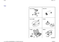


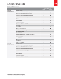
© Copyright 2026