
Enterra 4351 Implant Manual
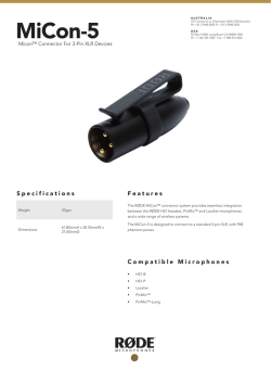
4351_Enterra_fcv.fm 2/16/12 3:10 pm
Medtronic Confidential
package_R00a
4 x 8 inches (101 mm x 203 mm)
Enterra® Therapy
4351
Unipolar Intramuscular Lead for the Gastric
Electrical Stimulation System
Humanitarian device: Authorized by Federal
law for use in the treatment of chronic intractable
(drug-refractory) nausea and vomiting secondary
to gastroparesis of diabetic or idiopathic etiology.
The effectiveness of this device for this use has
not been demonstrated.
Technical manual
Rx only
MA01352A004
Rev X
4351_Enterra_fcv.fm 2/16/12 3:10 pm
Medtronic Confidential
package_R00a
4 x 8 inches (101 mm x 203 mm)
Medtronic® and Enterra® are trademarks of Medtronic, Inc., registered in
the U.S. and other countries.
MA01352A004
Rev X
4351_EnterraTOC.fm 2/16/12 3:10 pm
4 x 8 inches (101 mm x 203 mm)
Medtronic Confidential
package_R01
Table of contents
Device description 5
Package contents 5
Indications 6
Contraindications 6
Physician training 6
Patient counseling 6
Warnings 7
Theft detectors and security screening devices 8
Precautions 10
Inspecting the package 10
Handling the lead 10
General precautions 10
Lead repositioning 10
Patient considerations 10
Adverse events summary 11
Clinical studies 11
WAVESS study 11
WAVESS Compassionate Use study (WCU) 13
Compassionate Use Electrical Stimulation Study (CUESS)
WAVESS results 16
Adverse events 18
Resterilization 21
Directions for use 22
Implant the lead 22
Anchor the lead 23
Create pocket for neurostimulator 24
Connecting leads to neurostimulator 25
Using lead end cap 27
Verify impedance and close pocket 28
Program Enterra Therapy System 29
Program basic neurostimulator parameters 29
Program output current 30
Postoperative programming schedule 31
Detailed device description 32
Specifications 32
Special notice 33
Warranty 34
Enterra 4351 Implant Manual
MA01352A004
Rev X
14
2012-06
3
4351_EnterraTOC.fm 2/16/12 3:10 pm
4 x 8 inches (101 mm x 203 mm)
4
2012-06
MA01352A004
Enterra 4351 Implant Manual
Rev X
Medtronic Confidential
package_R01
Medtronic Confidential
Pkg_R00a
4351_Enterra_CH.fm 2/16/12 3:10 pm
4 x 8 inches (101 mm x 203 mm)
Device description
The Enterra Therapy System for gastric electrical stimulation is comprised
of a neurostimulator, leads, programmer, and programmer software.
The Medtronic Model 4351 Lead (see Figure 1) is a unipolar, intramuscular
lead with a fixed 10-mm electrode. The lead comes with a 3.2 mm low profile
Medtronic standard lead connector in a unipolar configuration. Only the pin
connector is mechanically and electrically connected in the unipolar
configuration.
Insertion “ski” needle
Trumpet
Anchor
Electrode
Blue Polypropylene
Monofilament (10 cm)
Setscrew grommets
Connector pin
3.2 mm Low-Profile Connector
Connector
block
Enterra Therapy Neurostimulator
Suture
holes
Figure 1. Lead Model 4351 with neurostimulator.
The lead has a polyurethane insulation and a flexible electrode coil made of
platinum and iridium.
The platinum-iridium electrode tip is mechanically and electrically
connected to the electrode coil. The lead has an attached, non-absorbable
blue polypropylene monofilament and a ski needle for lead insertion.
The Model 4351 Lead is intended to be used with the following Medtronic
products:
• Model 7425G Neurostimulator
• Model 3116 Neurostimulator
• Model 7432 Physician Programmer
• MemoryMod Model 7457 or 7459 Programmer Software
• Model 8840 N’Vision Clinician Programmer
• Model 8870 Software Application Card
The lead is designed for intramuscular implantation to deliver electrical
current to the stomach muscle.
Package contents
The Medtronic Model 4351 Lead package contains the following:
• One Model 4351 Lead (with pre-attached anchor and suture with
insertion needle)
• Four fixation disks
• Tunneling rod
• Two lead end caps
• Product literature
Note: The contents of the inner package are sterile (ethylene-oxide
sterilized).
Enterra 4351 Implant Manual
MA01352A004
Rev X
2012-06
5
4351_Enterra_CH.fm 2/16/12 3:10 pm
4 x 8 inches (101 mm x 203 mm)
Medtronic Confidential
Pkg_R00a
Indications
The Enterra gastric lead is indicated for the treatment of patients with
chronic, intractable (drug-refractory) nausea and vomiting secondary to
gastroparesis of diabetic or idiopathic etiology.
Contraindications
The Enterra Therapy System is contraindicated in patients whom the
physician determines are not candidates for surgical procedures and/or
anesthesia due to physical or mental health conditions.
Do not use shortwave diathermy, microwave diathermy or therapeutic
ultrasound diathermy (all now referred to as diathermy) on patients
implanted with a neurostimulation system. Energy from diathermy can be
transferred through the implanted system and can cause tissue damage at
the location of the implanted electrodes, resulting in severe injury or death.
Diathermy is further prohibited because it can also damage the
neurostimulation system components resulting in loss of therapy, requiring
additional surgery for system explantation and replacement. Injury or
damage can occur during diathermy treatment whether the neurostimulation
system is turned “ON” or “OFF.” Advise your patients to inform all their health
care providers that they should not be exposed to diathermy treatment.
Physician training
Prescribing physicians are encouraged to contact Medtronic for available
educational opportunities regarding the surgical and/or implantation
techniques, operational characteristics and functions of the Enterra Therapy
System prior to prescribing the device for the first time. All programming
should be by or under the supervision of a physician or other experienced
medical personnel familiar with the use of the programming software.
Patient counseling
The patient and family should be advised of the known risks of the surgical
procedure and the therapy (as discussed in the other sections of this
manual), as well as the potential benefits. The patient should be advised to
read The Enterra Therapy Gastric Electrical Stimulation System Patient
Manual, which is included in the Model 7425G and 3116 Neurostimulator
packages.
6
2012-06
MA01352A004
Enterra 4351 Implant Manual
Rev X
4351_Enterra_CH.fm 2/16/12 3:10 pm
4 x 8 inches (101 mm x 203 mm)
Medtronic Confidential
Pkg_R00a
Warnings
Age limitations – The safety and effectiveness of this therapy has not been
established for patients under age 18 or over age 70.
Allergic reaction – There is a possibility of an allergic or immune system
response to the implanted materials.
Anticoagulation therapy – Patients on anticoagulation therapies may be
at a greater risk for postoperative complications, such as hematomas.
Interaction with other implantable devices – When another implantable
device (eg, pacemakers, defibrillators, or cochlear implants) is required, the
physicians involved in both therapies should discuss the possible
interaction between the devices. Electrical impulses from the
neurostimulation system may affect the sensing operation and cause
inappropriate device response of other implanted devices. Careful
programming of each system may optimize the benefit from each device.
Follow these suggested guidelines:
• The neurostimulator should be placed on the opposite side of the
body from the other implanted device.
• The neurostimulator should be reprogrammed to bipolar stimulation.
• Each system should be checked to ensure that it is working as
intended.
Component compatibility – Use only Medtronic components that are
compatible with this system. The use of non-Medtronic components with this
stimulation system can result in damage to Medtronic components, loss of
therapy, or patient injury.
Electrocautery – Electrocautery can damage the lead or neurostimulator.
It can also cause temporary suppression of neurostimulator output and it
can reprogram the neurostimulator to Power ON Reset parameters (output
OFF, amplitude = 0V). This requires the clinician to reprogram the
neurostimulator. Electrocautery may also cause induced currents in the lead
portion of the neurostimulation system that could be hazardous or cause
further injury.
Follow these precautions when using electrocautery:
• Turn OFF the neurostimulator before performing electrocautery.
• Do not contact the lead with the electrocautery device.
• Only bipolar cautery is recommended.
• If unipolar cautery is necessary:
• Do not use high voltage modes.
• Keep the power setting as low as possible.
• Keep the current path (ground plate) as far away from the
neurostimulator and lead as possible.
• Confirm the neurostimulator function after electrocauterization.
Radiation therapy – Do not direct high radiation sources, such as cobalt 60
or gamma radiation, at the neurostimulation system. If radiation therapy is
required in the vicinity of the neurostimulation system, place lead shielding
over the device to prevent radiation damage.
High-Output Ultrasonics / Lithotripsy – Use of high-output ultrasonic
devices, such as electrohydraulic lithotriptor, is not recommended for
patients with an implanted neurostimulation system. If lithotripsy must be
used, do not focus the beam within 6 inches (15 cm) of the neurostimulator.
Defibrillation / Cardioversion – When a patient is in ventricular or atrial
fibrillation, the first consideration should be patient survival. External
defibrillation or cardioversion can cause permanent damage to a
neurostimulation system. It is recommended not to use defibrillation or
cardioversion paddles near the neurostimulator. When external defibrillation
or cardioversion is necessary, minimize the current flowing through the
neurostimulator and lead system as follows:
• Position paddles as far from the neurostimulator as possible.
• Position paddles perpendicular to the neurostimulation system.
• Use the lowest clinically appropriate energy output (watt seconds).
Enterra 4351 Implant Manual
MA01352A004
Rev X
2012-06
7
4351_Enterra_CH.fm 2/16/12 3:10 pm
4 x 8 inches (101 mm x 203 mm)
Medtronic Confidential
Pkg_R00a
Defibrillation or cardioversion may also cause induced currents in the lead
portion of the neurostimulation system that could be hazardous or cause
further injury.
Confirm the neurostimulation system function after external defibrillation.
Magnetic Resonance Imaging (MRI) – Patients with an implanted device
should not be exposed to the electromagnetic fields produced by magnetic
resonance imaging (MRI). Use of MRI may potentially result in system
failure, dislodgement, heating, or induced voltages in the neurostimulator
and/or lead. An induced voltage through the neurostimulator or lead may
cause uncomfortable, “jolting,” or “shocking” levels of stimulation. Clinicians
should carefully weigh the decision to use MRI in patients with an implanted
neurostimulation system, and note the following:
• Magnetic and radio-frequency (RF) fields produced by MRI may
change the neurostimulator settings and injure the patient.
• Patients treated with MRI should be closely monitored and
programmed parameters verified upon cessation of MRI.
Pregnancy – Safety for use during pregnancy or delivery has not been
established.
Infection – It is recommended that the neurostimulator implant site be
irrigated with antibiotic solution during surgery and that IV antibiotics be
administered perioperatively. When possible, identify and treat any
infections remote to the implant site prior to surgery. Infections at the
implant site almost always require the surgical removal of the implanted
system.
Bowel obstruction/perforation – The lead can become entangled with or
erode into the bowel, which can result in bowel obstruction and perforation.
Either may lead to life-threatening intra-abdominal infections and may
require laparotomy, bowel resection, and system revision. Avoid excess
lead slack in the abdominal cavity. Post implant, consider lead
entanglement or erosion as a possible etiology in patients with bowel
obstruction symptoms.
Theft detectors and security screening devices
Patients should be advised to use care when approaching theft detector and
security screening devices (such as those found in airports, libraries, and
some department stores). When approaching these devices, patients
should do the following:
1. If possible, request to bypass these devices. The patient should
show the security personnel their patient identification card for the
neurostimulator and request a manual search. Security personnel
may use a handheld security wand but the patient should ask the
security personnel not to hold the security wand near the
neurostimulator any longer than is absolutely necessary. The patient
may wish to ask for another form of personal search.
2. If patients must pass through the theft detector or security screening
device, they should approach the center of the device and walk
through normally (Figure 2).
a. If two security gates are present, they should walk through the
middle, keeping as far away as possible from each gate.
b. If one gate is present, they should walk as far away as possible
from it.
Note: Some theft detectors may not be visible.
3. Proceed through the security device. Do not linger near or lean on
the screening device.
8
2012-06
MA01352A004
Enterra 4351 Implant Manual
Rev X
4351_Enterra_CH.fm 2/16/12 3:10 pm
4 x 8 inches (101 mm x 203 mm)
Double
Security
Gate
Medtronic Confidential
Pkg_R00a
Single Security Gate
(Stay as far away as
possible from gate)
Figure 2. Approaching security gates.
Enterra 4351 Implant Manual
MA01352A004
Rev X
2012-06
9
4351_Enterra_CH.fm 2/16/12 3:10 pm
4 x 8 inches (101 mm x 203 mm)
Medtronic Confidential
Pkg_R00a
Precautions
Inspecting the package
Inspect the lead’s sterile package prior to opening. If the seal or package is
damaged, contact your local Medtronic representative.
Handling the lead
• Do not implant a neurostimulator if it has been dropped onto a hard
surface from a height of 12 in (30 cm) or more.
• Do not immerse the lead in mineral oil, silicone oil, or any other
equivalent.
• Lead insulators attract small particles such as lint and dust;
therefore, to minimize contamination protect the lead from materials
shedding these substances. Handle the lead with sterile surgical
gloves that have been rinsed in sterile water or equivalent.
• Do not implant a lead that was dropped; the lead may no longer be
sterile.
• Any severe bending, kinking, stretching, or handling with surgical
instruments may cause permanent damage to the electrode coil,
conductor coil, connector, or the lead body. If the lead is damaged,
do not implant. Return the lead to your Medtronic representative.
–
Do not tie a suture directly to the lead body, because the suture
could cut through the lead insulation. Use the anchor on the
lead and the fixation disks, which are supplied with the lead kit.
Do not overtighten sutures to avoid damage to the anchor or
fixation disk.
–
Do not use a hemostat on the lead body.
–
If handling the lead with forceps, use only rubber-tipped
bayonet forceps.
• Wipe off any body fluids on the lead contacts or connector before
connecting the lead to the neurostimulator. Contamination of the
connections can affect gastric stimulation.
• Take care to avoid accidental bending of the electrode coil and the
conductor coil; the angulation required to restore the electrode’s
original shape may weaken or fracture the electrode.
General precautions
• The physician should be aware that gastric stimulation systems may
unexpectedly cease to function. A system may fail at any time due
to random failures of the system components or the battery (prior to
depletion). These events, which can include electrical shorts or
opens and insulation breaches, cannot be predicted.
Lead repositioning
• Repositioning the lead is not recommended after implantation. If
necessary, replace the lead. Removing the lead after
long-term implant may be difficult due to fibrotic tissue development.
If you cannot remove the lead safely, it is recommended that the
lead be left in position . Place a lead end cap over the connector pin
and secure the end cap with a suture (see “Using lead end cap”).
Patient considerations
• Select patients carefully to assure that their symptoms are of
physiological origin. Patients must be appropriate candidates for
surgery.
• It is recommended that patients undergo detoxification from
narcotics prior to implant.
• So that the benefit from the gastric stimulation system may be
optimized, long-term, postsurgical management of the patient is
strongly encouraged.
10
2012-06
MA01352A004
Enterra 4351 Implant Manual
Rev X
Medtronic Confidential
Pkg_R00a
4351_Enterra_CH.fm 2/16/12 3:10 pm
4 x 8 inches (101 mm x 203 mm)
Adverse events summary
In addition to those risks associated with surgery, implantation or use of a
neurostimulation system includes, but is not limited to, the following risks:
• Lead impedance out of range
• Undesirable change in stimulation, possibly related to cellular
charges around the electrodes, shifts in electrode position, loose
electrical connections, or lead fractures
• Loss of therapeutic effect
• Lead or neurostimulator erosion or migration, which may necessitate
surgical revision
• Bowel obstruction, perforation, ileus, or necrosis
• Infections, including device/implant site infections, intra-abdominal
infections, abscess, peritonitis, sepsis, urinary tract infections
• Stomach wall perforation
• Upper and lower gastro-intestinal (GI) symptoms
• Hemorrhage, hematoma, and possible GI complications resulting
from the surgical procedure to implant the neurostimulator and leads
• Persistent pain at the neurostimulator site
• Extra-abdominal pain, bone- and joint-related pain
• Seroma at the neurostimulator site
• Allergenic or immune system response to implanted materials
• Stress incontinence
• Fever
• Feeding tube complications
• Dehydration
• Dysphagia
• Acute diabetic complications
• Cardiovascular renal related events
The adverse events observed during the clinical evaluation of the Enterra
Therapy System are summarized in Table 9. These events were related to
the device or implant surgery.
Clinical studies
Patients with drug-refractory gastroparesis of diabetic or idiopathic
etiologies were evaluated in the following clinical studies: the World Wide
Anti-Vomiting Electrical Stimulation Study (WAVESS), the WAVESS
Compassionate Use Study (WCU), and the Compassionate Use Electrical
Stimulation Study (CUESS).
WAVESS study
The WAVESS study was a double-blind, randomized cross-over study that
enrolled a total of 33 subjects. The study was designed to collect both safety
and effectiveness information.
WAVESS study objective
The primary endpoint of the study was a reduction in vomiting frequency, as
measured by patient diaries. The treatment was considered successful if a
reduction in vomiting frequency by at least 80% was observed during the
cross-over period of the study with the ON-mode stimulation, when
compared to the OFF-mode stimulation.
The secondary endpoints in the study were quality of life (measured with the
Medical Outcomes Study Short-Form 36 Health Survey), body mass index,
hypoglycemic attacks (diabetic group only), subjective symptoms
documented by a clinical status interview, glycosylated hemoglobin, and
gastric emptying documented with a gastric emptying test.
Enterra 4351 Implant Manual 2012-06
MA01352A004
Rev X
11
Medtronic Confidential
Pkg_R00a
4351_Enterra_CH.fm 2/16/12 3:10 pm
4 x 8 inches (101 mm x 203 mm)
WAVESS entry criteria
The inclusion criteria for the study included:
• Symptomatic gastroparesis ≥ 1 year, as documented by an initial
Gastric Emptying Test (GET)
• Refractory or intolerant to at least two antiemetic and two prokinetic
drug classes
• On stable medical therapy, and, if applicable, stable nutritional
support during the month prior to enrollment
• Frequency of vomiting > 7 vomiting episodes per week, as
documented with a baseline patient diary
• Delayed gastric emptying, defined by greater than 60% retention at
two hours and > 10% retention at four hours, as measured by
standardized gastric emptying testing
The exclusion criteria included:
• Organ transplant
• Organic obstruction
• Pseudo-obstruction
• Prior gastric surgery
• Scleroderma
• Amyloidosis
• History of seizures
• Peritoneal or unstable dialysis
• Chemical dependency
• Pregnancy
• Primary eating or swallowing disorders
• Psychogenic vomiting
• Implanted electronic medical devices
• Age < 18 or > 70 years
WAVESS study enrollment
Enrollment and follow-up in the WAVESS study was as follows:
Table 1. Enrollment in WAVESS Study
Number of
Subjects
at
enrollment
implanted>
30 days
(N)
33
33
implanted> implanted>
60 days
6 Months
33
27
implanted>
12 Months
24
WAVESS study demographics
A total of 33 subjects were enrolled in the WAVESS study. The demographic
information on these subjects is presented in the table below:
Table 2. Patient Demographics
Diabetic
(N=17)
Idiopathic
(N=16)
Total
(N =33)
Gender (M/F)
9/8 F
0/16 F
9/24 F
Age, mean
38.1
41.1
39.6
BMI, mean
24.7
22.9
23.7
79.7/80.0
53.2/51.0
73.1/76.5
34.3/28.0
76.5/78.0
44.0/34.0
Gastric retention (mean/median)%
@ 2 hours
@ 4 hours
12
2012-06
MA01352A004
Enterra 4351 Implant Manual
Rev X
4351_Enterra_CH.fm 2/16/12 3:10 pm
4 x 8 inches (101 mm x 203 mm)
Medtronic Confidential
Pkg_R00a
WAVESS study design
Subjects satisfying entry criteria received gastric stimulation systems that
included an implanted neurostimulator connected to two unipolar leads that
were implanted in the muscle wall of the stomach on the greater curvature
at the limit of the corpus-antrum. All subjects received a Model 7425
implantable neurostimulator and a pair of Model 43001 leads. The
stimulation parameters used in the study were: Intensity: 5 mA, Pulse Width:
330 µsec, Frequency: 14 Hz. The neurostimulator was set to deliver a pair
of pulses at these parameters every five seconds continuously 24 hours per
day.
The study was conducted in two phases:
1. Phase I was a double blind crossover study with evaluations prior to
implant and at 30 days and 60 days post-implant. Subjects were
randomly assigned to stimulation ON and OFF for the first month
after implant and were crossed to OFF and ON for the second
month. Subjects were blinded as to which stimulation sequence they
received.
2. Phase II was an unblinded open label study with follow-up at six and
twelve months. After the crossover period was complete, the
subjects were asked which month of the crossover stimulation they
preferred. After the selection was made, the study blind was broken.
The subjects then received stimulation (ON or OFF) consistent with
their preference.
The primary and the secondary endpoints, except gastric emptying, were
measured at baseline, 30 days, 60 days, six months, and twelve months
postrandomization. Gastric emptying was measured at baseline, and six
and twelve months postrandomization.
Primary endpoint evaluations included weekly vomiting frequency and
patient preference within Phase I of the study. Secondary endpoint
evaluations included gastric retention, hypoglycemic attacks, upper GI
symptoms, and quality of life using the Medical Outcomes Study Short-Form
36 Health Survey.
WAVESS Compassionate Use study (WCU)
The WAVESS Compassionate Use study (WCU) was an open label, nonrandomized study that included a total of 18 subjects. The WCU study was
designed to provide safety (adverse events) information on gastric
stimulation.
WCU study objective
The purpose of the WCU study was to provide treatment for patients and to
evaluate adverse events of patients with drug-refractory gastroparesis who
did not meet the entry criteria of the WAVESS study.
1
The Model 7425G Neurostimulator is identical to the Model 7425
Neurostimulator used in the clinical study. The Model 4351 Lead is similar
to the Model 4300 Lead used in the clinical study. The Model 4351 Lead
has a fixed electrode length of 10 mm, whereas the Model 4300 Lead had
an adjustable electrode length.
Enterra 4351 Implant Manual
MA01352A004
Rev X
2012-06
13
Medtronic Confidential
Pkg_R00a
4351_Enterra_CH.fm 2/16/12 3:10 pm
4 x 8 inches (101 mm x 203 mm)
WCU entry criteria
Candidates eligible for the WCU study consisted of those subjects who did
not meet the complete entry criteria for the WAVESS study, but who had
documentation of drug-refractory gastroparesis.
The study entry criteria were:
• Did not meet the entry criteria of the WAVESS Study
• Were likely to die within the next few weeks if they did not receive
this therapy
• Signed an informed consent form relevant to this study
This WAVESS Compassionate Use Study required:
• Documentation of life-threatening situation by an independent
physician
• IRB (or IRB chairperson) approval on a case-by-case basis
• An additional informed consent form relevant to the applicable
patient’s condition was approved by the clinical investigator and the
IRB or IRB chairperson (this varied depending on the reason(s) why
the patient did not qualify for the WAVESS study)
WCU study demographics
A total of 24 subjects were enrolled in the WCU study. The demographic
information on these subjects is presented in the table below:
Table 3. Patient Demographics
Diabetic
Idiopathic
Postsurgical
6
17
1
1M/5F
17 F
1F
Age, mean
36.4
35.7
69.0
BMI, mean
20.5
23.1
18.4
N
Gender
Baseline:
Vomiting Severity (mean)
3.5
3.6
4.0
Nausea Severity (mean)
3.3
3.6
4.0
GET 2 Hr (median)
74.0
67.0
18.0
GET 4 Hr (median)
34.0
22.0
2.0
WCU study design
Subjects satisfying entry criteria received gastric stimulation systems which
included an implanted neurostimulator connected to two unipolar leads
which were implanted in the muscle wall of the stomach on the greater
curvature at the limit of the corpus-antrum. All subjects received a Model
7425 implantable neurostimulator and a pair of Model 4300 leads. The
stimulation parameters used in the study were: Intensity: 5 mA, Pulse Width:
330 µsec, Frequency: 14 Hz. The neurostimulator was set to deliver a pair
of pulses at these parameters every five seconds continuously 24 hours per
day. The stimulation parameters could be adjusted at any time by the
physician to optimize treatment therapy.
In contrast to the WAVESS study design, the WCU study was an unblinded,
open label study. Upon implantation of the device within each patient, the
stimulation therapy was immediately initiated without a randomized ON/
OFF cross-over period.
Compassionate Use Electrical Stimulation Study (CUESS)
The Compassionate Use Electrical Stimulation Study was an open label,
non-randomized study that included a total of 51 subjects. This study was
designed to provide gastric stimulation safety information.
14
2012-06
MA01352A004
Enterra 4351 Implant Manual
Rev X
Medtronic Confidential
Pkg_R00a
4351_Enterra_CH.fm 2/16/12 3:10 pm
4 x 8 inches (101 mm x 203 mm)
CUESS study objective
The purpose of the Compassionate Use Electrical Stimulation Study was to
treat patients with drug-refractory gastroparesis who had no other medical
treatment alternative.
CUESS entry criteria
The inclusion criteria for the study were:
• Symptomatic gastroparesis ≥ 1 year, as documented by an initial
gastric emptying test (GET)
• Refractory or intolerant to at least two antiemetic and prokinetic drug
classes
• On stable medical therapy during the month prior to enrollment
• Frequency of vomiting > 7 vomiting or nausea episodes per week,
as documented with a baseline patient diary
• Delayed gastric emptying, defined by greater than 50% retention at
two hours and > 6% retention at four hours, as measured by
standardized gastric emptying testing
The exclusion criteria were:
• Organ transplant
• Organic obstruction
• Pseudo-obstruction
• Scleroderma
• Amyloidosis
• Peritoneal or unstable dialysis
• Chemical dependency
• Pregnancy
• Primary eating or swallowing disorders
• Psychogenic vomiting
• Implanted electronic medical devices
• Age < 18 or > 70 years
CUESS study demographics
A total of 50 subjects were enrolled, screened, and qualified in the
Compassionate Use Electrical Stimulation Study. The demographic
information on these subjects is presented in the table below:
Table 4. Patient Demographics
Diabetic
N
Idiopathic
Postsurgical*
22
19
9
10 / 12 F
1 / 18 F
1/8F
Age, mean
39.8
44.5
48.8
BMI, mean
23.5
22.4
23.5
@ 2 Hours
79.5
51.0
73.5
@ 4 Hours
39.5
21.0
33.5
Gender (M/F)
Gastric retention (median)%
*Enterra Therapy System is not currently indicated for postsurgical gastroparesis
CUESS study design
Subjects satisfying entry criteria received gastric stimulation systems which
included an implanted neurostimulator connected to two unipolar leads
which were implanted in the muscle wall of the stomach on the greater
curvature at the limit of the corpus-antrum. All subjects received a Model
7425 implantable neurostimulator and a pair of Model 4300 leads. The
Enterra 4351 Implant Manual
MA01352A004
Rev X
2012-06
15
Medtronic Confidential
Pkg_R00a
4351_Enterra_CH.fm 2/16/12 3:10 pm
4 x 8 inches (101 mm x 203 mm)
stimulation parameters used in the study were: Intensity: 5 mA, Pulse Width:
330 µsec, Frequency: 14 Hz. The neurostimulator was set to deliver a pair
of pulses at these parameters every five seconds continuously 24 hours per
day.
The stimulation parameters could be adjusted at any time by the physician
to optimize treatment therapy. In contrast to the WAVESS study design,
Compassionate Use Electrical Stimulation Study was an unblinded open
label study. Upon implantation of the device within each patient, the
stimulation therapy was immediately initiated without a randomized ON/
OFF crossover period.
WAVESS results
The effectiveness results described below were obtained from the WAVESS
study.
Primary endpoint evaluations:
Weekly vomiting frequency was determined for each patient diary. These
data were further analyzed by Wilcoxon signed-rank test. For the combined
patient group, median weekly vomiting frequency declined 49.6% in the ON
period vs. the OFF period (p<0.05) (see Table 5). Before breaking the blind
at the end of Phase I, 21 patients (10 diabetic, 11 idiopathic) preferred
stimulation ON, while 7 (4 diabetic and 3 idiopathic) preferred stimulation
OFF, and 5 (3 diabetic and 2 idiopathic) had no preference. These results
were analyzed by the Mainland-Gart test and were statistically significant for
the idiopathic and the combined group (p<0.05). At the end of Phase I,
subjects were unblinded and given the option of having the device
programmed ON or OFF. At the six month follow-up, all subjects had the
device programmed ON. Each patient had the option of having stimulation
turned OFF or ON at any time during the Phase II period.
Table 5. Vomiting Frequency, WAVESS Phase I, All Subjects (N=33)
Vomiting
Episodes per
Week
Baseline
ON
OFF
Difference
(OFF-ON)
%
Difference
Mean (N±SD)
37.3 ± 45.1
15.9 ± 25.0
23.6 ± 35.6
7.7
32.6
17.3
6.8
13.5
6.7
49.6
Median (N)
Although 33 patients completed the two-month crossover period of the study
(through Phase I), data at six months is provided for only 27 patients. Of
these 27 patients, some patients had the device turned to the ON mode
immediately at the end of the Phase I period, while others had the device
turned ON later. By the end of the fourth month postrandomization, all 27
patients had the device turned ON. As a result, the vomiting frequency at six
months documented in Table 6 was obtained from patients who received
continuous stimulation for at least two months.
Vomiting frequency results at 6 and 12 months post-implantation are shown
in Tables 6–8. Table 6 includes data for all subjects, while Tables 7 and 8
include data for the idiopathic and diabetic gastroparesis groups,
respectively. The vomiting frequency at 6 and 12 months was significant
compared to baseline.
Table 6. Vomiting Frequency, WAVESS Phase II, All Subjects
All
Patients
Combined
N
Mean Number
of Episodes,
± SD
Median
Number of
Episodes
16
2012-06
MA01352A004
Baseline
6
Months
%
Difference
Baseline
12
Months
%
Difference
33
27
—
33
24
—
37.3±45.1 13.7±30.2
17.3
2.6
-63
-85
Enterra 4351 Implant Manual
Rev X
37.3±45.1 8.5±16.3
17.3
4.8
-77
-72
Medtronic Confidential
Pkg_R00a
4351_Enterra_CH.fm 2/16/12 3:10 pm
4 x 8 inches (101 mm x 203 mm)
Table 6. Vomiting Frequency, WAVESS Phase II, All Subjects (continued)
All
Patients
Combined
Baseline
6
Months
%
Difference
Baseline
12
Months
%
Difference
Patients with
> 50%
vomiting
reduction vs
baseline,
N (%)
—
16/27 (59)
—
—
18/24 (75)
—
Patients with
> 80%
vomiting
reduction vs
baseline,
N (%)
—
13/27 (48)
—
—
13/24 (54)
—
Table 7. Vomiting Frequency, WAVESS Phase II, Idiopathic Gastroparesis Subjects
All
Patients
Combined
N
Mean Number
of Episodes,
+/–SD
Median
Number of
Episodes
Baseline
6
Months
%
Difference
Baseline
12
Months
%
Difference
16
14
—
16
13
—
44.3±55.5 12.1±25.1
-73
43.3±55.5 11.8±21.2
-73
26.8
3.0
-88
26.8
4.5
-83
Patients with
> 50%
vomiting
reduction vs
baseline,
N (%)
—
9/14 (64)
—
—
10/13 (77)
—
Patients with
> 80%
vomiting
reduction vs
baseline,
N (%)
—
8/14 (57)
—
—
7/13 (54)
—
Table 8. Vomiting Frequency, WAVESS Phase II, Diabetic Gastroparesis Subjects
All
Patients
Combined
N
Mean Number
of Episodes
Median
Number of
Episodes,
+/–SD
Baseline
6
Months
%
Difference
Baseline
12
Months
%
Difference
16
13
—
16
11
—
30.3 ± 31.9 15.7 ± 36.4
13.4
2.6
-48
-80
30.3 ± 31.9 4.2 ± 3.9
13.4
Enterra 4351 Implant Manual
MA01352A004
Rev X
4.9
-87
-63
2012-06
17
Medtronic Confidential
Pkg_R00a
4351_Enterra_CH.fm 2/16/12 3:10 pm
4 x 8 inches (101 mm x 203 mm)
Table 8. Vomiting Frequency, WAVESS Phase II, Diabetic Gastroparesis Subjects
All
Patients
Combined
Baseline
6
Months
%
Difference
Baseline
12
Months
%
Difference
Patients with
> 50%
vomiting
reduction vs
baseline,
N (%)
—
7/12 (58)
—
—
8/11 (73)
—
Patients with
> 80%
vomiting
reduction vs
baseline,
N (%)
—
5/12 (42)
—
—
6/11 (55)
—
WAVESS Secondary endpoint evaluations
The results of secondary endpoint evaluations indicate that many patients
experienced improvements in quality of life (73%) and ability to tolerate solid
meals (73%). Additionally, there was a trend in improvement for gastric
retention, subjective symptoms, and hypoglycemic attacks.
Adverse events
The adverse events information (Table 9) was obtained from the WAVESS
study (N=27), the WAVESS Compassionate Use study (N=24), and the
CUESS study (N=49). Adverse events were reported at each follow-up visit
or at interim periods as appropriate in both studies. Table 9 summarizes
those system related adverse events reported through May 22, 2003.
18
2012-06
MA01352A004
Enterra 4351 Implant Manual
Rev X
MA01352A004
Rev X
Enterra 4351 Implant Manual
5
Pain at neurostimulator site
2
5
Irritation/inflammation over neurostimulator site
Seroma at pocket
3
Lead impedance out of range
1
1
Lead revision
2
1
4
4
3
1
4
1
1
1
1
1
7
Patients
7
4
15
15
11
4
15
4
4
4
4
4
26
% of
Patients
1
0
0
5
5
0
1
2
0
0
0
0
4
Events
1
0
0
5
5
0
1
1
0
0
0
0
4
Patients
4
0
0
21
21
0
4
4
0
0
0
0
17
% of
Patients
WAVESS
Compassionate Use N=24
0
2
2
0
3
0
0
1
0
1
0
0
5
Events
0
2
2
0
2
0
0
1
0
1
0
0
5
Patients
CUESS*
N=49
0
4
4
0
4
0
0
2
0
2
0
0
10
% of
Patients
4 x 8 inches (101 mm x 203 mm)
Concomitant stimulation of abdominal rectus muscle
4
Lead penetration
1
Hematoma at pocket
1
1
Extrusion of neurostimulator through incision
Neurostimulator migration
1
Device erosion
1
10
Device infections
Infection in wound incision/abdominal wall
Events
Event description
WAVESS
N=27
Table 9. Summary Study of System Related Adverse Events*
4351_Enterra_CH.fm 2/16/12 3:10 pm
Medtronic Confidential
Pkg_R00a
2012-06
19
20
2012-06
MA01352A004
Rev X
0
0
0
0
0
0
0
0
Extra-abdominal pain
Epigastric pain
Surgical removal of IV access
Electrical shocks with discomfort
Enterra 4351 Implant Manual
Patient “Can’t eat as well as before therapy.”
Left side nerve rib pain
Uncomfortable neurostimulator location
Fluid collection at neurostimulator site with erythema over RLQ
0
0
0
0
0
0
0
0
0
0
0
0
Patients
0
0
0
0
0
0
0
0
0
0
0
0
% of
Patients
0
0
0
0
0
0
0
0
0
1
1
2
Events
0
0
0
0
0
0
0
0
0
1
1
2
Patients
0
0
0
0
0
0
0
0
0
4
4
8
% of
Patients
WAVESS
Compassionate Use N=24
1
2
1
1
1
1
1
4
1
0
1
0
Events
1
2
1
1
1
1
1
4
1
0
1
0
Patients
CUESS*
N=49
2
4
2
2
2
2
2
8
2
0
2
0
% of
Patients
4 x 8 inches (101 mm x 203 mm)
*Refer to “Table 9 Notes” on page 21
0
0
Failure of wound healing
0
Inability to program device/programming difficulty
Tingling sensation
0
Events
Surgical removal of system due to discomfort
Event description
WAVESS
N=27
Table 9. Summary Study of System Related Adverse Events*
4351_Enterra_CH.fm 2/16/12 3:10 pm
Medtronic Confidential
Pkg_R00a
4351_Enterra_CH.fm 2/16/12 3:10 pm
4 x 8 inches (101 mm x 203 mm)
Medtronic Confidential
Pkg_R00a
Table 9 Notes
The decline in the rate of device-related adverse events from the WAVESS
to the CUESS protocols may be related to several factors:
• During patient enrollment in the WAVESS study, the protocol
was modified to require intraoperative endoscopy to ensure
that neither stimulating lead perforated the stomach.
• During the WAVESS study, the physicians were encouraged to
administer perioperative antibiotics to minimize the potential for
infections at the implant site.
• At one center, the majority of the 39 total cases implanted in the
three protocols were done by one surgeon, and 4 infections
(10.3%) were reported.
• At another center, 11 systems were implanted in the three
protocols and 5 infections (45.5%) were reported. All implant
procedures in the WAVESS study and WAVESS
Compassionate Use study were done by laparotomy, whereas
5 (10.2%) of the 49 in CUESS were done by laparoscopy.
CUESS (N=49): Two diabetic patients who were implanted but did not
qualify for the CUESS protocol were excluded from this summary table.
Resterilization
The Model 4351 lead and its accessories should not be resterilized.
The Model 4351 lead and its accessories have been sterilized using
ethylene-oxide. Inspect the sterile package for seal integrity and damage to
the package before opening and using the contents. If you are unsure of the
components’ sterility for any reason (except when the “Use by” date has
expired), they should be returned to Medtronic. Please contact your
Medtronic representative for instructions.
Note: If contamination is suspected because of a defective sterile package
seal, lead and accessories can be returned to Medtronic for replacement.
Replacements are otherwise subject to terms of the Medtronic Limited
Warranty (U.S. Customers).
Enterra 4351 Implant Manual
MA01352A004
Rev X
2012-06
21
4351_Enterra_CH.fm 2/16/12 3:10 pm
4 x 8 inches (101 mm x 203 mm)
Medtronic Confidential
Pkg_R00a
Directions for use
Implant the lead
Implant two leads into the circular muscle layer along the greater curvature
of the stomach (Figure 3), 10 cm proximal to the pylorus. Place the leads 1
cm apart for optimal stimulation (eg, 9.5 cm and 10.5 cm). Electrodes can
be placed in a variety of angles, but they should be placed parallel to each
other. The electrode placement angle should ensure that neither end of the
lead has sharp bends or kinks when it is connected to the neurostimulator.
Medtronic recognizes that a variety of approaches may be used to
accomplish this; therefore, the following implant procedure is presented as
one possible approach for the physician to consider.
Figure 3. Place the leads 10 cm proximal to the pylorus and 1.0 cm apart.
1.
Prepare the patient per normal procedures for abdominal surgery.
Warning: It is recommended that the neurostimulator implant site
be irrigated with antibiotic solution during surgery, and that IV
antibiotics be administered perioperatively. When possible, identify
and treat any infections remote to the implant site prior to surgery.
Infections at the implant site almost always require the surgical
removal of the implanted system.
2.
3.
4.
22
Note: To help facilitate implantation, you may prepare the system by
tying sutures onto the trumpet anchor, fixation disk, and
neurostimulator connector block. Do not use absorbable suture
material.
Using either a laparotomy or laproscopic surgical procedure, expose
and visualize the antrum of the stomach.
Note: If using laparoscopic approach, ensure that the port is
sufficient in diameter to accommodate the lead.
Measure 10 cm proximal from the pylorus.
Use the needle to insert the lead into the circular muscle layer of the
stomach. Place the leads 10 cm (eg, 9.5 cm and 10.5 cm) proximal
to the pylorus and 1.0 cm apart and parallel to each other.
Note: Position the lead into the stomach wall from the direction of
the neurostimulator. Ensure that the lead placement angle avoids
sharp bends or kinks.
2012-06
MA01352A004
Enterra 4351 Implant Manual
Rev X
Medtronic Confidential
Pkg_R00a
4351_Enterra_CH.fm 2/16/12 3:10 pm
4 x 8 inches (101 mm x 203 mm)
a.
5.
Under endoscopic observation, insert the needle into a 2 cm
length of tissue to ensure that the electrode will lie completely
within the stomach wall muscle.
b. Carefully pass the needle through the muscle. Stay clear of
nerves and blood vessels to avoid possible injury to these
structures.
Notes:
–
When passing the needle, make sure the entire length of the
1.0 cm electrode and electrode tip will be positioned
completely within the stomach muscle layer.
–
Use endoscopy to ensure that the needle is not exposed on the
mucosal surface of the stomach.
Insert electrode into muscle wall.
a. Gently pull the blue polypropylene monofilament to insert the
electrode into the muscle wall, making sure that the electrode
tip and electrode lie within the stomach wall muscle tissue
(Figure 4).
Note: You may feel a slight resistance as the electrode passes
into the muscle layer.
b. Continue using endoscopy to ensure that the blue
monofilament, lead, or electrode are not exposed on the
mucosal surface of the stomach.
Stomach wall
Trumpet anchor
Electrode
Lead
Connector
Blue monofilament
Ski needle
Figure 4. Insert electrode into muscle wall.
Caution: To ensure the lead does not perforate the stomach wall
during lead insertion, it is recommended that the lumen of the
stomach be observed endoscopically during the implant procedure.
If penetration of the stomach wall by the lead, the needle, or the
blue polypropylene monofilament is observed, it should be
immediately withdrawn and reinserted without perforating the
stomach wall.
6.
When the lead is properly positioned, secure the lead to the serosal
surface of the stomach, according to the instructions under “Anchor
the lead” on page 23.
Anchor the lead
1.
2.
To anchor the distal portion of the lead (electrode tip), insert the
needle through the center of the silicone rubber fixation disk.
Note: Use one disk per lead to adequately anchor the lead.
Slide the disk down the polypropylene filament until it is directly on
the serosal surface (Figure 5).
Enterra 4351 Implant Manual
MA01352A004
Rev X
2012-06
23
4351_Enterra_CH.fm 2/16/12 3:10 pm
4 x 8 inches (101 mm x 203 mm)
Medtronic Confidential
Pkg_R00a
Trumpet anchor
Fixation
disk
Figure 5. Slide fixation disk to serosal surface.
3.
4.
Note: Ensure that the fixation disk and the adjacent anterior serosal
surface of the gastric antrum are flat and in the same plane.
Use a minimum of two surgical clip(s) to anchor the disk onto the
polypropylene filament.
Note: When using the surgical clips, consult the manufacturer’s
literature for information on selection and instructions for use.
Secure the disk to the serosal surface through a minimum of two
suture holes (ideally on opposite corners for stability).
Caution: Keep the suture needles clear of the lead. The lead can
be damaged by a suture needle. A damaged lead must be removed
and replaced.
5.
6.
7.
Suture both holes on the lead’s trumpet anchor to the serosal
surface of the stomach. Ensure that the electrode is not exposed
outside the muscle.
Cut the polypropylene filament, leaving approximately a 2.5 cm “tail”
from the end of the electrode.
Repeat the procedure to implant (“Implant the lead” on page 22) and
anchor (“Anchor the lead” on page 23) the second lead, placing it
1.0 cm from the first lead.
Create pocket for neurostimulator
1.
Create a subcutaneous pocket for the neurostimulator by blunt
dissection to the anterior surface of the muscle. The neurostimulator
is typically placed in the abdomen.
Warnings:
• Do not implant the neurostimulator near other implanted
devices. Place the neurostimulator on the opposite side of
the body from other implanted devices. Electrical impulses
from the neurostimulation system may affect the sensing
operation and cause inappropriate device response of other
implanted devices.
• It is recommended that the neurostimulator implant site be
irrigated with antibiotic solution during surgery and that IV
antibiotics be administered perioperatively. When possible,
identify and treat any infections remote to the implant site
prior to surgery. Infections at the implant site almost always
require the surgical removal of the implanted system.
Notes:
• Placement below the ribs and above the hip bone provides a
comfortable location for most patients.
• To ensure proper programming, the neurostimulator should be
located no more than 4 cm beneath the surface of the skin in
subcutaneous tissue. The device must be placed parallel to the skin
surface. The etched Medtronic logo and Enterra trademark side of
the neurostimulator must face away from muscle tissue. If another
24
2012-06
MA01352A004
Enterra 4351 Implant Manual
Rev X
4351_Enterra_CH.fm 2/16/12 3:10 pm
4 x 8 inches (101 mm x 203 mm)
Medtronic Confidential
Pkg_R00a
neurostimulator is already implanted, ensure at least 20 cm
between the two neurostimulators.
• Do not presoak the neurostimulator. The neurostimulator is provided
sterile and does not require any soaking in antibiotic solution, which
can possibly affect lead connections.
2. Place the neurostimulator into the pocket to insure proper fit, and
then remove it.
3. If necessary (eg, during laparotomy), use the tunneling rod
(provided in the lead package) to pass the leads subcutaneously to
the pocket. Using the tunneling rod helps prevent sharp angle bends
of the lead body.
a. Attach the connector end of each lead to the tunneling rod by
inserting the connector pin into the small opening of the
tunneler.
b. Pass the tunneling rod through the fascia to the pocket (create
a separate tunnel for each lead).
c. Do not pull the lead taut; allow just enough slack to minimize
component stress, tension, or migration, and allow for patient
movement and for physiological movement of the stomach and
other abdominal organs.
Warning: The lead can become entangled with or erode into the
bowel, which can result in bowel obstruction and perforation. Either
may lead to life-threatening intra-abdominal infections and may
require laparotomy, bowel resection, and system revision. Avoid
excess lead slack in the abdominal cavity. Post implant, consider
lead entanglement or erosion as a possible etiology in patients with
bowel obstruction symptoms.
d.
e.
To remove the lead from the tunneler, gently pull and twist off.
Check that the lead connector pins and connector bodies are
free of body fluids or tissue before connecting it to the
neurostimulator.
Connecting leads to neurostimulator
1.
Prepare the neurostimulator block for connection to the lead by
temporarily inserting the lead connectors.
a. Wipe off any body fluids or tissue from the lead connector pins
and the connector block before inserting the pins into the
sockets.
b. Insert the connector pins into the neurostimulator sockets
(Figure 6). The connector pins must slide into the
neurostimulator sockets until fully seated.
Note: If inserting the lead pins is still difficult, use sterile water as
a lubricant.
Connector block
Connector
Sockets
Figure 6. Insert connector pins into neurostimulator socket.
c.
If a setscrew obstructs the socket, back out the setscrew
(Figure 7) only until the connector pin can slide in without force
and then retighten.
Enterra 4351 Implant Manual
MA01352A004
Rev X
2012-06
25
Medtronic Confidential
Pkg_R00a
4351_Enterra_CH.fm 2/16/12 3:10 pm
4 x 8 inches (101 mm x 203 mm)
Caution: Limit counterclockwise rotations of the setscrew. Rotate it
enough to provide an unobstructed pathway for the connector pins.
Too many rotations may disengage the setscrew from the
neurostimulator connector block.
Grommet
Figure 7. If needed, insert hex wrench into silicone rubber grommet and turn setscrew
counterclockwise to back out setscrew.
2.
When the lead connector pins are fully inserted in the
neurostimulator sockets, do the following for each of the four
setscrews:
a. Insert the hex wrench through the rubber grommet to engage
the setscrew.
b. Tighten the setscrew by turning the hex wrench clockwise until
resistance is felt (Figure 8).
c. Continue tightening for a maximum of 1/4 turn. The setscrews
must touch the connector pins for proper electrical connection.
Note: Check the system impedance before placing the
neurostimulator into the subcutaneous pocket.
Cautions:
• Discard the hex wrench after making all of the connections.
The hex wrench is a single-use-only item. Its operation
cannot be assured if it is used for multiple surgeries.
• Do not overtighten the setscrews or permanent damage to
the setscrews and/or sockets could result.
• Verify that each leaf of the self-sealing grommet is closed
after the hex wrench is withdrawn. If fluid leaks through a
grommet seal that is not fully closed, the patient may
experience shocking, burning, or irritation at the
neurostimulator implant location, or intermittent stimulation,
or loss of stimulation.
Grommet
Suture hole
Hex wrench
Suture hole
Figure 8. Insert hex wrench and tighten all four setscrews.
3.
Place the neurostimulator into the subcutaneous pocket (Figure 9)
with the etched Medtronic logo side facing away from muscle tissue.
Position the neurostimulator so that no sharp bends occur along the
lead (Figure 10).
Caution: Place the neurostimulator away from bony structures with
the etched Medtronic logo and Enterrra trademark side facing out
toward the skin and away from the muscle tissue to minimize the
possibility of skeletal muscle stimulation, which may be perceived
as twitching or burning.
26
2012-06
MA01352A004
Enterra 4351 Implant Manual
Rev X
4351_Enterra_CH.fm 2/16/12 3:10 pm
4 x 8 inches (101 mm x 203 mm)
Medtronic Confidential
Pkg_R00a
Figure 9. Place neurostimulator into subcutaneous pocket.
Caution: Do not loop or coil the wire on top of the neurostimulator’s
Medtronic logo side. Loosely wrap any excess wire around the
perimeter of the neurostimulator (Figure 10). This avoids any
increase in the subcutaneous pocket depth, minimizes potential
damage during replacement surgery, and minimizes potential
kinking of the wire.
Correct
wrapping
Incorrect
wrapping
Figure 10. Wrap excess length around perimeter of neurostimulator.
4.
Secure the neurostimulator in the subcutaneous pocket using both
suture holes in the connector block.
Caution: Failure to secure the neurostimulator using both suture
holes may increase the risk of device migration or rotation, which
can cause component damage, skin erosion, unintended
stimulation effects, or lead dislodgement.
5.
Check the neurostimulator function using the clinician programmer.
Refer to “Verify impedance and close pocket” on page 28.
Using lead end cap
Use a lead end cap to seal off the connector pin if a lead is being reserved
for connection to a neurostimulator at a future date, or if the lead has been
abandoned, (ie, any leads not explanted, but also not connected to a
neurostimulator).
1.
Insert the end cap securely over the lead connector pin (Figure 11).
Only sterile water may be used to facilitate this application; no
adhesives are necessary.
Enterra 4351 Implant Manual
MA01352A004
Rev X
2012-06
27
4351_Enterra_CH.fm 2/16/12 3:10 pm
4 x 8 inches (101 mm x 203 mm)
Medtronic Confidential
Pkg_R00a
Lead connector
End cap
Groove
Figure 11. Insert end cap over lead.
2.
Tie a non-absorbable, synthetic ligature in each end cap groove.
Caution: Do not secure the ligature so tightly that it damages the
end cap and the lead. If the end cap or lead are damaged it may
require the surgical removal of the lead.
The end cap can be removed at a later date without damaging the lead.
After the end cap is removed, the lead can be reconnected to a
neurostimulator.
Verify impedance and close pocket
1.
Before closing the pocket, program the neurostimulator and check
impedance according to the programming instructions in the next
section, “Program Enterra Therapy System”.
Caution: A measured impedance outside the normal 200 to
800 ohm range may indicate that the electrical integrity of the
Enterra Therapy System is compromised and should be
investigated before closing the pocket.
2.
3.
4.
5.
28
Verify that the neurostimulator is secured in the subcutaneous
pocket using both suture holes in the connector block.
Close and dress the incision.
Check the Enterra Therapy System impedance after the incision is
closed, but before the patient leaves the operating room. This
procedure is to verify electrical continuity between the leads and the
neurostimulator.
Verify and document lead and neurostimulator locations by
obtaining lateral and anterior-posterior x-rays of the abdominal
region up to 48 hours after the implantation procedure.
Note: Based on your medical judgement, you may program the
neurostimulator ON at this time, or wait until a later time.
2012-06
MA01352A004
Enterra 4351 Implant Manual
Rev X
Medtronic Confidential
Pkg_R00a
4351_Enterra_CH.fm 2/16/12 3:10 pm
4 x 8 inches (101 mm x 203 mm)
Program Enterra Therapy System
This section describes the key aspects of programming the neurostimulator
for therapy. For additional information about programming the Enterra
Therapy System, refer to the software applications manual for either the
Model 7457 MemoryMod Software Cartridge, the Model 7459 MemoryMod
Software Cartridges, or the Model 8870 Software Application Card.
Program basic neurostimulator parameters
The Model 3116 neurostimulator is programmed from the factory. Typical
initial parameter settings are listed in Table 10. The Model 7425G
neurostimulator can be programmed to these values while it is still in the
sterile package.
Note: Except for Voltage (0.0) the Model 3116 is programmed to
Table 10 values when it is shipped.
Table 10. Typical Neurostimulator Parameter Settingsa
Typical Settings for the Neurostimulator
Voltage
2.0 Vb
Pulse Width
330 µs
Rate
14 Hz
Output On/Off
Mode: Cycling
Magnetic switch function
Electrodes:
OFF
ON
0.1 sec
OFF
5.0 sec
Disabled
0
OFF
1
OFF
2
Negative
3
Positive
Case
a
b
OFF
Parameter settings for the neurostimulator are based on settings used in Medtronicsponsored clinical studies. For more information, refer to “Clinical studies” on page 11.
Based on system impedance measurement and current setting of 5 mA.
Caution: Due to the potential for uncomfortable stimulation (which
some patients have described as a jolting, shocking, or burning
sensation), do the following:
• Take care when increasing the stimulation parameters to
optimize or improve the therapeutic effect due to the
potential for uncomfortable stimluation effects.
Uncomfortable stimulation has been reported in
neurostimulator settings at or above the typical settings.
• Following changes in stimulation parameters, direct patients
to test various postural changes and movements that mimic
daily activities to assess the potential for uncomfortable
stimulation.
• If uncomfortable stimulation occurs, reduce the stimulation
output to previously acceptable levels and adjust stimulation
in smaller increments.
• Adverse effects related to stimulation parameter changes
may not manifest immediately following parameter changes;
direct patients to contact their clinician if they feel discomfort
related to their stimulation.
Enterra 4351 Implant Manual
MA01352A004
Rev X
2012-06
29
4351_Enterra_CH.fm 2/16/12 3:10 pm
4 x 8 inches (101 mm x 203 mm)
Medtronic Confidential
Pkg_R00a
Table 11. Model 7425G Special Parameter Settings
Other Settings for the Model 7425G Neurostimulator
Neurostimulator Output
OFF
Dose
OFF
Special - Ramp
OFF
Special - ARES
Normal
Caution: Be sure that the Magnet Switch is programmed OFF to
prevent the possibility of the neurostimulator inadvertently
switching OFF or ON by stray magnetic fields.
Program output current
In order to program the standard output current used in the clinical studies,
the system impedance must first be determined. Then, the required
neurostimulator output voltage is determined by using a simple calculation.
Calculate output voltage as follows:
The standard output current used in clinical studies is 5 mA. To determine
the standard output current, multiply the impedance measured by 0.005. For
example, if the measured impedance is 500 ohms, the programmed voltage
would then be 2.5 volts (500 x 0.005 = 2.5). Program the neurostimulator to
that calculated voltage.
To calculate other output currents, use the following impedance (Ω) formula:
Ω x .006 for 6 mA
Ω x .007 for 7 mA
Ω x .008 for 8 mA
Ω x .009 for 9 mA
Ω x .010 for 10 mA
Check the impedance as follows:
Model
1.
2.
3.
4.
7432 Programmer
Turn the printer ON.
Press the REVIEW key on the programmer.
Press CLEAR.
Press IPG OUTPUT followed by IMP to measure impedance.
Note: Normal impedance is between 200 and 800 ohms.
5. Calculate the voltage based on the formula above.
6. Press AMP, then select calculated voltage.
7. Press PROGRAM.
Model 8840 Programmer
1. Select the therapy measurement icon on the programmer screen.
2. The therapy measurement area provides an impedance
measurement, a targeted stimulation current, and a suggested
voltage setting.
3. Review the measurement settings in the window. Select Accept if
they are OK, and then Program.
Note: Normal impedance is between 200 and 800 ohms.
Warning: Tissue damage may occur for certain combinations of
exposed electrode length, impedance, and programmed amplitude.
See Table 12 for the maximum voltage to be applied to the electrode
without inducing any tissue damage. At an electrode length of
10 mm, the neurostimulator may be programmed up to its maximum
voltage of 10.5 volts if the measured impedance is 250 ohms or
greater.
30
2012-06
MA01352A004
Enterra 4351 Implant Manual
Rev X
4351_Enterra_CH.fm 2/16/12 3:10 pm
4 x 8 inches (101 mm x 203 mm)
Medtronic Confidential
Pkg_R00a
Table 12. Maximum Voltage
Max. charge density
Pulse width
Impedance Ω
0.4 µC/mm2
210 µsecs
Voltage
150
7.7 V
200
10.2 V
250
> 10.5 V
300
> 10.5 V
350
> 10.5 V
400
> 10.5 V
450
> 10.5 V
≥500
> 10.5 V
The table indicates the maximum voltage that can be applied between the
electrodes without inducing any muscle tissue damage. Only the voltages
appearing in the shaded area should be avoided.
Maximum charge density of 0.4 µC/mm2 was extrapolated from: J.T.
Mortimer, Kaufman D. and Roessmann U. Intramuscular electrical
stimulation: Tissue damage. Ann. of BME, 2:235-244, 1980.
Postoperative programming schedule
Based on his or her medical judgement, the surgeon may program the
neurostimulator either immediately after surgery or later.
Enterra 4351 Implant Manual
MA01352A004
Rev X
2012-06
31
4351_Enterra_CH.fm 2/16/12 3:10 pm
4 x 8 inches (101 mm x 203 mm)
Medtronic Confidential
Pkg_R00a
Detailed device description
Specifications
Lead specifications*
Lead length
35 cm
Connector
3.2 mm Low Profile
Material
Conductor
MP35N Nickel Alloy
Suture
Polypropylene
Electrode
Platinum Iridium
Insulator
Polyurethane
Connector
Stainless Steel
Diameter
Lead body
1.0 mm
Electrode tip
0.9 mm
Electrode coil
0.6 mm
Exposed electrode
Length
10 mm
Electrode
26.8 mm2
Surface area
Conductor
Resistance
55 Ohms (25 cm)
75 Ohms (35 cm)
110 Ohms (50 cm)
* All dimensions are nominal.
32
2012-06
MA01352A004
Enterra 4351 Implant Manual
Rev X
4351_Enterra_CH.fm 2/16/12 3:10 pm
4 x 8 inches (101 mm x 203 mm)
Medtronic Confidential
Pkg_R00a
Special notice
Medtronic lead kits consist of leads and tools to connect the lead to
neurostimulators. Leads are implanted in the extremely hostile environment
of the human body. Leads may fail to function for a variety of causes,
including but not limited to, medical complications, body rejection
phenomena, or failure by breakage or by breach of their insulation covering.
In addition, leads and tools packaged with the lead may easily be damaged
by improper handling or use. For tools, Medtronic disclaims all warranties,
both express and implied, including, but not limited to, any implied warranty
of merchantability or fitness for a particular purpose. Medtronic shall not be
liable to any person or entity for any medical expenses or any direct
incidental or consequential damages caused by any defect, failure or
malfunction of any tool, whether a claim for such damage is based upon
warranty, contract, tort or otherwise. No person has any authority to bind
Medtronic to any representation or warranty with respect to tools.
Enterra 4351 Implant Manual
MA01352A004
Rev X
2012-06
33
4351_Enterra_CH.fm 2/16/12 3:10 pm
4 x 8 inches (101 mm x 203 mm)
Medtronic Confidential
Pkg_R00a
Warranty
MEDTRONIC® NEUROLOGICAL LEAD
LIMITED WARRANTY
(U.S. Customers Only)
A.
This Limited Warranty provides the following assurance to the
patient who receives any model of Medtronic® Model 4351
Neurological Lead, hereafter referred to as “Lead.”
(1) Should the Lead fail to function within normal tolerances due to
a defect in materials or workmanship within a period of one (1)
year, commencing with the date of implantation of the Lead,
Medtronic will, at its option: (a) issue a credit to the purchaser
of the replacement Lead equal to the Purchase Price, as
defined in Subsection A(2), against the purchase of any
Medtronic Lead required as its replacement, or, (b) provide a
functionally comparable Lead at no charge.
(2) As used herein, Purchase Price shall mean the lesser of the net
invoiced price of the original, or current functionally
comparable, or replacement Lead.
B.
To qualify for this Limited Warranty, these conditions must be met:
(1) The Lead must be implanted prior to its “Use By” date.
(2) If the Lead or Lead portion is explanted, it must be returned to
Medtronic within thirty (30) days of explantation and shall be the
property of Medtronic, and if not explanted, then the Lead serial
number or lot number must be provided instead.
C.
This Limited Warranty is limited to its express terms. In particular:
(1) Except as expressly provided by this Limited Warranty,
MEDTRONIC IS NOT RESPONSIBLE FOR ANY DIRECT,
INCIDENTAL OR CONSEQUENTIAL DAMAGES BASED ON
ANY DEFECT, FAILURE OR MALFUNCTION OF THE LEAD,
WHETHER THE CLAIM IS BASED ON WARRANTY,
CONTRACT, TORT OR OTHERWISE.
(2) This Limited Warranty is made only to the patient in whom the
Lead was implanted. AS TO ALL OTHERS, MEDTRONIC
MAKES NO WARRANTY, EXPRESS OR IMPLIED,
INCLUDING, BUT NOT LIMITED TO, ANY IMPLIED
WARRANTY OF MERCHANTABILITY, OR FITNESS FOR A
PARTICULAR PURPOSE WHETHER ARISING FROM
STATUTE, COMMON LAW, CUSTOM OR OTHERWISE. NO
EXPRESS OR IMPLIED WARRANTY TO THE PATIENT
SHALL EXTEND BEYOND THE PERIOD SPECIFIED IN A(1)
ABOVE. THIS LIMITED WARRANTY SHALL BE THE
EXCLUSIVE REMEDY AVAILABLE TO ANY PERSON.
(3) The exclusions and limitations set out above are not intended
to, and should not be construed so as to contravene mandatory
provisions of applicable law. If any part or term of this Limited
Warranty is held to be illegal, unenforceable or in conflict with
applicable law by a court of competent jurisdiction, the validity
of the remaining portions of the Limited Warranty shall not be
affected, and all rights and obligations shall be construed and
enforced as if this Limited Warranty did not contain the
particular part or term held to be invalid. This Limited Warranty
gives the patient specific legal rights. The patient may also
have other rights which vary from state to state.
(4) No person has any authority to bind Medtronic to any
representation, condition or warranty except this Limited
Warranty.
(5) This Limited Warranty is not applicable to the implantable
neurostimulator, receiver or extension used with this Lead.
*This Limited Warranty is provided by Medtronic Inc., 710 Medtronic
Parkway, Minneapolis, MN 55432-5604. It applies only in the United States.
Areas outside the United States should contact their local Medtronic
representative for exact terms of the Limited Warranty.
34
2012-06
MA01352A004
Enterra 4351 Implant Manual
Rev X
4351_Enterra_CH.fm 2/16/12 3:10 pm
4 x 8 inches (101 mm x 203 mm)
Medtronic Confidential
Pkg_R00a
Enterra 4351 Implant Manual
MA01352A004
Rev X
2012-06
35
4351_Enterra_CH.fm 2/16/12 3:10 pm
4 x 8 inches (101 mm x 203 mm)
36
2012-06
MA01352A004
Medtronic Confidential
Pkg_R00a
Enterra 4351 Implant Manual
Rev X
4351_Enterra_EN_bcv.fm 2/16/12 3:10 pm
4 x 8 inches (101 mm x 203 mm)
MA01352A004
Rev X
Medtronic Confidential
package_R00a
4351_Enterra_EN_bcv.fm 2/16/12 3:10 pm
Medtronic Confidential
package_R00a
4 x 8 inches (101 mm x 203 mm)
Medtronic, Inc.
710 Medtronic Parkway
Minneapolis, MN 55432-5604
USA
www.medtronic.com
Tel. 763-514-4000
Fax 763-514-4879
Toll-Free 800-328-0810
*MA01352A004*
MA01352A004
Rev X
© Medtronic, Inc. 2012
All Rights Reserved
MA01352A004


© Copyright 2026