
Non-contact Atomic Force Microscopy Simulations of
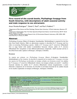
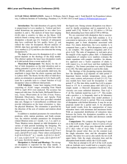
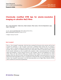
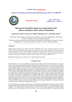
Home
Search
Collections
Journals
About
Contact us
My IOPscience
Non-contact Atomic Force Microscopy Simulations of Hydrogen-terminated Si(100) Surfaces
with a Methyl
This content has been downloaded from IOPscience. Please scroll down to see the full text.
2007 J. Phys.: Conf. Ser. 61 785
(http://iopscience.iop.org/1742-6596/61/1/157)
View the table of contents for this issue, or go to the journal homepage for more
Download details:
IP Address: 136.243.24.42
This content was downloaded on 06/02/2015 at 14:14
Please note that terms and conditions apply.
IOP Publishing
doi:10.1088/1742-6596/61/1/157
Journal of Physics: Conference Series 61 (2007) 785–789
International Conference on Nanoscience and Technology (ICN&T 2006)
Non-contact Atomic Force Microscopy Simulations of
Hydrogen-terminated Si(100) Surfaces with a Methyl
Akira Masago and Satoshi Watanabe
Department of Materials Engineering, The University of Tokyo, Hongo 7-3-1, Bunkyo-ku,
Tokyo, 113-8656, Japan
E-mail: [email protected]
Katsunori Tagami and Masaru Tsukada
Department of Nano-science and Nano-engineering, Waseda University, Waseda
Tsurumaki-cho 513, Shinjuku-ku, Tokyo, 162-0041, Japan
Abstract. Toward the development of a simulator of scanning probe microscope for systems
with adsorbed organic molecules, we simulate non-contact atomic force microscope images
of hydrogen-terminated Si(001)2×1 surfaces with an isolated methyl using a Si tip with and
without a hydrogen atom at the apex, using a density-functional based tight-binding method.
We examine the constant height, constant frequency and energy dissipation images. In addition
to normal images of constant height and constant frequency modes, we obtain the exotic energy
dissipation images, where a low dissipation spot is surrounded by a ring of high dissipation
region. These images can be understood from the site-dependence of force hysteresis.
1. Introduction
Recently, atomic force microscopy (AFM) has attracted much attention as a powerful tool for
high resolution observations, and has been investigated both experimentally and theoretically.
As a result, methodology of interpreting AFM images has been established for surfaces of
inorganic materials.[1, 2]
As for surfaces adsorbed with organic molecules, which have also attracted attention
increasingly, interesting experimental reports have already been reported. For example,
the topographic image of copper-phthalocyanine (CuPc) shows submolecular-scale contrast,
revealing the four-leaf structure of the CuPc.[3] Besides, larger energy dissipations are observed
at the inter-molecular spaces than at the site of molecule. In general, for the surfaces with
adsorbed organic molecules, our understanding on the relation between the observed AFM
images and structure of sample surfaces is still insufficient to understand interesting observed
results such as the above examples. In this situation, simulations are often helpful. Although
several such simulations have already been reported, most of them are simulations using classical
molecular dynamics (MD),[4, 5] which is insufficient: MD does not consider the effects of
electronic states, which are indispensable in some cases such as systems including the Si(001)
reconstructed surfaces.
Considering these situations, we are developing an AFM simulator for surfaces with organic
molecules. As the first step toward this, we have examined AFM images of an isolated methyl
© 2007 IOP Publishing Ltd
785
786
on the H-terminated Si(001) surface and the behavior of the methyl in the presence of the tip
in the present work.
2. Simulation method
We employ density-functional based tight-binding (DFTB) method,[6] and use the same
parameters as two of the authors had used in a previous report.[7] The Si(001)2×1 surface is
represented by a slab consisting of six Si layers, whose lateral size is 4×4. The periodic boundary
conditions are imposed only in the lateral directions. Only the front surface is reconstructed to
the 2×1 structure. The Si atoms of both surfaces are terminated by H atoms, and one of the H
atoms in the front surface is substituted by a methyl. The Si tip is modeled by a cluster of a
Si4 H9 molecule, which has a dangling bond toward the surface. Another tip where the dangling
bond at the apex is terminated by a H atom is also used, and hereafter we call the former
and latter simple Si tip and H-terminated Si tip, respectively. The effect of distortion due to
tip approach is considered by structural relaxation using the conjugated-gradient method. The
effect of phonon at finite temperature is not considered. During the structural relaxation, three
bottom layers of the surface and two bottom layers of the tip are fixed.
The frequency shift ∆ν and energy dissipation ∆E are calculated using the following
expressions[8]:
ν0
∆ν = −
2πAk
∆E = A
0
2π
0
2π
Fz (L + A cos θ) cos θdθ,
Fz (L + A cos θ) sin θdθ,
(1)
(2)
where ν0 , A and k are resonance frequency of the free cantilever, its amplitude and the cantilever
spring constant, respectively. The z-component forces Fz (L + A cos θ) are calculated by the
DFTB method. The long range van der Waals force is not considered in the present study.
In the present paper, we discuss the images of constant height and constant frequency modes
and the energy dissipation image. the constant height and dissipation images are obtained by
plotting ∆ν and ∆E under a constant tip-sample distance, respectively. Here, the tip-sample
distance is defined as the height difference between the nuclei of the tip apex atom and the top
of atom in the adsorbed methyl. In discussion of the constant height mode with the height of 2.3
˚
A, no hysteresis of force curve is assumed, because the adsorbed methyl is considered to distort
little at such a distance. In the constant frequency mode, the same assumption is imposed due
to the same reason.
3. Calculation results
3.1. Constant height and constant frequency shift images
We firstly discuss AFM images of the constant height mode. Figure 1 is the image obtained
for the minimum tip-sample distance of 0.0 ˚
A with the simple Si tip. Here, the amplitude of
cantilever vibration is 100 ˚
A, its spring constant is 48 N/m, and resonance frequency is 175 kHz.
We can recognize two remarkable spots in the images. The irregular dark spots at the upper
middle and at the lower right are created by the capture of a H atom by the tip. This spot is
considered to be an artifact caused by the small size of the tip mode, because H atom attaches
to one of the bottom atoms in the tip. On the other hand, the other spot around the adsorbed
methyl is a normal one reflecting features of the surface, though this spot is not necessary clear,
either. Figure 2 is the image obtained for the same distance with the H-terminated Si tip.
This image is clearer than Fig. 1, because bottom atoms of the tip are located farther from
the surface owing to the H atom at the tip apex. We can recognize a round spot around the
adsorbed methyl. However, this spot does not show symmetry reflecting the internal atomic
787
Figure 1. Constant height mode AFM image
on the H-terminated Si(001)2×1 surface with
an isolated methyl obtained using the simple
Si tip.
Figure 2. Constant height mode AFM image
on the H-terminated Si(001)2×1 surface with
an isolated methyl using the H-terminated Si
tip.
structure of the methyl. This absence of symmetric feature in spots can be understood from
flexibility of the methyl as discussed in our previous study,[9] where the forces between tip and
sample plotted at constant heights are examined.
Figure 3 is another constant height image, simulated for the minimum tip-sample distance of
2.3 ˚
A with the simple Si tip. Here, the amplitude of cantilever vibration is 65 ˚
A. This image is
clearer and shows symmetric feature reflecting internal structure of the adsorbed methyl, which
corresponds well to our previous study.[9] This is a consequence of suppression of the flexible
motion of the methyl. Figure 4 is the constant frequency image obtained with the simple Si
tip. Here, the preset value of the frequency shifts of -0.2 Hz is used. The amplitude, resonance
frequency and the spring constant are 50 ˚
A, 200 kHz and 20 N/m, respectively. This image
shows an oval spot around the adsorbed methyl. It is noted that the images created using a
H-terminated Si tip also look similar under any conditions. These images reflect anisotropy of
internal structure of the methyl, but their resolution is not so high. Considering the discussion
on Fig. 3, we guess that images with higher resolution can be obtained by suppressing the flexible
motion of the methyl. This can be realized by making the tip-sample interaction weaker, that
is, by using a smaller preset value of the frequency shift. However, the consideration of van
der Waals force is desirable in more detailed discussion, and this we do not try to get higher
resolution images in the present work.
3.2. Energy dissipation images
Figure 5 is a dissipation image obtained using the simple Si tip. The bright spots are at the
upper middle and at the lower right are artifacts similar to the dark spots seen in Fig. 1. The
most interesting feature seen in this image is the doughnut shape around the methyl, which is
seen only in the energy dissipation image. This means that the energy dissipation is small at
the center of doughnut. We did not expect this before doing simulation, because the methyl can
distort easily.
To clarify the origin of this feature, we investigate the tip-sample distance dependence of the
forces at the sites denoted by ”A”, ”B” and ”C” in Figs. 1 and 5. The force curves at these sites
are shown in Figs. 6. We found that the force curves at the sites on the doughnut ring (site ”A”
and ”C”) have hysteresis, while the force curve at the center of the doughnut (site ”B”) does
not. This result can be understood from the expression of (2): no force hysteresis causes zero
energy dissipation.
Then next question is why the hysteresis does not appear in the force curve in spite of the
788
Figure 3. Constant height mode AFM image
on the H-terminated Si(001)2×1 surface with
an isolated methyl using the simple Si tip. No
hysteresis assumption is imposed.
Figure 4. The constant frequency mode
AFM image on the H-terminated Si(001)2×1
surface with an isolated methyl using the
simple Si tip.
flexibility of the methyl. To answer this, we examine the behavior of the surface atoms in the
presence of the tip motion. The snapshot of the structural sequence at the site ”C” is shown in
Fig. 7. When the tip approaches the adsorbed methyl on the Si dimer from the original position
(C-1), the tip pushes the methyl into the surface (C-2). When the tip approaches further, the
methyl tilts suddenly (C-3) and consequently escapes from the stress of the tip approach. This
tilted state is maintained for a while in the refraction process, which causes the force hysteresis
and the energy dissipation. Finally, both tip and methyl return back to the original position
(C-4).
Next, the snapshot of the structural sequence at site ”B” is shown in Fig. 8. When the tip
approaches the adsorbed methyl on the dimer from the original position (B-1), the tip pushes
the methyl into the surface (B-2) as in the case of site ”C”. However, further approach of the
tip merely pushes the methyl and does not cause the sudden change of configuration (B-3). In
the retraction process, both tip and methyl smoothly return back to the original position (B-4).
In this way, the difference in the methyl motion causes the difference in the force hysteresis and
the energy dissipation.
5
A
B
C
Force (nN)
4
3
2
1
0
−1
Figure 5.
Energy dissipation image of
the H-terminated Si(001)2×1 surface with an
isolated methyl using the simple Si tip.
0
1
2
3
4
Tip−sample distance (Å)
Figure 6. The tip-sample distance dependence of the forces at the sites ”A”, ”B” and
”C” in the frequency shift (Fig. 1) and energy
dissipation (Fig. 5) images.
We expect that similar behaviors can be observed in the other systems with adsorbed
organic molecules. For example, the submolecular-scale contrast in topographic image and
789
Figure 7.
Snapshots of the surface
deformation during the AFM operation at the
tip-sample distance of 1.0 ˚
A (Approach: C2, Retract: C-3) and 2.0 ˚
A (Approach: C-1,
Retract: C-4) at the site ”C”.
Figure 8.
Snapshots of the surface
deformation during the AFM operation at the
tip-sample distance of 1.0 ˚
A (Approach: B2, Retract: B-3) and 2.0 ˚
A (Approach: B-1,
Retract: B-4) at the site ”B”.
large dissipation in the inter-molecule spaces of the CuPc mentioned previously[3] may be
understood in a similar manner as the images examined in the present study. It is should
be noted that the above results are obtained assuming zero temperature. To discuss the effects
of finite temperatures is an important future task.
Acknowledgments
This study is supported in part by the Japan Science and Technology Agency (JST) program
”Development of System and Technology for Advanced measurement and Analysis”. The
computation in this study has been done using the facilities of the Supercomputer Center,
Institute for Solid State Physics, The University of Tokyo.
References
[1]
[2]
[3]
[4]
[5]
[6]
[7]
[8]
[9]
L. Kantorovich and C. Hobbs, Phys. Rev. B 73, 245420 (2006).
N. Sasaki, S. Watanabe, and M. Tsukada, Phys. Rev. Lett. 88, 046106 (2002).
T. Fukuma, K. Kobayashi, H. Yamada, and K. Matsushige, J. Appl. Phys. 95, 4742 (2004).
B. Bat-Ul, S. Fujii, T. Shiokawa, T. Ohzono, and M. Fujihira, Nanotechnology 15, 710 (2004).
M. Harada, K. Tagami, M. Tsukada, to be submitted.
D. Porezag, T. Frauenheim, T. Kohler, G. Seifert, and R. Kaschner, Phys. Rev. B 51, 12947 (1995).
K. Tagami and M. Tsukada, Surf. Sci. 493, 56 (2001).
N. Sasaki and M. Tsukada, Jpn. J. Appl. Phys. 39, L1334 (2000).
A. Masago, S. Watanabe, K. Tagami, and M. Tsukada, e-J. Surf. Sci. Nanotech. 4, 197 (2006).


© Copyright 2026