
topair - Inicio
Manual de instalación, uso y mantenimiento.
Installation, use and maintenance manual.
R407C
RAC_QZ
RACPC_QZ
Enfriadoras de agua condensadas por
aire y bombas de calor aire-agua con
ventiladores centrífugos, compresores
herméticos y semiherméticos alternativos y grupo hidráulico integrado.
Water chillers air condensed and
heat pumps air to water with centrifugal fans, reciprocating hermetic
and semihermetic compressors and
integrated hydraulic group.
M_RAC_QZ/RACPC_QZ - 11/02
Manual de instalación, uso y mantenimiento
Installation, use and maintenance manual
RAC_QZ - RACPC_QZ
Notas -------------------------------------------
Notes --------------------------------------------
Gracias por la confianza depositada en TOPAIR, y felicitarle
por haber adquirido su nueva unidad.
Thank you for placing your trust in TOPAIR, and congratulations on buying a new unit.
Este manual le ayudará a realizar todas aquellas tareas más
primordiales para el buen funcionamiento de su unidad.
Siguiendo paso a paso todos los capítulos gozará de un
magnífico funcionamiento y le ayudará a resolver mejor las
eventuales paradas en servicio.
This manual will help you to carry out the most essential tasks
to ensure the correct running of your unit. By following each
chapter step by step it will work perfectly and it will help you to
solve occasional stoppages that occur while in operation.
So that their unit enjoys per many years of a good operation,
follow the installation, use and maintenance steps that are
described in this manual.
Para que su unidad goce por muchos años de un buen
funcionamiento, siga los pasos de instalación, uso y mantenimiento que se describen en este manual.
Your unit has been designed, studied and created under the
most rigorous of quality control conditions, there by complying
with 98/37/CE, 73/23/EEC and modification 2004/108/CE,
2005/32/CE, 97/23/CE European Community Directives and
earning the right to use the EC labelling. All of this is to satisfy
you as to its functioning, reliability and safety.
Su unidad ha sido diseñada, estudiada y creada bajo los más
rigurosos controles de calidad, cumpliendo con lo dispuesto
por las Directivas Europeas Comunitarias 98/37/CE,
73/23/CEE y su modificación 2004/108/CE, 2005/32/CE y
97/23/CE, disponiendo por tanto del marcaje CE. Todo esto
para satisfacerle en su funcionamiento, fiabilidad y seguridad.
All TOPAIR machines leave the factory after being tested,
filled with gas and oil, and checked using a strict quality
control throughout the manufacturing process, because of this
TOPAIR is not responsible for any negligent handling,
accidents, repairs or alterations of the product, which may
cause damage or operational faults in the machine, unless
there is consent in writing from TOPAIR.
Todas la máquinas de TOPAIR, salen de fábrica probadas,
cargadas de gas, aceite y verificadas bajo un estricto control
de calidad a lo largo de toda su fabricación, por lo cual
TOPAIR no se hace responsable por una manipulación
negligente, accidentes, reparación o alteraciones del producto, si no existe consentimiento por escrito de TOPAIR, los
cuales puedan ocasionar daños o un mal funcionamiento de
la máquina.
All the components that make up the unit that you have
bought, have been approved by their respective manufacturers, checked, put through trials, and tested by our Research
and Development department in conjunction with the Quality
Control department, apart from the final overall test on the test
bench.
Todos los componentes que monta la unidad que han
adquirido, han sido homologados por sus respectivos
fabricantes, verificados, ensayados y probados por nuestro
departamento de Investigación y Desarrollo junto al de
Calidad, a parte de su prueba final en conjunto en el banco de
pruebas.
However, there is a possibility that for reasons beyond our
control, certain elements may be defective or damaged for a
variety of reasons (transport, incorrect or negligent handling,
etc....)
Sin embargo existe la posibilidad de que por razones ajenas a
nuestro control, existan elementos, que después de salir la
unidad de fábrica, se encuentren deteriorados o dañados por
diversas razones (Transporte, manipulación indebida o
negligente, etc...)
For this reason and in the event of the unit suffering damage
or other problems, the unit should not be installed or put into
operation in conditions that are not specified in this manual.
Por esta razón y en caso de que la unidad sufriera algún
desperfecto o anomalía diversa, no se debe de someter a la
unidad a condiciones de instalación o funcionamiento, las
cuales no estén especificadas en este manual.
Although all steps have been taken to ensure that the
production of this manual is accurate and complete, TOPAIR
takes no responsibility for any error, memory lapse or
omission.
Aunque se han tomado todas las precauciones posibles, para
que la elaboración de este manual sea precisa y completa,
TOPAIR, no asume ninguna responsabilidad acerca de
cualquier error, olvido u omisión.
TOPAIR is engaged in a process of continual development in
order to improve the quality of its products and so reserves
the right to modify any design or technical information without
prior notice.
TOPAIR, en una constante evolución por mejorar la calidad
de sus productos, se reserva el derecho de modificar cualquier diseño o dato técnico sin previo aviso.
None of this edition may be reproduced, translated, saved in a
storage system or transmitted in any way or by any medium
be it electronic, mechanical, by photocopy, recording or by
any other means without the prior written consent of TOPAIR.
Ninguna parte de esta edición puede reproducirse, traducirse,
guardarse en un sistema de almacenamiento o transmitirse
de ninguna manera ni por ningún medio, sea electrónica,
mecánica, fotocopia, grabación o cualquier otro, sin previo
consentimiento por escrito de TOPAIR.
TOPAIR Aire Acondicionado, S.A.
M_RAC_QZ/RACPC_QZ - 11/02
2
Manual de instalación, uso y mantenimiento
Installation, use and maintenance manual
RAC_QZ - RACPC_QZ
Índice -------------------------------------------
Index ---------------------------------------------
0.- CONSIDERACIONES PREVIAS ........................... 4
0.- PREVIOUS CONSIDERATIONS ......................... 25
1.- INSTALACION....................................................... 4
1.- INSTALLATION................................................... 25
1.1 Recepción y descarga.
1.2 Situación e instalación.
1.3 Conexiones eléctricas.
1.4 Conexiones hidráulicas.
1.5 Conexiones a conductos.
1.1
1.2
1.3
1.4
1.5
2.- USO Y PUESTA EN MARCHA.............................. 6
2.- USE AND START-UP THE UNIT ........................ 27
2.1 Comprobaciones preliminares a la puesta en
marcha.
2.2 Puesta en marcha y comprobación de
funcionamiento.
2.1 Preliminary verifications to the start-up of the
unit.
2.2 Start-up and checking the units
performance.
3.- REGULACIONES .................................................. 8
3.- REGULATIONS................................................... 29
3.1 Graduación de los controles.
3.2 Condiciones normales de funcionamiento.
3.3 Límites de funcionamiento.
3.1 Graduations of the controls.
3.2 Normal operational conditions.
3.3 Operational limits.
4.- NORMAS ............................................................... 9
4.- SAFETY REGULATIONS.................................... 30
4.1 Normas de seguridad.
4.1 Safety regulations.
5.- MANTENIMIENTO ORDINARIO ......................... 10
5.1
5.2
5.3
5.4
Discharge and reception.
Situation and installation.
Electrical connections.
Hydraulic connections.
Ducts connections.
5.- NORMAL MAINTENANCE.................................. 31
Una vez a la semana.
Una vez al mes.
Una vez al año.
Operación parada prolongada.
5.1
5.2
5.3
5.4
Once a week.
Once a month.
Once a year.
Lingering stop of the unit.
6.- MANTENIMIENTO EXTRAORDINARIO ............. 11
6.- EXTRAORDINARY MAINTENANCE .................. 32
7.- PIEZAS DE REPUESTO ACONSEJADAS ......... 16
7.- RECOMENDED SPARE PARTS......................... 37
8.- SERVICIO TECNICO........................................... 16
8.- TECHNICAL SUPPORT ...................................... 37
8.1 Contrato de Mantenimiento.
8.1 Contract of maintenance.
9.- CROQUIS Y TABLAS ......................................... 17
9.- GRAPHICS AND TABLES .................................. 17
9.1
9.2
9.3
9.4
Sistemas de elevación.
Pesos y presiones sonoras.
Espacios mínimos requeridos.
Consumos eléctricos y secciones de cables
recomendadas.
9.5 Instalación eléctrica.
9.6 Limites de funcionamiento.
9.1
9.2
9.3
9.4
Loading and unloading system
Weight and sound level.
Required minimum spaces.
Electrical consumption and recommended
sections.
9.5 Electrical installation.
9.6 Operational limits.
TOPAIR Aire Acondicionado, S.A.
M_RAC_QZ/RACPC_QZ - 11/02
3
Manual de instalación, uso y mantenimiento
Installation, use and maintenance manual
RAC_QZ - RACPC_QZ
0.- Consideraciones Previas.
Antes de realizar la puesta en marcha de la unidad, lea
atentamente este Manual de Instalación, Uso y Mantenimiento, y el Manual de Regulación de la unidad.
"
Ver las tablas de PESOS DE LA UNIDADES en
página 18.
1.- Instalación.
" Se debe prever en las cercanías del aparato un sifón,
! La responsabilidad de TOPAIR se limita al suministro de
para el drenaje del agua de la instalación, necesario cuando
se ejecutan las operaciones de mantenimiento.
la unidad. Su instalación debe ser realizada según las
presentes instrucciones y las normas de la profesión, por
personal cualificado, asignado al nombre de empresas aptas
para asumir la entera responsabilidad del montaje de la
instalación.
1.3 Conexiones eléctricas:
Verificar el cableado eléctrico de la unidad, asegurándose
que no existe ninguna desconexión a causa de las vibraciones del transporte.
1.1 Recepción y descarga:
Las enfriadoras de agua y bombas de calor con grupo
hidráulico integrado TOPAIR están desarrolladas y previstas
para que su carga y descarga se realice mediante carretilla.
La sección de la línea trifásica deberá ser elegida y dimensionada de modo que no exista una excesiva caída de tensión,
teniendo en cuenta para ello la longitud de la línea y el
consumo de la unidad.
"
"
" Evitar, en la forma más absoluta, las posiciones muy
En todo caso, el cableado de la obra deberá estar de acuerdo
con las normas y reglamentos locales.
Ver gráficos de SISTEMAS DE ELEVACIÓN en
página 17.
Ver tabla de CONSUMOS ELECTRICOS Y SECCIONES ACONSEJADAS en páginas 20 y 21.
inclinadas y los golpes violentos.
La línea de suministro eléctrico deberá estar protegida con un
diferencial.
" La unidad deberá inspeccionarse, si es posible, en
El enganche eléctrico necesario se reduce a efectuar la
conexión de las tres fases y neutro en el interruptor general,
la conexión de toma de tierra en las clemas situadas a tal
efecto en el interior del cuadro eléctrico y el interruptor de
mando para la puesta en marcha de la unidad. (Este último si
la unidad lo requiere).
presencia del transportista, inmediatamente después de ser
recibida, para comprobar cualquier posible daño de transporte. Cualquier daño observado, por pequeño que parezca, se
deberá hacer constar por escrito al transportista en el albarán
de entrega y antes de 24 horas desde la recepción ponerlo en
conocimiento de TOPAIR para poder efectuar posteriormente
las oportunas reclamaciones. El incumplimiento de lo
anteriormente indicado dará lugar a la no aceptación por
parte de TOPAIR de los daños que se hayan podido producir
en el transporte.
#
No poner en marcha la unidad cuando exista un
desequilibrio de fases superior a 2%
1.4 Conexiones hidráulicas:
1.2 Situación e instalación:
Todas las tuberías de agua deberán aislarse térmicamente y
ser soportadas de forma que ningún peso descanse sobre la
unidad.
Estas unidades han sido diseñadas para su instalación en
interior. No instalar la máquina en zonas con atmósfera
potencialmente explosiva. Alrededor de la unidad se dejará el
espacio libre suficiente para permitir al personal que cumpla
las necesarias operaciones de mantenimiento y permitir la
libre circulación del aire en la entrada de la máquina.
Siempre debe ser evitada la recirculación de aire.
Instalar válvulas de purga de aire automáticas ó manuales en
los puntos altos del circuito y drenajes en los puntos bajos
para permitir el vaciado, instalar termómetros y válvulas de
cierre junto a las conexiones de entrada y salida de agua; en
caso de existir partículas en el agua capaces de obstruir el
intercambiador de calor, colocar a la entrada de la máquina
un filtro con una luz de maya alrededor de 1,2 mm y una
válvula de llenado. Para evitar vibraciones, ruido o una
posible rotura de la tubería se recomienda montar manguitos
o conexiones elásticas.
" Ver gráficos sobre ESPACIOS MINIMOS REQUERIDOS en página 19.
Resulta aconsejable colocar la unidad sobre una plancha de
caucho o similar para evitar problemas de transmisión de
vibraciones.
En todo caso las tuberías deben estar de acuerdo con las
normas y reglamentos locales.
Asegurarse que, tanto el suelo como la estructura que lo
soporta, son suficientes para aguantar el peso en funcionamiento de la unidad completa.
TOPAIR Aire Acondicionado, S.A.
M_RAC_QZ/RACPC_QZ - 11/02
4
Manual de instalación, uso y mantenimiento
Installation, use and maintenance manual
RAC_QZ - RACPC_QZ
" Dependiendo de las condiciones atmosféricas en la
PRESION/CAUDAL BOMBAS
kPa
(5)
300
zona puede ser necesario la protección contra la congelación
pudiéndose realizar esta añadiendo etilenglicol en concentración adecuada para proteger la instalación hasta una temperatura de 5º C por debajo de la mínima temperatura posible
en el lugar de instalación.
280
(6)
(4)
(1)
260
(3)
240
(2)
220
200
Para la instalación de equipos auxiliares deberá tenerse en
cuenta los caudales mínimos y máximos posibles de funcionamiento.
180
160
140
1.4.1 Grupo hidráulico integrado:
120
100
Tal como se aprecia en el dibujo, el grupo hidráulico está
compuesto por: moto bomba de circulación de tipo centrífugo,
vaso de expansión cerrado de tipo membrana, presostato
diferencial como seguridad frente a la falta de flujo de agua,
manómetro de agua, válvula de seguridad a 3 bar, válvula de
evacuación de aire, válvula reguladora, drenaje y sensores de
temperatura en entrada y salida de agua.
80
60
0,2
1,0
5,0
Q(dm3 /s)
(1) 081
(2) 101 - 121
(3)141 - 151B - 162
(4) 201B - 202
(5) 242 - 251B
(6) 282 - 302B
Si el sistema tiene una pérdida de carga excesiva respecto a
la generada por la bomba, el caudal será bajo y la diferencia
de temperaturas entre entrada y salida resultará ser mayor de
7ºC. Para reducir estas pérdidas, es necesario reducir las
pérdidas de cargas individuales (curvas, cambios de nivel,
accesorios, etc.), utilizando un diámetro de tubería lo suficientemente dimensionado y evitando grandes recorridos. La
presión del circuito hidráulico debe situarse entre 0,5 y 1 bar.
1.4.3 Volumen máximo del circuito de agua:
Estas unidades incorporan un vaso de expansión cuya misión
es la de mantener constante la presión del sistema al permitir
que se expansione el agua cuando aumenta su temperatura.
1.4.2 Control del Caudal de Agua:
Los grupos hidráulicos disponen de bombas de circulación de
agua que cubren las posibles necesidades de caudal para las
diversas diferencias entre la entrada y salida de agua a plena
carga que pueden oscilar entre 4 y 7ºC. Esta diferencia de
temperaturas determina el caudal de agua del sistema y
puede ser controlado mediante la válvula de regulación (VR)
existente en la tubería de salida del módulo hidráulico. Para
controlar el caudal de agua procederemos de la siguiente
manera:
La tabla siguiente da el volumen máximo del circuito.
Modelos
Abriremos totalmente la válvula (VR), arrancaremos la bomba
de agua y la dejaremos que funcione durante al menos 1 hora
para limpiar el circuito de agua del sistema. Pasado este
tiempo, limpiaremos el filtro y seguidamente con la bomba en
funcionamiento leeremos en el manómetro la diferencia de
presión existente entre la entrada y la salida de la bomba.
Comprobaremos en la información técnica el caudal de agua
nominal y leeremos sobre la curva de presión/caudal de las
bombas. La presión a la que nos da el caudal necesario,
seguidamente iremos cerrando la válvula de regulación (VR)
hasta conseguir la diferencia de presión necesaria para
obtener el caudal nominal.
Volumen Máximo en
litros
081
275
101,121,141
440
151B,162,201B
660
202,251B,242,282,302B
990
En caso de que la instalación presente un volumen mayor, se
deberá incorporar el vaso de expansión necesario.
1.5 Conexiones a conductos:
El instalador debe realizar el cálculo de los conductos, que
deben instalarse en la impulsión de todos los ventiladores, en
función del caudal y la presión disponible, evitando en su
realización los cambios bruscos de dirección que pueden
crear perdidas de carga puntuales. La situación de las rejillas
de impulsión y aspiración debe ser seleccionada con el fin de
evitar la recirculación del aire, así como la producción y
transmisión de ruidos.
TOPAIR Aire Acondicionado, S.A.
M_RAC_QZ/RACPC_QZ - 11/02
5
Manual de instalación, uso y mantenimiento
Installation, use and maintenance manual
RAC_QZ - RACPC_QZ
2.- Uso y puesta en marcha.
#
!
ATENCION:
Un caudal incorrecto puede provocar mal funcionamiento y
rotura del intercambiador. Comprobar que el caudal es
constante y está dentro de los límites máximos y mínimos
indicados en la información técnica de la unidad.
ATENCION:
Cualquier máquina fabricada por TOPAIR sólo puede ser
manipulada por personal cualificado.
2.1 Comprobaciones preliminares a la puesta en marcha:
h) Verificar que el cartón de protección de batería se ha
quitado cuando se ha completado la instalación de la
máquina y se procede a la puesta en marcha.
" Todas las unidades TOPAIR salen de fábrica con su
correspondiente carga de gas y aceite (ver placa de características). Antes de poner en marcha la unidad, observar el
aspecto visual del circuito frigorífico. Si por motivos ajenos
(transporte, manipulación indebida...otros...) al poner en
marcha la unidad se detectan síntomas de pérdida de
refrigerante, como presostato de baja disparado o pérdida de
rendimiento en la unidad, hacer una prueba de fugas en el
circuito.
i) Comprobar el anclaje de compresores, motores y ventiladores, y sentido de giro de estos, siendo en los centrífugos
como se indica en la figura, comprobando la expulsión del
aire hacia el exterior de la máquina.
# a) Con la máquina bajo tensión y tras cerrar el interruptor general y el automático de seguridad, tener el calentador
de cárter conectado, por lo menos, desde ocho horas antes
de la puesta en marcha, y comprobar su funcionamiento. La
temperatura de aceite deberá ser de 10ºC superior a la de
ambiente.
j) El volumen de agua contenido en la instalación no debe
ser inferior al 10% del caudal de agua en circulación en
una hora:
VOLUMEN DE AGUA INSTALACION (L) = 360 x CAUDAL
DE AGUA EN CIRCULACION (l/s)
b) Abrir todas las válvulas de paso de refrigerante de la
unidad.
# LA NO COMPROBACION Y SEGUIMIENTO DE LAS
c) Abrir todas las purgas de las líneas de agua. Abrir todas las
válvulas de paso de agua al intercambiador y asegurarse
que cuando se pongan en marcha la bomba, podrá pasar
el agua. Comprobar en el manómetro que la presión de
agua en el circuito está entre 1 y 2 bar.
ANTERIORES OPERACIONES Y SI COMO CONSECUENCIA OCASIONARAN DAÑOS EN LAS MAQUINAS, PODRIA
DAR LUGAR A LA ANULACION DE LA GARANTIA.
2.2 Puesta en marcha y comprobación de funcionamiento:
d) Comprobar que la tensión en la línea de suministro de
energía eléctrica esta equilibrada y, es la misma que indica
la placa de características, o con una variación máxima de
+/- 10% y un desequilibrio entre fases de un máximo de
2%.
Seleccionar un ciclo de trabajo (Unidades bomba de calor) o
cerrar el interruptor de mando y comprobar que la bomba de
agua se encuentra funcionando y que circula el agua.
Verificar el correcto funcionamiento de la cadena de enclavamientos, en especial el interruptor de flujo. Si el regulador
demanda funcionamiento de compresor, éste arrancará tras
la/s correspondientes temporizaciones.
" ATENCION: No podrá aplicarse la garantía si el grupo
ha sido conectado a una tensión de alimentación distinta a la
especificada en la confirmación de pedido o la alimentación
eléctrica proceda de grupos electrógenos.
" ATENCION: Antes de cambiar el ciclo de funcionamien-
e) Con el interruptor general de fuerza en posición abierta,
comprobar que los contactores de compresores, ventiladores y bomba se pueden mover libremente con la mano, sin
ningún entorpecimiento, y que los contactos estén libres de
polvo y suciedad. Comprobar que los fusibles e interruptor
automático están instalados y que el regulador de capacidad está ajustado por debajo de la temperatura de entrada
de agua. Volver a cerrar el interruptor general.
to, deberá asegurarse que la unidad ha parado, para lo cual
debe situar el interruptor de mando en la posición de PARO
"0".
A) Ciclo de producción de agua caliente. (Bomba de calor).
Como el supuesto de que las condiciones de aire exterior
sean bajas (inferior a 8ºC) y el agua del circuito de climatización esté fría (temperatura inferior a 20ºC) circunstancia
frecuente en cualquier instalación, al hacer la puesta en
marcha o que permanezca parada cierto tiempo (caso del fin
de semana) con estas temperaturas o con temperaturas
inferiores, a este tipo de unidades les resulta difícil o imposible el levantar la temperatura de condensación y funcionar
correctamente.
f) Comprobar que el compresor tiene la cantidad adecuada
de aceite. El nivel debe cubrir aproximadamente 1/2 del
visor de aceite.
g) Poner en marcha la bomba de agua, ver si funcionan
correctamente y dan el caudal adecuado de forma constante. Verificar el funcionamiento del interruptor de flujo de
agua.
TOPAIR Aire Acondicionado, S.A.
M_RAC_QZ/RACPC_QZ - 11/02
6
Manual de instalación, uso y mantenimiento
Installation, use and maintenance manual
RAC_QZ - RACPC_QZ
Por todo ello, las unidades disponen de un termostato límite
de temperatura, que impide el funcionamiento de los compresores cuando la temperatura de retorno del agua caliente a la
máquina es inferior a 20ºC, por ello debe incorporarse un
calderín eléctrico, u otro sistema, para precalentar el agua
hasta esta temperatura.
Presostato diferencial de aceite (Solo en modelo 251B):
Con los fusibles del compresor quitados, dar orden de puesta
en marcha de la unidad, con lo que, pasados 120 s desde
que cerró el contactor del compresor, éste debe de abrir a
causa del presostato diferencial de aceite. En caso contrario,
sustituir el presostato.
El proceso para la puesta en marcha será el siguiente.
Colocar el conmutador de mando en la posición de calor y
comprobar que la bomba de agua se encuentra funcionando y
que circula el agua por el condensador, con lo cual, pasados
cinco minutos, la unidad se pondrá en funcionamiento,
siempre que la temperatura del agua esté por encima de 20ºC
y por debajo del ajuste del regulador de temperatura de agua
caliente.
# Nivel de aceite: Se deberá tener un cuidado especial
en mantener el nivel de aceite. En cuanto se note una
disminución del nivel, antes de añadir eventualmente más,
déjese funcionar sin interrupción el compresor 3 o 4 horas,
controlando el nivel cada media hora.
Resulta imprescindible que la unidad disponga del tiempo
suficiente, para elevar la temperatura del agua del circuito,
antes de poner en funcionamiento los elementos de emisión
de calor como climatizadores, fan-coil, etc...
Es recomendable el conectar un termostato en la salida de
agua de la unidad, ajustado aproximadamente a 7ºC por
debajo de la temperatura de diseño de agua caliente, estando
inoperantes los elementos de emisión de calor, hasta que se
haya satisfecho el punto de ajuste del termostato. Este
sistema no debe de operar cuando la máquina funcione en
producción de agua fría.
B) Ciclo producción de agua fría.
Cerrar el interruptor de mando (Unidades RAC_QZ) o colocar
el conmutador de mando en posición de frío (Unidades
RACPC_QZ) y comprobar que la bomba de agua se encuentra funcionando y que circula el agua por el evaporador.
Pasados cinco minutos, la unidad se pondrá en funcionamiento, siempre que el regulador de capacidad esté ajustado por
debajo de la temperatura de entrada de agua.
Una vez realizada la puesta en marcha, se deberá comprobar
el funcionamiento de todas las protecciones, asegurándose
que cada una de ellas interrumpe el circuito de control y se
detiene el compresor. Los valores de regulación de cada
control están reseñados en el punto siguiente.
Presostato de alta: En ciclo de frío tapar la batería condensadora o poner en marcha el circuito con los fusibles del
ventilador quitados y observar simultáneamente el manómetro colocado en el lado de alta. La presión se elevará y el
compresor parará cuando la presión de descarga alcance la
fijada previamente en el presostato de alta. Si el compresor
no para, desconectar inmediatamente el interruptor de mando
y cambiar el presostato.
# NOTA: Tener en cuenta que siempre que actúe la
protección de alta, si no se pulsa el botón de rearme manual
colocado en el presostato, no arranca de nuevo el compresor.
Presostato de baja: Cerrar poco a poco la válvula de
aspiración del compresor, hasta que la presión alcance el
valor de corte. Si el compresor no para, abrir la válvula de
aspiración, desconectar el interruptor de mando y examinar
detenidamente el presostato, teniendo en cuenta que puede
haber una obstrucción o ser defectuoso.
TOPAIR Aire Acondicionado, S.A.
M_RAC_QZ/RACPC_QZ - 11/02
7
Manual de instalación, uso y mantenimiento
Installation, use and maintenance manual
RAC_QZ - RACPC_QZ
3.- Regulaciones.
3.3 Límites de funcionamiento:
REGULACION, CONDICIONES Y LIMITES DE FUNCIONAMIENTO
# IMPORTANTE: Estas unidades no pueden funcionar en
3.1 Graduación de los controles:
caso de nevada, ya que se puede producir el taponamiento
instantáneo de las baterías exteriores y provocar averías de
compresor, no estando cubiertas éstas por nuestra garantía.
Presostatos de baja y alta:
Lado de baja presión:
Rearme automático.
Presión de corte: .............................................................. 3 bar.
Presión de reenganche: ................................................... 4 bar.
Lado de alta presión:
Rearme manual (Actuando sobre el presostato)
Presión de corte: ............................................................ 27 bar.
Presión de reenganche: ................................................. 21 bar.
" Ver tabla sobre LIMITES DE FUNCIONAMIENTO en
página 24.
Nota: En caso de coincidencia o proximidad de dos o más de
los límites, puede producirse la intervención de las protecciones de la máquina.
Sistema de regulación o sistema de parcialización:
Rearme automático.
Graduación conforme a las características para las cuales ha
sido construida la unidad. Regulable según las necesidades.
Temperatura entrada agua fría en ciclo de frío:...............12º C.
Temperatura salida agua fría en ciclo de frío:....................7º C.
Temperatura entrada agua caliente en ciclo de calor: .... 40º C.
Temperatura salida agua caliente en ciclo de calor:........45º C.
# IMPORTANTE: La modificación de cualquiera de estos
ajustes de fábrica, sin autorización escrita por parte de
TOPAIR, anulará inmediatamente la garantía.
Regulación antihielo:
Rearme automático.
Temperatura de corte:...................................................... 4º C.
Temperatura de reenganche:...........................................11º C.
Relé de desescarche: (Unidades bomba de calor)
Funcionamiento automático.
Temperatura inicio de desescarche: ....................... -2 / -1º C.
Temperatura final de desescarche:..........................20 a 26º C.
Tiempo mínimo entre dos desescarches: .....................30 min.
Tiempo máximo duración desescarche: ........................10 min.
Termostato límite: (Unidades bomba de calor)
Rearme automático.
Temperatura de corte:......................................................18º C.
Temperatura de reenganche:...........................................20º C.
Termostato limite temperatura descarga:
Funcionamiento automático.
Temperatura de corte:....................................................120º C.
Presostato diferencial de aceite:
(Solo en modelo 251B)
Rearme manual actuando sobre botón del presostato.
Presión diferencial de corte:........................................... 0,7 bar
3.2 Condiciones normales de funcionamiento:
Verano
Invierno
Presión normal lado de alta: ........ 13 a 26 bar....... 13 a 26 bar.
Presión normal lado de baja: ........ 4 a 6 bar........... 1,5 a 6 bar.
TOPAIR Aire Acondicionado, S.A.
M_RAC_QZ/RACPC_QZ - 11/02
8
Manual de instalación, uso y mantenimiento
Installation, use and maintenance manual
RAC_QZ - RACPC_QZ
4.- Normas.
4.1.NORMAS DE SEGURIDAD CONFORME A LA DIRECTIVA EUROPEA 98/37/CE.
La máquina cumple con la Directiva Europea de Baja Tensión
y el Reglamento Electrotécnico de Baja Tensión, por lo que
está equipada con los medios suficientes para prevenir los
riesgos eléctricos. Todas las máquinas disponen de una toma
de puesta a tierra para eliminar el riesgo de electricidad
estática, y contactos eléctricos indirectos siempre que la línea
tenga interruptor diferencial.
! La instalación y manejo de máquinas de climatización y
equipos de aire acondicionado, siempre entraña un peligro,
debido, entre otras, al circuito a presión de la unidad, transmisiones mecánicas y utilización de componentes eléctricos.
# Las zonas calientes como la parte de alta presión del
compresor y la línea de descarga, se señalizan con carteles
indicativos del riesgo por alta temperatura.
# Todas las operaciones a realizar en las máquinas han
de ser realizadas por personal cualificado.
La máquina se diseña y construye con materiales de resistencia al fuego suficiente para evitar el riesgo de incendio o
de sobrecalentamiento provocado por la propia máquina o los
productos utilizados por ella. Las válvulas de seguridad contra
sobre-presiones protegen la máquina contra riesgo de
explosión por exceso de presión
Las máquinas están diseñadas para que su regulación y
mantenimiento se lleven a efecto sin que las personas se
expongan a riesgo alguno, cuando las operaciones se
realizan en las condiciones previstas por el fabricante. Para
suprimir los riesgos de accidente que puedan resultar de
situaciones anormales previsibles, utilizamos carteles de
señalización de zonas con indicaciones del tipo:
Una vez realizada la instalación de la máquina, esta debe
estar protegida por una carcasa, conducción o rejilla que
impida el acceso a los rodetes de los ventiladores.
…………………………. - No tocar, tensión eléctrica.
En el presente manual se encuentran las tablas de pesos y
presión sonora de las unidades.
………………………..…………….- Alta temperatura.
La máquina de serie no puede utilizarse en atmósferas
potencialmente explosivas.
………….... - Peligro por transmisiones mecánicas.
La máquina se diseña para que no existan riesgos al realizar
las operaciones de limpieza y desagüe, aún en funcionamiento. Los drenajes están en el exterior, con lo que las purgas
pueden hacerse sin ningún riesgo.
……………...……….- Peligro por objetos cortantes.
En la placa de características de la máquina se refleja,
además de los datos principales según norma UNE 86-60285, el marcado "CE" de la unidad.
……..…. - Manipulación por personal cualificado.
- No pasar sin desconectar interruptor general
antes de cualquier manipulación.
La puesta en marcha de la máquina sólo se puede efectuar
por la acción voluntaria ejercida sobre el interruptor de
mando, estando cerrado el interruptor general. La parada
normal se realiza de forma segura actuando sobre el interruptor de mando o sobre el interruptor general (este segundo, en
caso de emergencia).
# El acceso a cualquier punto o elemento de la máquina,
para su manipulación, mantenimiento, etc., debe hacerse con
el interruptor general abierto.
Los componentes que trabajan a presión cumplen con la
directiva 97/23/CE de equipos a presión, por lo que se les
considera aptos para soportar las tensiones a que se ven
sometidos, eliminando así el riesgo de rotura en servicio.
! Siempre que se efectúe una intervención o reparación
en la máquina deberá de utilizarse una vestimenta y complementos adecuados, como gafas, guantes, mascarillas, etc.,
para evitar en la mayor parte posible los riesgos de un
accidente.
TOPAIR Aire Acondicionado, S.A.
M_RAC_QZ/RACPC_QZ - 11/02
9
Manual de instalación, uso y mantenimiento
Installation, use and maintenance manual
RAC_QZ - RACPC_QZ
5.- Mantenimiento ordinario.
Comprobaciones mínimas exigidas por el fabricante:
5.1 Una vez a la semana:
- Limpiar la batería condensadora. Puede utilizarse el lavado
a chorro de agua, con una manguera a presión. Hay que
tener la precaución de hacer el lavado de dentro a fuera.
- Comprobación de los niveles de gas, aceite, etc.
5.4 Operación parada prolongada:
- Verificar el nivel de aceite con el compresor en marcha. El
nivel debe cubrir la mitad del visor del aceite. En cuanto se
note una disminución del nivel antes de añadir eventualmente más, déjese funcionar sin interrupción el compresor
3 o 4 horas, controlando el nivel de aceite cada media
hora.
Previamente a una parada prolongada de la unidad, se
deberán realizar las siguientes operaciones:
- Los compresores se llenan de aceite inicialmente en
fábrica. La cantidad de aceite requerida para un segundo
llenado, por ejemplo, después de la completa descarga de
aceite, puede verse en la documentación técnica.
- Si la temperatura ambiente del lugar donde se encuentra la
unidad puede descender por debajo de 0º C, se debe
vaciar el agua contenida en el intercambiador, así como
desconectar la tubería de llenado de la instalación. El
intercambiador no se vacía totalmente por sí mismo, habrá
que actuar sobre el tapón de vaciado de agua. También se
puede eliminar el peligro de congelación haciendo circular
por la planta una solución de producto anticongelante.
! Se debe emplear solamente el aceite:
- El mismo proceso deberá seguir la bomba de agua,
tuberías, etc. que estén expuestas a bajas temperaturas.
* POLIOLESTER 160 PZ para compresores MANEUROP.
* ICI EMKARATE RL-32S o PLANETELF ACD 32 para
compresores FRASCOLD.
* MOBIL EAL ARCTIC 46 para compresores DORIN.
- Controlar todas las válvulas, tubos, circuito frigorífico en
general y limpiar eventualmente los filtros de agua.
- Abrir el interruptor general de corriente y retirar los fusibles
o desconectar los interruptores automáticos.
" Atención, USAR REFRIGERANTE R-407C.
- Verificar que no existan fugas de refrigerante.
- Verificar todos los puntos de corrosión, para limpiarlos y
pintarlos.
- Inspeccionar totalmente la instalación para asegurarse que
no existen condiciones anormales de funcionamiento.
Además de las instrucciones establecidas por el fabricante,
se deberán cumplir el resto de normas que le sean de
aplicación.
- Lectura y anotación de consumos eléctricos y tensión de
alimentación.
5.2 Una vez al mes:
- Comprobar las temperaturas de entrada y salida del aire y
del agua.
- Comprobar temperaturas de condensación y evaporación.
- Comprobar la tensión de las correas en unidades.
- Comprobación del tarado de todos los elementos de
seguridad y funcionamiento de los automatismos.
- Comprobar pérdidas de carga en el intercambiador de
agua.
5.3 Una vez al año:
- Controlar los contactos eléctricos de los contactores de los
motores.
- Controlar las válvulas, tubos, etc. y limpiar los filtros de
agua.
- Verificar y reapretar todas las conexiones eléctricas.
- Comprobar el estado y alineación de correas y poleas.
- Comprobar el estado de los cojinetes del motor del
ventilador y engrasar si fuera necesario.
- Comprobar el estado del aceite del compresor.
TOPAIR Aire Acondicionado, S.A.
M_RAC_QZ/RACPC_QZ - 11/02
10
Manual de instalación, uso y mantenimiento
Installation, use and maintenance manual
RAC_QZ - RACPC_QZ
6.- Mantenimiento extraordinario.
Los motivos por los cuales en el curso del servicio normal la
unidad puede pararse, son diversos. A continuación damos
una lista de las posibles causas, motivos y soluciones a
adoptar:
AVERIA
A.- El ventilador y/o el
compresor no funcionan.
ANOMALIA NOTADA
CAUSAS PROBABLES SOLUCIONES
1.- No llega tensión a los terminales
del compresor.
1.- Interruptor general abierto o
fusibles flojos o fundidos
1.- Cerrar, rearmar
automáticos. Comprobar fusible.
2.- Tensión normal en los terminales
del motor del compresor, pero el
motor no gira.
2.- Motor quemado o agarrotado.
2.- Sustituir.
3.- Contacto de uno de los automatismos de seguridad abiertos.
3.- El automatismo ha saltado.
3.- Rearmar.
4.- Interruptor de flujo abierto.
4.- Falta caudal de agua.
4.- Verificar el caudal
de agua y ajustar.
5.- Interruptor de mando en posición
abierta.
B.- La bomba de agua
no funciona.
5.- Colocar en posición de marcha.
1.- No llega tensión a los terminales
de la bomba.
1.- Interruptor general abierto o
fusibles flojos o fundidos.
1.- Cerrar, rearmar
automáticos. Comprobar fusible.
2.- Tensión normal en los terminales
del motor de la bomba, pero el motor
no gira.
2.- Bomba agarrotada o motor
quemado.
2.- Intentar girar
manualmente sin
tensión o sustituir.
3.- Relé térmico abierto.
3.- Exceso de consumo.
3.- Rearmar y verificar.
TOPAIR Aire Acondicionado, S.A.
M_RAC_QZ/RACPC_QZ - 11/02
11
Manual de instalación, uso y mantenimiento
Installation, use and maintenance manual
RAC_QZ - RACPC_QZ
6.- Mantenimiento extraordinario.
AVERIA
C.- El compresor se
para o no funciona.
ANOMALIA NOTADA
CAUSAS PROBABLES SOLUCIONES
1.- El presostato de alta presión salta
desconectándose.
1.- Ver apartado I.
1.- Ver apartado I.
2.- El presostato de baja presión
salta desconectándose.
2.- Ver apartado L.
1.- Ver apartado L.
3.- Protección interna del compresor
abierta.
3.- a.- Tensión demasiado baja.
3.- a.- Reclamar a la
compañía suministradora de energía
eléctrica.
b.- Absorción eléctrica excesiva
debida a una temperatura de
condensación demasiado elevada.
D.- El compresor se
para y arranca continuamente.
b.- Ver apartado I.
c.- Temperatura de descarga
excesiva.
c.- Falta gas refrigerante.
4.- El rendimiento del compresor no
se adapta a la instalación.
4.- El dispositivo de parcialización
no funciona.
4.- Reparar o sustituir.
5.- La protección antihielo salta
desconectándose.
5.- a.- El caudal de agua en el
evaporador ha disminuido.
5.- a.- Controlar el
caudal de agua del
evaporador.
b.- El dispositivo de parcialización no funciona.
b.- Repararlo o
sustituirlo.
6.- El control de presión de aceite
salta desconectándose.
6.- Ver apartado F.
6.- Ver apartado F.
1.- Funcionamiento normal pero hay
paros y arranques demasiado frecuentes por la intervención del presostato de baja.
1.- a.- Falta de refrigerante
1.- a.- Buscar y eliminar la fuga de refrigerante. Recargar.
b.- El diferencial del presostato
de baja tiene un intervalo muy
limitado.
c.- Falta caudal de agua.
b.- Sustituir el
presostato.
c.- Limpiar filtros
de agua y verificar el
caudal.
2.- Sustituir el filtro.
2.- Presión de aspiración demasiado
baja y escarcha sobre el filtro.
2.- Filtro de líquido obstruido.
E.- El compresor funciona ininterrumpidamente.
1.- El compresor es ruidoso, la presión de alta es demasiado baja y la
aspiración demasiado elevada.
1.- Partes internas del compresor
defectuosas.
1.- Sustituir o reparar
el compresor.
F.- Bajo nivel de aceite
en el compresor.
1.- El nivel de aceite disminuye
gradualmente.
1.- Bajo recalentamiento.
1.- Ajustar recalentamiento.
2.- Pérdida de aceite, nivel de aceite
muy bajo.
2.- Las juntas del cárter pierden
aceite o aceite insuficiente.
2.- Reparar y establecer el correcto nivel
de aceite.
TOPAIR Aire Acondicionado, S.A.
M_RAC_QZ/RACPC_QZ - 11/02
12
Manual de instalación, uso y mantenimiento
Installation, use and maintenance manual
RAC_QZ - RACPC_QZ
6.- Mantenimiento extraordinario.
AVERIA
G.- El compresor hace
ruido.
H.- La instalación tiene
un rendimiento inferior
al normal.
ANOMALIA NOTADA
1.- Los tubos de aspiración están
anormalmente fríos.
CAUSAS PROBABLES SOLUCIONES
1.- a.- Retorno de líquido.
1.- a.- Verificar el
recalentamiento y la
colocación del sensor
de temperatura de la
válvula de expansión.
b.- Válvula de expansión bloqueada.
b.- Reparar o
sustituir la válvula de
expansión.
2.- El compresor para porque corta el
control de presión de aceite.
2.- Ver apartado F.
2.- Ver apartado F.
3.- Presión de alta elevada.
3.- Ver apartado I.
3.- Ver apartado I.
4.- El compresor vibra.
4.- Partes internas del compresor
rotas.
4.- Revisar el compresor.
1.- La válvula de expansión silba.
1.- Falta de refrigerante.
1.- Añadir refrigerante.
2.- Variación de temperatura del
refrigerante a la altura del filtro o de
la válvula de expansión.
2.- Filtro de líquido obstruido.
2.- Sustituir el filtro.
3.- Funcionamiento intermitente o.
ininterrumpido.
3.- a.- Válvula de expansión bloqueada u obstruida.
3.- a.- Reparar la
obstrucción.
b.- Recalentamiento mal regulado.
b.- Ajustar el
recalentamiento.
4.- Los tubos de agua están obstruidos.
4.- Eliminar la obstrucción.
4.- El caudal de agua ha disminuido.
TOPAIR Aire Acondicionado, S.A.
M_RAC_QZ/RACPC_QZ - 11/02
13
Manual de instalación, uso y mantenimiento
Installation, use and maintenance manual
RAC_QZ - RACPC_QZ
6.- Mantenimiento extraordinario.
AVERIA
ANOMALIA NOTADA
CICLO DE FRIO Y CALOR
I.- El compresor para
por alta presión.
¡ ATENCION ¡
Siempre que se produzca esta alarma, hay
que rearmar el presostato de alta pulsando el
botón rojo del presostato y el botón de rearme
de controlador.
CICLO DE FRIO
CICLO DE FRIO
1.- El fluido que sale del condensador está demasiado caliente.
1.- Aire en el condensador en
cantidad insuficiente o muy caliente.
1.- Revisar el funcionamiento y giro de los
ventiladores, el control de condensación
ó retirar objetos que
impidan el paso del
aire.
2.- El aire que sale del condensador
está a la temperatura de entrada.
2.- El condensador está muy
sucio.
2.- Limpiar la batería.
3.- Condensador excesivamente
caliente.
3.- Aire, gases no condensables o
exceso de refrigerante en la instalación.
3.- Purgar o eliminar
el refrigerante en
exceso.
CICLO DE FRIO Y CALOR
J.- Presión de alta
demasiado baja.
CAUSAS PROBABLES SOLUCIONES
CICLO DE CALOR
CICLO DE CALOR
1.- a.- Agua en el condensador en
cantidad insuficiente.
1.- a.- Revisar la
bomba de agua, la
apertura de las válvulas y el filtro de agua.
b.- Contactos del regulador de
capacidad bloqueados en posición
cerrada.
b.- Ajustar, reparar o sustituir el dispositivo de regulación.
2.- El condensador está muy
sucio.
2.- Limpiar el condensador.
3.- Aire, gases no condensables o
exceso de refrigerante en la instalación.
3.- Purgar o eliminar
el refrigerante en
exceso.
CICLO DE FRIO
1.- El fluido que sale del condensador está demasiado frío.
1.- a.- Temperatura del aire exterior muy baja o exceso de caudal.
CICLO DE FRIO
1.- a.- Verificar.
b.- Sistema de C.P.C. no actúa.
b.- Verificar, reparar o sustituir
2.- Falta de refrigerante.
2.- Verificar.
CICLO DE CALOR
CICLO DE CALOR
1.- Falta de refrigerante.
1.- Verificar.
2.- Temperatura del agua muy fría
o termostato límite no actúa.
K.- Presión de aspiración elevada.
1.- Compresor ruidoso.
1.- Válvulas de aspiración rotas.
TOPAIR Aire Acondicionado, S.A.
M_RAC_QZ/RACPC_QZ - 11/02
14
2.- Reparar o sustituir.
1.- Sustituir o reparar
el compresor.
Manual de instalación, uso y mantenimiento
Installation, use and maintenance manual
RAC_QZ - RACPC_QZ
6.- Mantenimiento extraordinario.
AVERIA
ANOMALIA NOTADA
CICLO DE FRIO Y CALOR
L.- El compresor para
por baja presión.
CAUSAS PROBABLES SOLUCIONES
CICLO DE FRIO Y CALOR
CICLO DE FRIO Y
CALOR
1.- Falta de refrigerante.
1.- Fuga de gas en circuito frigorífico.
1.- Eliminar fugas y
recargar.
2.- Variación de la temperatura del
refrigerante a la altura del filtro.
2.- Filtro de líquido obstruido.
2.- Limpiar o sustituir
el filtro.
3.- El refrigerante no pasa a través
de la válvula de expansión.
3.- a.- El sensor de temperatura
de la válvula de expansión no
funciona correctamente.
3.- a.- Limpiar o
sustituir.
b.- Válvula solenoide de líquido
cerrada. (Sólo en ciclo frío).
b.- Revisar funcionamiento o sustituir.
4.- Reparar o sustituir.
M.- No cambia de ciclo.
4.- Ambiente acondicionado demasiado frío.
4.- Contactos del regulador de
capacidad bloqueados en posición
cerrada.
5.- Recalentamiento excesivo.
5.- Caída de presión excesiva en
el evaporador.
6.- El compresor para y arranca en
intervalos muy cortos.
6.- El dispositivo de parcialización
ha sido regulado sobre valores
muy bajos.
7.- Línea de aspiración obstruida.
7.- Válvula de aspiración cerrada.
1.- La válvula inversora no actúa.
1.- La válvula solenoide no actúa.
1.- Comprobar la
bobina de la válvula y
el relé de secuencia.
2.- La válvula inversora está obstruida o bloqueada.
2.- Aumentar la presión diferencial entre
alta y baja y accionar
varias veces la válvula. Si permanece
bloqueada, sustituirla.
3.- Carga de refrigerante incorrecta.
3.- Reestablecer la
carga.
TOPAIR Aire Acondicionado, S.A.
M_RAC_QZ/RACPC_QZ - 11/02
15
5.- Verificar que el
ecualizador externo
no está obstruido.
6.- Volver a graduar
el dispositivo de
parcialización.
7.- Abrir válvula o
sustituirla.
Manual de instalación, uso y mantenimiento
Installation, use and maintenance manual
RAC_QZ - RACPC_QZ
7.- Piezas de repuestos
aconsejadas.
Es aconsejable tener una reserva de piezas para permitir una
intervención de emergencia, sin perjudicar el funcionamiento
continuo de la unidad. Para ello disponemos de una completa
lista de repuesto en función del número de máquinas de la
instalación en nuestro Catálogo en CD, o bien consultando
directamente con el Departamento Comercial.
!
MUY IMPORTANTE: Siempre
originales y con garantía de calidad.
Con este contrato obtendrá un mantenimiento periódico,
programado y personalizado, por técnicos altamente
cualificados y profundos conocedores de las unidades de
HITSA-TOPAIR.
Esto le garantizará que su unidad goce de un buen mantenimiento que redundará en una mayor longevidad de la unidad.
utilizar recambios
8.- Servicio Técnico.
Para solicitar la PUESTA EN MARCHA INICIAL de la
máquina e INTERVENCIONES durante el PERIODO DE
GARANTIA, deberán de ponerse en contacto con:
Topair-Hitsa
Servicios
Telf.- +34-916 564 111
Fax.- +34-916 566 103
E-mail: [email protected]
Para cualquier otro inconveniente, no previsto dentro las
normas generales y fuera del periodo de garantía de la
máquina, sírvase dirigirse al servicio oficial post-venta:
C/ La Forja, nº15, nave 4,
28850, Torrejón de Ardoz,
Madrid, ESPAÑA
Telf.- +34-916 778 852
Fax.- +34-916 779 324
E-mail: [email protected]
Especificando lo más claramente posible:
1.- Modelo y número de serie de la máquina.
2.- Defecto encontrado.
3.- Verificaciones efectuadas.
4.- Número y posición del o de los componentes que resultan
o que se suponen causa del inconveniente.
8.1 Contrato de mantenimiento:
Aunque en este manual se detallan aspectos del mantenimiento de la unidad para realizarlas por el correspondiente
personal cualificado, es muy recomendable el efectuar un
contrato de mantenimiento con el Servicio de Asistencia
Técnica oficial de HITSA-TOPAIR.
TOPAIR Aire Acondicionado, S.A.
M_RAC_QZ/RACPC_QZ - 11/02
16
Manual de instalación, uso y mantenimiento
Installation, use and maintenance manual
RAC_QZ - RACPC_QZ
9.- Croquis y tablas.
9.- Graphics and tables.
9.1. - Sistema de elevación.
9.1. - Loading and unloading system.
Dependiendo de la configuración constructiva de la unidad la
carga y descarga se realiza mediante carretilla elevadora ó
traspalé. Ver TABLA DE PESOS en página 18. (El gráfico
incluido a continuación es meramente informativo. Para
conocer el sistema de elevación específico de la unidad, ver
el gráfico incluido en el adhesivo puesto en los paneles de la
unidad).
Depending on the constructive configuration of the unit the
load and discharge is carried by means of pallet-lift or forklift.
See TABLE OF WEIGHT in page 18. (The graph included
next is merely informative. To know the specific elevation
system of the unit, see the graph included on the adhesive in
the panels of the unit).
TOPAIR Aire Acondicionado, S.A.
M_RAC_QZ/RACPC_QZ - 11/02
17
Manual de instalación, uso y mantenimiento
Installation, use and maintenance manual
RAC_QZ - RACPC_QZ
9.- Croquis y tablas.
9.- Graphics and tables.
9.2.- Pesos y presiones sonoras.
9.2.- Weights and sound levels.
A continuación se detallan en los siguientes cuadros los
pesos en transporte y servicio de las unidades, así como sus
presiones sonoras.
Next are detailed in the following table the weight in transport
and service of the units, as well as their sound levels.
RAC_QZ
081
101
121
141
151B
162
201B
202
242
251B
282
302B
RACPC_QZ
081
101
121
141
151B
162
201B
202
242
251B
282
Peso en transporte.
Weight in transport.
Peso en funcionamiento.
Weight in service.
$ Presión sonora.
355 Kg.
400 Kg.
440 Kg.
455 Kg.
620 Kg.
650 Kg.
660 Kg.
775 Kg.
830 Kg.
847 Kg.
870 Kg.
975 Kg.
365 Kg.
409 Kg.
451 Kg.
466 Kg.
648 Kg.
678 Kg.
694 Kg.
809 Kg.
877 Kg.
882 Kg.
916 Kg.
1.047 Kg.
55 dBA.
56 dBA.
60 dBA.
60 dBA.
58 dBA.
58 dBA.
59 dBA.
59 dBA.
59 dBA.
63 dBA.
63 dBA.
63 dBA.
Peso en transporte.
Weight in transport.
Peso en funcionamiento.
Weight in service.
$ Presión sonora.
370 Kg.
410 Kg.
450 Kg.
470 Kg.
640 Kg.
675 Kg.
680 Kg.
805 Kg.
865 Kg.
890 Kg.
895 Kg.
380 Kg.
430 Kg.
470 Kg.
510 Kg.
670 Kg.
710 Kg.
720 Kg.
840 Kg.
920 Kg.
930 Kg.
950 Kg.
55 dBA.
56 dBA.
60 dBA.
60 dBA.
58 dBA.
58 dBA.
59 dBA.
59 dBA.
59 dBA.
63 dBA.
63 dBA.
NOTA:
Sound level.
Sound level.
Pesos de las unidades sin opcionales.
Presiones sonoras medidas en campo libre a 5 metros de distancia de la unidad.
-------------------------------------------------------------------------------------------------------------------------------------------------------------------------NOTES: Unit weight without optionals.
Sound level measures in free field conditions at 5 meters of distance of the unit.
TOPAIR Aire Acondicionado, S.A.
M_RAC_QZ/RACPC_QZ - 11/02
18
Manual de instalación, uso y mantenimiento
Installation, use and maintenance manual
RAC_QZ - RACPC_QZ
9.- Croquis y tablas.
9.- Graphics and tables.
9.3.- Espacios mínimos requeridos.
9.3. - Required minimum spaces.
Dependiendo de la configuración constructiva de la unidad se
dejará el espacio libre suficiente como para permitir al
personal que cumpla las necesarias operaciones de mantenimiento y permitir la libre circulación del aire en la entrada
de la máquina. Siempre debe ser evitada la recirculación de
aire.
Depending on the constructive configuration of the unit the
enough free space will be left as to allow to the personnel that
completes the necessary maintenance operations and to
allow the free circulation of the air in the entrance of the
machine. The recirculation of air should always be avoided.
TOPAIR Aire Acondicionado, S.A.
M_RAC_QZ/RACPC_QZ - 11/02
19
Manual de instalación, uso y mantenimiento
Installation, use and maintenance manual
RAC_QZ - RACPC_QZ
9.- Croquis y tablas.
9.- Graphics and tables.
9.4.- Consumos eléctricos y secciones de
cable recomendadas.
9.4.- Electrical consumption and recommended sections.
A continuación se detallan en los siguientes cuadros los
consumos eléctricos de la unidad así como las secciones de
cable aconsejadas.
Next they are detailed in the following tables the electrical
consumptions of the unit as well as the advised cable
sections.
RACPC_QZ
081
101
121
141
151B
162
201B
202
242
251B
282
Máxima Intensidad
Arranque
Maximum
Start-Up Rate
Amp / 400 V
83
110
122
139
125
103
155
133
150
123
172
MIP
(1)
400
V
20
24
28
34
38
41
46
47
56
55
67
Sección de línea conductores
Section line conductions
mm2 ( 2 )
Aire
Tubo
Air
Pipe
2,5
4
4
6
6
10
10
10
16
16
16
4
6
6
10
10
16
16
16
25
25
25
Amperios Condiciones
Nominales
Amperes Nominal
Conditions
(3)
400 V
17
19
23
28
31
41
39
38
47
43
56
(1) Intensidad máxima admisible de la unidad fuera de las condiciones de trabajo.
Máxima temperatura de evaporación: ............................................... +12ºC.
Máxima temperatura de condensación: ............................................. +62ºC.
(2) Secciones orientativas para distancias menores de 20 metros con conductores de cobre.
(3) Temperatura de entrada de agua al evaporador: .............................. +12ºC.
Temperatura de salida de agua del evaporador: ............................... +07ºC.
Temperatura de salida de aire exterior: ............................................. +35ºC.
_____________________________________________________________________________________________________
(1) Maximum permitted operational speed of the unit outdoor working conditions.
Maximum evaporation temperature: .................................................. +12ºC.
Maximum condensation temperature:................................................ +62ºC.
(2) Guideline sections for distances of under 20 metres with copper conductors.
(3) Inlet water temperature to the evaporator: ......................................... +12ºC.
Outlet water temperature to the evaporator: ...................................... +07ºC.
Outside air inlet temperature:............................................................. +35ºC.
TOPAIR Aire Acondicionado, S.A.
M_RAC_QZ/RACPC_QZ - 11/02
20
Manual de instalación, uso y mantenimiento
Installation, use and maintenance manual
RAC_QZ - RACPC_QZ
9.- Croquis y tablas.
9.- Graphics and tables.
9.4.- Consumos eléctricos y secciones de
cable recomendadas.
9.4.- Electrical Consumption And Recommended Sections.
A continuación se detallan en los siguientes cuadros los
consumos eléctricos de la unidad así como las secciones de
cable aconsejadas.
Next they are detailed in the following tables the electrical
consumptions of the unit as well as the advised cable
sections.
RAC_QZ
081
101
121
141
151B
162
201B
202
242
251B
282
302B
Máxima Intensidad
Arranque
Maximum
Start-Up Rate
Amp / 400 V
83
110
122
139
125
103
155
133
150
123
172
166
MIP
(1)
400
V
20
24
28
34
38
41
46
47
56
55
67
79
Sección de línea conductores
Section line conductions
mm2 ( 2 )
Aire
Tubo
Air
Pipe
2,5
4
4
6
6
10
10
10
16
16
16
25
4
6
6
10
10
16
16
16
25
25
25
35
Amperios Condiciones
Nominales
Amperes Nominal
Conditions
(3)
400 V
17
19
23
28
31
34
39
38
47
43
56
65
(1) Intensidad máxima admisible de la unidad fuera de las condiciones de trabajo.
Máxima temperatura de evaporación: ............................................... +12ºC.
Máxima temperatura de condensación: ............................................. +62ºC.
(2) Secciones orientativas para distancias menores de 20 metros con conductores de cobre.
(3) Temperatura de entrada de agua al evaporador: .............................. +12ºC.
Temperatura de salida de agua del evaporador: ............................... +07ºC.
Temperatura de salida de aire exterior: ............................................. +35ºC.
_____________________________________________________________________________________________________
(1) Maximum permitted operational speed of the unit outdoor working conditions.
Maximum evaporation temperature: .................................................. +12ºC.
Maximum condensation temperature:................................................ +62ºC.
(2) Guideline sections for distances of under 20 metres with copper conductors.
(3) Inlet water temperature to the evaporator: ......................................... +12ºC.
Outlet water temperature to the evaporator: ...................................... +07ºC.
Outside air inlet temperature:............................................................. +35ºC.
TOPAIR Aire Acondicionado, S.A.
M_RAC_QZ/RACPC_QZ - 11/02
21
Manual de instalación, uso y mantenimiento
Installation, use and maintenance manual
RAC_QZ - RACPC_QZ
9.- Croquis y tablas.
9.- Graphics and tables.
9.5.- Instalación eléctrica.
9.5.- Electrical Installation.
A continuación de detallan las conexiones eléctricas necesarias de las unidades RAC_QZ.
Next the necessary electrical connections of the units are
detailed RAC_QZ.
TOPAIR Aire Acondicionado, S.A.
M_RAC_QZ/RACPC_QZ - 11/02
22
Manual de instalación, uso y mantenimiento
Installation, use and maintenance manual
RAC_QZ - RACPC_QZ
9.- Croquis y tablas.
9.- Graphics and tables.
9.5.- Instalación eléctrica.
9.5.- Electrical Installation.
A continuación de detallan las conexiones eléctricas necesarias de las unidades RACPC_QZ.
Next the necessary electrical connections of the units are
detailed RACPC_QZ.
TOPAIR Aire Acondicionado, S.A.
M_RAC_QZ/RACPC_QZ - 11/02
23
Manual de instalación, uso y mantenimiento
Installation, use and maintenance manual
RAC_QZ - RACPC_QZ
9.- Croquis y tables.
9.- Graphics and tables.
9.7.- Límites de funcionamiento.
9.7.- Operational limits.
A continuación de detallan en los siguientes cuadros los
límites de funcionamiento de las unidades.
Next they are detailed in the following tables the limits of
operation of the units.
LIMITES de FUNCIONAMIENTO
OPERATIONAL LIMITS
Temperatura entrada agua evaporador
Evaporator inlet water temperature
Temperatura salida agua evaporador
Evaporator outlet water temperature
Temperatura entrada aire exterior
Outside air inlet temperature
REFRIGERACIÓN
COOLING
Max.
Min.
CALEFACCION
HEATING
Max.
Min.
22ºC
10ºC
45ºC
20ºC
15ºC
5ºC
50ºC
26ºC
43ºC !
17ºC !
15ºC "
-10ºC "
" - Bulbo Húmedo – Wet Bulb
! - Bulbo Seco – Dry Bulb
! Nota: En caso de coincidencia o proximidad de dos o
! Note: In the event of coinciding with or approaching two
más de los límites, puede producirse la intervención de las
protecciones de la máquina.
or more limits, the protective features of the machine may
come into action.
TOPAIR Aire Acondicionado, S.A.
M_RAC_QZ/RACPC_QZ - 11/02
24
Manual de instalación, uso y mantenimiento
Installation, use and maintenance manual
RAC_QZ - RACPC_QZ
0.- Previous Considerations.
Prior to the initial Start-Up of the unit, read carefully this
Installation, Use and Maintenance Manual, and the
Regulation Manual of the unit.
" A siphon should be kept near the unit for drainage of
water from the unit which must carried out during the maintenance operations.
1.- Installation.
1.3 Electrical Connections:
! The responsibility of TOPAIR is limited to the supply of
Verify the electrical wiring of the unit, making sure that there
has been no disconnection because of vibrations during
transport.
the unit. Qualified personnel, assigned to the name of capable
companies to assume the whole responsibility of the assembly of the installation, should carry out their installation
according to the present instructions and the norms of the
profession.
The section of the three-phase line must be selected and
gauged in such a way that there is no excessive drop in
tension, keeping in mind the length of the line and the energy
consumption of the unit.
1.1 Discharge and reception:
"
The water chillers and heat pump air-water with integrated
hydraulic group TOPAIR units are developed and designed so
that loading and unloading either with a fork-lift truck.
See table of ELECTRICITY CONSUMPTION and
RECOMMENDED SECTIONS in pages 20 and 21.
In all cases, the wiring used should conform to local rules and
regulations.
" See graphic of ELEVATION SYSTEM in page 17.
The electricity supply line must be protected with a differential.
" Avoid, in the most absolute form, the very inclined
The required electrical connection involves the connection of
the three phases and neutral in the master switch, the earth
connection in the terminal strips situated for this purpose in
the lower part of the switchboard and the control switch for the
start up of the unit. (This last one if the unit requires it).
positions and the violent blows.
" The unit will be inspected, if it is possible, with the
# Do not turn on the unit whenever there is a phase
presence of the truck driver, immediately after being received,
to check any possible damage of transport. Any observed
damage, for small that seems, it will be made consist in
writing to the transport one in the delivery invoice and before
24 hours from the reception to put it in knowledge of TOPAIR
to be able to make the opportune reclamations later on. the
doesn't execute of the previously suitable thing, will give place
to the non acceptance on the part of TOPAIR of the damages
that have been able to take place in the transport.
imbalance of more than 2%.
1.4 Hydraulics connections:
The water connections should be thermally isolated and be
supported so that no weight rests on the unit.
Install automatic or manual air escape valves in the high
points of the circuit and drainage in the low points to facilitate
its emptying. Install thermometers and closing valves near the
water intake and output points. In case there are particles in
the water that are capable of obstructing the heat exchanger,
place a light mayan filter of around 1.2 mm and a filling valve
at the inlet of the machine. To avoid vibrations, noise or a
possible breaking of the conduct, the mounting of sleeving or
elastic connections is recommended. In any case, the conduit
must comply with the local norms and regulations.
1.2 Situation and installation:
These units are designed for inside installation. Do not install
the machine in potentially explosive environments. Enough
free space should be left around the machine to allow
maintenance staff to carry out necessary work and to permit
the free flow of air in the inlet to the machine. Recirculation of
air from the outside should always be avoided.
" See graphic about REQUIRED MINIMUM SPACE in
" Depending on the atmospheric conditions in the area, it
page 19.
may be necessary to provide protection against freezing, in
which case an appropriate amount of ethylene glycol may be
added to protect the installation up to a temperature of 5ºC
below the minimum possible temperature in the place of
installation.
It is advisable to place the units on a rubber sheet or something similar to avoid transmission and vibration problems.
Ensure that both the base and the structure supporting it are
strong enough to bear the weight of the complete unit while in
service.
When installing auxiliary equipment, the minimum and
maximum possible operating flow volume must be kept in
mind.
" See table of WEIGHT OF THE UNITS in page 18.
TOPAIR Aire Acondicionado, S.A.
M_RAC_QZ/RACPC_QZ - 11/02
25
Manual de instalación, uso y mantenimiento
Installation, use and maintenance manual
RAC_QZ - RACPC_QZ
1.4.1 Hydraulic Groups Integrated:
PRESSURE / PUMP FLOW
kPa
(5)
300
As can be seen on the attached diagram, it is composed of: a
centrifuge type motorised circulation pump, a membrane type
closed expansion vessel, a differential pressure switch for
security in case of a lack of water flow, a water gauge, a
security valve at 3 bar, an air evacuation valve, a regulator
valve, drainage and temperature sensors at the water intake
and output.
280
(6)
(4)
(1)
260
(3)
240
(2)
220
200
180
VC
160
M
Water
inlet
PD
Water
outlet
Outdoor
water
outlet
140
B
120
VC
100
INTERCAMBIADOR
DE CALOR
NOMENCLATURE
PD........ Difer encia l Pre sure stat.
B...........Water recirculation pump .
M..........Pressure gauge.
VC........ Cut-off valve.
VE........ Expansion vessel.
VS........ Security valve .
ST........ Sensing temp eratu re el ement.
VR........ Flow regu latio n valve.
80
VR
ST
VE
60
0,2
1,0
5,0
Q(dm3 /s)
ST
(1) 081
(2) 101 - 121
(3)141 - 151B - 162
(4) 201B - 202
(5) 242 - 251B
(6) 282 - 302B
VS
Outdoor
water
inlet
1.4.2 Control of the Water Flow:
If the system has an excessive pressure drop regarding the
one generated by the water pump, the flow will be low and the
difference between input and output temperatures will result
bigger than 7ºC. To reduce these pressure drops, it is
necessary reduce the individual pressure drops (curves, level
changes, accessories, etc.), using a sufficiently sized tube
diameter and avoiding very long tracts. The pressure of the
hydraulic circuit must be between 0,5 and 1 bar.
The Hydraulic groups are equipped with water circulation
pumps that cover the possible water flow needs for the
various differences between the intake and output of the water
at full load, which may oscillate between 4 and 7ºC. This
temperature difference determines the water flow of the
system and can be controlled by way of a regulator valve (VR)
located in the output conduit of the Hydraulic module. To
control the water flow we should carry out the following
procedure:
1.4.3 Maximum volume of the water circuit:
These units incorporate an expansion vessel whose mission
is the maintaining constant of the pressure in the system
when allowing that expands the water when its temperature
increases.
We open the (VR) valve completely, turn on the water pump
and let it operate for at least 1 hour in order to clean the water
circuit of the system. We then clean the filter and, with the
pump operating, proceed to read on the manometer the
difference in pressure between the intake and the output of
the pump. We look up the nominal water flow in the technical
information and read above the water flow pressure curve of
the pumps the pressure that gives us the necessary water
flow. Then we close the regulating valve (VR) until we obtain
the difference in pressure necessary to obtain the nominal
water flow.
The following chart gives the maximum volume of the circuit.
Model
Maximum Volume in
litres
081
275
101,121,141
440
151B,162,201B
660
202,251B,242,282,302B
990
In case the present installation a bigger volume, it will
incorporate the necessary expansion vessel.
1.5 Duct connections:
The installer should carry out the calculation of the ducts, that
they should install in the impulsion of all the fans, in function
of the flow and the available pressure, avoiding in its realization the abrupt changes of direction that can create a punctual
pressure drops. The situation of the impulsion and aspiration
grills should be selected to avoid the recirculation of the air, as
well as the production and transmission of noises.
TOPAIR Aire Acondicionado, S.A.
M_RAC_QZ/RACPC_QZ - 11/02
26
Manual de instalación, uso y mantenimiento
Installation, use and maintenance manual
RAC_QZ - RACPC_QZ
2.- Use and start-up the unit.
!
#
TAKE NOTE
Qualified personnel may only handle any machine manufactured by TOPAIR.
TAKE NOTE: An incorrect water flow can cause a
bad operation and a break of the interchanger. Check that
there is a constant water flow and it is inside the maximum
and minimum limits indicated in the technical information of
the unit.
2.1 Preliminary verifications to the start-up of the unit:
" All TOPAIR units leave the factory with their correspond-
h) When the installation of the machine has been completed
and you are about to turn on the machine, check that the
cardboard protecting the coil has been removed.
ing charge of gas and oil (see plaque with list of features).
Take note, if the unit is a split system it will have nitrogen
rather than a gas charge. Before turning on the unit, first
observe the visual appearance of the refrigerator circuit. If for
reasons beyond our control (transport, incorrect handling...or
others...) symptoms of loss of charge are detected such as
when the low pressurestat is activated, or a reduction in the
performance of the unit is noted when the unit is turned on,
carry out a leak test in the circuit.
i) Check the supports of the compressors, motors, and fan
and the direction of rotation of each one, this being in the
centrifugals as shown in the diagram, and check that the air
is discharged to the outside.
# a) With the machine with electric tension and after
j) The volume of water in the installation should never be
lower than 10% of the water flow that circulates in one
hour.
closing the general switch and the automatic of security,
connect the crankcase heater for at least eight hours before
turning on the machine, and check that it is working. The
temperature of the oil should be 10 to 20ºC higher than room
temperature.
VOLUME OF WATER IN THE INSTALLATION (L) = 360 x
FLOW OF WATER IN CIRCULATION (l/s).
b) Open all the refrigerant flow valves.
# IF THESE INSTRUCTIONS ARE NOT CHECKED
c) Open all the water line drains. Open all the water valves to
the interchanger/s and ensure that when the pumps are
power on the water can get through. Check in the gauge
that the pressure of water in the circuit is between 1 and 2
bar.
AND FOLLOWED, AND Therefore THE MACHINE IS
DAMAGED, THE GUARANTEE MAY BECOME Invalid.
2.2 Start up and checking the unit performance:
Select an operation cycle (heat pump units) or close the
control switch and check that the filter pump is working and
that the water circulates. Verify the correct operation of the
chain of locations, especially the switch of flow. If the regulator
demands compressor operation, this will start up after the
corresponding delays.
d) Check that the tension in the electricity supply line is
balanced, and is the same as that shown on the specifications plaque, or varies no more than +/- 10% and an
imbalance in phases maximum of 2%.
" WARNING: The guarantee will not be applicable, if the
" WARNING: Before change the operation cycle, will
group has been connected to a supply of voltage, other then
that specified in the confirmation of the order or if the electricity supply comes from generating sets.
make sure that the unit has stopped, for that which should
locate the main switch in the OFF position "0".
e) With the main switch in the off position, check that you can
move the compressor contactors freely with your hand,
without any obstructions and that there is no dust or dirt on
the contacts. Check that the fuses and the automatic switch
are installed and that the capacity control is set at a
temperature below that of the air entry temperature. Turn
on the master switch again.
A) Hot water production cycle. (Heat pumps).
As the supposition that the outside air temperatures are low
(lower than 8ºC) and the water in the air-conditioning circuit is
cold (Temperature lower than 20ºC) a frequent occurrence in
any installation, when the machine is turned on or is turned off
for some time (a weekend for example) with these or lower
temperatures, it is difficult or impossible for these units to
raise the condensation temperature and work correctly.
Because of all this, the units have a temperature limit thermostat, that stops the compressors from working when the return
temperature of the hot water to the machine is lower than
20ºC, because of this an electric boiler, or another system
should be included to preheat the water to this temperature.
f) Check that the compressor contains an adequate amount
of oil. The oil level should cover approximately half of the oil
sight.
g) Turn on all the auxiliary water pumps and check they are
working correctly and are providing the correct flow of water
in a constant way. Check that the flow water switch is
correctly adjusted.
TOPAIR Aire Acondicionado, S.A.
M_RAC_QZ/RACPC_QZ - 11/02
27
Manual de instalación, uso y mantenimiento
Installation, use and maintenance manual
RAC_QZ - RACPC_QZ
The process for the setting in march will be the following one.
Place the control switch in the position of heat and check that
the filter pump is working and that the water circulates for the
condenser, with that which, past five minutes, the unit will put
into operation, whenever the temperature of the water is
above 20ºC and below the adjustment of the regulator of
temperature of hot water.
It is advisable to connect a thermostat in the water exit of the
unit, regulated approximately at 7ºC below the hot water
design temperature, while the heat emission elements are
inoperative, until it has reached the adjustment point on the
thermostat. This system should not be operated, when the
machine is functioning in cold-water production mode.
B) Cold water production cycle.
Close the control switch (RAC_QZ units) or to place the
control switch in position of cold (RACPC_QZ units) and
check that the filter pump is working and that the water
circulates for the evaporator.
Past five minutes, the unit will put on in working, whenever the
regulator of capacity is adjusted below the temperature of
entrance of water.
Once carried out the start up of the unit, check the operation
of all the protection, making sure that each one of them
interrupts the control circuit and the compressor stops. The
securities of regulation of each control are pointed out in the
following point.
High pressurestat: In cold cycle, cover the condenser coil or
turn on the circuit after removing the ventilator fuses and at
the same time watch the pressure gauge positioned on the
high side. The pressure will rise and the compressor will stop
when the discharge pressure reaches the preset figure in the
high pressurestat. If the compressor does not stop, disconnect
the control switch immediately and change it.
# PLEASE NOTE: Bear in mind that every time the highpressure protection device comes into action, the compressor
will not start again unless you push the manual reset button
on the pressurestat and on the regulator.
Low pressurestat: Gradually close the compressor suction
valve, until the pressure reaches the cut-off point. If the
compressor does not stop, open the suction valve, disconnect
the control switch and examine the pressurestat carefully,
bearing in mind that it may be faulty or there may be an
obstruction.
Oil differential pressurestat: (Only in 251B model) After
removing the compressor fuses, give the signal to start up the
unit, which ,120 seconds after closing the compressor
contactor, should come on because of the oil differential
pressurestat. If this does not happen, replace the
pressurestat.
# Oil level: Special care should be taken to maintain the
oil level. As soon as you notice a reduction in the oil level,
before adding any more, allow the compressor to run uninterrupted for 3 or 4 hours, monitoring the level every half hour.
TOPAIR Aire Acondicionado, S.A.
M_RAC_QZ/RACPC_QZ - 11/02
28
Manual de instalación, uso y mantenimiento
Installation, use and maintenance manual
RAC_QZ - RACPC_QZ
3.- Regulations.
CONTROL FEATURES, CONDITIONS, AND
LIMITS OF OPERATIONS.
3.3 Operational limits:
3.1 Graduations of the controls:
# IMPORTANT: These units cannot work in the event of
snowfall, since it can produce the instantaneous tamponage
of the external coils and cause compressor breakdown, not
being covered these for our guarantee.
High and low pressurestat:
Low-pressure side:
Automatic Reset:
Cut-off pressure point:...................................................... 3 bar.
Restart pressure point:.................................................... 4 bar.
High-pressure side:
Manual reset (Acting on the pressurestat, RED Bottom)
Cut-off pressure point:.................................................... 27 bar.
Restart pressure point:................................................... 21 bar.
" See table of OPERATIONAL LIMITS in page 24.
NOTE: In the event of coinciding with or approaching two or
more limits, the protective features of the machine may come
into action.
Limit pressurestat: (Only Heat pumps)
Automatic reset:
Cut-off pressure: ............................................................ 23 bar.
Reset pressure:.............................................................. 19 bar.
# IMPORTANT: The alteration of any of the settings made
in the factory, without written authorisation from TOPAIR, will
make the guarantee null and void immediately.
Regulation or partialisation system:
Automatic reset:
Calibration according to the purposes for which each unit has
been designed. This can be regulated as is necessary.
Cold water inlet temp: .... 12ºC; Cold water outlet temp:… 7ºC.
Hot water inlet temp: .... 40ºC; Hot water outlet temp:…. 45ºC.
Discharge temperature limit thermostat:
Automatic reset:
Cut-off temperature: ........................................................105ºC.
Defrosting system: (Only Heat pumps)
Automatic operation
Initial defrosting temperature:...................................-2 C / -1ºC.
Final defrosting temperature: ...................................20 to 26ºC.
Minimum time between two defrosting operations: ........30 min.
Maximum duration of defrosting operations: ..................10 min.
Anti-ice thermostat:
Automatic reset:
Cutting-out Temperature: ....................................................4ºC.
Restarting temperature: ....................................................11ºC.
Oil differential pressurestat: (Only in 251B model)
Manual reset (Acting on the power switch).
Cut-off pressure differential:.......................................... 0,7 bar.
3.2 Normal operational condition:
Verano
Invierno
Normal pressure on high side: ...... 13 to 26 bar. ...13 to 26 bar.
Normal pressure on low side:.......... 4 to 6 bar. ......1,5 to 6 bar.
TOPAIR Aire Acondicionado, S.A.
M_RAC_QZ/RACPC_QZ - 11/02
29
Manual de instalación, uso y mantenimiento
Installation, use and maintenance manual
RAC_QZ - RACPC_QZ
4.- Safety regulations.
! There is always an element of danger in the installation
The machine conforms to the European Directive on Low
Tension and the Electro technical Regulation on Low Tension,
and is therefore equipped with sufficient means to eliminate
the risk of static electricity, and indirect electrical contacts, if
the line has a differential circuit breaker.
and handling of cooling machines and air-conditioning
systems, due to the pressure circuit of the unit, mechanical
transmissions and use of electrical components.
# High temperature areas such as the high-pressure area
4.1 SAFETY REGULATIONS TO COMPLY WITH THE
EUROPEAN COMMUNITY DIRECTIVE 98/37/CE.
of the compressor and the discharge line are indicated with
signs warning of risks of high temperatures.
# Qualified personnel should carry out all operations in
The machine is designed and built with fire-resistant materials, which prevent the risk of fire or overheating, caused by
the machine or the products used by it. The excess-pressure
safety valves protect the machine against risks of explosion
caused by excess pressure.
these machines
The machines are designed so that they can be controlled
and maintained without putting people at risk, when operations are carried out according to the manufacturer's conditions. To avoid risks of accident, which may arise in certain
situations, we use these signs with these types of instructions:
Once the installation of the machine is complete, it must be
protected with a casing, duct or grate, which prevents access
to fan wheels.
This manual includes the charts of weight and sound pressure
of the units.
...…………….....……- Do not touch, electric tension.
The standard machine cannot be used in potentially explosive
environments.
…………………........…………….- High temperature.
The machine is designed to ensure that there are no risks in
cleaning or water drainage operations, even while the
machine is working. The drainage system is outdoors, so
drainage can be carried out without risk.
………...…… - Danger - Mechanical transmissions.
………….................…….- Danger - Cutting objects.
Apart from the main technical information, the information
plaque also includes the "CE" symbol, as figures in the UNE
86-602-85 regulation.
….......…. - To be handled by qualified personnel.
........- Disconnect master switch before handling.
The machine can only be turned on by deliberate use of the
control switch, if the master switch is turned off. The normal
way to turn off the machine is with the control switch or the
master switch (the latter should only be used in case of
emergency).
# Access to any part or element of the machine, for the
purposes of handling, maintenance etc. should be done with
the master switch in the on position.
The components that work under pressure fulfil the directive
one 97/23/CE of machine to pressure, and so are considered
to be fit to withstand the pressure to which they are submitted,
thereby eliminating possible breakdowns during service.
!
Suitable clothing and equipment such as glasses,
gloves, masks, etc... should always be worn when carrying
out inspections or repairs to the machine to avoid risks of
accidents as far as is possible.
TOPAIR Aire Acondicionado, S.A.
M_RAC_QZ/RACPC_QZ - 11/02
30
Manual de instalación, uso y mantenimiento
Installation, use and maintenance manual
RAC_QZ - RACPC_QZ
5.- Normal Maintenance.
Minimum checks required by the manufacturer:
5.4 Operation at Lingering stop of the unit:
5.1 Once a week:
Before at Lingering stop of the unit, the following tasks should
be carried out:
- Check the levels of gas, oil etc…
- If the installation is situated in a place where the room
temperature may fall below 0ºC, the water in the condenser
and the evaporator should be emptied, and the tubes used
to fill the installation should be disconnected. The condenser does not drain itself completely, it will be necessary
to act on the plug of casting of water. If water remaining in
the tubes started to freeze, it might break the evaporator.
The risk of freezing can also be eliminated by circulating
and anti-freeze product through the unit.
- Check the oil level while the compressor is on. The level
should cover half of the oil sight. If you notice a fall in the oil
level, leave the compressor running without interruption for
3 or 4 hours, monitoring the oil level every half hour.
- The compressors are first filled with oil in the factory. The
required amount of oil for refilling after the first complete oil
discharge for example can be found in the technical
documentation.
- The same process should be followed for the pumps, pipes,
etc..., that are exposed to low temperatures.
! Only oil should be use:
* POLIOLESTER 160 PZ for MANEUROP compressors.
* ICL EMKARATE RL-685 or PLANETELF ACD 68 for
FRASCOLD compressors.
* MOBIL EAL ARCTIC 46 for DORIN compressor.
- Control all the valves, tubes and refrigerating circuit in
general, and clean the water filters.
" Attention, USE REFRIGERANT R-407C.
- Check that there are no refrigerant leaks.
- Open the general switch and to move away the fuses or
disconnect the automatic switches.
- Inspect the installation thoroughly to ensure that there are
no defects in working conditions.
- Read and note down the levels of electricity consumption
and electricity supply voltage.
5.2 Once a month:
- Check air and water temperatures at inlet and outlet.
- Check condensation and evaporation temperatures.
- Check the tension in the belts.
- Check all the safety features for damage and the working of
the automatic protection devices.
- Check that there are no leaks in the water interchanger.
- Check the sight for humidity.
5.3 Once a year:
- Monitor the electrical contacts of the contactors of the
motors.
- Check and tighten all electrical connections.
- Clean the condenser coil. You can use water-jet washing
with a high-pressure hose. You must take the precaution of
washing from the inside towards the outside.
- Check the state of the bearings of the fan motor and oil
them if necessary.
- Check the state and the alignment of belts and pulleys.
- Check the state of the oil in the compressor.
TOPAIR Aire Acondicionado, S.A.
M_RAC_QZ/RACPC_QZ - 11/02
31
Manual de instalación, uso y mantenimiento
Installation, use and maintenance manual
RAC_QZ - RACPC_QZ
6.- Extraordinary Maintenance.
There are varieties of reasons that may cause the unit to stop
during normal service. Here is a list of possible causes and
suitable ways to solve these problems:
PROBLEM
A.- Fan and/or compressor doesn’t work.
SYMPTOMS
PROBABLE CAUSES
SOLUTIONS
1.- The voltage doesn't reach at the
terminals of the compressor.
1.- The main switch is Open or the
fuses are slack or fused.
1.- Close main switch,
rearm automatic.
Check fusible.
2.- Normal tension in the terminals of
the compressor motor, but the motor
doesn't rotate.
2.- The motor is burnt or stiff.
2.- Replace.
3.- A contact of the automatisms of
security is open.
3.- The automatic protection device has blown.
3.- Reset.
4.- Flow switch open.
4.- Lack of water flow.
4.- Monitor the flow of
water and adjust.
5.- The main switch is open.
B.- The water pump
doesn’t work.
5.- Place it in closed
position.
1.- The voltage doesn't reach at the
terminals of the pump.
1.- The main switch is Open or the
fuses are slack or fused.
1.- Close main switch,
rearm automatic.
Check fusible.
2.- Normal tension in the terminals of
the compressor motor, but the motor
doesn't rotate.
2.- Water pump seized or motor
burned out.
2.- Try to turn manually without voltage or
replace.
3.- The thermal protection of the
motor is open.
3.- Excessive electric absorption.
3.- Rearm and check.
TOPAIR Aire Acondicionado, S.A.
M_RAC_QZ/RACPC_QZ - 11/02
32
Manual de instalación, uso y mantenimiento
Installation, use and maintenance manual
RAC_QZ - RACPC_QZ
6.- Extraordinary Maintenance.
PROBLEM
C.- The compressor
stops.
D.- The compressor
stops and starts continually.
SYMPTOMS
PROBABLE CAUSES
1.- The high pressure pressurestat
blown and disconnect itself.
1.- See section I.
1.- See section I.
2.- The low pressure pressurestat
blown and disconnect itself.
2.- See section L.
2.- See section L.
3.- The internal protection of the
compressor is open.
3.- a.- The voltage is too low.
3.- a.- Claim to the
electric company.
b.- Excessive electric absorption due to a high condensation
temperature.
b.- See section I.
c.- Discharge temperature too
high.
c.- Lack of refrigerant.
4.- The performance of the compressor doesn't adapt to the installation.
4.- The splitting device does not
work.
4.- Repair or replace.
5.- The anti-ice protection is disconnected.
5.- a.- The flow of water in the
evaporator had diminished.
5.- a.- Verify the flow
of water and adjust.
b.- The splitting device does not
work.
b.- Repair or replace.
6.- The control of pressure of oil is
disconnected.
6.- See section F.
6.- See section F.
1.- The machine works normally but
there are too many stops and starts
caused by the low pressurestat.
1.- a.- Lack of refrigerant.
1.- a.- Find and eliminate the leak of refrigerant. Recharge.
b.- The differential on the low
pressurestat has a very limited
interval.
b.- Replace the
pressurestat.
c.- Lack of water low.
E.- The compressor
works continually.
SOLUTIONS
c.- Clean water
filters and verify the
flow.
2.- Too low aspiration pressure and
there are frost on the filter.
2.- Liquid filter is obstructed.
2.- Substitute the
filter.
1.- The compressor is noisy, the high
pressure level is too low and the
suction pressure is too high.
1.- Faulty compressor parts.
1.- Repair or replace
the compressor.
TOPAIR Aire Acondicionado, S.A.
M_RAC_QZ/RACPC_QZ - 11/02
33
Manual de instalación, uso y mantenimiento
Installation, use and maintenance manual
RAC_QZ - RACPC_QZ
6.- Extraordinary Maintenance.
PROBLEM
F.- Low level of oil in
the compressor.
G.- The compressor
makes noise.
SYMPTOMS
PROBABLE CAUSES
1.- The oil level decrease gradually.
1.- Low reheating.
1.- Adjust the reheating.
2.- Lost of oil, level oil is very low.
2.- The joints of the crankcase lose
oil or insufficient oil.
2.- Repair and establish the correct level
of oil.
1.- The suction pipes are abnormally
cold.
1.- a.- Return of liquid.
1.- a.- Check the
reheating and the
position of the sensor
of temperature of the
expansion valve.
b.- Expansion valve is blocked.
H.- The performance of
the installation is lower
than the normal.
SOLUTIONS
b.- Repair or replace the expansion
valve.
2.- The compressor stops because
the control of pressurestat of oil cuts
out.
2.- See section F.
2.- See section F.
3.- The discharge pressure is high.
3.- See section I.
3.- See section I.
4.- The compressor vibrates.
4.- Internal parts of the compressor
broken.
4.- Revise the compressor.
1.- The expansion valve whistles.
1.- Lack of refrigerant.
1.- Add refrigerant.
2.- Variation of the temperature of the
refrigerant in the filter or the expansion valve.
2.- The filter of liquid is obstructed.
2.- Substitute the
filter.
3.- Uninterrupted or intermittent
operation.
3.- a.- Valve of expansion is obstructed or blocked.
3.- a.- Repair the
obstruction.
b.- Not well regulated reheating.
4.- The Water flow has diminished.
4.- The water tubes are obstructed.
TOPAIR Aire Acondicionado, S.A.
M_RAC_QZ/RACPC_QZ - 11/02
34
b.- Regulate the
reheating.
4.- Eliminate the
obstruction.
Manual de instalación, uso y mantenimiento
Installation, use and maintenance manual
RAC_QZ - RACPC_QZ
6.- Extraordinary Maintenance.
PROBLEM
I.- Compressor cuts out
at high pressure.
ATTENTION ¡¡
Whenever this alarm
takes place, it is necessary to rearm the pressurestat pressing the
red button and on the
regulator.
SYMPTOMS
PROBABLE CAUSES
SOLUTIONS
COOLING AND HEATING CYCLES
COOLING CYCLE
COOLING CYCLE
1.- The fluid that comes out the
condenser is too hot.
1.- Air in the condenser in insufficient quantity or very hot.
1.- Revise the operation and the turn of
the fans, the system
of control of condensation pressure or
remove the objects
that impede the flow
of the air.
2.- The air that comes out of the
condenser is at inlet temperature.
2.- The condenser is very dirty.
2.- Clean the coil.
3.- The condenser is excessively hot.
3.- Air, non condensable gases or
excess of refrigerant in the installation.
3.- Purge or eliminate
the excess of refrigerant.
HEATING CYCLE
HEATING CYCLE
COOLING AND HEATING CYCLES
J.- High pressure too
low.
1.- The fluid that comes out the
condenser is too cold.
1.- a.- Water in the condenser in
insufficient quantity.
1.-a.- Revise the
water pump, the
opening of the valves
and the filter of water.
b.- The contacts of the regulator
of capacity are blocked in closed
position.
b.- Adjust, repair or
replace the regulation
device.
2.- The condenser is very dirty.
2.- Clean the condenser.
3.- Air, non condensable gases or
excess of refrigerant in the installation.
3.- Purge or eliminate
the excess of refrigerant.
COOLING CYCLE
COOLING CYCLE
1.- a.- The external temperature is
very low or flow excess of water.
1.- a.- Verify.
b.- The control of condensation
pressure is not working.
b.- Verify, repair or
replace.
2.- Lack of refrigerant.
2.- Verify.
HEATING CYCLE
K.- The aspiration
pressure is high.
1.- The compressor is noisy.
1.- Lack of refrigerant.
1.- Verify.
2.- The water temperature is very
cold or the thermostat limit doesn't
act.
2.- Repair or replace.
1.- The aspiration valves are broken.
1.- Substitute or repair
the compressor.
TOPAIR Aire Acondicionado, S.A.
M_RAC_QZ/RACPC_QZ - 11/02
35
HEATING CYCLE
Manual de instalación, uso y mantenimiento
Installation, use and maintenance manual
RAC_QZ - RACPC_QZ
6.- Extraordinary Maintenance.
PROBLEM
L.- Compressor cuts
out at low pressure.
M.- The machine doesn't change cycle.
SYMPTOMS
PROBABLE CAUSES
SOLUTIONS
COOLING AND HEATING CYCLES
COOLING AND HEATING CYCLES
COOLING AND
HEATING CYCLES
1.- Lacks of refrigerant.
1.- Lost of gas in refrigerating
circuit.
1.- Eliminate leaks
and recharge.
2.- Variation in the temperature of the
refrigerant in the filter.
2.- Liquid filter is obstructed.
2.- Clean and replace
filter.
3.- The refrigerant doesn't pass
through the expansion valve.
3.- a.- The sensitive element of the
expansion valve has lost part of
the load.
3.- a.- Clean and
replace.
b.- Valve solenoid of liquid
closed (Only cooling cycle).
b.- Revise operation
or substitute.
4.- The conditioned area is too cold.
4.- Contacts of the regulator of
capacity blocked or in closed
position.
4.- Repair o replace.
5.- Excessive reheating.
5.- Fall of excessive pressure in
the evaporator.
5.- Verify that the
outside equalizer is
not obstructed.
6.- The compressor stops and starts
up in very short intervals.
6.- The splitting device has been
regulated on it values very low.
6.- Adjust the splitting
device again.
7.- The suction line is obstructed.
7.- Suction valve is closed.
7.- Open valve or
replace it.
1.- The reversing valve doesn’t work.
1.- Solenoid valve doesn’t work.
1.- Verify the coil of
the valve and the
sequence relay.
2.- Reversing valve is obstructed
or blocked.
2.- Increase the differential pressure
among high and low
and act several times
the valve. If it remains
blocked, substitute it.
3.- Incorrect charge of refrigerant.
3.- Recharge.
TOPAIR Aire Acondicionado, S.A.
M_RAC_QZ/RACPC_QZ - 11/02
36
Manual de instalación, uso y mantenimiento
Installation, use and maintenance manual
RAC_QZ - RACPC_QZ
7.- Recommended spare parts.
It is advisable to keep a reserve supply of spare parts to
enable emergency work to be carried out, without affecting the
continuous operation of the unit. For this, we have a complete
list of spare parts based on the number of the machines in the
installation in our Catalogue on CD, or alternatively consult
our Sales Department directly.
With this contract will obtain a periodic, programmed and
personalized maintenance, by technicians highly qualified and
deep experts of the units of HITSA-TOPAIR.
This will guarantee that the unit enjoys a good maintenance
that will redound in a bigger longevity of the unit.
!
VERY IMPORTANT: Always use new spares with a
quality guarantee.
8.- Technical Support.
If you would like the machine to be START UP FOR THE
FIRST TIME or if ATTENTION is needed during the GUARANTEE PERIOD, please contact:
Topair-Hitsa
Servicios
Telf.- +34 - 916 564 111
Fax.- +34 - 916 566 103
E-mail: [email protected]
For any other problem which is not mentioned in the general
instructions, please contact the official after-sales service
department.
C/ La Forja, nº15, nave 4,
28850, Torrejón de Ardoz,
Madrid, ESPAÑA
Telf.- +34-916 778 852 (5 lines)
Fax.- +34- 916 779 324
E-mail: [email protected]
Specifying as Cleary as possible:
1.- Model and Serial number of the machine.
2.- Type of fault discovered.
3.- Checks carried out.
4.- Number and position of the/ or of the components or that
appear to be the cause of the problem.
8.1 Contract of maintenance:
Although in this manual aspects of the maintenance of the unit
are detailed to carry out them for the corresponding qualified
personnel, it is very advisable making a maintenance contract
with the Service of official Technical Attendance of HITSATOPAIR.
TOPAIR Aire Acondicionado, S.A.
M_RAC_QZ/RACPC_QZ - 11/02
37
Sello del representante / seal of the representative:
TOPAIR, Aire Acondicionado, S.A. en una política constante por mejorar la calidad de sus productos, se reserva el
derecho de modificar cualquier dato técnico sin previo
aviso.
Queda prohibida cualquier tipo de reproducción de este
documento sin una autorización expresa por parte de
TOPAIR, Aire Acondicionado, S.A.
Las informaciones aquí facilitadas han sido obtenidas de
buena fuente y dadas de buena fe, pero en caso de error,
olvido o modificación con vista a la mejora del producto,
declinamos toda responsabilidad.
Este manual de Instalación, Uso y Mantenimiento de las
unidades referidas, constituye en si una simple guía para
unidades estándar y puede diferir de una especificación en
particular referida a un pedido especial o a otros países no
originarios, de la factoría de la unidad. La foto publicada en
este manual puede diferir de la unidad estándar al contener
elementos opcionales o especiales.
Para una más completa información acerca de los productos de este manual consulte el catálogo técnico en CDROM o visite el sitio Web de HITSA-TOPAIR,
www.hitop.com.
TOPAIR, Aire Acondicionado, S.A. in a constant politics
to improve the quality of their products, the right is reserved
of modifying any technical fact without previous warning.
Any type of reproduction of this document is prohibited
without an expressed authorization on the part of TOPAIR,
Aire Acondicionado, S.A.
The information here facilitated have been obtained of good
source and given in good faith, but in the event of error,
forgetfulness or modification with view to the improvement
of the product, we decline all responsibility.
This manual of Installation, Use and Maintenance of the
referred units, constitute a simple guide for standard units
and it can differ in particular of a specification referred to a
special order or other countries non natives, of the factory
of the unit. The photo published in this manual can differ
from the standard unit when containing optional or special
component parts.
For more complete information about the products of this
manual consults the technical catalogue in CD-ROM or visit
the place web of HITSA-TOPAIR, www.hitop.com
EDICION:
M_RAC_QZ/RACPC-QZ - 11/02.
SUSTITUYE A:
M_RAC_QZ/RACPC-QZ - 11/01.
EDITION:
M_RAC_QZ/RACPC-QZ -11/02.
REPLACE EDITION:
M_RAC_QZ/RACPC-QZ -11/01.
Ayúdenos a mejorar nuestro medioambiente. Cuando este manual no le sea de
utilidad recíclelo.
Help us to improve our environment. When this manual will not be of utility, recycle it.
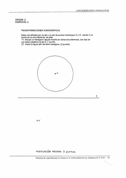
© Copyright 2026