
ATV71HD15M3X
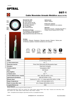
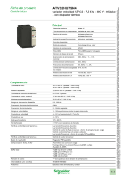
ATV71HD15M3X
Carácterísticas
variador de velocidad ATV71 - 15 kW 20 HP - 240 V
Principal
Gama de producto
Altivar 71
Tipo de producto o componente Variador de velocidad
Aplicación específica de producto Máquinas complejas, de alta potencia
Nombre de componente
ATV71
Potencia del motor en kW
15 kW en 200...240 V 3 fases
Potencia del motor en HP
20 hp en 200...240 V 3 fases
Longitud cable de motor
[Us] tensión de alimentación
nominal
200...240 V (- 15...10 %)
Número de fases de la red
3 fases
Corriente de línea
61.6 A para 240 V 3 fases 15 kW / 20 hp
71.7 A para 200 V 3 fases 15 kW / 20 hp
Filtro CEM
Sin filtro CEM
Estilo de conjunto
Con disipación de calor
Potencia aparente
25.6 kVA en 240 V 3 fases 15 kW / 20 hp
Corriente de cortocircuito de la
red
<= 22 kA, 3 fases
Corriente de salida nominal
66 A en 4 kHz 230 V 3 fases 15 kW / 20 hp
Máxima corriente transitoria
109 A para 2 s 3 fases 15 kW / 20 hp
99 A para 60 s 3 fases 15 kW / 20 hp
Frecuencia de salida
0.1...599 kHz
Frecuencia de conmutación
nominal
4 kHz
Frecuencia de conmutación
1...16 kHz regulable
4...16 kHz con factor de desclasificación de la
capacidad
Perfil de control de motor
asíncrono
Sistema ENA (adaptación de energía) para
cargas desequilibradas
Control vector flujo (FVC) con sensores (vector
actual)
Control vector flujo sin sensores (SFVC) (tensión
o vector actual)
Ley tensión/frecuencia (2 o 5 puntos)
Tipo de polarización
Sin impedancia para Modbus
Complementario
Destino del produc
Motores asíncronos
Motores síncronos
Límites tensión alimentación
170...264 V
Frecuencia de alimentación
50...60 Hz (- 5...5 %)
Frecuencia de red
47,5...63 Hz
Rango de velocidades
1...100 para motor asíncrono en modo de bucle abierto, sin respuesta rápida
1...50 para motor síncrono en modo de bucle abierto, sin respuesta rápida
1...1000 para motor asíncrono modo bucle cerrado con respuesta de codificador
Precisión de velocidad
+/- 0,01% de veloc. nominal para 0,2 Tn a Tn variación de par modo bucle cerrado
con respuesta de codificador
+/-10% de deslizamiento nomin para 0,2 Tn a Tn variación de par sin respuesta de
velocidad
Precisión de par
+/- 15 % en modo de bucle abierto, sin respuesta rápida
+/- 5 % modo bucle cerrado con respuesta de codificador
Sobrepar transitorio
220 % de par motor nominal +/- 10 % para 2 s
170 % de par motor nominal +/- 10 % para 60 s every 10 minutes
Par de frenado
<= 150 % con resistencia o resistencia de elevación
30 % sin resistencia de frenado
Perfil de control de motor síncrono
Contr.vec. sin respuesta veloc
1 / 10
La información incluída en esta documentación contiene descripciones generales y/o características técnicas de los productos. Esta documentación no pretende sustituir ni ser utilizada como herramienta garantizada de creación de especificaciones específicicas para usuarios finales. Es
responsabilidad del usuario final o integrador de realizar un apropiado análisis de riesgos, evaluación y testeo de los productos con respecto una aplicación específica. Schneider Electric Industries SAS o cualquiera de sus empresas subsidiarias o comercializadoras no se hacen responsables
de una posible mala interpretación o uso de la documentación incluída en este documento
Ficha de producto
Bucle de regulación
Regulador PI ajustable
Compensación desliz. motor
Regulable
Automático sea cual sea la carga
No disponible en ley tensión/frecuencia (2 ó 5 puntos)
Suprimible
Señalizaciones en local
1 LED rojo presencia de tensión unidad
Tensión de salida
<= de la potencia de la tensión de alimentación
Aislamien
Eléctrico entre alimentación y control
Tipo de cable
Con un kit NEMA Tipo 1 : 3-ramal cable UG 508 en 40 °C, cobre 75 °C PVC
Con un kit IP21 o IP31 : 3-ramal cable IEC en 40 °C, cobre 70 °C PVC
Sin juego de montaje : 1-ramal cable IEC en 45 °C, cobre 70 °C PVC
Sin juego de montaje : 1-ramal cable IEC en 45 °C, cobre 90 °C XLPE/EPR
Consecutivo, seguido, continuo, adosado
AI1-/AI1+, AI2, AO1, R1A, R1B, R1C, R2A, R2B, LI1...LI6, PWR Términal 2,5 mm² /
AWG 14
L1/R, L2/S, L3/T, U/T1, V/T2, W/T3, PC/-, PO, PA/+, PA, PB Términal 35 mm² / AWG 2
Par de apriete
AI1-/AI1+, AI2, AO1, R1A, R1B, R1C, R2A, R2B, LI1...LI6, PWR 0.6 N.m
L1/R, L2/S, L3/T, U/T1, V/T2, W/T3, PC/-, PO, PA/+, PA, PB 5.4 N.m / 47,7 lb.in
Suministro
Alimentación interna para potenciómetro de referencia (1-10 kOhmios), 10.5 V CC
+/- 5 %, <= 10 mA para protección de sobrecarga y cortocircuito
Aliment. interna, 24 V CC, límites de tensión 21...27 V, <= 200 mA para protección de
sobrecarga y cortocircuito
Número de entrada analógica
2
Tipo de entrada análogica
AI1-/Al1+ tensión diferencial bipolar +/- 10 V CC, tensión de entrada 24 V máx.,
resolución 11 bits + signo
AI2 corriente configurable por software 0...20 mA, impedancia 242 Ohm, resolución
11 bits
AI2 tensión configurable por software 0...10 V CC, tensión de entrada 24 V máx.,
impedancia 30000 Ohm, resolución 11 bits
Duración de muestreo
AI1-/Al1+ 2 ms, +/- 0,5 ms para analógica entradas
Al2 2 ms, +/- 0,5 ms para analógica entradas
LI1...LI5 2 ms, +/- 0,5 ms para discreta entradas
LI6 (si configurado como entrada lógica) 2 ms, +/- 0,5 ms para discreta entradas
Tiempo respuesta
<= 100 ms en STO (torque de seguridad fuera)
AO1 2 ms, tolerancia +/- 0,5 ms para analógica salidas
R1A, R1B, R1C 7 ms, tolerancia +/- 0,5 ms para discreta salidas
R2A, R2B 7 ms, tolerancia +/- 0,5 ms para discreta salidas
Precisión
AI1-/Al1+ +/- 2 % para variación temperatura 60 °C
AI2 +/- 2 % para variación temperatura 60 °C
AO1 +/- 1 ° para variación temperatura 60 °C
Error lineal
AI1-/Al1+, AI2 +/-0,15% del valor máximo
AO1 +/-0.2 %
Número de salida analógica
1
Tipo de salida análogica
AO1 corriente configurable por software 0...20 mA, impedancia 500 Ohm, resolución
10 bits
AO1 salida lógica configurable por sw 10 V <= 20 mA
AO1 tensión configurable por software 0...10 V CC, impedancia 470 Ohm, resolución
10 bits
Número de salida digital
2
Salida discreta
R1A, R1B, R1C lógica relé configurable NA/NC, durabilidad eléctrica 100000 ciclos
R2A, R2B lógica relé configurable NA, durabilidad eléctrica 100000 ciclos
Corriente de conmutación mínima
Lógica relé configurable 3 mA en 24 V CC
Intensidad de conmutación máxima
R1, R2 sobre resistivo carg, 5 A en 250 V CA, cos phi = 1,
R1, R2 sobre resistivo carg, 5 A en 30 V CC, cos phi = 1,
R1, R2 sobre inductivo carg, 2 A en 250 V CA, cos phi = 0,4,
R1, R2 sobre inductivo carg, 2 A en 30 V CC, cos phi = 0,4,
Número de entrada digital
7
Entrada discreta
LI6 : switch configurable 24 V CC con PLC niv 1, impedancia: 3500 Ohm
PWR : entrada seguridad 24 V CC, impedancia: 1500 Ohm de acuerdo con ISO
13849-1 nivel d
LI1...LI5 : programable 24 V CC con PLC niv 1, impedancia: 3500 Ohm
LI6 : sonda PTC configur. por conm. 0...6, impedancia: 1500 Ohm
Entrada lógica
LI1...LI5 lógica positiva (source), < 5 V (estado 0), > 11 V (estado 0)
LI1...LI5 lógica negativa (sink), > 16 V (estado 0), < 10 V (estado 0)
LI6 (si configurado como entrada lógica) lógica positiva (source), < 5 V (estado 0), >
11 V (estado 0)
LI6 (si configurado como entrada lógica) lógica negativa (sink), > 16 V (estado 0), <
10 V (estado 0)
Rampas de aceleración y deceleración
Adapt. auto de rampa en caso de superar capac. de desconex. a través de resistor
Acceleración ajustable por separado de 0,01 a 9000 s
2 / 10
S, U o personalizado
Frenado hasta parada
Mediante inyección de CC
Tipo de protección
Variador de velocidad contra superación veloc límit
Variador de velocidad contra pérdida fase de entrada
Variador de velocidad interrupc en circuito control
Variador de velocidad interrupc fase entrada
Variador de velocidad sobretensión en la línea de alimentación
Variador de velocidad Subtensión de la línea de alimentación
Variador de velocidad sobreintensidad entre fases de salida y tierra
Variador de velocidad protección contra sobrecalentamiento
Variador de velocidad sobretensiones en bus CC
Variador de velocidad cortocircuito entre fases del motor
Variador de velocidad protección térmica
Motor interrup fase motor
Motor Power Removal
Motor protección térmica
De la resistencia de aislamiento
> 1 mOhm en 500 V CC para 1 minuto a tierra
Resolución de frecuencia
Entrada analóg. 0,024/50 Hz
Unidad visualización 0.1 Hz
Protocolo del puerto de comunicación
CANopen
Modbus
Tipo de conector
1 RJ45 para Modbus en cara frontal
1 RJ45 para Modbus en terminal
SUB-D 9 macho en RJ45 para CANopen
Interfaz física
RS 485 de dos hilos para Modbus
Marco de transmisión
RTU para Modbus
Velocidad de transmisión
20 kbps, 50 kbps, 125 kbps, 250 kbps, 500 kbps, 1 Mbps para CANopen
4800 bps, 9600 bps, 19200 bps, 38,4 Kbps para Modbus en terminal
9600 bps, 19200 bps para Modbus en cara frontal
Formato de los datos
8 bits,1 stop, paridad impar para Modbus en cara frontal
8 bits, par impar o paridad no configurable para Modbus en terminal
Número de direcciones
1...247 para Modbus
1...127 para CANopen
Método de acceso
Esclavo para CANopen
Marca
CE
Posición de funcionamiento
Vertical +/- 10 grados
Altura
400 mm
Profundidad
213 mm
Anchura
230 mm
Peso del producto
22 kg
Tarjeta opcional
CC-Link tarjeta de comunicación
Tarjeta programable en el interior del controlador
DeviceNet tarjeta de comunicación
Ethernet/IP tarjeta de comunicación
Fipio tarjeta de comunicación
Tarjeta extensión E/S
Interbus-S tarjeta de comunicación
Tarjeta de interfaz para o codificador
Modbus Plus tarjeta de comunicación
Modbus TCP tarjeta de comunicación
Modbus/Uni-Telway tarjeta de comunicación
Tarjeta grúa aérea
Profibus DP tarjeta de comunicación
Profibus DP V1 tarjeta de comunicación
Medioambiente
nivel de ruido
60.2 dB de acuerdo con 86/188/EEC
fuerza dialéctrica
2830 V CC entre tierra y terminales de potencia
4230 V CC entre control y terminales de potencia
compatibilidad electromagnética
Prueba de inmunidad de radio frecuencia conducida de acuerdo con IEC 61000-4-6
nivel_3
Prueba de inmunidad oscilatoria/ráfagas eléctrica de acuerdo con IEC 61000-4-4
nivel_4
Prueba de inmunidad de descarga electroestática de acuerdo con IEC 61000-4-2
nivel_3
Prueba de inmunidad de la radiofrecuencia radiada del campo electromagnético de
acuerdo con IEC 61000-4-3 nivel_3
Prueba de inmunidad de huecos y caídas de tensión de acuerdo con IEC 61000-4-
3 / 10
11
Prueba de inmunidad de pico de tensión 1,2/50 μs - 8/20 μs de acuerdo con IEC
61000-4-5 nivel_3
normas
IEC 60721-3-3 clase 3C1
IEC 60721-3-3 clase 3S2
UL tipo 1
certificaciones
CSA
C-Tick
GOST
NOM 117
UL
grado de contaminación
2 de acuerdo con EN/IEC 61800-5-1
grado de protección IP
IP20 sobre la parte superior sin placa de obturación en cubierta de acuerdo con
EN/IEC 60529
IP20 sobre la parte superior sin placa de obturación en cubierta de acuerdo con
EN/IEC 61800-5-1
IP21 de acuerdo con EN/IEC 60529
IP21 de acuerdo con EN/IEC 61800-5-1
IP41 sobre la parte superior de acuerdo con EN/IEC 60529
IP41 sobre la parte superior de acuerdo con EN/IEC 61800-5-1
IP54 en parte inferior de acuerdo con EN/IEC 60529
IP54 en parte inferior de acuerdo con EN/IEC 61800-5-1
resistencia a las vibraciones
1,5 mm pico a pico (f = 3...13 Hz) de acuerdo con EN/IEC 60068-2-6
1 gn (f = 13...200 Hz) de acuerdo con EN/IEC 60068-2-6
resistencia a los choques
15 gn para 11 ms de acuerdo con EN/IEC 60068-2-27
humedad relativa
5...95 % sin condensación de acuerdo con IEC 60068-2-3
5...95 % sin goteo de agua de acuerdo con IEC 60068-2-3
temperatura ambiente de funcionamiento
-10...50 °C sin reducir la capacidad normal
temperatura ambiente de almacenamiento
-25...70 °C
altitud máxima de funcionamiento
<= 1000 m sin reducir la capacidad normal
1000...3000 m con desclasificación de corriente del 1% por 100 m
UL Type 1/IP 20 Drives
Dimensions without Option Card
Dimensions in mm
a
b
c
G
230 400 213
H
K
210 386
Ø
8
6
Dimensions in in.
a
9.05
b
15.75
c
G
8.38
8.26
H
15.20
K
0.31
Ø
0.23
Dimensions with 1 Option Card (1)
Dimensions in mm
4 / 10
a
c1
230 236
G
H
210 386
K
8
Ø
6
Dimensions in in.
a
c1
9.05 9.29
G
H
K
Ø
8.26 15.20 0.31 0.23
(1) Option cards: I/O extension cards, communication cards or "Controller Inside” programmable card.
Dimensions with 2 Option Cards (1)
Dimensions in mm
a
c2
230 259
G
H
210 386
K
8
Ø
6
Dimensions in in.
a
c2
G
H
K
Ø
9.05 10.20 8.26 15.20 0.31 0.23
(1) Option cards: I/O extension cards, communication cards or "Controller Inside” programmable card.
Mounting Recommendations
Depending on the conditions in which the drive is to be used, its installation will require certain precautions and the use of appropriate
accessories.
Install the unit vertically:
●
●
Avoid placing it close to heating elements
Leave sufficient free space to ensure that the air required for cooling purposes can circulate from the bottom to the top of the
unit.
Clearance
Mounting Types
Type A Mounting
Type B Mounting
5 / 10
Type C Mounting
By removing the protective blanking cover from the top of the drive, the degree of protection for the drive becomes IP 20.
The protective blanking cover may vary according to the drive model (refer to the user guide).
The protective blanking cover must be removed from ATV 71P•••N4Z drives when they are mounted in a dust and damp proof enclosure.
Specific Recommendations for Mounting the Drive in an Enclosure
Ventilation
To ensure proper air circulation in the drive:
●
●
Fit ventilation grilles.
Ensure that there is sufficient ventilation. If there is not, install a forced ventilation unit with a filter. The openings and/or fans
must provide a flow rate at least equal to that of the drive fans (refer to the product characteristics).
●
Use special filters with IP 54 protection.
●
Remove the blanking cover from the top of the drive.
Dust and Damp Proof Metal Enclosure (IP 54)
The drive must be mounted in a dust and damp proof enclosure in certain environmental conditions: dust, corrosive gases, high humidity
with risk of condensation and dripping water, splashing liquid, etc.
This enables the drive to be used in an enclosure where the maximum internal temperature reaches 50°C.
Wiring Diagram Conforming to Standards EN 954-1 Category 1, IEC/EN 61508 Capacity SIL1, in
Stopping Category 0 According to IEC/EN 60204-1
Three-Phase Power Supply with Upstream Breaking via Contactor
A1
ATV71 drive
6 / 10
KM1 Contactor
L1
DC choke
Q1 Circuit-breaker
Q2 GV2 L rated at twice the nominal primary current of T1
Q3 GB2CB05
S1, XB4 B or XB5 A pushbuttons
S2
T1
100 VA transformer 220 V secondary
(1)
Line choke (three-phase); mandatory for ATV71HC11Y…HC63Y drives (except when a special transformer is used (12-pulse)).
(2)
For ATV71HC40N4 drives combined with a 400 kW motor, ATV71HC50N4 and ATV71HC40Y…HC63Y, refer to the power terminal
connections diagram.
(3)
Fault relay contacts. Used for remote signalling of the drive status.
(4)
Connection of the common for the logic inputs depends on the positioning of the SW1 switch. The above diagram shows the
internal power supply switched to the “source” position (for other connection types, refer to the user guide).
(5)
There is no PO terminal on ATV71HC11Y…HC63Y drives.
(6)
Optional DC choke for ATV71H•••M3, ATV71HD11M3X…HD45M3X, ATV71•075N4…•D75N4 and ATV71P•••N4Z drives.
Connected in place of the strap between the PO and PA/+ terminals. For ATV71HD55M3X, HD75M3X, ATV71HD90N4…HC50N4
drives, the choke is supplied with the drive; the customer is responsible for connecting it.
(7)
Software-configurable current (0…20 mA) or voltage (0…10 V) analog input.
(8)
Reference potentiometer.
All terminals are located at the bottom of the drive. Fit interference suppressors on all inductive circuits near the drive or connected on
the same circuit, such as relays, contactors, solenoid valves, fluorescent lighting, etc.
Wiring Diagram Conforming to Standards EN 954-1 Category 1, IEC/EN 61508 Capacity SIL1, in
Stopping Category 0 According to IEC/EN 60204-1
Three-Phase Power Supply with Downstream Breaking via Switch Disconnector
A1
ATV71 drive
L1
DC choke
Q1 Circuit-breaker
Q2 Switch disconnector (Vario)
(1)
Line choke (three-phase), mandatory for ATV71HC11Y…HC63Y drives (except when a special transformer is used (12-pulse)).
(2)
For ATV71HC40N4 drives combined with a 400 kW motor, ATV71HC50N4 and ATV71HC40Y…HC63Y, refer to the power terminal
connections diagram.
(3)
Fault relay contacts. Used for remote signalling of the drive status.
(4)
Connection of the common for the logic inputs depends on the positioning of the SW1 switch. The above diagram shows the
internal power supply switched to the “source” position (for other connection types, refer to the user guide).
(5)
There is no PO terminal on ATV71HC11Y…HC63Y drives.
(6)
Optional DC choke for ATV71H•••M3, ATV71HD11M3X…HD45M3X, ATV71•075N4…•D75N4 and ATV71P•••N4Z drives.
Connected in place of the strap between the PO and PA/+ terminals. For ATV71HD55M3X, HD75M3X, ATV71HD90N4…HC50N4
drives, the choke is supplied with the drive; the customer is responsible for connecting it.
(7)
Software-configurable current (0…20 mA) or voltage (0…10 V) analog input.
(8)
Reference potentiometer.
7 / 10
All terminals are located at the bottom of the drive. Fit interference suppressors on all inductive circuits near the drive or connected on
the same circuit, such as relays, contactors, solenoid valves, fluorescent lighting, etc.
Wiring Diagram Conforming to Standards EN 954-1 Category 3, IEC/EN 61508 Capacity SIL2, in
Stopping Category 0 According to IEC/EN 60204-1
Three-Phase Power Supply, Low Inertia Machine, Vertical Movement
A1
ATV71 drive
A2
Preventa XPS AC safety module for monitoring emergency stops and switches. One safety module can manage the “Power
Removal” function for several drives on the same machine. In this case, each drive must connect its PWR terminal to its + 24 V via
the safety contacts on the XPS AC module. These contacts are independent for each drive.
F1
Fuse
L1
DC choke
Q1 Circuit-breaker
S1
Emergency stop button with 2 contacts
S2
XB4 B or XB5 A pushbutton
(1)
Power supply: 24 Vdc or Vac, 48 Vac, 115 Vac, 230 Vac.
(2)
S2: resets XPS AC module on power-up or after an emergency stop. ESC can be used to set external starting conditions.
(3)
Requests freewheel stopping of the movement and activates the “Power Removal” safety function.
(4)
Line choke (three-phase), mandatory for and ATV71HC11Y…HC63Y drives (except when a special transformer is used (12-pulse)).
(5)
The logic output can be used to signal that the machine is in a safe stop state.
(6)
For ATV71HC40N4 drives combined with a 400 kW motor, ATV71HC50N4 and ATV71HC40Y…HC63Y, refer to the power terminal
connections diagram.
(7)
Fault relay contacts. Used for remote signalling of the drive status.
(8)
Connection of the common for the logic inputs depends on the positioning of the SW1 switch. The above diagram shows the
internal power supply switched to the “source” position (for other connection types, refer to the user guide).
(9)
Standardized coaxial cable, type RG174/U according to MIL-C17 or KX3B according to NF C 93-550, external diameter
2.54 mm /0.09 in., maximum length 15 m / 49.21 ft. The cable shielding must be earthed.
(10) There is no PO terminal on ATV71HC11Y…HC63Y drives.
(11) Optional DC choke for ATV71H•••M3, ATV71HD11M3X…HD45M3X, ATV71•075N4…•D75N4 and ATV71P•••N4Z drives.
Connected in place of the strap between the PO and PA/+ terminals. For ATV71HD55M3X, HD75M3X, ATV71HD90N4…HC50N4
drives, the choke is supplied with the drive; the customer is responsible for connecting it.
(12) Software-configurable current (0…20 mA) or voltage (0…10 V) analog input.
(13) Reference potentiometer.
All terminals are located at the bottom of the drive. Fit interference suppressors on all inductive circuits near the drive or connected on
the same circuit, such as relays, contactors, solenoid valves, fluorescent lighting, etc.
Wiring Diagram Conforming to Standards EN 954-1 Category 3, IEC/EN 61508 Capacity SIL2, in
Stopping Category 1 According to IEC/EN 60204-1
Three-Phase Power Supply, High Inertia Machine
8 / 10
A1
ATV71 drive
A2
(5)
Preventa XPS ATE safety module for monitoring emergency stops and switches. One safety module can manage the "Power
Removal” safety function for several drives on the same machine. In this case the time delay must be adjusted on the drive
controlling the motor that requires the longest stopping time. In addition, each drive must connect its PWR terminal to its + 24 V
via the safety contacts on the XPS ATE module. These contacts are independent for each drive.
F1
Fuse
L1
DC choke
Q1 Circuit-breaker
S1
Emergency stop button with 2 N/C contacts
S2
Run button
(1)
Power supply: 24 Vdc or Vac, 115 Vac, 230 Vac.
(2)
Requests controlled stopping of the movement and activates the “Power Removal” safety function.
(3)
Line choke (three-phase), mandatory for ATV71HC11Y…HC63Y drives (except when a special transformer is used (12-pulse)).
(4)
S2: resets XPS ATE module on power-up or after an emergency stop. ESC can be used to set external starting conditions.
(5)
For stopping times requiring more than 30 seconds in category 1, use a Preventa XPS AV safety module which can provide a
maximum time delay of 300 seconds.
(6)
The logic output can be used to signal that the machine is in a safe state.
(7)
For ATV71HC40N4 drives combined with a 400 kW motor, ATV71HC50N4 and ATV71HC40Y…HC63Y, refer to the power terminal
connections diagram.
(8)
Fault relay contacts. Used for remote signalling of the drive status.
(9)
Connection of the common for the logic inputs depends on the positioning of the SW1 switch. The above diagram shows the
internal power supply switched to the “source” position (for other connection types, refer to the user guide).
(10) Standardized coaxial cable, type RG174/U according to MIL-C17 or KX3B according to NF C 93-550, external diameter
2.54 mm/0.09 in., maximum length 15 m/49.21 ft. The cable shielding must be earthed.
(11) Logic inputs LI1 and LI2 must be assigned to the direction of rotation: LI1 in the forward direction and LI2 in the reverse direction.
(12) There is no PO terminal on ATV71HC11Y…HC63Y drives.
(13) Optional DC choke for ATV71H•••M3, ATV71HD11M3X…HD45M3X, ATV71•075N4…•D75N4 and ATV71P•••N4Z drives.
Connected in place of the strap between the PO and PA/+ terminals. For ATV71HD55M3X, HD75M3X, ATV71HD90N4…HC50N4
drives, the choke is supplied with the drive; the customer is responsible for connecting it.
(14) Software-configurable current (0…20 mA) or voltage (0…10 V) analog input.
(15) Reference potentiometer.
All terminals are located at the bottom of the drive. Fit interference suppressors on all inductive circuits near the drive or connected on
the same circuit, such as relays, contactors, solenoid valves, fluorescent lighting, etc.
Derating Curves
The derating curves for the drive nominal current (In) depend on the temperature, the switching frequency and the mounting type. For
intermediate temperatures (e.g. 55°C), interpolate between 2 curves.
9 / 10
X
Switching frequency
(1)
Mounting type
10 /
10

© Copyright 2026