
Catálogo 2016 LED v2 (13/10/16) - (download)
1
General Catalogue
Catálogo General
2016
“This catalogue replaces the previous ones.
Data into this catalogue are subject to change
without prior notice for the purpose of improvement or
discontinued products. We kindly request you to ask
VJG NCVGUV URGEKſECVKQPU CPF EJGEM VJG EQPVGPVU YJGP
placing an order.
;QWECPſPFCPWRFCVGFXGTUKQPQHQWTECVCNQIWGCVQWT
website”.
www.elt.es
“El presente catálogo anula y sustituye los anteriores.
Los datos de este catálogo están sujeto a cambios
sin previo aviso por cuestiones de mejora o de
descatalogación de producto. Les rogamos se aseguren
de utilizar la documentación más actualizada y revisar
sus contenidos en el momento de realizar pedidos.
En nuestra página Web puede encontrar una versión
actualizada de nuestros productos”
www.elt.es
GENERAL INDEX
ÍNDICE GENERAL
eBLUE enabled devices
Dispositivos con tecnología eBLUE
7
Control gears and LED modules/strips
Equipos de alimentación y módulos/tiras LED
19
Accessories
Accesorios
119
GENERAL INFORMATION
Additional information for all ranges
INFORMACIÓN GENERAL
Información complementaria de todas las gamas
179
Guarantee
Garantía
189
Packaging
Empaquetado
191
Sales network
Red comercial
199
Product index
Índice de producto
203
Introduction
Introducción
ELT – Especialidades Luminotécnicas S.A.U. is a
Spanish company placed in Zaragoza which offers design,
manufacturing and commercialization of power supplies and
wireless solutions for lighting management within lighting
professional industry and street lighting.
ELT - Especialidades Luminotécnicas S.A.U. es una
empresa española con sede en Zaragoza que ofrece diseño,
fabricación y comercialización de equipos de alimentación y
soluciones inalámbricas para la gestión de la iluminación en el
sector profesional de la iluminación y el alumbrado.
Strongly focused on internationalization, ELT offers
technical solutions to more than a hundred countries, owning
a commercial office in Czech Republic and logistic facilities in
Lyon, where ELT FRANCE and ELT ITALY subsidiaries are
attended from.
Con un marcado enfoque a la internacionalización, ELT
ofrece soluciones a más de 100 países, contando con una
oficina comercial en República Checa y un almacén logístico en
Lyon, desde donde se atiende a las filiales ELT FRANCE y ELT
ITALIA.
Aer more than 40-year experience in lighting industry,
ELT keeps on investing in innovation and development in
order to offer efficient solutions providing maximum comfort in
lighting environments.
Tras más de 40 años de experiencia en el sector, ELT
sigue realizando una fuerte apuesta por la innovación y el
desarrollo para ofrecer soluciones eficientes que proporcionen
el máximo confort en materia de iluminación.
As a consequence, R&D facilities have been enlarged and a
new development division has been founded: Smart Systems.
These novelties allow ELT to keep on creating its own added
value and securing its competitiveness.
Fruto de lo anterior, se han ampliado las instalaciones
dedicadas a I+D y se ha creado una nueva división de desarrollo:
Sistemas Inteligentes. Todo esto permite a ELT seguir
creando valor añadido propio y afianzar su competitividad.
Its portfolio, very well-known and recognized in Africa,
America, Europe and Middle East Asia consists of the following
product ranges:
~ Wireless solutions for indoor and outdoor lighting control.
~ LED constant current drivers and modules.
~ LED constant voltage drivers and strips.
~ Electronic and conventional ballasts for fluorescent and HID
lamps (HPS, MH and MV).
~ Electronic and conventional transformers for halogen
lamps.
Su porfolio, muy reconocido en África, América, Europa y
Oriente Medio, está formado por las siguientes familias:
~ Soluciones inalámbricas para el control de la iluminación
interior y exterior.
~ Fuentes de alimentación y módulos LED de corriente constante.
~ Fuentes de alimentación y tiras LED de tensión constante.
~ Balastos electrónicos y reactancias electromagnéticas para
lámparas fluorescentes y de alta intensidad de descarga
(VSAP, HM y VM).
~ Transformadores electrónicos y electromagnéticos para
lámparas halógenas.
Purposing to improve customer service, and following other
editions policy, 2016 General Catalogue has been divided in
two volumes: one for eBLUE and LED technology and other for
FLUO, HID and HALO.
Con el objetivo de mejorar el servicio a los clientes, y al igual
que en ediciones anteriores, el catálogo general 2016 se encuentra dividido en dos tomos: uno para tecnología eBLUE y
LED y otro para FLUO, HID y HALO.
The LED catalogue brings together all up-to-now available
ELT solutions and includes the following novelties:
~ eBLUE Technology. DLCM-E-BT Drivers. Bluetooth
dimmable drivers for constant current LED modules.
~ eLED Modules. Street Lighting ranges and new models for
indoor lighting applications.
~ iLC Drivers. Programmable drivers for constant current LED
modules up to 75W, IP20 for Street Lighting applications.
~ DLCM Drivers. DALI dimmable drivers for constant current
LED modules, including a dip-Switch for fixing up to 5
different currents.
~ DLC Driver. 1…10V dimmable driver for constant current
LED modules up to 400W, IP67.
~ Accesories. ITP and ODP protection equipment, also new
ranges of controllers and aluminium profiles for constant
voltage applications.
Este catálogo LED reúne todas las soluciones de ELT
disponibles hasta la fecha e incluye las siguientes novedades:
~ Tecnología eBLUE. Drivers DLCM-E-BT. Equipos Bluetooth
regulables para módulos LED de corriente constante.
~ Módulos eLED. Gama para alumbrado público y nuevos
modelos para aplicaciones de iluminación interior.
~ Drivers iLC. Equipos programables de alimentación de
corriente constante para módulos LED hasta 75W IP20 para
aplicaciones de alumbrado público.
~ Drivers DLCM. Equipos regulables DALI de corriente
constante para módulos LED. Incorpora microswitch para
fijar hasta 5 corrientes diferentes.
~ Driver DLC. Equipo regulable 1… 10V de alimentación de
corriente constante para módulos LED hasta 400W. IP67.
~ Accesorios. Equipos de protección ITP y ODP para equipos
de alumbrado público y una nueva gama de controladores
y perfiles de aluminio para aplicaciones de iluminación con
equipos de alimentación de tensión constante.
For further information about product development and
novelties see the following URL:
Para obtener más información sobre desarrollos de producto
y novedades consultar la siguiente URL:
http://www.elt.es/novedades/i-novedades.html.
http://www.elt.es/novedades/novedades.html.
The following charts for information search are included in
this catalogue:
~ Most suitable drivers for eLED LINE modules (Page 77).
~ Product packaging belonging to each product in catalogue
(Page 191).
~ Alphabetical order product index (Page 203).
www.elt.es
Este catálogo incorpora las siguientes tablas para facilitar la
búsqueda de información:
~ Fuentes de alimentación más adecuadas para los módulos
de la gama eLED LINE (Pág. 77).
~ Embalaje correspondiente a cada artículo del catálogo (Pág.
191).
~ Índice de artículos por orden alfabético (Pág. 203).
5
eBLUE INDEX
ÍNDICE eBLUE
Bluetooth dimmable constant current control gears
for LED modules up to 50W.
Protection class II and independent use. IP20
Equipos Bluetooth regulables de alimentación
de corriente constante para módulos de LED hasta 50W.
Clase II y uso independiente. IP20 ............................ 12
eBLUE ENABLED DEVICES
DISPOSITIVOS CON TECNOLOGÍA eBLUE
Bluetooth smart wireless control device for lighting
control gears
Dispositivo inteligente de control inalámbrico Bluetooth
para fuentes auxiliares de iluminación ........................ 9
eBLUE TECHNICAL INFORMATION
INFORMACIÓN TÉCNICA SOBRE eBLUE..13
Bluetooth smart wireless trailing edge dimmer
Regulador trailing edge inteligente de
control inalámbrico Bluetooth .................................... 10
Bluetooth dimmable constant current control gears
for LED modules up to 50W. IP20
Equipos Bluetooth regulables de alimentación
de corriente constante para módulos de LED
hasta 50W. IP20 ........................................................ 11
8
www.elt.es
Bluetooth smart wireless control device
for lighting control gears
Dispositivo inteligente de control inalámbrico
Bluetooth para fuentes auxiliares de iluminación
eBLUE
0-10V/DALI
220-240V
50Hz
Ø 3,5
42,4 49,5 56,5
35,8
Wireless control device for LED, FLUO, HID and halogen control
gears with 0-10V, 1-10V or DALI dimming interface. The control
QWVRWVECPDGEQPſIWTGFGKVJGTCUCPCNQI8
8QTFKIKVCN
stand-alone DALI control interface.
Model
Modelo
eBLUE 0-10V / DALI
Maximum
sink/source
current
Maximum
current
Voltage
range
Intensidad
máxima
Rango
de
tensión
Corriente
máxima
suministrada/
absorbida
Bus
voltage
Shorcut
current
Tensión
de bus
Corriente en
cortocircuito
Operating
frequencies
Temp. funcionamiento
Input
voltage
DALI output / salida
Operating temp.
0-10V output / salida
Temp. máx. envolvente
Dispositivo de control inalámbrico para fuentes auxiliares de
iluminación LED, FLUO, HID y halógenas con interfaz 0-10V, 1-10V
Q&#.+.CUCNKFCFGEQPVTQNRWGFGUGTEQPſIWTCFCVCPVQCPCNÎIKEC
0-10V (1-10V) como digital DALI stand-alone.
Max. temp. at tc point
22,3
Ref.
No.
Tensión
de
entrada
Vac
A
Vdc
mA
Vdc
mA
GHz
tc (°C)
ta (°C)
9953070
220-240
0,6
0-10
7
12
7
2,4… 2,483
70
-20… +50
Frecuencias de
funcionamiento
~ IP20 equipment.
~ For built-in use.
~ Very small size for easy luminaire installation.
~ No need for additional new wiring, controllers or external gateways.
~ Wirelessly controllable with a smart device (smartphone, tablet...).
~ Intuitive and visual app for smartphones / tablets. Available for free
on Apple Store / Google Play.
~ Forms automatically a fast and secure wireless mesh network with
other eBLUE devices (up to 127 units/network).
`%QPſIWTCDNGCPCNQI
8QTFKIKVCN
&#.+UVCPFCNQPGQWVRWV
Default control mode: DALI stand-alone.
~ Easily implemented RGB and Tunable White solutions.
~ Controllable switched mains output.
~ Use timers to turn on and off scene at predetermined times.
~ Dimming and scenes control through standard on/off wall switches
(SwS) and motion sensors.
~ Cloud service that enhances user experience.
`&GXKEGſTOYCTGECPDGWRFCVGFQXGTVJGCKT
~ Max. terminal section area 0,75-1,5 mm2.
~ Equipo IP20.
~ Equipo a incorporar.
~ Dimensiones muy reducidas para facilitar su instalación en
luminarias.
~ No se necesita ningún dispositivo de enlace externo ni cableado
adicional.
~ Controlable de forma inalámbrica a través de un dispositivo
inteligente (smartphone, tablet...).
~ Visual e intuitiva app para smartphones / tablets. Disponible
gratuitamente en Apple Store / Google Play.
~ Forma automáticamente una rápida y segura red inalámbrica de
malla con otras unidades eBLUE (hasta 127 unid./red).
`5CNKFCEQPſIWTCDNGCPCNÎIKEC
8QFKIKVCN
&#.+UVCPFCNQPG
Modo de control por defecto: DALI stand-alone.
~ Soluciones RGB y Tunable White de fácil implementación.
~ Control de la salida de red conmutable.
~ Permite una programación horaria de escenas.
~ Dimado y control de escenas mediante interruptores de pared on/
off (SwS) y detectores de presencia convencionales.
~ Servicio en la nube que mejora la experiencia del usuario.
`'NſTOYCTGFGNFKURQUKVKXQRWGFGUGTCEVWCNK\CFQGPHWPEKQPCOKGPVQ
de manera inalámbrica.
~ Sección máxima en clemas: 0,75-1,5 mm2.
Packaging and weight p. 191 and www.elt.es/productos/packaging_ELT.pdf
Instructions manual on www.elt.es/productos/inst_manual.html
Embalaje y peso pág. 191 y www.elt.es/productos/embalaje_ELT.pdf
Manual de instrucciones en www.elt.es/productos/manual_instrucciones.html
Recommended for DALI or 0-10V control gears
Recomendado para equipos DALI o 0-10V
CONTROL GEAR
LED
MODULES
1-10V
L
N
EXTERNAL RELAY
9
CONTROL GEAR
NL
L
N
eBLUE
L
N
LN
0-10V / DALI
NL
www.elt.es
eBLUE
L
N
LN
EN 55015 Interferences / Interferencias
EN 61000-3-2 Harmonics / Armónicos
EN 61000-3-3 EMC Emission / CEM
EN 61347-1 Safety (general)
Seguridad (general)
EN 61347-2-11 Particular requirements
Requisitos particulares
EN 61547 EMC Immunity / Inmunidad CEM
Recommended for 1-10V control gears
Recomendado para equipos 1-10V
LED
MODULES
Bluetooth smart wireless trailing edge dimmer
Regulador trailing edge inteligente de
control inalámbrico Bluetooth
19,7
Ø 3,5
39,4 40,4
19,7
14
18,15
18,15
36,3
eBLUE TRAILING EDGE is an eBLUE enabled high quality trailing
edge dimmer for dimmable mains voltage powered loads. It can be
installed behind a traditional wall switch, into the casing or the celling
connection of a luminaire.
eBLUE TRAILING EDGE es un dimmer de alta calidad que incorpora
la tecnología eBLUE, empleado para regular cargas dimables por
TGEQTVGſPCNFGHCUG2WGFGUGTKPUVCNCFQFGVT¶UFGNKPVGTTWRVQTFG
pared y en la conexión o el interior de una luminaria.
Ref.
No.
A
110 Vac
230 Vac
110 Vac
230 Vac
W
W
W
tc (°C)
ta (°C)
85-240
0,65
70
150
70
150
50
50
50
65
-20… +45
Tensión
de
entrada
Lámparas
halógenas de
alta tensión
Módulos LED AC
regulables
W
eBLUE TRAILING EDGE
9953071
W
Operating temp.
Temp. funcionamiento
Max. case temperature
Temp. máx. envolvente
Modelo
AC dimmable LED
modules
High quality dimmable
CFL bulbs
Bombillas CFL regulables
de alta calidad
Model
High voltage
halogen lamps
High quality dimmable
LED bulbs
Bombillas LED regulables
de alta calidad
Vac
Input
voltage
Intensidad máxima
Trailing edge dimmable
LED drivers
Drivers LED regulables por
TGEQTVGſPCNFGHCUG
Maximum power I Potencia máxima
Maximum current
eBLUE
TRAILING
EDGE
85-240V
50-60Hz
~ IP20 equipment.
~ Class II electrical protection.
~ For built-in use.
~ Very small size for easy luminaire installation.
~ No need for additional new wiring, controllers or external gateways.
~ Wirelessly controllable with a smart device (smartphone, tablet...).
~ Intuitive and visual app for smartphones / tablets. Available for free
on Apple Store / Google Play.
~ Forms automatically a fast and secure wireless mesh network with
other eBLUE devices (up to 127 units/network).
~ Used for high quality dimmable LED bulbs.
~ Used for high quality dimmable CFL bulbs.
~ Used for high voltage halogens.
~ Used for dimmable AC LED modules.
~ Used for trailing edge dimmable LED drivers.
~ Use timers to turn on and off scenes at predetermined times.
~ Dimming and scenes control through standard on/off wall switches
(SwS) and motion sensors.
~ Cloud service that enhances user experience.
`&GXKEGſTOYCTGECPDGWRFCVGFQXGTVJGCKT
~ Max. terminal section area 0,5-1,5 mm2.
~ Equipo IP20.
~ Protección eléctrica Clase II.
~ Equipo a incorporar.
~ Dimensiones muy reducidas para facilitar su instalación en
luminarias.
~ No se necesita ningún dispositivo de enlace externo ni cableado
adicional.
~ Controlable de forma inalámbrica a través de un dispositivo
inteligente (smartphone, tablet...).
~ Visual e intuitiva app para smartphones / tablets. Disponible
gratuitamente en Apple Store / Google Play.
~ Forma automáticamente una rápida y segura red inalámbrica de
malla con otras unidades eBLUE (hasta 127 unid./red).
~ Válido para bombillas LED regulables de alta calidad.
~ Válido para bombillas CFL regulables de alta calidad.
~ Válido para lámparas halógenas de alta tensión.
~ Válido para módulos LED AC regulables.
`8¶NKFQRCTCFTKXGTU.'&TGIWNCDNGURQTTGEQTVGſPCNFGHCUG
~ Permite una programación horaria de escenas.
~ Dimado y control de escenas mediante interruptores de pared on/
off (SwS) y detectores de presencia convencionales.
~ Servicio en la nube que mejora la experiencia del usuario.
`'NſTOYCTGFGNFKURQUKVKXQRWGFGUGTCEVWCNK\CFQGPHWPEKQPCOKGPVQ
de manera inalámbrica.
~ Sección máxima en clemas: 0,5-1,5 mm2.
Packaging and weight p. 191 and www.elt.es/productos/packaging_ELT.pdf
Instructions manual on www.elt.es/productos/inst_manual.html
Embalaje y peso pág. 191 y www.elt.es/productos/embalaje_ELT.pdf
Manual de instrucciones en www.elt.es/productos/manual_instrucciones.html
EN 55015 Interferences / Interferencias
EN 61000-6-2 EMC Inmunity for industrial environments
Inmunidad CEM en entornos industriales
EN 61547 EMC Immunity / Inmunidad CEM
EN-60669 Switches / Interruptores
EN 300 328 ERM wide band transmissions systems
Compatibilidad electromagnética y espectro radioeléctrico
EN 61058 Switches for appliances / Interruptores para aparatos
L
N
N
L
N
10
www.elt.es
Bluetooth dimmable constant current control gears
for LED modules up to 50W. IP20
Equipos Bluetooth regulables de alimentación
de corriente constante para módulos de LED
hasta 50W. IP20
DLCM-E-BT
220-240V
50-60Hz
29,5
Ø 4,2
69 63
92,5
Temp.
funcionamiento
Operating
temp.
Temp.máx.
envolvente
Max.temp.
at tc point
Frecuencias de
funcionamiento
Approvals
Homologaciones
mA
Operating
frequencies
Corrientes de salida
Rendimiento
del sistema
Ref.
No.
Modelo
System
GHſEKGPE[
Model
Output
voltage
range
Rango de
tensión de
salida
Factor de
potencia
Output currents
Power factor
108
Vdc
NJ
dž(%)
GHz
tc (°C)
ta (°C)
DLCM 50/250…350-E-BT
9918391
250
275
300
325
350
75… 143
0,98
89
2,4… 2,483
75
-20...+50
(*)
01
DLCM 50/400…500-E-BT
9918392
400
425
450
475
500
57… 100
0,97
88
2,4… 2,483
75
-20...+50
(*)
01
DLCM 50/600…700-E-BT
9918393
600
625
650
675
700
40… 72
0,97
87
2,4… 2,483
75
-20...+45
(*)
01
For other currents consult our commercial department / Para otras corrientes consultar con el departamento comercial
Packaging and weight p. 191 and www.elt.es/productos/packaging_ELT.pdf
Instructions manual on www.elt.es/productos/inst_manual.html
Embalaje y peso pág. 191 y www.elt.es/productos/embalaje_ELT.pdf
Manual de instrucciones en www.elt.es/productos/manual_instrucciones.html
1
100
PWM Output Dimming
OR
ORC < 5%
ON
1
EN-61347-2-13 Safety / Seguridad
EN-62384 Perfomance / Funcionamiento
EN-61000-3-2 Harmonics / Armónicos
EN-61000-3-3 EMC Emission / CEM
EN-55015 Interferences / Interferencias
EN-61547 EMC Immunity / Inmunidad CEM
www.elt.es
DLCM ...-E-BT
N
L
11
1 2 3 4
(1) Except 9918391
* In process
~ Equipo IP20.
~ Equipo a incorporar. Clase I.
~ Longitud máxima de los cables del secundario: 2 m.
~ 5 corrientes de salida seleccionables con microswitch.
~ No se necesita ningún dispositivo de enlace externo ni cableado
adicional.
~ Controlable de forma inalámbrica a través de un dispositivo
inteligente (smartphone, tablet…). App gratuita disponible en Apple
Store/Google Play.
~ Forma automáticamente una rápida y segura red inalámbrica de
malla con otras unidades eBLUE (hasta 127 unid./red).
~ Dimado y control de escenas mediante interruptores de pared on/
off (SwS) y detectores de presencia convencionales.
~ Servicio en la nube que mejora la experiencia de usuario.
`'NſTOYCTGFGNFKURQUKVKXQRWGFGUGTCEVWCNK\CFQGPHWPEKQPCOKGPVQ
de manera inalámbrica.
~ Rango de regulación de 3… 100%.
~ Regulación a la salida por PWM.
~ Rizado de corriente de salida (ORC) <5%.
~ Bajo consumo en stand-by: <0,8W.
~ Bajo factor de distorsión armónica (THD) a máxima carga: <10%.
~ Alto factor de potencia.
~ Protección térmica dinámica.
~ Protección contra cortocircuito, sobrecarga y circuito abierto.
~ Tensión permitida AC/DC: 198-264V.
`%QPGEVQTGUFGEQPGZKÎPT¶RKFCEQPOWGNNGFGſLCEKÎP
Sección conductor 0,5 - 1,5 mm2.
~ Vida útil a máxima ta permitida: 50.000h (tasa de fallo max. 0,2%
por 1000h).
(1) Excepto 9918391
* En proceso
ED
~ IP20 equipment.
~ Driver for built-in use. Class I.
~ Maximum length of secondary wires: 2 m.
~ 5 output selectable currents through dip-switch.
~ No need for additional new wiring, controllers or external gateways.
~ Wirelessly controllable with a smart device (smartphone, tablet…).
App available for free on Apple Store / Google Play.
~ Forms automatically a fast and secure wireless mesh network with
other eBLUE devices (up to 127 units/network).
~ Dimming and scenes control through standard on/off wall switches
(SwS) and motion sensors.
~ Cloud service that enhances user experience.
`&GXKEGſTOYCTGECPDGWRFCVGFQXGTVJGCKT
~ Regulation range 3...100%.
~ PWM output dimming.
~ Output ripple current (ORC) <5%.
~ Low stand-by power consumption <0,8W.
~ Low Total Harmonic Distortion (THD) at maximum power: <10%.
~ High power factor.
~ Dynamic thermal protection.
~ Protection against short circuit, overload and no load operation.
~ Permitted input voltage AC/DC: 198-264V.
`4CRKFEQPPGEVQTYKVJſZKPIURTKPI%QPFWEVQTUK\GOO2.
~ Nominal lifetime at max. ta allowed: 50.000h (with a failure rate
max. 0,2% per 1000h).
LED
MODULES
Bluetooth dimmable constant current control gears
for LED modules up to 50W.
Protection class II and independent use. IP20
Equipos Bluetooth regulables de alimentación
de corriente constante para módulos de LED hasta 50W.
Clase II y uso independiente. IP20
153,5
32
Ø4
70,2
Operating
temp.
Temp.
funcionamiento
Approvals
Homologaciones
mA
Max.temp.
at tc point
Temp.máx.
envolvente
Corrientes de salida
Frecuencias de
funcionamiento
Ref.
No.
Modelo
Operating
frequencies
Model
Output
voltage
range
Rango de
tensión de
salida
System
GHſEKGPE[
Output currents
Rendimiento
del sistema
2
160,5
170,5
Factor de
potencia
4,5
Power factor
Vdc
NJ
dž(%)
GHz
tc (°C)
ta (°C)
DLCM 50/250…350-E-C2-BT
9918401
250
275
300
325
350
75… 143
0,98
89
2,4… 2,483
75
-20...+50
(*)
01
DLCM 50/400…500-E-C2-BT
9918402
400
425
450
475
500
57… 100
0,97
88
2,4… 2,483
75
-20...+50
(*)
01
DLCM 50/600…700-E-C2-BT
9918403
600
625
650
675
700
40… 72
0,97
87
2,4… 2,483
75
-20...+45
(*)
01
For other currents consult our commercial department / Para otras corrientes consultar con el departamento comercial
~ IP20 equipment for independent use. Class II control gear.
~ Maximum length of secondary wires: 5 m.
~ 5 output selectable currents through dip-switch.
~ No need for additional new wiring, controllers or external gateways.
~ Wirelessly controllable with a smart device (smartphone, tablet…).
App available for free on Apple Store / Google Play.
~ Forms automatically a fast and secure wireless mesh network with
other eBLUE devices (up to 127 units/network).
~ Dimming and scenes control through standard on/off wall switches
(SwS) and motion sensors.
~ Cloud service that enhances user experience.
`&GXKEGſTOYCTGECPDGWRFCVGFQXGTVJGCKT
~ Regulation range 3...100%.
~ PWM output dimming.
~ Output ripple current (ORC) <5%.
~ Low stand-by power consumption <0,8W.
~ Low Total Harmonic Distortion (THD) at maximum power: <10%.
~ High power factor.
~ Dynamic thermal protection.
~ Protection against short circuit, overload and no load operation.
~ Permitted input voltage AC/DC: 198-264V.
`4CRKFEQPPGEVQTYKVJſZKPIURTKPI%QPFWEVQTUK\GOO2.
~ Nominal lifetime at max. ta allowed: 50.000h (with a failure rate
max. 0,2% per 1000h).
(1) Except 9918401
* In process
~ Equipo para uso independiente IP20. Equipo Clase II.
~ Longitud máxima de los cables del secundario: 5 m.
~ 5 corrientes de salida seleccionables con microswitch.
~ No se necesita ningún dispositivo de enlace externo ni cableado
adicional.
~ Controlable de forma inalámbrica a través de un dispositivo
inteligente (smartphone, tablet…). App gratuita disponible en Apple
Store/Google Play.
~ Forma automáticamente una rápida y segura red inalámbrica de
malla con otras unidades eBLUE (hasta 127 unid./red).
~ Dimado y control de escenas mediante interruptores de pared on/
off (SwS) y detectores de presencia convencionales.
~ Servicio en la nube que mejora la experiencia de usuario.
`'NſTOYCTGFGNFKURQUKVKXQRWGFGUGTCEVWCNK\CFQGPHWPEKQPCOKGPVQ
de manera inalámbrica.
~ Rango de regulación de 3… 100%.
~ Regulación a la salida por PWM.
~ Rizado de corriente de salida (ORC) <5%.
~ Bajo consumo en stand-by: <0,8W.
~ Bajo factor de distorsión armónica (THD) a máxima carga: <10%.
~ Alto factor de potencia.
~ Protección térmica dinámica.
~ Protección contra cortocircuito, sobrecarga y circuito abierto.
~ Tensión permitida AC/DC: 198-264V.
`%QPGEVQTGUFGEQPGZKÎPT¶RKFCEQPOWGNNGFGſLCEKÎP
Sección conductor 0,5 - 1,5 mm2.
~ Vida útil a máxima ta permitida: 50.000h (tasa de fallo max. 0,2%
por 1000h).
(1) Excepto 9918401
* En proceso
Packaging and weight p. 191 and www.elt.es/productos/packaging_ELT.pdf
Instructions manual on www.elt.es/productos/inst_manual.html
Embalaje y peso pág. 191 y www.elt.es/productos/embalaje_ELT.pdf
Manual de instrucciones en www.elt.es/productos/manual_instrucciones.html
PWM Output Dimming
100
ED
1
OR
ORC < 5%
ON
1
EN-61347-2-13 Safety / Seguridad
EN-62384 Perfomance / Funcionamiento
EN-61000-3-2 Harmonics / Armónicos
EN-61000-3-3 EMC Emission / CEM
EN-55015 Interferences / Interferencias
EN-61547 EMC Immunity / Inmunidad CEM
1 2 3 4
DLCM-EC2-BT
220-240V
50-60Hz
LED
MODULES
DLCM ...-E-C2-BT
N
L
12
www.elt.es
eBLUE technical information
Información técnica sobre eBLUE
Switch to Smart
Enabling eBLUE technology, you can control your lights
to create just the right mood or ambience. Dim your lights
and adjust their colour by using your existing wall switches,
motion sensors or on your smartphone or tablet. You get a
whole new lighting experience.
Con eBLUE podrás controlar la iluminación para crear el
ambiente deseado de una manera muy sencilla. Regula la
intensidad de tus luminarias y ajusta su color mediante los
interruptores de pared existentes, detectores de presencia o
a través de tu smartphone/tablet. Sin duda una nueva experiencia de iluminación.
Bluetooth 4.0
RANGE / ALCANCE *
- Indoor / Interiores max. 30m
- Outdoor / Exteriores max. 50m
* Each eBLUE also acts as a repeater (mesh network),
so longer ranges can be achieved by using multiple
eBLUE devices.
Range is highly dependent on the surrounding and
obstacles, such as walls and building materials.
Sync. via cloud
Sincronización en la nube
Old switches made smart
Dota de inteligencia a tus
interruptores convencionales
* Cada eBLUE actúa como un repetidor (red de malla).
De esta manera se pueden conseguir alcances
superiores instalando múltiples equipos eBLUE.
El alcance depende fuertemente del entorno y los
obstáculos situados en él, así como de muros y
materiales de construcción.
MAIN FEATURES / CARACTERÍSTICAS PRINCIPALES
Easy to install
Fácil de instalar
Practical daily use
Práctico uso diario
Delightful to use
Visual e intuitivo
Lighting as experience
Iluminación como experiencia
You don’t need any new wiring,
switches, devices or networks. Plug
KPVJGNKIJVKPIſZVWTGCPFRCKTKV
with your phone or tablet. No other
EQPſIWTCVKQPUPGGFGF
Sin necesidad de nuevos cableados,
interruptores, dispositivos o redes.
Conecta la luminaria y vincúlala
con tu smartphone o tablet. No
PGEGUKVCT¶UQVTCUEQPſIWTCEKQPGU
adicionales.
You can still use your existing wall
switches. They will have a new life:
use them as dimmers and control
many lamps with one switch.
Puedes seguir usando tus
interruptores convencionales.
Ahora tendrán una nueva vida:
úsalos como dimmers y controla
varias lámparas con un solo
interruptor.
You can control your lights with an
intuitive and visual user interface
on your smartphone or tablet.
Puedes controlar tus lámparas
a través de una visual e intuitiva
interfaz desde tu smartphone o
tablet.
eBLUE is more than just a
light switch. With a tap on your
smartphone you can set the
ambience for study, watching a
movie, or a romantic dinner.
eBLUE es más que un interruptor.
Con tan sólo un toque en tu
smartphone puedes seleccionar el
ambiente más adecuado para cada
ocasión.
www.elt.es
13
DOWNLOAD THE FREE APP
DESCARGA LA APP GRATUITA
Search `Casambi´ or just scan below QR code:
Busca `Casambi´ o simplemente escanea el siguiente código QR:
Compatible devices
Dispositivos compatibles:
iPhone 4S or later.
iPad 3 or later.
iPod Touch 5 th gen or later.
Android 4.4 KitKat or later devices produced after 2013 with
full BT 4.0 support.
iPhone 4S o posteriores.
iPad 3 o posteriores.
iPod Touch 5ª generación o posteriores.
Android 4.4 KitKat o dispositivos fabricados después del
2013 con soporte BT 4.0.
USER INTERFACE
INTERFAZ DE USUARIO
eBLUE is the easiest and most natural way
to control your lights:
eBLUE es la forma más sencilla y natural
de controlar tus lámparas:
With the app you can control all eBLUE enabled lighting
ſZVWTGU6JGſTUVVKOGWUGJCUDGGPOCFGGCU[CPFKPVWKVKXG
With one tap you are ready to control all your lights.
A través de la app podrás controlar todas las luminarias
habilitadas con la tecnología eBLUE. La puesta en marcha
se realiza de forma fácil e intuitiva. Simplemente con una
pulsación estarás preparado para controlar toda tu iluminación.
14
www.elt.es
Controlling all your lamps from one view:
Controla todas tus lámparas a través de la
misma interfaz:
9KVJVJGCRR[QWECPEQPVTQNCNN[QWTNKIJVKPIſZVWTGUYKVJ
one view. It is possible to control your lights individually or as
a group. For example you can create a group of your kitchen,
QHſEGQTUJQRNKIJVUCPFVWTPVJGOCNNQHHQPYKVJLWUVQPG
tap. Or you can dim the living room lights to pleasant light
level for a movie.
Con la app podrás controlar todas tus lámparas desde la
misma pantalla. Es posible controlarlas individualmente o
por grupos. Por ejemplo, puedes crear un grupo con las lámRCTCUFGVWEQEKPCQſEKPCQVKGPFC[GPEGPFGTCRCICTVQFCU
ellas con una única pulsación. También puedes regular las
N¶ORCTCUFGVWUCNÎPſLCPFQWPPKXGNFGNW\CITCFCDNGRCTC
ver una película.
Control your lights from a photo:
Controla tus lámparas desde una
fotografía:
The Gallery in app is the most natural way of controlling
your lights. Take a picture of your room(s) and place the lamp
EQPVTQNUQXGTVJGNKIJVKPIſZVWTGUKPVJGRKEVWTG0QY[QWECP
EQPVTQN[QWTNKIJVKPIſZVWTGUXKUWCNN[TKIJVHTQOVJGRKEVWTG
La Galería en la app es la forma más natural de controlar tu iluminación. Toma una fotografía de tu(s) estancia(s) y
coloca los controles de lámpara sobre ellas en la fotografía.
Ahora puedes controlar tus lámparas visualmente desde la
propia fotografía.
www.elt.es
15
Create scenes for different lighting
situations:
Crea escenas para distintas situaciones:
You can create different scenes for different occasions.
5GVVJGNKIJVULWUVTKIJVHQTFKPKPIQHſEGGPXKTQPOGPVUQTUJQR
promotions and save the settings in a scene. Now you can
change the lighting with one tap for different occasions for
example a party or a meeting with a customer.
Puedes crear varias escenas para diferentes ocasiones.
Establece la iluminación adecuada para una cena, entornos
FGQſEKPCQRTQOQEKQPGUFGWPCVKGPFC[IWCTFCNCEQPſIWración en una escena. Ahora puedes cambiar la iluminación
con una única pulsación para adecuarla a diferentes situaEKQPGURQTGLGORNQWPCſGUVCQWPCTGWPKÎPEQPWPENKGPVG
Share your network and allow other
devices to control your lights:
Comparte tu red y permite a otros
dispositivos controlar tus lámparas:
eBLUE has four different levels for sharing and access
control. You can decide if your network is open to everyone
or if other users need a password to access your network. If
you have several users and devices using the same network,
all changes made with one device will be automatically updated to the other devices with cloud service.
eBLUE tiene cuatro niveles diferentes para compartir y
controlar el acceso a tu red. Puedes decidir si tu red se encuentra abierta a todo el mundo o si se necesita una contraseña para acceder a ella. En caso de que varios usuarios/
dispositivos estén utilizando la misma red, todos los cambios
realizados por uno de ellos se actualizarán automáticamente
en los demás dispositivos a través del servidor en la nube.
16
www.elt.es
ADITTIONAL FEATURES
CARACTERÍSTICAS ADICIONALES
~ Cloud service that enhances user experience.
~ Servicio en la nube que mejora la experiencia de usuario.
~ &GXKEGUſTOYCTGECPDGWRFCVGFQXGTVJGCKT
`'NſTOYCTGFGNQUFKURQUKVKXQURWGFGUGTCEVWCNK\CFQGP
funcionamiento de manera inalámbrica.
~ Support for scene animations.
~ Support for Apple Watch.
~ Soporte para animaciones de escenas.
~ Support for remote gateway.
~ Support for iBeacon.
~ Soporte para Apple Watch.
~ Support for timmers allowing switching scenes ON or
OFF based on date, weekdays, hour/minute or sunrise/
sunset event switching.
~ Soporte para iBeacon.
~ Soporte para acceso remoto (gateway).
~ Soporte para programación horaria de escenas en función de una fecha concreta, días de la semana, una hora
determinada o en base al amanecer/atardecer.
DIMMING WITHOUT APP
REGULACIÓN SIN LA APP
1.- Turn lights on from wall switch.
1.- Enciende las lámparas desde el interruptor.
2.-/CMG C ƀKEM D[ SWKEMN[ VWTPKPI YCNN UYKVEJ QHH CPF QP
(max. 1sec.). The light level starts to increase gradually.
2.-*C\WPCRCICFQ[GPEGPFKFQT¶RKFQ
őƀKEMŒEQPGNKPterruptor (máx. 1 seg.). El nivel de luz empezará a aumentar gradualmente.
3.-/CMG CPQVJGT ƀKEM CV FGUKTGF FKO NGXGN 6JG UGNGEVGF
level is saved automatically.
3.-4GCNK\CQVTQCRCICFQ[GPEGPFKFQT¶RKFQ
őƀKEMŒGPGN
nivel de luz deseado. El nivel seleccionado se quedará
guardado automáticamente.
4.-+HVJGUGEQPFƀKEMKUPQVFQPGKPUGEVJGNKIJVKPVGPsity reaches its maximum level.
4.- Si el segundo apagado y encendido rápido no se ha
realizado en 15 seg., la intensidad de la luz alcanzará
su nivel máximo.
t
1
2
3
4
CUSTOMIZE YOUR PRODUCT
PERSONALIZA TU PRODUCTO
;QWECPETGCVG[QWTQYPſZVWTGRTQſNGUQPCFOKPYGDUKVG
CPFVJGPEQPſIWTGG$.7'FGXKEGUCEEQTFKPIVQVJGO
2WGFGU ETGCT VWU RTQRKQU RGTſNGU C VTCXÃU FG NC R¶IKPC
YGD FG CFOKPKUVTCFQT [ FGURWÃU EQPſIWTCT NCU WPKFCFGU
eBLUE de acuerdo a los mismos.
www.elt.es
17
G$.7' FGXKEGU CTG FGNKXGTGF YKVJ VJG UVCPFCTF EQPſIWTCVKQP +V KU RQUUKDNG VQ EJCPIG VJG EQPſIWTCVKQP CPF QVJGT
details with admin account.
.CUWPKFCFGUG$.7'UGGPVTGICPEQPNCEQPſIWTCEKÎPGUV¶PFCT'URQUKDNGECODKCTUWEQPſIWTCEKÎP[QVTQUFGVCNNGU
a través de la cuenta de administrador.
9KVJ VJG UVCPFCTF EQPſIWTCVKQP VJG CRR YKNN FKURNC[ VJG
UVCPFCTF KEQP CPF FGVCKNU DWV CHVGT EQPſIWTCVKQP [QWT
QYP ſZVWTG KEQP CPF FGVCKNU CTG UJQYP $[ ETGCVKPI [QWT
QYP ſZVWTG [QW ECP CNUQ CFLWUV G$.7' VQ YQTM YKVJ [QWT
product in the best way.
%QPNCEQPſIWTCEKÎPGUV¶PFCTNCCRROQUVTCT¶NQUKEQPQU
[FGVCNNGUGUV¶PFCTGURGTQVTCUNCEQPſIWTCEKÎPUGOQUVTCT¶PVWURTQRKQUKEQPQU[FGVCNNGUFGNRGTſNETGCFQ#VTCXÃU
FGNCETGCEKÎPFGVWURTQRKQURGTſNGURQFT¶UCLWUVCTNCWPKdad eBLUE, optimizándola para tu producto.
MORE INFORMATION
MÁS INFORMACIÓN
For downloading full information, please visit our website
Para descargar la información completa visita nuestra web
http://www.elt.es/productos/eblue_en.html
http://www.elt.es/productos/eblue_es.html
Switch to Smart
18
www.elt.es
LED INDEX
ÍNDICE LED
Constant multicurrent control gear for LED modules up to
42W. IP20
Equipo de alimentación multicorriente de corriente
constante para módulos de LED hasta 42W. IP20 ... 31
CONSTANT CURRENT CONTROL GEARS
EQUIPOS DE ALIMENTACIÓN DE
CORRIENTE CONSTANTE
Constant current control gears for LED modules
up to 11W. IP20
Equipos de alimentación de corriente constante para
módulos de LED hasta 11W. IP20 ............................ 22
Constant multicurrent control gear for LED modules up to
42W. Protection class II and independent use. IP20
Equipo de alimentación multicorriente de corriente
constante para módulos de LED hasta 42W. Clase II y
uso independiente. IP20 ........................................... 32
Constant current control gears for LED modules up to
25W. Universal voltage 110-277V. IP20
Equipos de alimentación de corriente constante para
módulos de LED hasta 25W.
Tensión universal 110-277V. IP20 ........................... 23
DALI dimmable constant current control gears for LED
modules up to 50W. IP20
Equipos DALI regulables de alimentación de corriente
constante para módulos de LED hasta 50W. IP20 ... 34
Dimmable constant current control gears for LED
modules up to 16 and 25W. IP20
Equipos regulables de alimentación de corriente
constante para módulos de LED hasta 16 y 25W.
IP20 .......................................................................... 24
DALI dimmable constant current control gears for LED
modules up to 50W. Protection class II and
independent use. IP20
Equipos DALI regulables de alimentación de corriente
constante para módulos de LED hasta 50W.
Clase II y uso independiente. IP20 ........................... 35
Constant current control gears for LED modules
up to 50W. IP20
Equipos de alimentación de corriente constante para
módulos de LED hasta 50W. IP20 ........................... 25
Constant current control gears for LED modules
up to 60W. IP20
Equipos de alimentación de corriente constante para
módulos de LED hasta 60W. IP20 ........................... 37
Constant current control gears for LED modules
up to 50W. Protection class II and independent use. IP20
Equipos de alimentación de corriente constante para
módulos de LED hasta 50W. Clase II y uso
independiente. IP20 ................................................. 26
Constant current control gears for LED modules
up to 90W. IP20
Equipos de alimentación de corriente constante para
módulos de LED hasta 90W. IP20 ........................... 38
Constant current control gears for LED modules up to
50W. Universal voltage 110-277V. IP20
Equipos de alimentación de corriente constante para
módulos de LED hasta 50W.
Tensión universal 110-277V. IP20 ........................... 27
Constant current control gears for LED modules up to
50W. Universal voltage 110-277V. IP20
Equipos de alimentación de corriente constante para
módulos de LED hasta 50W.
Tensión universal 110-277V. IP20 ........................... 39
Constant current control gears for LED modules up to
50W. Protection class II and independent use.
Universal voltage 110-277V. IP20
Equipos de alimentación de corriente constante
para módulos de LED hasta 50W. Clase II y uso
independiente. Tensión universal 110-277V. IP20 ... 28
DALI dimmable constant current control gears for LED
modules up to 90W. IP20
Equipos DALI regulables de alimentación de corriente
constante para módulos de LED hasta 90W.
IP20 ......................................................................... 40
1...10V Dimmable constant current control gears for LED
modules up to 42W. IP20
Equipos 1...10V regulables de alimentación de corriente
constante para módulos de LED hasta 42W. IP2 ..... 29
Constant current control gears for LED modules up to
10W. IP20
Equipos de alimentación de corriente constante para
módulos de LED hasta 10W. IP20 .......................... 42
1...10V Dimmable constant current control gears for LED
modules up to 42W. Protection class II and independent
use. IP20
Equipos 1...10V regulables de alimentación de corriente
constante para módulos de LED hasta 42W. Clase II y
uso independiente. IP20 ........................................... 30
Full PROGRAMMABLE constant current control gears
for LED modules up to 75W. IP20. Street lighting
applications
Equipo PROGRAMABLE de alimentación de corriente
constante para módulos LED hasta 75W. IP20.
Aplicaciones de alumbrado público .......................... 43
20
www.elt.es
Constant current control gears for LED modules up to
150W. IP20 Street lighting applications
Equipos de alimentación de corriente constante para
módulos de LED hasta 150W. IP20. Aplicaciones de
alumbrado público .................................................... 46
CONSTANT VOLTAGE CONTROL GEARS
EQUIPOS DE ALIMENTACIÓN DE TENSIÓN
CONSTANTE
Constant voltage control gears for LED up to 75W. IP20
Equipos de alimentación de tensión constante para LED
hasta 75W. IP20 ....................................................... 87
1… 10V Dimmable constant current control gears for
LED modules up to 400W. IP67
Equipo 1… 10V regulable de alimentación de corriente
constante para módulos LED hasta 400W. IP67 ...... 47
Constant voltage control gears for LED up to 150W. IP20
Equipos de alimentación de tensión constante para LED
hasta 150W. IP20 ..................................................... 88
Emergency lighting kits with self-diagnosis function for
constant current LED luminaires
Kits para alumbrado de emergencia, con
autodiagnóstico, para luminarias LED de corriente
constante .................................................................. 48
LED STRIP
TIRA LED
eLED VECTRA-28 HIGH POWER
Flexible LED strip for outdoor lighting. IP65
6KTC.'&ƀGZKDNGRCTCWUQGZVGTKQT+2 .................. 89
LED MODULES
MODULOS LED
LED modules eLED LINE 1 950
Módulos LED eLED LINE 1 950 ................................ 51
eLED VECTRA-28 HIGH POWER
Flexible LED strip for indoor lighting. IP20
6KTC.'&ƀGZKDNGRCTCWUQKPVGTKQT+2 ................... 90
LED modules eLED LINE 1 1250
Módulos LED eLED LINE 1 1250 .............................. 54
eLED VECTRA-28
Flexible LED strip for outdoor lighting. IP65
6KTC.'&ƀGZKDNGRCTCWUQGZVGTKQT+2 .................. 91
LED modules eLED LINE 2 1900
Módulos LED eLED LINE 2 1900 ............................. 57
eLED VECTRA-28
Flexible LED strip for indoor lighting. IP20
6KTC.'&ƀGZKDNGRCTCWUQKPVGTKQT+2 ................... 92
LED modules eLED LINE 2 2500
Módulos LED eLED LINE 2 2500 ............................. 60
eLED VECTRA-TW DUAL
Colour temperature controlled LED strip
Tira LED con temperatura de color controlable ........ 93
LED modules eLED LINE 3 1000
Módulos LED eLED LINE 3 1000 ............................. 63
eLED VECTRA-TW
LED modules recommendations
Recomendaciones para módulos LED .................... 65
Colour temperature controlled LED strip
Tira LED con temperatura de color controlable ........ 94
LED modules eLED OCTO 1 2150
Módulos LED eLED OCTO 1 2150 ........................... 66
eLED VECTRA-50
Flexible LED strip for outdoor lighting. IP65
6KTC.'&ƀGZKDNGRCTCWUQGZVGTKQT+2 .................. 95
LED modules eLED OCTO 1 2550
Módulos LED eLED OCTO 1 2550 ........................... 69
eLED VECTRA-50
Flexible LED strip for indoor lighting. IP20
6KTC.'&ƀGZKDNGRCTCWUQKPVGTKQT+2 ................... 96
LED modules eLED SQUARE 2 1900
Módulos LED eLED SQUARE 2 1900 ..................... 72
eLED VECTRA-50 RGBW
LED strip with RGB + White
Tira LED con RGB + Blanco ..................................... 97
LED modules eLED STREET - SQR
Módulos LED eLED STREET - SQR ....................... 75
Combinations between LC drivers and eLED LINE
modules
Combinaciones de fuentes de alimentación LC con
módulos eLED LINE ................................................. 77
www.elt.es
LED TECHNICAL INFORMATION
INFORMACIÓN TÉCNICA SOBRE LED ...... 98
21
21
37
80
66
14
STANDARD CONTROL GEARS / EQUIPOS ESTANDAR
Model
Modelo
Ref.
No.
Output power
range
Output
current
Output voltage
range
Power
factor
System
GHſEKGPE[
Max.temp.
at tc point
Operating
temp.
Rango de potencia
en módulo
Corriente
de salida
Rango de tensión
de salida
Factor de
potencia
Rendimiento
del sistema
Temp.máx.
envolvente
Temp.
funcionamiento
Homologaciones
DC/AC 50-60Hz
Constant current control gears for LED modules up to 11W. IP20
Equipos de alimentación de corriente constante para módulos de LED
hasta 11W. IP20
Approvals
LC-B DLC-B
220-240V
W
mA
Vdc
NJ
dž(%)
tc (°C)
ta (°C)
LC 110/350-B
9918021
3... 10
350
9... 31
0,97
80
75
-25... +50
01
LC 110/500-B
9918022
4... 10,5
500
9... 21
0,97
80
80
-25... +50
01
LC 110/700-B
9918023
4... 10
700
6... 16
0,98
80
75
-25... +50
01
LEADING-EDGE AND TRAILING-EDGE DIMMABLE CONTROL GEARS / EQUIPOS REGULABLES POR RECORTE DE FASE
DLC 108/200-B
9918035
4... 8
200
20... 39
0,94
80
80
-25... +50
01
DLC 111/300-B
9918036
7... 11
300
25... 38
0,96
80
85
-25... +50
01
DLC 110/350-B
9918031
3... 10
350
9... 31
0,97
80
85
-25... +50
01
DLC 110/500-B
9918032
4... 10,5
500
9... 21
0,97
80
85
-25... +50
01
DLC 110/700-B
9918033
4... 10
700
6... 16
0,98
80
80
-25... +50
01
For other currents consult our commercial department / Para otras corrientes consultar con el departamento comercial
~ IP20 equipment.
~ Class II electrical protection.
~ Indoor use.
~ Equipped with terminal cover and wire clamps system.
~ Maximum length of secondary wires: 5 m.
~ Suitable for installation on wooden surfaces.
~ High power factor.
~ Overload protection.
~ Short circuit protection.
~ Protection against no load operation.
~ Withstands 2 hours at 350V (AC).
~ Permitted input voltage AC/DC: 198-264V.
~ Allowed dimmers for DLC models:
Trailing-edge and leading-edge dimming.
Dimming 5% - 100%.
~ Nominal lifetime at max. ta allowed: 50.000h (with a failure rate
max.0,2% per 1000h).
~ Equipos IP20.
~ Protección eléctrica Clase II.
~ Uso interior.
~ Equipados con cubre-clemas y sistema de prensa-cables.
~ Longitud máxima de los cables del secundario: 5 m.
~ Aptos para montaje sobre madera.
~ Alto factor de potencia.
~ Protección contra sobrecarga.
~ Protección contra cortocircuitos.
~ Protección en circuito abierto.
~ Soporta 2 horas a 350V (AC).
~ Tensión permitida AC/DC: 198-264V.
~ Tipo de regulador que admite los modelos DLC:
%QTVGCNſPCNFGNCHCUG[EQTVGCNRTKPEKRKQFGNCHCUG
Regulación 5% - 100%.
~ Vida útil a máxima ta permitida: 50.000h (tasa de fallo max. 0,2%
por 1000h).
Packaging and weight p. 191 and www.elt.es/productos/packaging_ELT.pdf
2TQFWEVUGNGEVKQPRCPFYYYGNVGURTQFWEVQURTQFWEVAſPFGTJVON
Instructions manual on www.elt.es/productos/inst_manual.html
Recommended dimmers list on:
http://www.elt.es/productos/pdf/703000000.pdf
Embalaje y peso pág. 191 y www.elt.es/productos/embalaje_ELT.pdf
Selección de producto pág. 77 y www.elt.es/productos/buscador_producto.html
Manual de instrucciones en www.elt.es/productos/manual_instrucciones.html
Lista de reguladores recomendados en:
http://www.elt.es/productos/pdf/703000000.pdf
01
LC
LC-B
EN-61347-2-13 Safety / Seguridad
EN-62384 Perfomance / Funcionamiento
EN-61000-3-2 Harmonics / Armónicos
EN-61000-3-3 EMC Emission / CEM
EN-55015 Interferences / Interferencias
EN-61547 EMC Immunity / Inmunidad CEM
DLC-B
Dimmer
22
www.elt.es
Constant current control gears for LED modules up to 25W.
Universal voltage 110-277V. IP20
Equipos de alimentación de corriente constante para módulos de LED
hasta 25W. Tensión universal 110-277V. IP20
29
38
3,6
122
131
Output power
range
Model
Modelo
Ref.
No.
Output
voltage
range
Output current
Rango de
potencia en
módulo
Corriente de
salida
W
mA
Vdc
Rango de tensión
de salida
Power factor
Factor de
potencia
NJ
110V
230V
System
GHſEKGPE[
Max.temp.
at tc point
Operating
temp.
Rendimiento Temp.máx.
Temp.
del sistema envolvente funcionamiento
dž(%)
tc (°C)
ta (°C)
-20...+50
LC 125/350-A-UN
9918261
8... 25
350
23... 72
0,99
0,94
>85
80
LC 125/500-A-UN
9918262
8... 25
500
16... 50
0,99
0,94
>85
75
-20...+50
LC 125/700-A-UN
9918263
8,5… 25
700
12... 36
0,99
0,94
>85
80
-20...+50
For other currents consult our commercial department / Para otras corrientes consultar con el departamento comercial
~ IP20 equipment.
~ Class II electrical protection.
~ Indoor use.
~ Equipped with terminal cover and cable clamps.
~ Clamping screws on primary and secondary circuits for cables with
diameter: 3 mm to 8 mm.
~ Max. terminal section area 2,5 mm². (secondary circuit).
~ Maximum length of secondary wires: 5 m.
~ Suitable for installation on wooden surfaces.
~ High power factor.
~ Thermal protection.
~ Overload protection.
~ Short circuit protection
~ Protection against no load operation.
~ Permitted input voltage AC/DC: 99-305V.
~ Nominal lifetime at max. ta allowed: 50.000h (with a failure rate
max.0,2% per 1000h).
~ Equipos IP20.
~ Protección eléctrica Clase II.
~ Uso interiores.
~ Equipados con cubre-clemas y prensa-cables.
~ Cierra cables primario y secundario para conductores entre 3 y
8 mm. de diámetro.
~ Sección máxima en clemas del secundario: 2,5 mm².
~ Longitud máxima de los cables del secundario: 5 m.
~ Aptos para montaje sobre madera.
~ Alto factor de potencia.
~ Protección térmica.
~ Protección contra sobrecarga.
~ Protección contra cortocircuitos.
~ Protección en circuito abierto.
~ Tensión permitida AC/DC: 99-305V.
~ Vida útil a máxima ta permitida: 50.000h (tasa de fallo max. 0,2%
por 1000h).
Packaging and weight p. 191 and www.elt.es/productos/packaging_ELT.pdf
2TQFWEVUGNGEVKQPRCPFYYYGNVGURTQFWEVQURTQFWEVAſPFGTJVON
Instructions manual on www.elt.es/productos/inst_manual.html
Embalaje y peso pág. 191 y www.elt.es/productos/embalaje_ELT.pdf
Selección de producto pág. 77 y www.elt.es/productos/buscador_producto.html
Manual de instrucciones en www.elt.es/productos/manual_instrucciones.html
EN-61347-2-13 Safety / Seguridad
EN-62384 Perfomance / Funcionamiento
EN-61000-3-2 Harmonics / Armónicos
EN-61000-3-3 EMC Emission / CEM
EN-55015 Interferences / Interferencias
EN-61547 EMC Immunity / Inmunidad CEM
www.elt.es
LED
MODULES
23
LC-A-UN
110-277V
DC/AC 50-60Hz
Dimmable constant current control gears for LED modules up to 16
and 25W. IP20
Equipos regulables de alimentación de corriente constante
para módulos de LED hasta 16 y 25W. IP20
29
38
3,6
122
Model
Modelo
Ref.
No.
Output power
range
Output
current
Output voltage
range
Power
factor
System
GHſEKGPE[
Rango de potencia
en módulo
Corriente
de salida
Rango de
tensión de salida
Factor de
potencia
Rendimiento
del sistema
Max.temp.
at tc point
Operating
temp.
Temp.máx.
Temp.
envolvente funcionamiento
Homologaciones
131
Approvals
DLC-A
220-240V
50-60Hz
W
mA
Vdc
NJ
dž(%)
tc (°C)
ta (°C)
DLC 116/350-A
9918232
10… 16
350
29… 46
0,85
85
75
-25… +50
01
DLC 116/500-A
9918233
10… 16
500
20... 32
0,85
85
85
-25… +50
01
DLC 116/700-A
9918236
10… 16
700
14... 23
0,85
85
75
-25… +50
01
DLC 125/350-A
9918252
16… 25
350
45… 72
0,93
85
75
-25… +50
01
DLC 125/500-A
9918253
16… 25
500
32… 50
0,94
85
85
-25… +50
01
DLC 125/700-A
9918256
16… 25
700
23... 37
0,91
85
80
-25… +50
01
For other currents consult our commercial department / Para otras corrientes consultar con el departamento comercial
~ IP20 equipment.
~ Class II electrical protection.
~ Indoor use.
~ Equipped with terminal cover and cable clamps.
~ Clamping screws on primary and secondary circuits for wires with
diameter: 3 mm to 8 mm.
~ Max. terminal section area 2,5 mm². (secondary circuit).
~ Maximum length of secondary wires: 5 m.
~ Suitable for installation on wooden surfaces.
~ High power factor.
~ Overload protection.
~ Short circuit protection
~ Protection against no load operation.
~ Permitted input voltage AC/DC: 198-264V.
~ Allowed dimmers for DLC models:
Trailing-edge and leading-edge dimming.
Dimming 5% - 100%.
~ Nominal lifetime at max. ta allowed: 50.000h (with a failure rate
max.0,2% per 1000h).
~ Equipos IP20.
~ Protección eléctrica Clase II.
~ Uso interiores.
~ Equipados con cubre-clemas y prensa-cables.
~ Cierra cables primario y secundario para conductores entre 3 y
8 mm. de diámetro.
~ Sección máxima en clemas del secundario: 2,5 mm².
~ Longitud máxima de los cables del secundario: 5 m.
~ Aptos para montaje sobre madera.
~ Alto factor de potencia.
~ Protección contra sobrecarga.
~ Protección contra cortocircuitos.
~ Protección en circuito abierto.
~ Tensión permitida AC/DC: 198-264V.
~ Tipo de regulador que admite los modelos DLC:
%QTVGCNſPCNFGNCHCUG[EQTVGCNRTKPEKRKQFGNCHCUG
Regulación 5% - 100%.
~ Vida útil a máxima ta permitida: 50.000h (tasa de fallo max. 0,2%
por 1000h).
Packaging and weight p. 191 and www.elt.es/productos/packaging_ELT.pdf
2TQFWEVUGNGEVKQPRCPFYYYGNVGURTQFWEVQURTQFWEVAſPFGTJVON
Instructions manual on www.elt.es/productos/inst_manual.html
Recommended dimmers list on:
http://www.elt.es/productos/pdf/703000000.pdf
Embalaje y peso pág. 191 y www.elt.es/productos/embalaje_ELT.pdf
Selección de producto pág. 77 y www.elt.es/productos/buscador_producto.html
Manual de instrucciones en www.elt.es/productos/manual_instrucciones.html
Lista de reguladores recomendados en:
http://www.elt.es/productos/pdf/703000000.pdf
01
DLC-A
LC
EN-61347-2-13 Safety / Seguridad
EN-62384 Perfomance / Funcionamiento
EN-61000-3-2 Harmonics / Armónicos
EN-61000-3-3 EMC Emission / CEM
EN-55015 Interferences / Interferencias
EN-61547 EMC Immunity / Inmunidad CEM
Dimmer
24
www.elt.es
Constant current control gears for LED modules up to 50W. IP20
Equipos de alimentación de corriente constante para módulos de LED
hasta 50W. IP20
29,5
Ø 4,2
69 63
92,5
Model
Output
current
Output voltage
range
Power
factor
System
GHſEKGPE[
Max.temp.
at tc point
Operating
temp.
Homologaciones
Output
power range
Approvals
108
Ref.
No.
Rango de
potencia en
módulo
Corriente
de salida
W
mA
Vdc
NJ
dž(%)
tc (°C)
ta (°C)
LC 150/700-E
9918173
24… 50
700
34… 72
0,98
89
75
-20… +50
01
LC 148/1050-E
9918174
23... 48
1050
22… 46
0,98
87
75
-20… +50
01
Modelo
Factor de Rendimiento
Rango de
tensión de salida potencia del sistema
Temp.máx.
Temp.
envolvente funcionamiento
For other currents consult our commercial department / Para otras corrientes consultar con el departamento comercial
~ IP20 equipment.
~ Driver for built-in use. Class I.
~ Maximum length of secondary wires: 2 m.
~ High power factor.
~ Thermal protection.
~ Overload protection.
~ Short circuit protection.
~ Protection against no load operation.
~ Withstands 2 hours at 350V (AC).
~ Permitted input voltage AC/DC 198-264V.
`4CRKFEQPPGEVQTYKVJſZKPIURTKPI
Conductor size 0,5-1,5 mm2.
~ Drivers connection in series.
~ Nominal lifetime at max. ta allowed: 50.000h (with a failure rate
max. 0,2% per 1000h).
~ Output ripple current (ORC) <4%.
~ Low Total Harmonic Distortions (THD) <10%.
~ Equipos IP20.
~ Equipo a incorporar. Clase I.
~ Longitud máxima de los cables del secundario: 2 m.
~ Alto factor de potencia.
~ Protección térmica.
~ Protección contra sobrecarga.
~ Protección contra cortocircuitos.
~ Protección en circuito abierto.
~ Soporta 2 horas a 350V (AC).
~ Tensión permitida AC/DC: 198-264V.
`%QPGEVQTGUFGEQPGZKÎPT¶RKFCEQPOWGNNGFGſLCEKÎP
.
Sección conductor 0,5-1,5 mm2.
~ Conexión de equipos en serie.
~ Vida útil a máxima ta permitida: 50.000h (tasa de fallo max. 0,2%
por 1000h).
~ Rizado de corriente de salida (ORC) <4%.
~ Baja distorsión armónica (THD) <10%.
(1) Except LC 148/1050-E.
(1) Excepto LC 148/1050-E.
Packaging and weight p. 191 and www.elt.es/productos/packaging_ELT.pdf
2TQFWEVUGNGEVKQPRCPFYYYGNVGURTQFWEVQURTQFWEVAſPFGTJVON
Instructions manual on www.elt.es/productos/inst_manual.html
Embalaje y peso pág. 191 y www.elt.es/productos/embalaje_ELT.pdf
Selección de producto pág. 77 y www.elt.es/productos/buscador_producto.html
Manual de instrucciones en www.elt.es/productos/manual_instrucciones.html
01
1
100
1
ORC < 4%
EN-61347-2-13 Safety / Seguridad
EN-62384 Perfomance / Funcionamiento
EN-61000-3-2 Harmonics / Armónicos
EN-61000-3-3 EMC Emission / CEM
EN-55015 Interferences / Interferencias
EN-61547 EMC Immunity / Inmunidad CEM
www.elt.es
N
25
L
LC-E
220-240V
DC/AC 50-60Hz
153,5
32
Ø4
70,2
4,5
2
160,5
170,5
Output
power range
Model
Output
current
Output
voltage range
Power
factor
System
GHſEKGPE[
Max.temp.
at tc point
Operating
temp.
Homologaciones
DC/AC 50-60Hz
Constant current control gears for LED modules up to 50W.
Protection class II and independent use. IP20
Equipos de alimentación de corriente constante para módulos de LED
hasta 50W. Clase II y uso independiente. IP20
Approvals
LC-E-C2
220-240V
Ref.
No.
Rango de
potencia en
módulo
Corriente
de salida
W
mA
Vdc
NJ
dž(%)
tc (°C)
ta (°C)
LC 150/700-E-C2
9918183
24… 50
700
34… 72
0,98
89
75
-20… +50
01
LC 148/1050-E-C2
9918184
23... 48
1050
22… 46
0,98
87
75
-20… +50
01
Modelo
Rango de
tensión de
salida
Factor de Rendimiento
potencia del sistema
Temp.máx.
Temp.
envolvente funcionamiento
For other currents consult our commercial department / Para otras corrientes consultar con el departamento comercial
~ IP20 equipment for independent use. Class II control gear.
~ Maximum length of secondary wires: 5 m.
~ High power factor.
~ Thermal protection.
~ Overload protection.
~ Short circuit protection.
~ Protection against no load operation.
~ Withstands 2 hours at 350V (AC).
~ Permitted input voltage AC/DC: 198-264V.
`4CRKFEQPPGEVQTYKVJſZKPIURTKPI
Conductor size 0,5-1,5 mm2.
~ Drivers connection in series.
~ Nominal lifetime at max. ta allowed: 50.000h (with a failure rate
max. 0,2% per 1000h).
~ Output ripple current (ORC) <4%.
~ Low Total Harmonic Distortions (THD) <10%.
~ Equipos para uso independiente IP20. Equipos Clase II.
~ Longitud máxima de los cables del secundario: 5 m.
~ Alto factor de potencia.
~ Protección térmica.
~ Protección contra sobrecarga.
~ Protección contra cortocircuitos.
~ Protección en circuito abierto.
~ Soporta 2 horas a 350V (AC).
~ Tensión permitida AC/DC: 198-264V.
`%QPGEVQTGUFGEQPGZKÎPT¶RKFCEQPOWGNNGFGſLCEKÎP
.
Sección conductor 0,5-1,5 mm2.
~ Conexión de equipos en serie.
~ Vida útil a máxima ta permitida: 50.000h (tasa de fallo max. 0,2%
por 1000h).
~ Rizado de corriente de salida (ORC) <4%.
~ Baja distorsión armónica (THD) <10%.
(1) Except LC 148/1050-E-C2.
(1) Excepto LC 148/1050-E-C2.
Packaging and weight p. 191 and www.elt.es/productos/packaging_ELT.pdf
2TQFWEVUGNGEVKQPRCPFYYYGNVGURTQFWEVQURTQFWEVAſPFGTJVON
Instructions manual on www.elt.es/productos/inst_manual.html
Embalaje y peso pág. 191 y www.elt.es/productos/embalaje_ELT.pdf
Selección de producto pág. 77 y www.elt.es/productos/buscador_producto.html
Manual de instrucciones en www.elt.es/productos/manual_instrucciones.html
01
1
100
1
ORC < 4%
EN-61347-2-13 Safety / Seguridad
EN-62384 Perfomance / Funcionamiento
EN-61000-3-2 Harmonics / Armónicos
EN-61000-3-3 EMC Emission / CEM
EN-55015 Interferences / Interferencias
EN-61547 EMC Immunity / Inmunidad CEM
N
26
L
www.elt.es
Constant current control gears for LED modules up to 50W.
Universal voltage 110-277V. IP20
Equipos de alimentación de corriente constante para módulos de LED
hasta 50W. Tensión universal 110-277V. IP20
29,5
Ø 4,2
69 63
92,5
108
Model
Modelo
Ref. No.
Output
current
Output Power
range
Output voltage
range
Power
factor
System
GHſEKGPE[
Max.temp.
at tc point
Operating
temp.
Corriente
de salida
Rango de potencia
en módulo
Rango de tensión
de salida
Factor de
potencia
Rendimiento
del sistema
Temp.máx.
envolvente
Temp.
funcionamiento
mA
350
W
Vdc
110Vac
230Vac
110Vac
230Vac
NJ
dž(%)
tc (°C)
ta (°C)
23 ... 42
23 ... 50
66 ... 120
66 ... 143
0,98
91
75
-20...+50
LC 150/350-E-UN
9918271
LC 150/700-E-UN
9918273
700
24 ... 42
24 ... 50
34… 60
34... 72
0,98
89
75
-20...+50
LC 148/1050-E-UN
9918274
1050
23 ... 42
23 ... 48
22... 40
22... 46
0,98
89
75
-20...+50
For other currents consult our commercial department / Para otras corrientes consultar con el departamento comercial
~ IP20 equipment.
~ Driver for built-in use. Class I.
~ Maximum length of secondary wires: 2 m.
~ High power factor.
~ Thermal protection.
~ Overload protection.
~ Short circuit protection.
~ Protection against no load operation.
~ Withstands 2 hours at 350V (AC).
~ Permitted input voltage AC/DC 99-305V.
`4CRKFEQPPGEVQTYKVJſZKPIURTKPI
Conductor size 0,5-1,5 mm2.
~ Drivers connection in series.
~ Nominal lifetime at max. ta allowed: 50.000h (with a failure rate
max. 0,2% per 1000h).
~ Output ripple current (ORC) <3%.
~ Low Total Harmonic Distortions (THD) <10%.
~ Equipos IP20.
~ Equipo a incorporar. Clase I.
~ Longitud máxima de los cables del secundario: 2 m.
~ Alto factor de potencia.
~ Protección térmica.
~ Protección contra sobrecarga.
~ Protección contra cortocircuitos.
~ Protección en circuito abierto.
~ Soporta 2 horas a 350V (AC).
~ Tensión permitida AC/DC: 99-305V.
`%QPGEVQTGUFGEQPGZKÎPT¶RKFCEQPOWGNNGFGſLCEKÎP
.
Sección conductor 0,5-1,5 mm2.
~ Conexión de equipos en serie.
~ Vida útil a máxima ta permitida: 50.000h (tasa de fallo max. 0,2%
por 1000h).
~ Rizado de corriente de salida (ORC) <3%.
~ Baja distorsión armónica (THD) <10%.
(1) Except LC 150/350-E-UN and LC 148/1050-E-UN.
(1) Excepto LC 150/350-E-UN y LC 148/1050-E-UN.
Packaging and weight p. 191 and www.elt.es/productos/packaging_ELT.pdf
2TQFWEVUGNGEVKQPRCPFYYYGNVGURTQFWEVQURTQFWEVAſPFGTJVON
Instructions manual on www.elt.es/productos/inst_manual.html
Embalaje y peso pág. 191 y www.elt.es/productos/embalaje_ELT.pdf
Selección de producto pág. 77 y www.elt.es/productos/buscador_producto.html
Manual de instrucciones en www.elt.es/productos/manual_instrucciones.html
1
100
1
ORC < 3%
EN-61347-2-13 Safety / Seguridad
EN-62384 Perfomance / Funcionamiento
EN-61000-3-2 Harmonics / Armónicos
EN-61000-3-3 EMC Emission / CEM
EN-55015 Interferences / Interferencias
EN-61547 EMC Immunity / Inmunidad CEM
www.elt.es
N
27
L
LC-E-UN
110-277V
DC/AC 50-60Hz
LC-E-C2-UN
110-277V
DC/AC 50-60Hz
Constant current control gears for LED modules up to 50W.
Protection class II and independent use. Universal voltage 110-277V.
IP20
Equipos de alimentación de corriente constante para módulos de LED
hasta 50W. Clase II y uso independiente. Tensión universal 110-277V.
IP20
153,5
32
Ø4
70,2
4,5
Model
Modelo
2
160,5
170,5
Ref. No.
Output
current
Output Power
range
Corriente
de salida
Rango de potencia
en módulo
W
mA
110Vac
Output voltage
range
Power
factor
Rango de tensión Factor de
potencia
de salida
Vdc
230Vac
110Vac
230Vac
NJ
System
GHſEKGPE[
Max.temp. at
tc point
Operating
temp.
Rendimiento
del sistema
Temp.máx.
envolvente
Temp.
funcionamiento
dž(%)
tc (°C)
ta (°C)
LC 150/350-E-C2-UN
9918281
350
23 ... 42
23 ... 50
66 ... 120
66 ... 143
0,98
91
75
-20...+50
LC 150/700-E-C2-UN
9918283
700
24 ... 42
24 ... 50
34… 60
34... 72
0,98
89
75
-20...+50
LC 148/1050-E-C2-UN
9918284
1050
23 ... 42
23 ... 48
22... 40
22... 46
0,98
89
75
-20...+50
For other currents consult our commercial department / Para otras corrientes consultar con el departamento comercial
~ IP20 equipment for independent use. Class II control gear.
~ Maximum length of secondary wires: 5 m.
~ High power factor.
~ Thermal protection.
~ Overload protection.
~ Short circuit protection.
~ Protection against no load operation.
~ Withstands 2 hours at 350V (AC).
~ Permitted input voltage AC/DC 99-305V.
`4CRKFEQPPGEVQTYKVJſZKPIURTKPI
Conductor size 0,5-1,5 mm2.
~ Drivers connection in series.
~ Nominal lifetime at max. ta allowed: 50.000h (with a failure rate
max. 0,2% per 1000h).
~ Output ripple current (ORC) <3%.
~ Low Total Harmonic Distortions (THD) <10%.
~ Equipos para uso independiente IP20. Equipos Clase II.
~ Longitud máxima de los cables del secundario: 5 m.
~ Alto factor de potencia.
~ Protección térmica.
~ Protección contra sobrecarga
~ Protección contra cortocircuitos.
~ Protección en circuito abierto.
~ Soporta 2 horas a 350V (AC).
~ Tensión permitida AC/DC: 99-305V.
`%QPGEVQTGUFGEQPGZKÎPT¶RKFCEQPOWGNNGFGſLCEKÎP
.
Sección conductor 0,5-1,5 mm2.
~ Conexión de equipos en serie.
~ Vida útil a máxima ta permitida: 50.000h (tasa de fallo max. 0,2%
por 1000h).
~ Rizado de corriente de salida (ORC) <3%.
~ Baja distorsión armónica (THD) <10%.
(1) Except LC 150/350-E-C2-UN and LC 148/1050-E-C2-UN.
(1) Excepto LC 150/350-E-C2-UN y LC 148/1050-E-C2-UN.
Packaging and weight p. 191 and www.elt.es/productos/packaging_ELT.pdf
2TQFWEVUGNGEVKQPRCPFYYYGNVGURTQFWEVQURTQFWEVAſPFGTJVON
Instructions manual on www.elt.es/productos/inst_manual.html
Embalaje y peso pág. 191 y www.elt.es/productos/embalaje_ELT.pdf
Selección de producto pág. 77 y www.elt.es/productos/buscador_producto.html
Manual de instrucciones en www.elt.es/productos/manual_instrucciones.html
1
100
1
ORC < 3%
EN-61347-2-13 Safety / Seguridad
EN-62384 Perfomance / Funcionamiento
EN-61000-3-2 Harmonics / Armónicos
EN-61000-3-3 EMC Emission / CEM
EN-55015 Interferences / Interferencias
EN-61547 EMC Immunity / Inmunidad CEM
N
28
L
www.elt.es
1...10V Dimmable constant current control gears for LED modules
up to 42W. IP20
Equipos 1...10V regulables de alimentación de corriente constante
para módulos de LED hasta 42W. IP20
DLC-E
1...10V
220-240V
DC/AC 50-60Hz
29,5
Ø 4,2
69 63
92,5
Model
Output
current
Output voltage
range
Power
factor
System
GHſEKGPE[
Max.temp.
at tc point
Operating
temp.
Approvals
Output
power range
*QOQNQICEKQPGU
108
Ref.
No.
Rango de
potencia en
módulo
Corriente
de salida
W
mA
Vdc
NJ
dž(%)
tc (°C)
ta (°C)
DLC 142/700-E-1…10V
9918333
24…42
700
35…60
0,95
88
75
-20… +50
01
DLC 142/1050-E-1…10V
9918334
31…42
1050
29,5…40
0,97
88
75
-20… +50
01
Modelo
Factor de Rendimiento
Rango de
tensión de salida potencia del sistema
Temp.máx.
Temp.
envolvente funcionamiento
For other currents consult our commercial department / Para otras corrientes consultar con el departamento comercial
~ IP20 equipment.
~ Current regulation control through 1…10V signal.
~ *Regulation range: 10…100%.
~ Driver for built-in use. Class I.
~ Maximum length of secondary wires: 2 m.
~ High power factor.
~ Thermal protection.
~ Overload protection.
~ Short circuit protection.
~ Protection against no load operation.
~ Withstands 2 hours at 350V (AC).
~ Permitted input voltage AC/DC 198-264V.
`4CRKFEQPPGEVQTYKVJſZKPIURTKPI
Conductor size 0,5-1,5 mm2.
~ Drivers connection in series.
~ Nominal lifetime at max. ta allowed: 50.000h (with a failure rate
max. 0,2% per 1000h).
~ Output ripple current (ORC) <3%.
~ Low Total Harmonic Distortions (THD) <10%.
~ Available upon request with protection against surge pulses: 4kV
between phases.
~ Equipos IP20.
~ Control de regulación de corriente mediante señal 1…10V.
~ *Rango de regulación: 10…100%.
~ Equipo a incorporar. Clase I.
~ Longitud máxima de los cables del secundario: 2 m.
~ Alto factor de potencia.
~ Protección térmica.
~ Protección contra sobrecarga.
~ Protección contra cortocircuitos.
~ Protección en circuito abierto.
~ Soporta 2 horas a 350V (AC).
~ Tensión permitida AC/DC: 198-264V.
`%QPGEVQTGUFGEQPGZKÎPT¶RKFCEQPOWGNNGFGſLCEKÎP
Sección conductor 0,5-1,5 mm2.
~ Conexión de equipos en serie.
~ Vida útil a máxima ta permitida: 50.000h (tasa de fallo max. 0,2%
por 1000h).
~ Rizado de corriente de salida (ORC) <3%.
`$CLCFKUVQTUKÎPCTOÎPKEC
6*&
`&KURQPKDNGDCLQFGOCPFCEQPRTQVGEEKÎPEQPVTCKORWNUQUFG
sobretensión en red: 4kV entre fases.
(1) Except DLC 142/1050-E-1…10V
* DLC 142/1050-E-1...10V: With loads within the range 29,5V-33V it is
not possible to regulate the current below 25%.
(1) Excepto DLC 142/1050-E-1…10V
* DLC 142/1050-E-1...10V: en el rango de carga entre 29,5V y 33V
PQUGRWGFGTGIWNCTEQTTKGPVGRQTFGDCLQFGN
Packaging and weight p. 191 and www.elt.es/productos/packaging_ELT.pdf
Instructions manual on www.elt.es/productos/inst_manual.html
'ODCNCLG[RGUQR¶I[YYYGNVGURTQFWEVQUGODCNCLGA'.6RFH
/CPWCNFGKPUVTWEEKQPGUGPYYYGNVGURTQFWEVQUOCPWCNAKPUVTWEEKQPGUJVON
01
1
100
1
ORC < 3%
EN-61347-2-13 Safety / Seguridad
EN-62384 Perfomance / Funcionamiento
EN-61000-3-2 Harmonics / Armónicos
EN-61000-3-3 EMC Emission / CEM
EN-55015 Interferences / Interferencias
EN-61547 EMC Immunity / Inmunidad CEM
www.elt.es
1...10V
29
N
L
153,5
32
Ø4
70,2
4,5
2
160,5
170,5
Output
power range
Model
Output
current
Output voltage
range
Power
factor
System
GHſEKGPE[
Max.temp.
at tc point
Operating
temp.
Homologaciones
DC/AC 50-60Hz
1...10V Dimmable constant current control gears for LED modules
up to 42W. Protection class II and independent use. IP20
Equipos 1...10V regulables de alimentación de corriente constante
para módulos de LED hasta 42W. Clase II y uso independiente. IP20
Approvals
DLC-E-C2
1...10V
220-240V
Ref.
No.
Rango de
potencia en
módulo
Corriente
de salida
W
mA
Vdc
NJ
dž(%)
tc (°C)
ta (°C)
DLC 142/700-E-C2-1…10V
9918343
24…42
700
35…60
0,95
88
75
-20… +50
01
DLC 142/1050-E-C2-1…10V
9918344
31…42
1050
29,5…40
0,97
88
75
-20… +50
01
Modelo
Factor de Rendimiento
Rango de
tensión de salida potencia del sistema
Temp.máx.
Temp.
envolvente funcionamiento
For other currents consult our commercial department / Para otras corrientes consultar con el departamento comercial
~ IP20 equipment for independent use. Class II control gear.
~ Current regulation control through 1…10V signal.
~ *Regulation range: 10…100%.
~ Maximum length of secondary wires: 5 m.
~ High power factor.
~ Thermal protection.
~ Overload protection.
~ Short circuit protection.
~ Protection against no load operation.
~ Withstands 2 hours at 350V (AC).
~ Permitted input voltage AC/DC: 198-264V.
`4CRKFEQPPGEVQTYKVJſZKPIURTKPI
Conductor size 0,5-1,5 mm2.
~ Drivers connection in series.
~ Nominal lifetime at max. ta allowed: 50.000h (with a failure rate
max. 0,2% per 1000h).
~ Output ripple current (ORC) <3%.
~ Low Total Harmonic Distortions (THD) <10%.
~ Available upon request with protection against surge pulses: 4kV
between phases.
~ Equipos para uso independiente IP20. Equipos Clase II.
~ Control de regulación de corriente mediante señal 1…10V.
~ *Rango de regulación: 10…100%.
~ Longitud máxima de los cables del secundario: 5 m.
~ Alto factor de potencia.
~ Protección térmica.
~ Protección contra sobrecarga.
~ Protección contra cortocircuitos.
~ Protección en circuito abierto.
~ Soporta 2 horas a 350V (AC).
~ Tensión permitida AC/DC: 198-264V.
`%QPGEVQTGUFGEQPGZKÎPT¶RKFCEQPOWGNNGFGſLCEKÎP
.
Sección conductor 0,5-1,5 mm2.
~ Conexión de equipos en serie.
~ Vida útil a máxima ta permitida: 50.000h (tasa de fallo max. 0,2%
por 1000h).
~ Rizado de corriente de salida (ORC) <3%.
`$CLCFKUVQTUKÎPCTOÎPKEC
6*&
`&KURQPKDNGDCLQFGOCPFCEQPRTQVGEEKÎPEQPVTCKORWNUQUFG
sobretensión en red: 4kV entre fases.
(1) Except DLC 142/1050-E-C2-1…10V
* DLC 142/1050-E-C2-1...10V: With loads within the range 29,5V-33V
it is not possible to regulate the current below 25%.
(1) Excepto DLC 142/1050-E-C2-1…10V
* DLC 142/1050-E-C2-1...10V: en el rango de carga entre 29,5V y
8PQUGRWGFGTGIWNCTEQTTKGPVGRQTFGDCLQFGN
Packaging and weight p. 191 and www.elt.es/productos/packaging_ELT.pdf
Instructions manual on www.elt.es/productos/inst_manual.html
'ODCNCLG[RGUQR¶I[YYYGNVGURTQFWEVQUGODCNCLGA'.6RFH
/CPWCNFGKPUVTWEEKQPGUGPYYYGNVGURTQFWEVQUOCPWCNAKPUVTWEEKQPGUJVON
01
1
100
1
ORC < 3%
EN-61347-2-13 Safety / Seguridad
EN-62384 Perfomance / Funcionamiento
EN-61000-3-2 Harmonics / Armónicos
EN-61000-3-3 EMC Emission / CEM
EN-55015 Interferences / Interferencias
EN-61547 EMC Immunity / Inmunidad CEM
1...10V
N
30
L
www.elt.es
Constant multicurrent control gear for LED modules up to 42W. IP20
Equipo de alimentación multicorriente de corriente constante para
módulos de LED hasta 42W. IP20
LCM-E
220-240V
DC/AC 50-60Hz
29,5
Ø 4,2
69 63
92,5
108
LCM 42/350…1050-E
9918311
Corriente
de salida
Rango de
tensión de
salida
Factor de Rendimiento
potencia del sistema
tc (°C)
* Dip-switch
position
* Posición del
microswitch
W
mA
Vdc
NJ
dž(%)
ta (°C)
1
2
3
15,5… 25
350
44… 72
0,92
87
-20… +50
0
0
0
0
16,5… 34
500
33… 68
0,94
87
-20… +50
1
0
0
0
21… 42
700
30… 60
0,95
88
-20… +50
1
1
0
0
27,3… 38
1050
26… 36
0,96
88
-20… +45
1
1
1
0
75
4
01
~ 16 output selectable currents through dip-switch.
~ IP20 equipment.
~ Driver for built-in use. Class I.
~ Maximum length of secondary wires: 2 m.
~ High power factor.
~ Thermal protection.
~ Overload protection.
~ Short circuit protection.
~ Protection against no load operation.
~ Withstands 2 hours at 350V (AC).
~ Permitted input voltage AC/DC 198-264V.
`4CRKFEQPPGEVQTYKVJſZKPIURTKPI
Conductor size 0,5-1,5 mm2.
~ Drivers connection in series.
~ Nominal lifetime at max. ta allowed: 50.000h (with a failure rate
max. 0,2% per 1000h).
~ Output ripple current (ORC) <2%.
~ Low Total Harmonic Distortions (THD).
~ Available upon request with protection against surge pulses: 4kV
between phases.
~ 16 corrientes de salida seleccionables con microswitch.
~ Equipos IP20.
~ Equipo a incorporar. Clase I.
~ Longitud máxima de los cables del secundario: 2 m.
~ Alto factor de potencia.
~ Protección térmica.
~ Protección contra sobrecarga.
~ Protección contra cortocircuitos.
~ Protección en circuito abierto.
~ Soporta 2 horas a 350V (AC).
~ Tensión permitida AC/DC: 198-264V.
`%QPGEVQTGUFGEQPGZKÎPT¶RKFCEQPOWGNNGFGſLCEKÎP
.
Sección conductor 0,5-1,5 mm2.
~ Conexión de equipos en serie.
~ Vida útil a máxima ta permitida: 50.000h (tasa de fallo max. 0,2%
por 1000h).
~ Rizado de corriente de salida (ORC) <2%.
~ Baja distorsión armónica (THD).
~ Disponible bajo demanda con protección contra impulsos de
UQDTGVGPUKÎPGPTGFM8GPVTGHCUGU
* See more combinations on page 33
* Ver más combinaciones en la página 33
Packaging and weight p. 191 and www.elt.es/productos/packaging_ELT.pdf
Instructions manual on www.elt.es/productos/inst_manual.html
Embalaje y peso pág. 191 y www.elt.es/productos/embalaje_ELT.pdf
Manual de instrucciones en www.elt.es/productos/manual_instrucciones.html
01
100
ORC < 2%
EN-61347-2-13 Safety / Seguridad
EN-62384 Perfomance / Funcionamiento
EN-61000-3-2 Harmonics / Armónicos
EN-61000-3-3 EMC Emission / CEM
EN-55015 Interferences / Interferencias
EN-61547 EMC Immunity / Inmunidad CEM
1 2 3 4
www.elt.es
Homologaciones
Rango de
potencia en
módulo
System
GHſEKGPE[
Approvals
Ref.
No.
Power
factor
Temp. funcionamiento
Modelo
Output
voltage range
Operating temp.
Model
Output
current
Max.temp. at tc point
Output power
range
Temp.máx. envolvente
STANDARD CONTROL GEARS / EQUIPOS ESTANDAR
31
N
L
153,5
32
Ø4
70,2
4,5
2
160,5
170,5
LCM 42/350…1050-E-C2
9918321
Rango de
potencia en
módulo
Corriente
de salida
Rango de
tensión de
salida
System
GHſEKGPE[
Factor de Rendimiento
potencia del sistema
W
mA
Vdc
NJ
dž(%)
15,5… 25
350
44… 72
0,92
87
16,5… 34
500
33… 68
0,94
87
21… 42
700
30… 60
0,95
88
27,3… 38
1050
26… 36
0,96
88
tc (°C)
75
* Dip-switch
position
* Posición del
microswitch
ta (°C)
1
2
3
-20… +50
0
0
0
0
-20… +50
1
0
0
0
-20… +50
1
1
0
0
-20… +45
1
1
1
0
4
01
~ 16 output selectable currents through dip-switch.
~ IP20 equipment for independent use. Class II control gear.
~ Maximum length of secondary wires: 5 m.
~ High power factor.
~ Thermal protection.
~ Overload protection.
~ Short circuit protection.
~ Protection against no load operation.
~ Withstands 2 hours at 350V (AC).
~ Permitted input voltage AC/DC: 198-264V.
`4CRKFEQPPGEVQTYKVJſZKPIURTKPI
Conductor size 0,5-1,5 mm2.
~ Drivers connection in series.
~ Nominal lifetime at max. ta allowed: 50.000h (with a failure rate
max. 0,2% per 1000h).
~ Output ripple current (ORC) <2%.
~ Low Total Harmonic Distortions (THD) <10%.
~ Available upon request with protection against surge pulses: 4kV
between phases.
~ 16 corrientes de salida seleccionables a través de microswitch.
~ Equipos para uso independiente IP20. Equipos Clase II.
~ Longitud máxima de los cables del secundario: 5 m.
~ Alto factor de potencia.
~ Protección térmica.
~ Protección contra sobrecarga.
~ Protección contra cortocircuitos.
~ Protección en circuito abierto.
~ Soporta 2 horas a 350V (AC).
~ Tensión permitida AC/DC: 198-264V.
`%QPGEVQTGUFGEQPGZKÎPT¶RKFCEQPOWGNNGFGſLCEKÎP
.
Sección conductor 0,5-1,5 mm2.
~ Conexión de equipos en serie.
~ Vida útil a máxima ta permitida: 50.000h (tasa de fallo max. 0,2%
por 1000h).
~ Rizado de corriente de salida (ORC) <2%.
~ Baja distorsión armónica (THD) <10%.
~ Disponible bajo demanda con protección contra impulsos de
UQDTGVGPUKÎPGPTGFM8GPVTGHCUGU
* See more combinations on page 33
* Ver más combinaciones en la pagina 33
Packaging and weight p. 191 and www.elt.es/productos/packaging_ELT.pdf
Instructions manual on www.elt.es/productos/inst_manual.html
Embalaje y peso pág. 191 y www.elt.es/productos/embalaje_ELT.pdf
Manual de instrucciones en www.elt.es/productos/manual_instrucciones.html
01
100
Homologaciones
Ref.
No.
Power
factor
Approvals
Modelo
Output
voltage range
Temp. funcionamiento
Model
Output
current
Operating temp.
Output power
range
Temp.máx. envolvente
STANDARD CONTROL GEARS / EQUIPOS ESTANDAR
Max.temp. at tc point
DC/AC 50-60Hz
Constant multicurrent control gear for LED modules up to 42W.
Protection class II and independent use. IP20
Equipo de alimentación multicorriente de corriente constante para
módulos de LED hasta 42W. Clase II y uso independiente. IP20
ORC < 2%
EN-61347-2-13 Safety / Seguridad
EN-62384 Perfomance / Funcionamiento
EN-61000-3-2 Harmonics / Armónicos
EN-61000-3-3 EMC Emission / CEM
EN-55015 Interferences / Interferencias
EN-61547 EMC Immunity / Inmunidad CEM
1 2 3 4
LCM-E-C2
220-240V
32
N
L
www.elt.es
Constant multicurrent control gear for LED modules up to 42W. IP20
Equipo de alimentación multicorriente de corriente constante para
módulos de LED hasta 42W. IP20
CURRENTS COMBINATION CHART
TABLA DE COMBINACION DE CORRIENTES
Switch position
Posición del interruptor
Iout
Vout
Wout
Operating temp.
Temp. funcionamiento
1
2
3
4
(mA)
(V)
(W)
ta (°C)
0
0
0
0
350
44…72
15,5…25
-20… +50
0
0
0
1
400
36…70
14…28
-20… +50
1
0
0
0
500
33…68
16,5…34
-20… +50
1
0
0
1
550
33…66
18…36
-20… +50
0
1
0
0
580
33…66
19…38
-20… +50
0
1
0
1
630
32…64
20…40
-20… +50
1
1
0
0
700
30…60
21…42
-20… +50
0
0
1
0
750
30…54
22,5…41
-20… +50
1
1
0
1
755
30…54
22,5…41
-20… +50
0
0
1
1
800
29…50
23…40
-20… +45
1
0
1
0
870
28…44
24…39
-20… +45
1
0
1
1
920
28…42
25,5…39
-20… +45
0
1
1
0
950
28…40
26,5…38
-20… +45
0
1
1
1
1000
27…39
27…39
-20… +45
1
1
1
0
1050
26…36
27,5…38
-20… +45
1
1
1
1
1100
26…30
28,5…33
-20… +45
ON
OFF
1 2 3 4
Voltage (V) / Voltaje (V)
LCM DRIVER OPERATION AREA
ÁREA DE OPERACIÓN DEL DRIVER LCM
80
75
70
65
60
55
50
45
40
35
30
25
20
15
10
5
0
350 400 500 550 580 630 700 750 755 800 870 920 950 1000 1050 1100
Current (mA) / Corriente (mA)
The coloured space is the operation area. If the operating point is within that range, the driver can be used.
.CUWRGTſEKGEQNQTGCFCGUGN¶TGCFGQRGTCEKÎPFGNFTKXGT5KGNRWPVQFGVTCDCLQUGGPEWGPVTCFGPVTQFGN¶TGCEQNQTGCFCGNFTKXGTUGT¶CRVQRCTC
su utilización.
www.elt.es
33
LCM-E
LCM-E-C2
220-240V
DC/AC 50-60Hz
DALI dimmable constant current control gears for LED modules
up to 50W. IP20
Equipos DALI regulables de alimentación de corriente
constante para módulos de LED hasta 50W. IP20
29,5
Ø 4,2
69 63
92,5
Output
voltage range
Output currents
Model
Ref.
No.
Modelo
Corrientes de salida
Power
factor
System
GHſEKGPE[
Factor de Rendimiento
Rango de
tensión de salida potencia del sistema
mA
Max.temp.
at tc point
Operating
temp.
Temp.máx.
envolvente
Temp.
funcionamiento
Approvals
Homologaciones
108
Vdc
NJ
dž(%)
tc (°C)
ta (°C)
DLCM 50/250…350-E-DALI
9918351
250
275
300
325
350
75… 143
0,98
90
75
-20...+50
(*)
01
DLCM 50/400…500-E-DALI
9918352
400
425
450
475
500
57… 100
0,97
89
75
-20...+50
(*)
01
DLCM 50/600…700-E-DALI
9918353
600
625
650
675
700
40… 72
0,97
88
75
-20...+45
(*)
01
For other currents consult our commercial department / Para otras corrientes consultar con el departamento comercial
~ IP20 equipment.
~ Driver for built-in use. Class I.
~ 5 output selectable currents through dip-switch.
~ Dimming control by DALI interface.
~ Regulation range 3...100%.
~ PWM output dimming.
~ Regulation by Touch Dim.
~ Corridor function.
~ Output ripple current (ORC) <5%.
~ Maximum length of secondary wires: 2 m.
~ Stand-by ecological mode: consumption <0,5W.
~ Low Total Harmonic Distortions (THD) at maximum power: <10%.
~ High power factor.
~ Dynamic thermal protection.
~ Overload protection.
~ Short circuit protection.
~ Protection against no load operation.
~ Withstands 2 hours at 350V (AC).
~ Permitted input voltage AC/DC: 198-264V.
`4CRKFEQPPGEVQTYKVJſZKPIURTKPI
Conductor size 0,5 - 1,5 mm2.
~ Nominal lifetime at max. ta allowed: 50.000h (with a failure rate
max. 0,2% per 1000h).
(1) Except 9918351.
* In process
~ Equipos IP20.
~ Equipo a incorporar. Clase I.
~ 5 corrientes de salida seleccionables a través de microswitch.
~ Control de regulación mediante interfaz DALI.
~ Rango de regulación de 3… 100%.
~ Regulación a la salida por PWM.
~ Control de regulación mediante Touch Dim.
~ Función corridor.
~ Rizado de corriente de salida (ORC) <5%.
~ Longitud máxima de los cables del secundario: 2 m.
~ Modo ecológico de stand-by: consumo <0,5W.
~ Bajo factor de distorsión armónica (THD) a máxima carga: <10%.
~ Alto factor de potencia.
~ Protección térmica dinámica.
~ Protección contra sobrecarga.
~ Protección contra cortocircuito.
~ Protección en circuito abierto.
~ Soporta 2 horas a 350V (AC).
~ Tensión permitida AC/DC: 198-264V.
`%QPGEVQTGUFGEQPGZKÎPT¶RKFCEQPOWGNNGFGſLCEKÎP
Sección conductor 0,5 - 1,5 mm2.
~ Vida útil a máxima ta permitida: 50.000h (tasa de fallo max. 0,2%
por 1000h).
(1) Excepto 9918351.
* En proceso
Packaging and weight p. 191 and www.elt.es/productos/packaging_ELT.pdf
Instructions manual on www.elt.es/productos/inst_manual.html
Embalaje y peso pág. 191 y www.elt.es/productos/embalaje_ELT.pdf
Manual de instrucciones en www.elt.es/productos/manual_instrucciones.html
ED
ON
DLCM ...-E-DALI
DAL I
L
N
N
L
LS
N
EN-61347-2-13 Safety / Seguridad
EN-62384 Perfomance / Funcionamiento
EN-61000-3-2 Harmonics / Armónicos
EN-61000-3-3 EMC Emission / CEM
EN-55015 Interferences / Interferencias
EN-61547 EMC Immunity / Inmunidad CEM
EN 62386-101 DALI General requirements system
EN 62386-102 DALI General requirements control gear
EN 62386-207 DALI Particular requirements for control gear. LED modules
34
CORRIDOR
ED
ORC
OR < 5%
ON
PWM Output Dimming
DA
DA
DA N
DA LS
Touch-Dim
DA N
DA LS
N
L
TOUCH
ED
100
LED
MODULES
LED
MODULES
SENSOR
N L
ON
1
1 2 3 4
1
1 2 3 4
DALI
1 2 3 4
DLCM-E
DALI
220-240V
50-60Hz
LED
MODULES
TOUCH
DA N
DA LS
N
L
www.elt.es
DALI dimmable constant current control gears for LED modules
up to 50W. Protection class II and independent use. IP20
Equipos DALI regulables de alimentación de corriente
constante para módulos de LED hasta 50W.
Clase II y uso independiente. IP20
DLCM-EC2-DALI
220-240V
50-60Hz
153,5
32
Ø4
70,2
2
160,5
170,5
Output currents
Model
Ref.
No.
Modelo
Output
voltage range
Power
factor
System
GHſEKGPE[
Max.temp.
at tc point
Operating
temp.
Rango de
tensión de
salida
Factor de
potencia
Rendimiento
del sistema
Temp.máx.
envolvente
Temp.
funcionamiento
Corrientes de salida
mA
Approvals
Homologaciones
4,5
Vdc
NJ
dž(%)
tc (°C)
ta (°C)
DLCM 50/250…350-E-C2-DALI
9918361
250
275
300
325
350
75… 143
0,98
90
75
-20...+50
(*)
01
DLCM 50/400…500-E-C2-DALI
9918362
400
425
450
475
500
57… 100
0,97
89
75
-20...+50
(*)
01
DLCM 50/600…700-E-C2-DALI
9918363
600
625
650
675
700
40… 72
0,97
88
75
-20...+45
(*)
01
For other currents consult our commercial department / Para otras corrientes consultar con el departamento comercial
~ IP20 equipment for independent use. Class II control gear.
~ 5 output selectable currents through dip-switch.
~ Dimming control by DALI interface.
~ Regulation range 3...100%.
~ PWM output dimming.
~ Regulation by Touch Dim.
~ Corridor function.
~ Output ripple current (ORC) <5%.
~ Maximum length of secondary wires: 5 m.
~ Stand-by ecological mode: consumption <0,5W.
~ Low Total Harmonic Distortions (THD) at maximum power: <10%.
~ High power factor.
~ Dynamic thermal protection.
~ Overload protection.
~ Short circuit protection.
~ Protection against no load operation.
~ Withstands 2 hours at 350V (AC).
~ Permitted input voltage AC/DC: 198-264V.
`4CRKFEQPPGEVQTYKVJſZKPIURTKPI
Conductor size 0,5 - 1,5 mm2.
~ Nominal lifetime at max. ta allowed: 50.000h ( with a failure rate
max. 0,2% per 1000h).
(1) Except 9918361.
* In process
~ Equipo para uso independiente IP20. Equipo Clase II.
~ 5 corrientes de salida seleccionables a través de microswitch.
~ Control de regulación mediante interfaz DALI.
~ Rango de regulación de 3… 100%.
~ Regulación a la salida por PWM.
~ Control de regulación mediante Touch Dim.
~ Función corridor.
~ Rizado de corriente de salida (ORC) <5%.
~ Longitud máxima de los cables del secundario: 5 m.
~ Modo ecológico de stand-by: consumo <0,5W.
~ Bajo factor de distorsión armónica (THD) a máxima carga: <10%.
~ Alto factor de potencia.
~ Protección térmica dinámica.
~ Protección contra sobrecarga.
~ Protección contra cortocircuito.
~ Protección en circuito abierto.
~ Soporta 2 horas a 350V (AC).
~ Tensión permitida AC/DC: 198-264V.
`%QPGEVQTGUFGEQPGZKÎPT¶RKFCEQPOWGNNGFGſLCEKÎP
Sección conductor 0,5 - 1,5 mm2.
~ Vida útil a máxima ta permitida: 50.000h (tasa de fallo max. 0,2%
por 1000h).
(1) Excepto 9918361.
* En proceso
Packaging and weight p. 191 and www.elt.es/productos/packaging_ELT.pdf
Instructions manual on www.elt.es/productos/inst_manual.html
Embalaje y peso pág. 191 y www.elt.es/productos/embalaje_ELT.pdf
Manual de instrucciones en www.elt.es/productos/manual_instrucciones.html
ED
1
ON
1
100
DAL I
1 2 3 4
DALI
LED
MODULES
DLCM ...-E-C2-DALI
DA
DA
DA N
DA LS
Touch-Dim
LS
N
N
L
www.elt.es
35
DA N
DA LS
N
L
TOUCH
ED
CORRIDOR
SENSOR
N L
ON
LED
MODULES
DA N
DA LS
N
L
1 2 3 4
EN-61347-2-13 Safety / Seguridad
EN-62384 Perfomance / Funcionamiento
EN-61000-3-2 Harmonics / Armónicos
EN-61000-3-3 EMC Emission / CEM
EN-55015 Interferences / Interferencias
EN-61547 EMC Immunity / Inmunidad CEM
EN 62386-101 DALI General requirements system
EN 62386-102 DALI General requirements control gear
EN 62386-207 DALI Particular requirements for control gear. LED modules
ED
L
N
ON
ORC
OR < 5%
1 2 3 4
PWM Output Dimming
LED
MODULES
TOUCH
DALI control gear: characteristics and technical information
Equipo DALI: Características e información técnica
Ŗ&KOOCDNGD[&#.+QT6QWEJ&+/HTQOVQQHVJG
TCVGFNWOKPQWUƀWZ
Ŗ4GIWNCDNGRQT&#.+Q617%*&+/EQPTCPIQFGTGIWNCEKÎP
FGNCNFGNƀWLQNWOKPQUQ
TOUCH
DALI
%
Luminous
Flux
100
90
80
70
60
50
40
30
20
10
0
%
Luminous
Flux
0,0
0,5
1,0
1,5
2,0
2,5
3,0
3,5
100
90
80
70
60
50
40
30
20
10
0
4,0
0
50
Time (sec)
100
150
200
250
Digital Light Value
~ DALI interface: protected DALI control input against
overvoltage. Polarity free.
~ Interfaz DALI: Los terminales del control DALI están
protegidos frente a sobretensiones. Sin polaridad.
~ Touch DIM: by using standard commercial normally
open switches.
~ TOUCH DIM: Regulación manual con pulsador estándar
(NA: Normalmente abierto).
TOUCH
DALI
L3
L2
L1
N
L1
N
DLCM ...-DALI
DA / N
DA / LS
DLCM ...-DALI
Push
button
N
L
DA / N
DA / LS
DA DA PE N L
DALI
controller
N
L
DLCM ...-DALI
DA / N
DA / LS
DLCM ...-DALI
DA / N
DA / LS
N
L
N
L
DLCM ...-DALI
DA / N
DA / LS
DLCM ...-DALI
DA / N
DA / LS
N
L
L1 N
N
L
LS
L3 L2 L1 N
DA DA
~ Corridor function: Dimming system that controls light
level when a presence is detected by a conventional
mains on/off sensor connected in DALI input. When the
sensor detects a presence, light level increases up to
100%, otherwise the control gear keeps on providing
10% light level.
~ Función corridor: sistema para controlar el nivel de luz
con un sensor de movimiento convencional conectado
en los bornes DALI. Cuando el sensor detecta presencia, el nivel de luz aumenta al 100%, en caso contrario,
el equipo mantiene un 10% de nivel de luz.
Ŗ2TQVGEVKQPU
Effective thermal management protection reducing lumiPQWUƀWZYJGPFGVGEVKPIGZEGUUKXGKPVGTPCNVGORGTCVWTG
Ŗ2TQVGEEKQPGU
Protección térmica inteligente de forma que el equipo reFWEGGNƀWLQNWOKPQUQCNFGVGEVCTWPGZEGUQFGVGORGTCtura interna.
~ Si la temperatura en Tc alcanza Tcmáx + 5°C, se reduce la
potencia un 25%.
~ Si la temperatura en Tc baja a Tcmáx - 5°C una vez la potencia se ha reducido en un 25%, el equipo vuelve a funcionamiento normal.
~ Si la temperatura en Tc aumenta hasta Tcmáx +10°C una
vez se ha reducido la potencia un 25%, el equipo pasa a
modo stand-by.
~ Cuando el equipo está en stand-by y la temperatura en Tc
baja a Tcmáx - 5°C, el equipo reenciende en funcionamiento
normal.
~ If Tc temperature exceeds Tcmax + 5°C, power is reduced
by 25%.
~ If temperature decreases to Tcmax - 5°C once power has
been reduced by 25%, gear returns to normal operation.
~ If Tc temperature increases to Tcmax + 10°C once power has
been reduced by 25%, gear switches to stand-by mode.
~ When gear is on stand-by and Tc temperature decreases to
Tcmax - 5°C, gear reboots in normal operation mode.
n
Encendido
Funcionamiento normal
NO
100%
Tc > Tc max.+5°
YES/SI
Light level
25% power re
n
Reducción de un 25% de la potencia
Tc > Tc max.+10°
Nivel de flujo
luminoso
YES/SI
Stand-by (OFF)
10%
NO
NO
NO
Tc < Tc max.-5°
YES/SI
Tc < Tc max.-5°
OFF
YES/SI
36
60 seg.
32 seg.
www.elt.es
Constant current control gears for LED modules up to 60W. IP20
Equipos de alimentación de corriente constante para módulos de LED
hasta 60W. IP20
40
28
4,25
5
5
220
230
Output power
range
Model
Output current
Output voltage
range
Power factor
Factor de
potencia
System
GHſEKGPE[
Max.temp. at
tc point
Operating
temp.
Rendimiento
del sistema
Temp.máx.
envolvente
Temp.
funcionamiento
Ref.
No.
Rango de
potencia en
módulo
Corriente de
salida
W
mA
Vdc
NJ
dž(%)
tc (°C)
ta (°C)
LC 142/700-C
9918044
24... 42
700
34... 60
0,99
87
75
-25... +50
LC 160/700-C
9918040
24... 60
700
34... 86
0,99
87
75
-25... +50
Modelo
Rango de
tensión de
salida
For other currents consult our commercial department / Para otras corrientes consultar con el departamento comercial
~ IP20 equipment.
~ Driver for built-in use. Class I.
~ Maximum length of secondary wires: 2 m.
~ High power factor.
~ Overload protection.
~ Protection against no load operation.
~ Withstands 2 hours at 350V (AC).
~ Permitted input voltage AC: 198-264V; DC:150-270V.
`4CRKFEQPPGEVQTYKVJſZKPIURTKPI
Conductor size 0,5 - 1,5 mm2.
~ Nominal lifetime at max. ta allowed: 50.000h (with a failure rate
max.0,2% per 1000h).
~ Equipos IP20.
~ Equipo a incorporar. Clase I.
~ Longitud máxima de los cables del secundario: 2 m.
~ Alto factor de potencia.
~ Protección contra sobrecarga
~ Protección en circuito abierto.
~ Soporta 2 horas a 350V (AC).
~ Tensión permitida AC: 198-264V; DC: 150-270V.
`%QPGEVQTGUFGEQPGZKÎPT¶RKFCEQPOWGNNGFGſLCEKÎP
.
Sección conductor 0,5 - 1,5 mm2.
~ Vida útil a máxima ta permitida: 50.000h (tasa de fallo max. 0,2%
por 1000h).
Packaging and weight p. 191 and www.elt.es/productos/packaging_ELT.pdf
2TQFWEVUGNGEVKQPRCPFYYYGNVGURTQFWEVQURTQFWEVAſPFGTJVON
Instructions manual on www.elt.es/productos/inst_manual.html
Embalaje y peso pág. 191 y www.elt.es/productos/embalaje_ELT.pdf
Selección de producto pág. 77 y www.elt.es/productos/buscador_producto.html
Manual de instrucciones en www.elt.es/productos/manual_instrucciones.html
EN-61347-2-13 Safety / Seguridad
EN-61000-3-2 Harmonics / Armónicos
EN-61000-3-3 EMC Emission / CEM
EN-55015 Interferences / Interferencias
EN-61547 EMC Immunity / Inmunidad CEM
www.elt.es
+
L
N
37
LED
MODULES
LC-C
220-240V
DC/AC 50-60Hz
LC-D
220-240V
DC/AC 50-60Hz
Constant current control gears for LED modules up to 90W. IP20
Equipos de alimentación de corriente constante para módulos de LED
hasta 90W. IP20
5
348
7
30
21
4,5
10
4,25
5
5
350
360
Output
power range
Model
Output
current
Output
voltage range
Power
factor
System
GHſEKGPE[
Max.temp.
at tc point
Operating
temp.
Approvals
Temp.máx.
Temp.
envolvente funcionamiento Homologaciones
Ref.
No.
Rango de
potencia en
módulo
Corriente
de salida
W
mA
Vdc
NJ
dž(%)
tc (°C)
ta (°C)
LC 150/350-D
9918103
23… 50
350
66… 143
0,98
90
75
-20… +55
01
LC 150/500-D
9918105
23… 50
500
46… 100
0,98
90
75
-20… +55
01
LC 150/700-D
9918107
24… 50
700
34… 72
0,98
89
75
-20… +55
01
LC 190/700-D
9918117
40… 90
700
58… 129
0,98
91
75
-20… +50
01
Modelo
Rango de
tensión de
salida
Factor de Rendimiento
potencia del sistema
For other currents consult our commercial department / Para otras corrientes consultar con el departamento comercial
~ IP20 equipment.
~ Driver for built-in use. Class I.
~ Maximum length of secondary wires: 2 m.
~ High power factor.
~ Overload protection.
~ Short circuit protection.
~ Protection against no load operation.
~ Withstands 2 hours at 350V (AC).
~ Permitted input voltage AC/DC: 198-264V.
`4CRKFEQPPGEVQTYKVJſZKPIURTKPI
Conductor size 0,5-1,5 mm2.
~ Nominal lifetime at max. ta allowed: 50.000h (with a failure rate
max. 0,2% per 1000h).
~ Output ripple current (ORC) <2%.
~ Low Total Harmonic Distortions (THD) <10%.
~ Equipos IP20.
~ Equipo a incorporar. Clase I.
~ Longitud máxima de los cables del secundario: 2 m.
~ Alto factor de potencia.
~ Protección contra sobrecarga.
~ Protección contra cortocircuitos.
~ Protección en circuito abierto.
~ Soporta 2 horas a 350V (AC).
~ Tensión permitida AC/DC: 198-264V.
`%QPGEVQTGUFGEQPGZKÎPT¶RKFCEQPOWGNNGFGſLCEKÎP
.
Sección conductor 0,5-1,5 mm2.
~ Vida útil a máxima ta permitida: 50.000h (tasa de fallo max. 0,2%
por 1000h).
~ Rizado de corriente de salida (ORC) <2%.
~ Baja distorsión armónica (THD) <10%.
(1) Except: LC 150/350-D and LC 190/700-D.
(1) Excepto: LC 150/350-D y LC 190/700-D.
Packaging and weight p. 191 and www.elt.es/productos/packaging_ELT.pdf
2TQFWEVUGNGEVKQPRCPFYYYGNVGURTQFWEVQURTQFWEVAſPFGTJVON
Instructions manual on www.elt.es/productos/inst_manual.html
Embalaje y peso pág. 191 y www.elt.es/productos/embalaje_ELT.pdf
Selección de producto pág. 77 y www.elt.es/productos/buscador_producto.html
Manual de instrucciones en www.elt.es/productos/manual_instrucciones.html
01
1
1
ORC < 2%
EN-61347-2-13 Safety / Seguridad
EN-62384 Perfomance / Funcionamiento
EN-61000-3-2 Harmonics / Armónicos
EN-61000-3-3 EMC Emission / CEM
EN-55015 Interferences / Interferencias
EN-61547 EMC Immunity / Inmunidad CEM
38
www.elt.es
Constant current control gears for LED modules up to 50W. Universal
voltage 110-277V. IP20
Equipos de alimentación de corriente constante para módulos de LED
hasta 50W. Tensión universal 110-277V. IP20
5
348
7
30
21
4,5
10
4,25
5
5
350
360
Output
power range
Model
Output
current
Output
voltage range
Power factor
Factor de
potencia
System
GHſEKGPE[
Max.temp. at
tc point
Operating
temp.
Rendimiento
del sistema
Temp.máx.
envolvente
Temp.
funcionamiento
Ref. No.
Rango de
potencia en
módulo
Corriente de
salida
W
mA
Vdc
NJ
dž(%)
tc (°C)
ta (°C)
LC 150/350-D-UN
9918123
23... 50
350
66... 143
0,98
90
75
-20… +55
LC 150/500-D-UN
9918125
23... 50
500
46... 100
0,98
90
75
-20… +55
LC 150/700-D-UN
9918127
24... 50
700
34... 72
0,98
89
75
-20… +55
Modelo
Rango de
tensión de
salida
For other currents consult our commercial department / Para otras corrientes consultar con el departamento comercial
~ IP20 equipment.
~ Driver for built-in use. Class I.
~ Maximum length of secondary wires: 2 m.
~ High power factor.
~ Overload protection.
~ Short circuit protection.
~ Protection against no load operation.
~ Withstands 2 hours at 350V (AC).
~ Permitted input voltage AC/DC: 99-305V.
`4CRKFEQPPGEVQTYKVJſZKPIURTKPI
Conductor size 0,5-1,5 mm2.
~ Nominal lifetime at max. ta allowed: 50.000h (with a failure rate
max. 0,2% per 1000h).
~ Output ripple current (ORC) <3%.
~ Low Total Harmonic Distortions (THD) <10%.
~ Equipos IP20.
~ Equipo a incorporar. Clase I.
~ Longitud máxima de los cables del secundario: 2 m.
~ Alto factor de potencia.
~ Protección contra sobrecarga.
~ Protección contra cortocircuitos.
~ Protección en circuito abierto.
~ Soporta 2 horas a 350V (AC).
~ Tensión permitida AC/DC: 99-305V.
`%QPGEVQTGUFGEQPGZKÎPT¶RKFCEQPOWGNNGFGſLCEKÎP
.
Sección conductor 0,5-1,5 mm2.
~ Vida útil a máxima ta permitida: 50.000h (tasa de fallo max. 0,2%
por 1000h).
~ Rizado de corriente de salida (ORC) <3%.
~ Baja distorsión armónica (THD) <10%.
(1) Except: LC 150/350-D-UN.
(1) Excepto: LC 150/350-D-UN.
Packaging and weight p. 191 and www.elt.es/productos/packaging_ELT.pdf
2TQFWEVUGNGEVKQPRCPFYYYGNVGURTQFWEVQURTQFWEVAſPFGTJVON
Instructions manual on www.elt.es/productos/inst_manual.html
Embalaje y peso pág. 191 y www.elt.es/productos/embalaje_ELT.pdf
Selección de producto pág. 77 y www.elt.es/productos/buscador_producto.html
Manual de instrucciones en www.elt.es/productos/manual_instrucciones.html
1
1
ORC < 3%
EN-61347-2-13 Safety / Seguridad
EN-62384 Perfomance / Funcionamiento
EN-61000-3-2 Harmonics / Armónicos
EN-61000-3-3 EMC Emission / CEM
EN-55015 Interferences / Interferencias
EN-61547 EMC Immunity / Inmunidad CEM
www.elt.es
39
LC-D-UN
110-277V
DC/AC 50-60Hz
DALI dimmable constant current control gears for LED modules
up to 90W. IP20
Equipos DALI regulables de alimentación de corriente
constante para módulos de LED hasta 90W. IP20
5
348
7
30
21
4,5
10
4,25
5
5
350
Output
power range
Model
Output
current
Output
voltage range
Power
factor
System
GHſEKGPE[
Max.temp.
at tc point
Operating
temp.
Homologaciones
360
Approvals
DLC-D
DALI
220-240V
50-60Hz
Ref. No.
Rango de
potencia en
módulo
Corriente
de salida
W
mA
Vdc
NJ
dž(%)
tc (°C)
ta (°C)
DLC 150/700-D-DALI
9918137
33,5… 50
700
48… 72
0,98
89
75
-20… +55
01
DLC 190/700-D-DALI
9918147
45… 90
700
64…129
0,98
91
75
-20… +50
01
Modelo
Rango de
tensión de
salida
Factor de Rendimiento
potencia del sistema
Temp.máx.
Temp.
envolvente funcionamiento
For other currents consult our commercial department / Para otras corrientes consultar con el departamento comercial
~ IP20 equipment.
~ Dimming control by DALI interface.
~ Regulation range 3...100%.
~ PWM output dimming.
~ Regulation by Touch Dim.
~ Corridor function.
~ Driver for built-in use. Class I.
~ Maximum length of secondary wires: 2 m.
~ Stand-by ecological mode: consumption <0,4W.
~ Low Total Harmonic Distortions (THD) at maximum power <8%.
~ High power factor.
~ Dynamic thermal protection.
~ Overload protection.
~ Short circuit protection.
~ Protection against no load operation.
~ Withstands 2 hours at 350V (AC).
~ Permitted input voltage AC/DC: 198-264V.
`4CRKFEQPPGEVQTYKVJſZKPIURTKPI
Conductor size 0,5 - 1,5 mm2.
~ Nominal lifetime at max. ta allowed: 50.000h (with a failure rate
max. 0,2% per 1000h).
~ Output ripple current (ORC) <2%.
~ Equipos IP20.
~ Control de regulación mediante interfaz DALI.
~ Rango de regulación de 3… 100%.
~ Regulación a la salida por PWM.
~ Control de regulación mediante Touch Dim.
~ Función corridor.
~ Equipo a incorporar. Clase I
~ Longitud máxima de los cables del secundario: 2 m.
~ Modo ecológico de stand-by: consumo <0,4W.
~ Bajo factor de distorsión armónica (THD) a máxima carga <8%.
~ Alto factor de potencia.
~ Protección térmica dinámica.
~ Protección contra sobrecarga.
~ Protección contra cortocircuitos.
~ Protección en circuito abierto.
~ Soporta 2 horas a 350V (AC).
~ Tensión permitida AC/DC: 198-264V.
`%QPGEVQTGUFGEQPGZKÎPT¶RKFCEQPOWGNNGFGſLCEKÎP
Sección conductor 0,5 - 1,5 mm2.
~ Vida útil a máxima ta permitida: 50.000h (tasa de fallo max. 0,2%
por 1000h).
~ Rizado de corriente de salida (ORC) <2%.
Packaging and weight p. 191 and www.elt.es/productos/packaging_ELT.pdf
2TQFWEVUGNGEVKQPRCPFYYYGNVGURTQFWEVQURTQFWEVAſPFGTJVON
Instructions manual on www.elt.es/productos/inst_manual.html
Embalaje y peso pág. 191 y www.elt.es/productos/embalaje_ELT.pdf
Selección de producto pág. 77 y www.elt.es/productos/buscador_producto.html
Manual de instrucciones en www.elt.es/productos/manual_instrucciones.html
DALI
DA
DA
DA / LS
DA / N
01
90
DAL I
L
N
PWM Output Dimming
Touch-Dim
ORC < 2%
L
N
LS
N
EN-61347-2-13 Safety / Seguridad
EN-62384 Perfomance / Funcionamiento
EN-61000-3-2 Harmonics / Armónicos
EN-61000-3-3 EMC Emission / CEM
EN-55015 Interferences / Interferencias
EN-61547 EMC Immunity / Inmunidad CEM
EN 62386-101 DALI General requirements system
EN 62386-102 DALI General requirements control gear
EN 62386-207 DALI Particular requirements for control gear. LED modules
40
CORRIDOR
TOUCH
SENSOR
TOUCH
L N
DA / LS
DA / N
L
N
DA / LS
DA / N
L
N
www.elt.es
DALI control gear: characteristics and technical information
Equipo DALI: Características e información técnica
Ŗ&KOOCDNGD[&#.+QT6QWEJ&+/HTQOVQQHVJG
TCVGFNWOKPQWUƀWZ
Ŗ4GIWNCDNGRQT&#.+Q617%*&+/EQPTCPIQFGTGIWNCEKÎP
FGNCNFGNƀWLQNWOKPQUQ
TOUCH
DALI
%
Luminous
Flux
100
90
80
70
60
50
40
30
20
10
0
%
Luminous
Flux
0,0
0,5
1,0
1,5
2,5
2,0
3,0
3,5
100
90
80
70
60
50
40
30
20
10
0
4,0
0
50
Time (sec)
100
150
200
250
Digital Light Value
~ DALI interface: protected DALI control input against
overvoltage. Polarity free.
~ Interfaz DALI: Los terminales del control DALI están
protegidos frente a sobretensiones. Sin polaridad.
~ Touch DIM: by using standard commercial normally
open switches.
~ TOUCH DIM: Regulación manual con pulsador estándar
(NA: Normalmente abierto).
TOUCH
DALI
L3
L2
L1
N
L1
N
DA / LS
DA / N
Push
button
LED
MODULES
DLC ...-DALI
L
N
DA / LS
DA / N
L N PE DA DA
DALI
controller
DA / LS
DA / N
LED
MODULES
DLC ...-DALI
L
N
DLC ...-DALI
LED
MODULES
DLC ...-DALI
LED
MODULES
DLC ...-DALI
LED
MODULES
L
N
DA / LS
DA / N
L
N
DA / LS
DA / N
LED
MODULES
DLC ...-DALI
L
N
LS
DA / LS
DA / N
L
N
N L1
DA DA
N L1 L2 L3
~ Corridor function: Dimming system that controls light
level when a presence is detected by a conventional
mains on/off sensor connected in DALI input. When the
sensor detects a presence, light level increases up to
100%, otherwise the control gear keeps on providing
10% light level.
~ Función corridor: sistema para controlar el nivel de luz
con un sensor de movimiento convencional conectado
en los bornes DALI. Cuando el sensor detecta presencia, el nivel de luz aumenta al 100%, en caso contrario,
el equipo mantiene un 10% de nivel de luz.
Ŗ2TQVGEVKQPU
Effective thermal management protection reducing lumiPQWUƀWZYJGPFGVGEVKPIGZEGUUKXGKPVGTPCNVGORGTCVWTG
Ŗ2
TQVGEEKQPGU
Protección térmica inteligente de forma que el equipo reFWEGGNƀWLQNWOKPQUQCNFGVGEVCTWPGZEGUQFGVGORGTCtura interna.
~ Si la temperatura en Tc sobrepasa 80°C, se reduce la potencia un 25%.
~ Si la temperatura en Tc baja a 70°C una vez la potencia se
ha reducido en un 25%, el equipo vuelve a funcionamiento
normal.
~ Si la temperatura en Tc aumenta hasta 85°C una vez se
ha reducido la potencia un 25%, el equipo pasa a modo
stand-by.
~ Cuando el equipo está en stand-by y la temperatura en
Tc baja a 70°C, el equipo reenciende en funcionamiento
normal.
~ If Tc temperature exceeds 80º C, power is reduced by 25%.
~ If temperature decreases to Tc 70° C once power has been
reduced by 25%, gear returns to normal operation.
~ If Tc temperature increases to 85° C once power has been
reduced by 25%, gear switches to stand-by mode.
~ When gear is on stand-by and Tc temperature decreases to
70° C, gear reboots in normal operation mode.
n
Encendido
Funcionamiento normal
NO
100%
Tc >80°C?
YES/SI
Light level
25% power re
n
Reducción de un 25% de la potencia
Tc >85°C?
Nivel de flujo
luminoso
YES/SI
Stand-by (OFF)
10%
NO
NO
NO
Tc <70°C?
YES/SI
www.elt.es
Tc <70°C?
OFF
YES/SI
41
60 seg.
32 seg.
LC-EN
IP67
220-240V
DC/AC 50-60Hz
Constant current control gears for LED modules up to 10 W. IP67
Equipos de alimentación de corriente constante para módulos de LED
hasta 10 W. IP67
34
67
200
40,5
STANDARD CONTROL GEARS / EQUIPOS ESTANDAR
Output power
range
Model
Output
current
Output
voltage range
Power factor
Factor de
potencia
System
GHſEKGPE[
Max.temp. at
tc point
Operating
temp.
Rendimiento
del sistema
Temp.máx.
envolvente
Temp.
funcionamiento
Ref. No.
Rango de
potencia en
módulo
Corriente de
salida
W
mA
Vdc
NJ
dž(%)
tc (°C)
ta (°C)
LC 110/350-EN
9916021
3…10
350
9...31
0,97
80
75
-25 .. +50
LC 110/500-EN
9916022
4…10
500
9...21
0,97
80
80
-25 .. +50
LC 110/700-EN
9916023
4…10
700
6...16
0,98
80
75
-25 .. +50
Modelo
Rango de
tensión de
salida
DIMMABLE CONTROL GEARS / REGULABLES
DLC 110/350-EN
9916081
3…10
350
9...31
0,97
80
75
-25 .. +50
DLC 110/500-EN
9916082
4…10
500
9...21
0,97
80
85
-25 .. +50
DLC 110/700-EN
9916083
4…10
700
6...16
0,98
80
80
-25 .. +50
For other currents consult our commercial department / Para otras corrientes consultar con el departamento comercial
~ IP67 equipment.
~ Maximum length of secondary wires: 5 m.
~ High power factor.
~ Overload protection.
~ Short circuit protection.
~ Protection against no load operation.
~ Withstands 2 hours at 350V (AC).
~ Permitted input voltage AC/DC: 198-264V.
~ Allowed dimmers for DLC models:
Trailing-edge and leading-edge dimming.
Dimming 5% - 100%.
~ Nominal lifetime at max. ta allowed: 50.000h (with a failure rate
max.0,2% per 1000h).
~ Input transient, surge and strike protection device ITP is suitable for
this driver p. 122 and www.elt.es/productos/pdf/701000000.pdf.
~ ENEC driver inside.
~ Equipos IP67.
~ Longitud máxima de los cables del secundario: 5 m.
~ Alto factor de potencia.
~ Protección contra sobrecarga.
~ Protección contra cortocircuitos.
~ Protección en circuito abierto.
~ Soporta 2 horas a 350V (AC).
~ Tensión permitida AC/DC: 198-264V.
~ Tipo de regulador que admite los modelos DLC:
%QTVGCNſPCNFGNCHCUG[EQTVGCNRTKPEKRKQFGNCHCUG
Regulación 5% - 100%.
~ Vida útil a máxima ta permitida: 50.000h (tasa de fallo max. 0,2%
por 1000h).
~ Equipo compatible con el sistema de protección contra rayos e
impulsos en la entrada ITP pág. 122 y
www.elt.es\productos pdf\701000000.pdf.
~ Incorpora driver ENEC.
Packaging and weight p. 191 and www.elt.es/productos/packaging_ELT.pdf
2TQFWEVUGNGEVKQPRCPFYYYGNVGURTQFWEVQURTQFWEVAſPFGTJVON
Instructions manual on www.elt.es/productos/inst_manual.html
Embalaje y peso pág. 191 y www.elt.es/productos/embalaje_ELT.pdf
Selección de producto pág. 77 y www.elt.es/productos/buscador_producto.html
Manual de instrucciones en www.elt.es/productos/manual_instrucciones.html
LC 1...-EN
L
Rojo / Red
N
Negro / Black
Rojo / Red
42
Negro / Black
EN-61347-2-13 Safety / Seguridad
EN-62384 Perfomance / Funcionamiento
EN-61000-3-2 Harmonics / Armónicos
EN-61000-3-3 EMC Emission / CEM
EN-55015 Interferences / Interferencias
EN-61547 EMC Immunity / Inmunidad CEM
DLC 1...-EN
N
L
Dimmer
www.elt.es
Full PROGRAMMABLE constant current control gear for LED modules
up to 75W. IP20. Street lighting applications
Equipo PROGRAMABLE de corriente constante para módulos LED
hasta 75W. IP20. Aplicaciones de alumbrado público
32
Ø 4,2
50 74,3
10,8
129,1
140,5
Model
Modelo
iLC PRO 75/200...1400-XR
Ref.
No.
9916151
Output power
range
Output
current
Rango de
potencia en módulo
Corriente
de salida
Power factor
System
Max. temp. Min. operating
at full load
GHſEKGPE[
at tc point
temp.
Factor de
potencia a
Rendimiento Temp.máx.
Temp. mín.
Rango de
tensión de salida carga máxima del sistema envolvente funcionamiento
Output voltage
range
W
mA
Vdc
7,4…37,8
350
21…108
>89
10,5…54
500
21…108
>90
14,7…75
700
21…108
22…75
1050
21…72
25,2…70
1200
21…58
>90
29,4…70
1400
21…50
>88
NJ
0,98
dž(%)
>90
>91
tcmax (°C)
ta (°C)
90
-40
~ Full Programmable electrical parameters and functionalities:
AOC (Adjustable Output Current), MTP (Module Temperature
Protection), CLO (Constant Lumen Output), EOL (End Of Life
module alarm), PST (Programmable Start-up Time).
~ Interfaces: DALI, 0-10V, 1-10V, ActiDIM, ActiDIM + Parking,
MainsDIM and LineSwitch.
~ Compatible version with STELARIA™ Remote Wireless Street
Lighting CMS available.
~ Built-in-use control gear, protection index IP20.
~ Output constant current allowed: 70 … 1400mA.
~ Maximum output power: 75W.
~ Output ripple current (ORC) <5%.
~ Permitted input voltage AC: 162 … 305V.
~ Low Total Harmonic Distortion (THD @230Vac, 75W) <8%.
~ Dimming range: 100% down to 5% (minimum output current =
70mA).
~ Protection against short circuit, overload and no load operation.
~ Control gear thermal protection.
~ External LED module thermal protection connector.
~ Mains surge protection integrated:
~ Differential mode: 6kV / 3kA (L-N).
~ Common mode: 8kV (L/N-Earth).
~ Lifetime up to 100.000h*.
~ Electronic circuit fully protected against humidity.
`*KIJSWCNKV[NKIJVYKVJQWVƀKEMGTKPI
~ Low Stand-by power consumption: < 0,5W.
* See tc lifetime / ta max. chart at user guide.
~ Parámetros eléctricos y funcionalidades programables: AOC
(corriente de salida adjustable), MTP (proteccion termica del
OÎFWNQ%.1
EQORGPUCEKÎPFGNƀWLQNWOKPQUQ'1.
CNCTOCFG
ſPFGXKFCFGNOÎFWNQ256
VKGORQFGGPEGPFKFQRTQITCOCDNG
~ Interfaces: DALI, 0-10V, 1-10V, ActiDIM, ActiDIM + Parking,
MainsDIM y LineSwitch.
~ Versión disponible compatible con sistema de gestión remota de
alumbrado STELARIA™.
~ Equipo a incorporar, índice de protección IP20.
~ Rango de corriente de salida: 70 … 1400mA.
~ Máxima potencia en la salida: 75W.
~ Rizado de corriente de salida (ORC) <5%.
~ Tensión de entrada permitida AC: 162 … 305V.
~ Baja distorsión armónica (THD @230Vac, 75W) <8%.
~ Rango de regulación: 100% hasta 5% (corriente de salida
mínima = 70mA).
~ Protección contra cortocircuito, sobrecarga y en circuito abierto.
~ Protección térmica en el equipo electrónico.
~ Conexión para protección térmica del módulo LED.
~ Protección contra sobretensiones de red integrada:
~ Modo diferencial: 6kV / 3kA (L-N).
~ Modo común: 8kV (L/N-Tierra).
~ Vida útil hasta 100.000h*.
~ Circuito electrónico protegido contra la humedad.
~ Elevada calidad de la luz sin parpadeos.
~ Bajo consumo en Stand-by: < 0,5W.
* Ver tabla tc lifetime / ta max. en la guía de usuario.
User guide on http://www.elt.es/productos/esmart_en.html
Packaging and weight p. 191 and www.elt.es/productos/packaging_ELT.pdf
Instructions manual on www.elt.es/productos/inst_manual.html
Guía de usuario en http://www.elt.es/productos/esmart_es.html
Embalaje y peso pág. 191 y www.elt.es/productos/embalaje_ELT.pdf
Manual de instrucciones en www.elt.es/productos/manual_instrucciones.html
DAL I
100
TM
OR < 5%
ORC
LED
MODULES
EN-61347-2-13 Safety / Seguridad
EN-62384 Perfomance / Funcionamiento
EN-61000-3-2 Harmonics / Armónicos
EN-61000-3-3 EMC Emission / CEM
EN-55015 Interferences / Interferencias
EN-61547 EMC Immunity / Inmunidad CEM
EN 62386-101 DALI General requirements system
EN 62386-102 DALI General requirements control gear
EN 62386-207 DALI Particular requirements for control gear. LED modules
www.elt.es
43
LED
NTC
NTC
DA
DA
N
L
DA
iLC-XR
180-277V
AC 50-60Hz
Full PROGRAMMABLE constant current control gear for LED modules
up to 75W. IP20. Street lighting applications
Equipo PROGRAMABLE de corriente constante para módulos LED
hasta 75W. IP20. Aplicaciones de alumbrado público
OPERATING AREA / AREA DE OPERACION
120
110
100
90
80
Vout [V]
iLC-XR
180-277V
AC 50-60Hz
70
60
50
40
30
20
10
0
0
50
100
150
200
250
300
350
400
450
500
550
600
650
700
750
800
850
900
950
1000
1050
1100
1150
1200
1250
1300
1350
1400
1450
Iout [mA]
Adjustable Output
Current (AOC)
Corriente de salida
ajustable (AOC)
Maximum module
power
Potencia máxima
del módulo
Minimum output
voltage
Tensión de salida
mínima
V
V
W
W
ON/OFF
21
108
AOC (mA) x 21
1000
AOC (mA) x 108
1000
200…700
21
108
AOC (mA) x 21
1000
AOC (mA) x 108
1000
701…1050
21
75 x 1000
AOC (mA)
AOC (mA) x 21
1000
75
21
70 x 1000
AOC (mA)
AOC (mA) x 21
1000
70
mA
70…199
1051…1400
Maximum output
voltage
Tensión de salida
máxima
Minimum module
power
Potencia mínima
del módulo
Regulation
Regulación
FACTORY DEFAULT CONFIGURATION / CONFIGURACIÓN DE FÁBRICA
Enabled funcionalities
Funcionalidades habilitadas
Adjustable Output Current (AOC)
Corriente de salida ajustable (AOC)
700 mA
Module Temperature Protection (MTP)
Protección térmica del módulo LED (MTP)
Constant Lumen Output (CLO)
%QORGPUCEKÎPFGNƀWLQNWOKPQUQ
%.1
End-Of-Life module alarm (EOL)
#NCTOCſPFGXKFCFGNOÎFWNQ
'1.
Programmable Start-up Time (PST)
Encendido programable (PST)
Enabled regulation mode: ActiDIM
Modo de regulación habilitado: ActiDIM
Time intervals
Intervalos temporales
Module power
Potencia del módulo
Power on
Encendido
100%
2 hours before the middle of the night
2 horas antes de mitad de la noche
70%
1 hour before the middle of the night
1 hora antes de mitad de la noche
50%
4 hours after the middle of the night
4 horas después de mitad de la noche
80%
5 hours after the middle of the night
5 horas después de mitad de la noche
100%
Daylight Saving Time (DST)
Cambio horario (DST)
44
www.elt.es
Full PROGRAMMABLE constant current control gear for LED modules
up to 75W. IP20. Street lighting applications
Equipo PROGRAMABLE de corriente constante para módulos LED
hasta 75W. IP20. Aplicaciones de alumbrado público
COMPATIBLE ACCESSORIES
ACCESORIOS COMPATIBLES
~ iProgrammer (ref. no. 3512003):
It is the programming interface needed, together with
K51(6 UQHVYCTG VQ EQPſIWTG CP[ GSWKROGPV KPENWFKPI
eSMART technology.
~ iProgrammer (ref. no. 3512003):
Es el interfaz de programación necesario, junto al software
K51(6 RCTC EQPſIWTCT EWCNSWKGT GSWKRQ EQP VGEPQNQIÈC
eSMART.
Using this device, up to four iLC drivers without using an
external power supply can be scheduled.
Con este dispositivo se pueden programar hasta cuatro
drivers iLC sin usar el alimentador externo.
For further information, see page 127 and
http://www.elt.es/productos/esmart/isoft_en.html
Para más información, consultar página 127 y
http://www.elt.es/productos/esmart/isoft_es.html
~ iSOFT:
+VKUVJGRTQITCOOKPIUQHVYCTGVJCVCNNQYUVJGEQPſIWTCVKQP
of electronic equipment including eSMART technology. It
makes possible to create templates setting up the functions and the desired operating mode that best suits its application.
~ iSOFT:
'UGNUQHVYCTGFGRTQITCOCEKÎPSWGRGTOKVGNCEQPſIWTCción de los equipos electrónicos con tecnología eSMART.
2QUKDKNKVCETGCTRNCPVKNNCUEQPſIWTCPFQNCUHWPEKQPCNKFCFGU
y el modo de operación deseado y que mejor se adapta a
su aplicación.
The iSOFT tool is available to download for free at
http://www.elt.es/productos/esmart/isoft_en.html
La herramienta iSOFT está disponible para descargar
gratuitamente en
http://www.elt.es/productos/esmart/isoft_es.html
QUICK START GUIDE / GUÍA RÁPIDA DE INICIO
Download and install the
programming software iSOFT.
Descargar e instalar el software de
programación iSOFT.
www.elt.es
#EVKXCVGCPFEQPſIWTGVJGHGCVWTGU
and dimming modes.
#EVKXCT[EQPſIWTCTNCU
características y modos de
regulación.
Download the selected
EQPſIWTCVKQPVJTQWIJVJG
programming interface.
&GUECTICTNCEQPſIWTCEKÎP
elegida mediante el interfaz de
programación.
45
Ready-to-use equipment.
Equipo preparado para su puesta
en marcha.
iLC-XR
180-277V
AC 50-60Hz
LC-XT
220-240V
DC/AC 50-60Hz
Constant current control gears for LED modules up to 150W. IP20
Street lighting applications
Equipos de alimentación de corriente constante para módulos de LED
hasta 150W. IP20. Aplicaciones de alumbrado público
38,3
154,4
144,6
78,5 93,4
Output
power
range
Model
Ref.
No.
Modelo
Output
current
Rango de
potencia en
módulo
Corriente
de salida
Output
voltage
range
Rango de
tensión de
salida
Power
factor
System
GHſEKGPE[
Factor de Rendimiento
potencia del sistema
Max.temp.
at tc point
Operating
temp.
Approvals
Temp.máx.
Temp.
envolvente funcionamiento Homologaciones
W
mA
Vdc
NJ
dž(%)
tc (°C)
ta (°C)
LC 190/700-XT
9916103
60… 90
700
85… 129
0,96
89
75
-40... +60
01
LC 190/1050-XT
9916104
50… 90
1050
48... 86
0,96
89
75
-40... +60
01
LC 1150/700-XT
9916113
98… 150
700
140… 215
0,98
91
75
-40… +55
01
For other currents consult our commercial department / Para otras corrientes consultar con el departamento comercial
~ Driver for built-in use. Class I. Index IP20.
~ Maximum length of secondary wires: 2 m.
~ High power factor.
~ Overload protection.
~ Protection against no load operation.
~ Enhanced protection against surge pulses: 6Kv between phases.
`'HſEKGPVRTQVGEVKQPCICKPUV'5&KPVJG.'&OQFWNG%QPPGEVQT
enabled to connect an auxiliary protection device against ESD.
~ Withstands 2 hours at 350V (AC).
~ Permitted input voltage AC/DC: 198-264V.
~ Nominal lifetime at max. ta allowed: 50.000h .
~ Output ripple current (ORC) <2%.
~ Low Total Harmonic Distortions (THD) <10%.
~ Electronic circuit fully protected against humidity.
`*KIJSWCNKV[NKIJVYKVJQWVƀKEMGTKPI
~ Input transient, surge and strike protection device ITP is suitable for
this driver p. 122 and www.elt.es/productos/pdf/701000000.pdf.
~ Equipo a incorporar. Clase I. Indice de protección IP20.
~ Longitud máxima de los cables del secundario: 2 m.
~ Alto factor de potencia.
~ Protección contra sobrecarga.
~ Protección en circuito abierto.
~ Protección reforzada contra impulsos de sobretensión en red: 6Kv
entre fases.
~ Protección contra estática en la salida. Conectores habilitados para
la conexión de un equipo auxiliar de protección contra ESD.
~ Soporta 2 horas a 350V (AC).
~ Tensión permitida AC/DC: 198-264V.
~ Vida útil a máxima ta permitida: 50.000h.
~ Rizado de corriente de salida (ORC) <2%.
~ Baja distorsión armónica (THD) <10%.
~ Circuito electrónico protegido contra la humedad.
~ Elevada calidad de la luz sin parpadeos.
~ Equipo compatible con el sistema de protección contra rayos e
impulsos en la entrada ITP pág. 122 y
www.elt.es\productos pdf\701000000.pdf.
(1) Exclusively LC 190/1050-XT.
(1) Exclusivamente LC 190/1050-XT.
Packaging and weight p. 191 and www.elt.es/productos/packaging_ELT.pdf
2TQFWEVUGNGEVKQPRCPFYYYGNVGURTQFWEVQURTQFWEVAſPFGTJVON
Instructions manual on www.elt.es/productos/inst_manual.html
Embalaje y peso pág. 191 y www.elt.es/productos/embalaje_ELT.pdf
Selección de producto pág. 77 y www.elt.es/productos/buscador_producto.html
Manual de instrucciones en www.elt.es/productos/manual_instrucciones.html
01
1
100
1
EN-61347-2-13 Safety / Seguridad
EN-62384 Perfomance / Funcionamiento
EN-61000-3-2 Harmonics / Armónicos
EN-61000-3-3 EMC Emission / CEM
EN-55015 Interferences / Interferencias
EN-61547 EMC Immunity / Inmunidad CEM
ORC < 2%
6
LED
MODULES
ODP
L-N
ODP
L
mains
N
46
www.elt.es
1… 10V Dimmable constant current control gears for LED modules
up to 400W. IP67
Equipo 1… 10V regulable de alimentación de corriente constante
para módulos LED hasta 400W. IP67
DLC-TN1...10V
220-240V
50-60Hz
85
Ø 5,4 x 18,5
Ø 5,4
70
150
450
450
331,4
DLC 400/700-TN-1...10V
System
GHſEKGPE[
Factor de
potencia
Rendimiento
del sistema
Temp. funcionamiento
Dimensions
Dimensiones
Corriente de
salida
W
mA
Vdc
NJ
dž(%)
tc (°C)
ta (°C)
mm
mm
mm
9918381
300… 400
700
428… 571
0,99
94
65
-40… +50
150
84,7
348,4
Rango de
tensión de
salida
Length
Largo
Rango de
potencia en
módulo
Height
Alto
Ref. No.
Width
Ancho
Modelo
Power
factor
Operating temp.
Model
Output
current
Output
voltage
range
Max.temp. at tc point
Output
power range
Temp.máx. envolvente
348,4
For other currents consult our commercial department / Para otras corrientes consultar con el departamento comercial
~ IP67 equipment.
~ Class II electrical protection.
~ Connection with double insulated cables.
~ Current regulation control through 1… 10V.
~ Regulation range: 40… 100%.
~ High power factor.
~ Overload protection.
~ Short circuit protection.
~ Protection against no load operation.
~ Input Transient Protection (ITP) included: 10kV/5kA L-N and LN-PE
(Imax=10kA).
~ Permitted input voltage AC: 198-264V.
~ Nominal lifetime at max. ta allowed: 50.000h.
~ Output ripple current (ORC) <4%.
~ Low Total Harmonic Distortion (THD) <15%.
`*KIJSWCNKV[NKIJVYKVJQWVƀKEMGTKPI
~ Equipo IP67.
~ Protección eléctrica Clase II.
~ Con conexiones por cables de doble aislamiento.
~ Control de regulación de corriente mediante señal 1… 10V.
~ Rango de regulación: 40… 100% .
~ Alto factor de potencia.
~ Protección contra sobrecarga.
~ Protección contra cortocircuito.
~ Protección en circuito abierto.
`2TQVGEEKÎPEQPVTCVTCPUKUVQTKQU
+62KPENWÈFQM8M#.0[
.02'
+OCZM#
~ Tensión permitida AC: 198-264V.
~ Vida útil a maxima ta permitida: 50.000h.
~ Rizado de corriente de salida (ORC) <4%.
~ Baja distorsión armónica (THD) <15%.
~ Elevada calidad de la luz sin parpadeos.
Packaging and weight p. 191 and www.elt.es/productos/packaging_ELT.pdf
Instructions manual on www.elt.es/productos/inst_manual.html
Embalaje y peso pág. 191 y www.elt.es/productos/embalaje_ELT.pdf
Manual de instrucciones en www.elt.es/productos/manual_instrucciones.html
INPUT
110
ORC < 4%
N
L
Brown
Green
Blue
Blue
Brown
Red
LED
MOD.
Black
Blue
Brown
47
Red
LED
MOD.
Black
Green
Blue
Brown
Dimmer
1...10V
Red
LED
MOD.
Black
Green
100 %
LED
MODULES
Black
10
'08QNVCIGEJCPIGUXQNVCIGƀWEVWCVKQPUCPFƀKEMGT
(NWEVWCEKQPGUFGVGPUKÎP[ƀKEMGT
EN-61347-2-13 Safety / Seguridad
EN-62384 Perfomance / Funcionamiento
EN-61000-3-2 Harmonics / Armónicos
EN-55015 Interferences / Interferencias
EN-61547 EMC Immunity / Inmunidad CEM
www.elt.es
Red
Yellow-green
Green
70 %
Blue
Brown
40 %
Emergency lighting kits with self-diagnosis function for
constant current LED luminaires
Kits para alumbrado de emergencia, con autodiagnóstico,
para luminarias LED de corriente constante
21,5
16,8
450
31,5
205,5
210
Ø 23
Ø 4,5
4,8V 1,8 Ah NiCd
1 h.
173
Ø 33
4,8V 4,5 Ah NiCd
250
3 h.
240
250
KIT (Emergency unit + battery / Unidad de emergencia + bateria)
Ref.
No.
Operating
voltages under
normal conditions
Tensión de
funcionamiento en
condiciones normales
LED module not
connected or
defective
Módulo LED
no conectado o
defectuoso
h
ta (°C)
Kg.
emerLED 12-50V 3W 1h
9953061
min. 12V / max. 50V
max. 60V
4,8V 1,8 Ah NiCd
1
+5... +50
0,343
emerLED 12-50V 3W 3h
9953062
min. 12V / max. 50V
max. 60V
4,8V 4,5 Ah NiCd
3
+5... +50
0,660
emerLED 30-220V 3W 1h
9953063
min. 30V / max. 220V
max. 250V
4,8V 1,8 Ah NiCd
1
+5... +50
0,343
emerLED 30-220V 3W 3h
9953064
min. 30V / max. 220V
max. 250V
4,8V 4,5 Ah NiCd
3
+5... +50
0,661
Model
Modelo
Nominal
Operating
Perfomance
temp.
Battery
Funcionamiento
Temp.
included
nominal
funcionamiento
Batería incluída
Approvals
Homologaciones
Set weigh
Peso conjunto
emerLED
230V
50-60Hz
BATTERIES AND HOLDERS / BATERÍA Y SOPORTE BATERÍA
Model
Modelo
Battery code
Código batería
Nominal Perfomance
Funcionamiento nominal
Battery weight
Peso batería
Holder code
Código soporte
Holder weight
Peso soporte
h
Kg.
4,8V 1,8 Ah NiCd
9513041
1
0,200
9331700
0,004
4,8V 4,5 Ah NiCd
9513051
3
0,500
9331701
0,011
~ The emerLED has to be used in combination with a constant current
control gear for LED modules in LED luminaires.
~ Electrical protection: Class I.
~ Protection rating: IP 20.
~ Automatic test according EN 62034.
~ Valid for DIN 0108 / EN 50172 installations.
~ Suitable for cables 0,5-1,5 mm2 section stripping 8 mm.
~ The battery holders must be ordered separately.
`2QN[XCNGPVGOGTIGPE[NKIJVKPIWPKV5WKVCDNGHQTGXGT[EQPſIWTCVKQP
~ The maximum operating current in the LED module has to be lower
than 2,5A.
`+PECUGQHOCKPUHCKNWTGGOGT.'&WPKVUJCXGCPCFFKVKQPCNſHVJRQNG
to disconnect the mains. So the LED module is completely isolated
from the driver; ensuring its correct re-ignition when it returns to
normal operating mode.
~ Batteries are supplied discharged. For a functional test a 10 minutes
charge period should be enough. To obtain full performance it has
to be connected to the mains at least 48 hours.
~ These emerLED modules include an automatic self-diagnostic
at regular intervals. Every 8 days the correct performance of the
module, the light and the battery is tested. Every 12 weeks the
capacity of the batteries is tested simulating a mains failure and
making a performance test. That is the reason why there’s only
need for a visual and periodical inspection LED display and the
installation.
~ Permitted input voltage AC: 207-253V.
Kg.
~ Los emerLED tienen que ser empleados en combinación con un
equipo de alimentación de corriente constante para módulos LED
en las luminarias.
~ Protección eléctrica: Clase I.
~ Grado de protección: IP 20.
~ Autotest de acuerdo a EN 62034.
~ Válido para instalaciones. DIN 0108 / EN 50172.
~ Admite cables de sección 0,5 - 1,5 mm2 con pelado 8 mm.
~ Los soportes para la batería deben solicitarse separadamente.
~ Unidad de iluminación de emergencia polivalente. Válida para
EWCNSWKGTEQPſIWTCEKÎP
~ La corriente máxima de funcionamiento del módulo LED deberá ser
inferior a 2,5A.
~ En el caso de un fallo de red, los equipos de emergencia emerLED
están provistos de un quinto polo para la desconexión de su
alimentación, de forma que el módulo LED se aisla completamente
del driver; asegurando su correcto reencendido cuando regresa a
modo normal de funcionamiento.
~ Las baterías se entregan descargadas. Para una prueba funcional
RWGFGUGTUWſEKGPVGWPVKGORQFGECTICOÈPKOQFGOKPWVQU
Para obtener un rendimiento total deberá estar conectada a la red
eléctrica durante al menos 48 horas.
~ Las unidades emerLED incorporan función de auto-diagnóstico
en intervalos regulares. Cada 8 días ponen a prueba el correcto
funcionamiento del equipo, la luz y la batería. Cada 12 semanas
la capacidad de las baterías se mide mediante la simulación de un
fallo de alimentación, además de la prueba de funcionamiento. De
esta forma sólo es necesaria una inspección visual periódica del
estado del indicador LED y de la instalación.
~ Tensión permitida AC: 207-253V
01
EN 60598-2-22 Luminaires emergency lighting / Luminarias alumbrado emergencia
EN 61347-1 Safety (general) / Seguridad (general)
EN 61347-2-7 Safety (particular emergency) / Seguridad (particular para emergencias)
48
www.elt.es
emerLED
230V
50-60Hz
emerLED: characteristics and technical information
Características del emerLED e información técnica
LED
indicator colour
Status
Situation
Green
On
Battery charged
Correct functioning
White
Off > 10 mn
Red
Red
Color del
indicador LED
Estado
Situación
LED
Verde
Encendido
Batería cargada
Funcionamiento correcto
Mains failure
Mains below 160V
Battery discharged
Defective emergency unit
LED
Blanco
Apagado > 10mn
Fallo de red
Red por debajo de 160V
Bateria descargada
Emergencia defectuosa
Intermittent
ƀCUJKPI
Defective LED module
LED
Rojo
Parpadeo
intermitente
Fallo del modulo LED
Permanently
ƀCUJKPI
Defective battery
LED
Rojo
Parpadeo
continuo
Fallo en la bateria
emerLED - LED MODULES
COMBINATIONS
COMBINACIONES
emerLED - MÓDULOS LED
The ideal emerLED will be the one whose output voltage range
includes all operating voltage range of the LED load.
El emerLED idóneo será aquel cuyo rango de tension de
funcionamiento incluya todo el rango de tensión de operación de la
carga.
emerLED VALIDS FOR THE FOLLOWING COMBINATIONS OF eLED MODULES
emerLED VÁLIDOS PARA LAS SIGUIENTES COMBINACIONES DE MÓDULOS eLED
Nº eLED connected in series
eLED Model
Modelo eLED
Nº eLED conectados en serie
1
2
3
4
5
8
10
eLED LINE 1 950
emerLED 12-50V
emerLED 12-50V
emerLED 12-50V
emerLED 30-220V
emerLED 12-50V
emerLED 30-220V
emerLED 30-220V
emerLED 30-220V
eLED LINE 1 1250
emerLED 12-50V
emerLED 12-50V
emerLED 30-220V
emerLED 30-220V
emerLED 30-220V
emerLED 30-220V
emerLED 30-220V
emerLED 30-220V
eLED LINE 2 1900
emerLED 12-50V
emerLED 12-50V
emerLED 30-220V
emerLED 30-220V
emerLED 30-220V
emerLED 30-220V
emerLED 30-220V
eLED LINE 2 2500
emerLED 12-50V
emerLED 30-220V
emerLED 30-220V
emerLED 30-220V
emerLED 30-220V
emerLED 30-220V
eLED OCTO 1 2150
emerLED 12-50V
emerLED 30-220V
emerLED 12-50V
emerLED 30-220V
emerLED 30-220V
emerLED 30-220V
emerLED 30-220V
emerLED 30-220V
eLED OCTO 1 2550
emerLED 12-50V
emerLED 30-220V
emerLED 30-220V
emerLED 30-220V
emerLED 30-220V
emerLED 30-220V
eLED SQUARE 2 1900
emerLED 12-50V
emerLED 12-50V
emerLED 30-220V
emerLED 30-220V
emerLED 30-220V
emerLED 30-220V
Packaging and weight p. 191 and www.elt.es/productos/packaging_ELT.pdf
Instructions manual on www.elt.es/productos/inst_manual.html
www.elt.es
emerLED 30-220V
emerLED 30-220V
Embalaje y peso pág. 191 y www.elt.es/productos/embalaje_ELT.pdf
Manual de instrucciones en www.elt.es/productos/manual_instrucciones.html
49
emerLED: characteristics and technical information
Características del emerLED e información técnica
% LUMINOUS FLUX IN EMERGENCY
OPERATION (at 25°C ambient temp.)
% FLUJO LUMINOSO EN EMERGENCIA
(a 25°C temp. ambiente)
The LED current in emergency mode is automatically
adjusted by the emerLED based on the total voltage of the
combination of LED modules connected and the associated
battery.
La corriente en modo emergencia es ajustada automáticamente por el emerLED, basandose en la tensión total de la
combinación de módulos LED conectados y la bateria asociada.
Iemergency mode [mA] vs Vout [V] / Imodo emergencia [mA] vs Vsalida [V]
Iemergency mode [mA] / Imodo emergencia [mA]
250
200
150
100
50
0
0
25
50
75
100
125
150
175
200
225
250
Vout [V] / Vsalida [V]
Knowing the total voltage output of the luminaire operating
KPPQTOCNOQFGVJGNWOKPQWUƀWZXCNWGKPGOGTIGPE[OQFG
can be calculated:
1- Locate the output voltage value in normal mode in the
CDQXG ITCRJ VQ ſPF VJG EWTTGPV XCNWG KP GOGTIGPE[
mode.
%CNEWNCVGVJGNWOKPQWUƀWZQWVRWVKPGOGTIGPE[OQFG
with the next equation:
Conociendo la tensión total de salida de la luminaria opeTCPFQGPOQFQPQTOCNUGRWGFGECNEWNCTGNXCNQTFGNƀWLQ
luminoso resultante en modo emergencia:
1- Ubicar el valor de tension de salida en modo normal en
GN ITCſEQ CPVGTKQT RCTC JCNNCT GN XCNQT FG EQTTKGPVG GP
modo emergencia .
%CNEWNCTGNƀWLQNWOKPQUQGPOQFQGOGTIGPEKCEQPNC
siguiente fórmula:
: Luminous flux in emergency mode / Flujo Luminoso en modo emergencia
: Luminous flux in normal mode / Flujo Luminoso en modo normal
: Current in emergency mode / Corriente en modo emergencia
: Current in emergency mode / Corriente en modo normal
All reference values are sensitive to the tolerances of the
LED used
Todos los valores de referencia son sensibles a las tolerancias del LED utilizado
WIRING DIAGRAM
ESQUEMA DE CONEXIONADO
R
R
battery
R
N
L1
L2
L
N
emergency unit
1
2
3
4
R
N
L
R
R
emerLED
230V
50-60Hz
L
R
R
L2
DRIVER
Mains 230V 50-60Hz
KIT emerLED
LED luminaire / Luminaria LED
50
www.elt.es
LED modules eLED LINE 1 950
Módulos LED eLED LINE 1 950
eLED LINE
280x24mm
950
6,1
1,6
2,8
Ø4
18,4
24
15
62,5
62,5
62,5
62,5
15
280
`.'&/QFWNGCRRTQRTKCVGHQTQRGTCVKQPKPEQPUVCPVEWTTGPV
`*KIJNWOKPQWUGHſEKGPE[
`.QYXQNVCIGQHVJGOQFWNGCNNQYKPICRRNKECVKQPUWRVQOQTGVJCP
NOYKVJCXQNVCIGWPFGT8
`.QYJGCVKPIQHVJGOQFWNGFWGVQVJGKPFGRGPFGPVQRGTCVKQPQHVJG
.'&KPNQYEWTTGPV
`$WKNVKPNWOKPCKTGU
Unidades por caja
Units per box
Temp. Máx. En la unión
Max. Temp. In the junction
Temp. funcionamiento
Flujo luminoso
típico a temp.
amb. 25 °C
Operating temp.
Rango de Temp.
tensión de color
típica
Temp. máx. en tc
Intensidad
máxima
Typical
NWOKPQWUƀWZ
at amb. temp.
25 °C
CRI
Potencia
típica en
módulo
Colour
temp.
Max.temp. at tc point
Ref.
No.
Typical
voltage
range
'ſEKGPEKCNWOKPQUCVÈRKEC
Modelo
Maximum
current
6[RKECNNWOKPQWUGHſECE[
Model
Typical
power in
module
~ Módulo de LED apropiado para funcionamiento en corriente
constante.
`#NVCGſEKGPEKCNWOÈPKEC
~ Baja tensión del módulo lo que permite aplicaciones de hasta más
de 4.000lm con una tensión inferior a 50V.
~ Bajo calentamiento del módulo debido al funcionamiento
independiente del LED a baja corriente.
~ Instalación en luminaria.
W
mA
V
*K
*lm
lm / W
tc (°C)
ta (°C)
eLED LINE 1 950 830
9950502
6,4
700
8,7…9,6
3.000
875
137
>80
75
-40…+55
Tj (°C)
110
120
eLED LINE 1 950 840
9950501
6,4
700
8,7…9,6
4.000
950
148
>80
75
-40…+55
110
120
.WOKPQWUƀWZVQNGTCPEGvCPFHQTEQNQWTVGORGTCVWTGvIWCTCPVGGKPICUVCPFCTFFGXKCVKQPQHvRGTOQFWNGG.'&
Tolerancia de Flujo Luminoso de ±10% y de Temperatura de Color ±7% asegurando una desviación típica de un ±3% por módulo eLED
For other colour temperatures consult our comercial department / Para otras temperaturas de color consultar con el departamento comercial
`$GCOCPING°.
`%QNQWTVQNGTCPEG/CE#FCOŏUGNNKRUGU5&%/
`'ZEGNNGPVVJGTOCNRGTHQTOCPEGKVFQGUPŏVTGSWKTGHWTVJGTFKUUKRCVKQP
~ Dimmable.
`+PFKHHGTGPVKPUVCNNCVKQPRQUKVKQP
`#PVKTGXGTUGRQNCTKV[RTQVGEVKQP
`&GUKIPGFWRQP<*#)#TGSWKTGOGPVUDQQMECV..'.9
`2WUJYKTGEQPPGEVKQP
`6JGEQPPGEVQTCNNQYUEQPPGEVKQPCPFFKUEQPPGEVKQP
`9KTGICWIGOO2.
`5VTKRRKPINGPIVJOO
`.QPINKHGVKOGQHJQWTUCV6ENWOKPQWUƀWZQH CHVGT
VJKUVKOGRGTKQF
~ Angulo de visión 120°.
~ Tolerancia de color: 3 elipses de MacAdam - 3SDCM.
~ Bajo calentamiento del módulo, no requiere ningún tipo de
disipación extra.
~ Regulable.
~ Posición de la operación indiferente.
~ Protección contra inversión de polaridad.
~ Diseñado bajo requerimiento ZHAGA libro 7 cat. LLE-L28W2.
~ Conexión mediante conector rápido.
~ Conector que permite conexión y desconexión.
~ Sección conductor: 0,2... 0,75 mm2.
~ Longitud de pelado: 6... 7 mm.
`.CTICXKFCFGJQTCUC6EEQPƀWLQNWOKPQUQ FGURWÃU
de este periodo.
~ Diffusers available. See accessories section.
~ Difusores disponibles. Ver apartado de accesorios.
`/CFGKPSpain.
~ 5 years warrantyKPEQODKPCVKQPYKVJCPCRRTQRTKCVG'.6FTKXGT
~ Fabricado en España.
~ Garantía de 5 años en combinación con driver ELT apropiado.
2CEMCIKPICPFYGKIJVRCPFYYYGNVGURTQFWEVQURCEMCIKPIA'.6RFH
2TQFWEVUGNGEVKQPRCPFYYYGNVGURTQFWEVQURTQFWEVAſPFGTJVON
Embalaje y peso pág. 191 y www.elt.es/productos/embalaje_ELT.pdf
Selección de producto pág. 77 y www.elt.es/productos/buscador_producto.html
'05CHGV[ Seguridad
'02JQVQDKQNQIKECN Fotobiológica
www.elt.es
51
LUMINOUS FLUX DATA
DATOS DEL FLUJO LUMINOSO
ϭ͘ϭϬϬ
Current
Colour Temperature
Intensidad
Temperatura de Color
mA
*K
*lm
3.000
875
4.000
950
5.700
975
700
500
350
Flujo luminoso típico a
temp. amb. 25 °C
3.000
625
4.000
680
5.700
700
3.000
455
4.000
495
5.700
505
6[RKECN.WOKPQWU(NWZ
NO Flujo Luminoso Típico (lm)
6[RKECNNWOKPQWUƀWZ
at amb. temp. 25 °C
ϭ͘ϬϬϬ
ϵϬϬ
ϴϬϬ
ϳϬϬ
3.000K
ϲϬϬ
4.000K
ϱϬϬ
5.000K
ϰϬϬ
ϯϬϬ
ϮϬϬ
ϯϬϬ
ϯϱϬ
ϰϬϬ
ϰϱϬ
ϱϬϬ
ϱϱϬ
ϲϬϬ
ϲϱϬ
ϳϬϬ
͙͙͘͘
ϭϬϱϬ
%WTTGPV
O#Corriente (mA)
.WOKPQWUƀWZVQNGTCPEGvCPFHQTEQNQWTVGORGTCVWTGv
IWCTCPVGGKPICUVCPFCTFFGXKCVKQPQHvRGTOQFWNGG.'&
Tolerancia de Flujo Luminoso de ±10% y de Temperatura de Color ±7%
asegurando una desviación típica de un ±3% por módulo eLED
LED BIN SELECTION
ELECCIÓN DEL BIN DEL LED
'CEJG.'&.+0'KUOCFGYKVJCRRTQXGF.'&CPFUGNGEVGF
RTGXKQWUN[ FWTKPI QWT NQIKUVKE RTQEGUU EQPUKFGTKPI DTKIJVPGUU EQNQWT CPF XQNVCIG QDVCKPKPI IWCTCPVGGF WPKHQTOKV[
CPFNKIJVSWCNKV[
Brightness: %JQKEGQH.'&UYKVJJKIJGHſEKGPE[VQGPUWTG
VJGURGEKſGFNWOGPUYCVVTCVKQ
Voltage:6QNGTCPEGKPGCEJ.'&QHOCZKOWO8
Colour: 6JG RQUUKDNG XCTKCVKQP QH .'& EQNQWT KU KORGTEGRVKDNG VQ VJG JWOCP G[G CPF CU C TGUWNV IKXGU /CE#FCOŏUGNNKRUGU5&%/
Cada eLED LINE se fabrica con LED previamente acordado y seleccionado en nuestro proceso logístico, en cuanto a
Brillo, Color y Tensión, de esta forma la uniformidad y calidad de la luz está garantizada.
Brillo: 'NGEEKÎP FG NQU .'&U EQP CNVQ PKXGN FG GſEKGPEKC
RCTCICTCPVK\CTNQUNÕOGPGUYCVKQGURGEKſECFQU
Tensión: Tolerancia en cada LED máxima de 0,1V.
Color: La posible variación de color de los LED es imperceptible al ojo humano, dando como resultado 3 elipses de
MacAdam: 3SDCM.
LUMINOUS INTENSITY DISTRIBUTION
CURVES (Cd/Klm) @700mA
CURVAS DE DISTRIBUCIÓN DE
INTENSIDAD LUMÍNICA (Cd/Klm) @700mA
6JKU NWOKPQWU KPVGPUKV[ FKUVTKDWVKQP EWTXG KU VJG TGUWNV QH
VJGKPHQTOCVKQPQDVCKPGFYKVJCPWPKSWGG.'&.+0'OQFWNG
YKVJQWVCP[V[RGQHQRVKEU
Esta curva de distribución de intensidad lumínica es el resultado de los datos obtenidos de un único modulo eLED
LINE sin ningún tipo de óptica.
52
www.elt.es
COMBINATION EXAMPLES
eLED LINE AND ELT DRIVER @700mA
R
1 x 1 eLED
~
~
PRI
+
SEC
R
R
{
1 x 2 eLED
~ PRI ~
R
1
Driver LC 110/700-B
280 mm
950 Lm
9,2 Vout
6,4 W
+ SEC-
Made in Spain (EU)
DRIVER
EJEMPLOS DE COMBINACIONES
eLED LINE Y DRIVER ELT @700mA
R
R
R
DRIVER
R
1
2
{
Driver LC 116/700-A
2 x 280 = 560 mm
2 x 950 = 1.900 Lm
2 x 9,2 = 18,4 Vout
2 x 6,4 = 12,8 W
R
L
N
DRIVER
R
R
R
R
R
1
R
R
2
3
R
4
R
R
5
{
1 x 5 eLED
1
2
R
3
R
R
Driver LC 142/700-C
5 x 280 = 1.400 mm
5 x 950 = 4.750 Lm
5 x 9,2 = 46 Vout
5 x 6,4 = 32 W
4
R
R
R
R
DRIVER
R
L
N
R
R
R
R
6
5
R
4 x 280 = 1.120 mm
R
R
7
R
R
8
{
2 x 4 eLED
2
1
R
R
4 x 2 eLED
R
R
2 x 280 = 560 mm
4
3
R
R
R
{
Driver LC 160/700-C
8 x 950 = 7.600 Lm
8 x 9,2 = 73,6 Vout
8 x 6,4 = 51,2 W
R
R
DRIVER
R
R
R
6
5
R
R
7
R
L
N
R
R
8
2TQFWEVUGNGEVKQPRCPFYYYGNVGURTQFWEVQURTQFWEVAſPFGTJVON
Selección de producto pág. 77 y www.elt.es/productos/buscador_producto.html
Assembly and Safety Information
Información de instalación y de seguridad
6JGG.'&.+0'OWUVDGCRRNKGFVQFT[CPFENGCPUWTHCEGU
VJCVCTGHTGGHTQOFWUVQKNUKNKEQPGQTQVJGTUQKNKPI
'NOÎFWNQFGDGUGTKPUVCNCFQGPUWRGTſEKGUUGECU[NKOpias, libres de polvo, aceite, silicona u otra suciedad.
G.'& .+0' RTQFWEVU CTG UGPUKVKXG VQ OGEJCPKECN GHHQTVU
CXQKFCRRN[KPIOGEJCPKECNVGPUKQPUDGPFKPIUVTGUUGUOKNNKPIU RTGUUWTG QT CP[ QVJGT HQTO QH OGEJCPKECN UVTGUU QP
them.
Los productos eLED LINE son sensibles a esfuerzos mecánicos, evite aplicar tensiones mecánicas, esfuerzos de
ƀGZKÎPHTGUCFQURTGUKÎPQEWCNSWKGTQVTCHQTOCFGGUVTÃU
mecánico.
G.'&.+0'OQFWNGUUJQWNFDGVCMGPD[VJGGFIGUQHVJG
RTKPVGF EKTEWKV DQCTF PGXGT D[ VJG VQR UKFG YJGTG VJG .'&
EQORQPGPVUCTG
Tome los módulos eLED LINE por los bordes del circuito
impreso, nunca sobre la cara top donde se sitúan los componentes LED.
*CPFNG G.'& .+0' RTQFWEVU KP RTQVGEVGF \QPGU CICKPUV
UVCVKEGNGEVTKEKV[
'5&'NGEVTKE5VCVKE&KUEJCTIG
Manipule los productos eLED LINE en zonas protegidas
contra la electricidad estática. (ESD Electric Static Discharge).
#ICRDGVYGGPEQPUGEWVKXGOQFWNGUKUTGEQOOGPFGFVQ
HCEKNKVCVGVJGVJGTOCNGZRCPUKQP
Se recomienda dejar una separación entre módulos consecutivos para favorecer las dilataciones.
0,5 mm
www.elt.es
53
LED modules eLED LINE 1 1250
Módulos LED eLED LINE 1 1250
6,1
1,6
Ø4
4,4
31,2
40
30
110
110
30
280
`.'&/QFWNGCRRTQRTKCVGHQTQRGTCVKQPKPEQPUVCPVEWTTGPV
`*KIJNWOKPQWUGHſEKGPE[
`.QYXQNVCIGQHVJGOQFWNGCNNQYKPICRRNKECVKQPUWRVQOQTGVJCP
NOYKVJCXQNVCIGWPFGT8
`.QYJGCVKPIQHVJGOQFWNGFWGVQVJGKPFGRGPFGPVQRGTCVKQPQHVJG
.'&KPNQYEWTTGPV
`$WKNVKPNWOKPCKTGU
Unidades por caja
Units per box
Temp. Máx. En la unión
Flujo luminoso
típico a temp.
amb. 25 °C
Max. Temp. In the junction
Temp.
de color
Temp. funcionamiento
Rango
de
tensión
típica
Operating temp.
Intensidad
máxima
Typical
NWOKPQWUƀWZ
at amb. temp.
25 °C
Temp. máx. en tc
Potencia
típica en
módulo
Colour
temp.
Max.temp. at tc point
Ref.
No.
Typical
voltage
range
CRI
Modelo
Maximum
current
'ſEKGPEKCNWOKPQUCVÈRKEC
Model
Typical
power in
module
~ Módulo de LED apropiado para funcionamiento en corriente
constante.
`#NVCGſEKGPEKCNWOÈPKEC
~ Baja tensión del módulo lo que permite aplicaciones de hasta más
de 4.000lm con una tensión inferior a 50V.
~ Bajo calentamiento del módulo debido al funcionamiento
independiente del LED a baja corriente.
~ Instalación en luminaria.
6[RKECNNWOKPQWUGHſECE[
eLED LINE
280x40mm
1250
W
mA
V
*K
*lm
lm / W
tc (°C)
ta (°C)
eLED LINE 1 1250 830
9950508
8,5
700
11,6…12,8
3.000
1.150
135
>80
75
-40…+55
Tj (°C)
110
80
eLED LINE 1 1250 840
9950509
8,5
700
11,6…12,8
4.000
1.250
146
>80
75
-40…+55
110
80
.WOKPQWUƀWZVQNGTCPEGvCPFHQTEQNQWTVGORGTCVWTGvIWCTCPVGGKPICUVCPFCTFFGXKCVKQPQHvRGTOQFWNGG.'&
Tolerancia de Flujo Luminoso de ±10% y de Temperatura de Color ±7% asegurando una desviación típica de un ±3% por módulo eLED
For other colour temperatures consult our comercial department / Para otras temperaturas de color consultar con el departamento
`$GCOCPING°.
`%QNQWTVQNGTCPEG/CE#FCOŏUGNNKRUGU5&%/
`'ZEGNNGPVVJGTOCNRGTHQTOCPEGKVFQGUPŏVTGSWKTGHWTVJGTFKUUKRCVKQP
~ Dimmable.
`+PFKHHGTGPVKPUVCNNCVKQPRQUKVKQP
`#PVKTGXGTUGRQNCTKV[RTQVGEVKQP
`&GUKIPGFWRQP<*#)#TGSWKTGOGPVUDQQMECV..'.9
`2WUJYKTGEQPPGEVKQP
`6JGEQPPGEVQTCNNQYUEQPPGEVKQPCPFFKUEQPPGEVKQP
`9KTGICWIGOO2.
`5VTKRRKPINGPIVJOO
`.QPINKHGVKOGQHJQWTUCV6ENWOKPQWUƀWZQH CHVGT
VJKUVKOGRGTKQF
~ Angulo de visión 120°.
~ Tolerancia de color: 3 elipses de MacAdam - 3SDCM.
~ Bajo calentamiento del módulo, no requiere ningún tipo de
disipación extra.
~ Regulable.
~ Posición de la operación indiferente.
~ Protección contra inversión de polaridad.
~ Diseñado bajo requerimiento ZHAGA libro 7 cat. LLE-L28W4.
~ Conexión mediante conector rápido.
~ Conector que permite conexión y desconexión.
~ Sección conductor: 0,2... 0,75 mm2.
~ Longitud de pelado: 6... 7 mm.
`.CTICXKFCFGJQTCUC6EEQPƀWLQNWOKPQUQ FGURWÃU
de este periodo.
~ Diffusers available. See accessories section.
~ Difusores disponibles. Ver apartado de accesorios.
`/CFGKPSpain.
~ 5 years warrantyKPEQODKPCVKQPYKVJCPCRRTQRTKCVG'.6FTKXGT
~ Fabricado en España.
~ Garantía de 5 años en combinación con driver ELT apropiado.
2CEMCIKPICPFYGKIJVRCPFYYYGNVGURTQFWEVQURCEMCIKPIA'.6RFH
2TQFWEVUGNGEVKQPRCPFYYYGNVGURTQFWEVQURTQFWEVAſPFGTJVON
Embalaje y peso pág. 191 y www.elt.es/productos/embalaje_ELT.pdf
Selección de producto pág. 77 y www.elt.es/productos/buscador_producto.html
'05CHGV[ Seguridad
'02JQVQDKQNQIKECN Fotobiológica
54
www.elt.es
LUMINOUS FLUX DATA
DATOS DEL FLUJO LUMINOSO
ϭ͘ϰϬϬ
Colour Temperature
Intensidad
Temperatura de Color
mA
700
500
350
Flujo luminoso típico a
temp. amb. 25 °C
*K
*lm
3.000
1.150
4.000
1.250
5.700
1.280
3.000
835
4.000
905
5.700
930
3.000
605
4.000
660
5.700
675
6[RKECN.WOKPQWU(NWZ
NO Flujo Luminoso Típico (lm)
Current
6[RKECNNWOKPQWUƀWZ
at amb. temp. 25 °C
ϭ͘ϮϬϬ
ϭ͘ϬϬϬ
ϴϬϬ
3.000K
4.000K
ϲϬϬ
5.000K
ϰϬϬ
ϮϬϬ
ϯϬϬ
ϯϱϬ
ϰϬϬ
ϰϱϬ
ϱϬϬ
ϱϱϬ
ϲϬϬ
ϲϱϬ
ϳϬϬ
͙͙͘͘
ϭϬϱϬ
%WTTGPV
O#Corriente (mA)
.WOKPQWUƀWZVQNGTCPEGvCPFHQTEQNQWTVGORGTCVWTGv
IWCTCPVGGKPICUVCPFCTFFGXKCVKQPQHvRGTOQFWNGG.'&
Tolerancia de Flujo Luminoso de ±10% y de Temperatura de Color ±7%
asegurando una desviación típica de un ±3% por módulo eLED
LED BIN SELECTION
ELECCIÓN DEL BIN DEL LED
'CEJG.'&.+0'KUOCFGYKVJCRRTQXGF.'&CPFUGNGEVGF
RTGXKQWUN[ FWTKPI QWT NQIKUVKE RTQEGUU EQPUKFGTKPI DTKIJVPGUU EQNQWT CPF XQNVCIG QDVCKPKPI IWCTCPVGGF WPKHQTOKV[
CPFNKIJVSWCNKV[
Brightness: %JQKEGQH.'&UYKVJJKIJGHſEKGPE[VQGPUWTG
VJGURGEKſGFNWOGPUYCVVTCVKQ
Voltage:6QNGTCPEGKPGCEJ.'&QHOCZKOWO8
Colour: 6JG RQUUKDNG XCTKCVKQP QH .'& EQNQWT KU KORGTEGRVKDNG VQ VJG JWOCP G[G CPF CU C TGUWNV IKXGU /CE#FCOŏUGNNKRUGU5&%/
Cada eLED LINE se fabrica con LED previamente acordado y seleccionado en nuestro proceso logístico, en cuanto a
Brillo, Color y Tensión, de esta forma la uniformidad y calidad de la luz está garantizada.
Brillo: 'NGEEKÎP FG NQU .'&U EQP PKXGN CNVQ FG GſEKGPEKC
RCTCICTCPVK\CTNQUNÕOGPGUYCVKQGURGEKſECFQU
Tensión: Tolerancia en cada LED máxima de 0,1V.
Color: La posible variación de color de los LED es imperceptible al ojo humano, dando como resultado 3 elipses de
MacAdam: 3SDCM.
LUMINOUS INTENSITY DISTRIBUTION
CURVES (Cd/Klm) @700mA
CURVAS DE DISTRIBUCIÓN DE
INTENSIDAD LUMÍNICA (Cd/Klm) @700mA
6JKU NWOKPQWU KPVGPUKV[ FKUVTKDWVKQP EWTXG KU VJG TGUWNV QH
VJGKPHQTOCVKQPQDVCKPGFYKVJCPWPKSWGG.'&.+0'OQFWNG
YKVJQWVCP[V[RGQHQRVKEU
Esta curva de distribución de intensidad lumínica es el resultado de los datos obtenidos de un único modulo eLED
LINE sin ningún tipo de óptica.
www.elt.es
55
COMBINATION EXAMPLES
eLED LINE AND ELT DRIVER @700mA
R
EJEMPLOS DE COMBINACIONES
eLED LINE Y DRIVER ELT @700mA
1 x 1 eLED
~
~
PRI
+
SEC
DRIVER
R
R
1 x 2 eLED
~ PRI ~
R
{
+ SEC-
Made in Spain (EU)
1
Driver LC 110/700-B
280 mm
1.250 Lm
12,2 Vout
8,5 W
DRIVER
R
R
R
R
1
2
Driver LC 125/700-A
2 x 280 = 560 mm
2 x 1.250 = 2.500 Lm
2 x 12,2 = 24,4 Vout
2 x 8,5 = 17,1 W
{
R
L
N
DRIVER
R
R
R
R
R
1
R
R
3
2
R
4
R
R
5
{
1 x 5 eLED
R
R
R
DRIVER
R
R
L
N
R
R
R
R
4 x 280 = 1.120 mm
R
4
3
R
2
R
1
R
R
5
6
1
2
R
R
Driver LC 160/700-C
5 x 280 = 1.400 mm
5 x 1.250 = 6.250 Lm
5 x 12,2 = 61 Vout
5 x 8,5 = 42,7 W
R
8
7
R
R
R
{
2 x 4 eLED
R
4 x 2 eLED
2 x 280 = 560 mm
4
3
{
Driver LC 190/700-D
8 x 1.250 = 10.000 Lm
8 x 12,2 = 97,6 Vout
8 x 8,5 = 68,3 W
R
R
R
R
R
DRIVER
L
N
R
R
R
5
6
R
R
R
7
R
R
8
2TQFWEVUGNGEVKQPRCPFYYYGNVGURTQFWEVQURTQFWEVAſPFGTJVON
Selección de producto pág. 77 y www.elt.es/productos/buscador_producto.html
Assembly and Safety Information
Información de instalación y de seguridad
6JGG.'&.+0'OWUVDGCRRNKGFVQFT[CPFENGCPUWTHCEGU
VJCVCTGHTGGHTQOFWUVQKNUKNKEQPGQTQVJGTUQKNKPI
'NOÎFWNQFGDGUGTKPUVCNCFQGPUWRGTſEKGUUGECU[NKOpias, libres de polvo, aceite, silicona u otra suciedad.
G.'& .+0' RTQFWEVU CTG UGPUKVKXG VQ OGEJCPKECN GHHQTVU
CXQKFCRRN[KPIOGEJCPKECNVGPUKQPUDGPFKPIUVTGUUGUOKNNKPIU RTGUUWTG QT CP[ QVJGT HQTO QH OGEJCPKECN UVTGUU QP
them.
Los productos eLED LINE son sensibles a esfuerzos mecánicos, evite aplicar tensiones mecánicas, esfuerzos de
ƀGZKÎPHTGUCFQURTGUKÎPQEWCNSWKGTQVTCHQTOCFGGUVTÃU
mecánico.
G.'&.+0'OQFWNGUUJQWNFDGVCMGPD[VJGGFIGUQHVJG
RTKPVGF EKTEWKV DQCTF PGXGT D[ VJG VQR UKFG YJGTG VJG .'&
EQORQPGPVUCTG
Tome los módulos eLED LINE por los bordes del circuito
impreso, nunca sobre la cara top donde se sitúan los componentes LED.
*CPFNG G.'& .+0' RTQFWEVU KP RTQVGEVGF \QPGU CICKPUV
UVCVKEGNGEVTKEKV[
'5&'NGEVTKE5VCVKE&KUEJCTIG
Manipule los productos eLED LINE en zonas protegidas
contra la electricidad estática. (ESD Electric Static Discharge).
#ICRDGVYGGPEQPUGEWVKXGOQFWNGUKUTGEQOOGPFGFVQ
HCEKNKVCVGVJGVJGTOCNGZRCPUKQP
Se recomienda dejar una separación entre módulos consecutivos para favorecer las dilataciones.
0,5 mm
56
www.elt.es
LED modules eLED LINE 2 1900
Módulos LED eLED LINE 2 1900
eLED LINE
560x24mm
1900
6,1
1,6
Ø 4,7
2,8
18,4
24
R
15
R
125
125
30
125
125
15
560
`.'&/QFWNGCRRTQRTKCVGHQTQRGTCVKQPKPEQPUVCPVEWTTGPV
`*KIJNWOKPQWUGHſEKGPE[
`.QYJGCVKPIQHVJGOQFWNGFWGVQVJGKPFGRGPFGPVQRGTCVKQPQHVJG
.'&KPNQYEWTTGPV
`$WKNVKPNWOKPCKTGU
Unidades por caja
Units per box
Temp. máx. en la unión
Max. Temp. In the junction
Temp. funcionamiento
Flujo luminoso
típico a temp.
amb. 25 °C
Operating temp.
Rango de Temp.
tensión de color
típica
Temp. máx. en tc
Intensidad
máxima
Typical
NWOKPQWUƀWZ
at amb. temp.
25 °C
Max.temp. at tc point
Potencia
típica en
módulo
Colour
temp.
CRI
Ref.
No.
Typical
voltage
range
'ſEKGPEKCNWOKPQUCVÈRKEC
Modelo
Maximum
current
6[RKECNNWOKPQWUGHſECE[
Model
Typical
power in
module
~ Módulo de LED apropiado para funcionamiento en corriente
constante.
`#NVCGſEKGPEKCNWOÈPKEC
~ Bajo calentamiento del módulo debido al funcionamiento
independiente del LED a baja corriente.
~ Instalación en luminaria.
W
mA
V
*K
*lm
lm / W
tc (°C)
ta (°C)
eLED LINE 2 1900 830
9950531
12,8
700
17,4…19,2
3.000
1.750
137
>80
75
-40…+55
Tj (°C)
110
60
eLED LINE 2 1900 840
9950532
12,8
700
17,4…19,2
4.000
1.900
148
>80
75
-40…+55
110
60
.WOKPQWUƀWZVQNGTCPEGvCPFHQTEQNQWTVGORGTCVWTGvIWCTCPVGGKPICUVCPFCTFFGXKCVKQPQHvRGTOQFWNGG.'&
Tolerancia de Flujo Luminoso de ±10% y de Temperatura de Color ±7% asegurando una desviación típica de un ±3% por módulo eLED
For other colour temperatures consult our comercial department / Para otras temperaturas de color consultar con el departamento comercial.
`$GCOCPING°.
`%QNQWTVQNGTCPEG/CE#FCOŏUGNNKRUGU5&%/
`'ZEGNNGPVVJGTOCNRGTHQTOCPEGKVFQGUPŏVTGSWKTGHWTVJGTFKUUKRCVKQP
~ Dimmable.
`+PFKHHGTGPVKPUVCNNCVKQPRQUKVKQP
`#PVKTGXGTUGRQNCTKV[RTQVGEVKQP
`&GUKIPGFWRQP<*#)#TGSWKTGOGPVUDQQMECV..'.9
`2WUJYKTGEQPPGEVKQP
`6JGEQPPGEVQTCNNQYUEQPPGEVKQPCPFFKUEQPPGEVKQP
`9KTGICWIGOO2.
`5VTKRRKPINGPIVJOO
`.QPINKHGVKOGQHJQWTUCV6ENWOKPQWUƀWZQH CHVGT
VJKUVKOGRGTKQF
~ Angulo de visión 120°.
~ Tolerancia de color: 3 elipses de MacAdam - 3SDCM.
~ Bajo calentamiento del módulo, no requiere ningún tipo de
disipación extra.
~ Regulable.
~ Posición de la operación indiferente.
~ Protección contra inversión de polaridad.
~ Diseñado bajo requerimientos ZHAGA libro 7 cat. LLE-L56W2.
~ Conexión mediante conector rápido.
~ Conector que permite conexión y desconexión.
~ Sección conductor: 0,2... 0,75 mm2.
~ Longitud de pelado: 6... 7 mm.
`.CTICXKFCFGJQTCUC6EEQPƀWLQNWOKPQUQ FGURWÃU
de este periodo.
~ Diffusers available. See accessories section.
~ Difusores disponibles. Ver apartado de accesorios.
`/CFGKPSpain.
~ 5 years warrantyKPEQODKPCVKQPYKVJCPCRRTQRTKCVG'.6FTKXGT
~ Fabricado en España.
~ Garantía de 5 años en combinación con driver ELT apropiado.
2CEMCIKPICPFYGKIJVRCPFYYYGNVGURTQFWEVQURCEMCIKPIA'.6RFH
2TQFWEVUGNGEVKQPRCPFYYYGNVGURTQFWEVQURTQFWEVAſPFGTJVON
Embalaje y peso pág. 191 y www.elt.es/productos/embalaje_ELT.pdf
Selección de producto pág. 77 y www.elt.es/productos/buscador_producto.html
'05CHGV[ Seguridad
'02JQVQDKQNQIKECN Fotobiológica
www.elt.es
57
LUMINOUS FLUX DATA
DATOS DEL FLUJO LUMINOSO
Ϯ͘ϬϬϬ
Current
Colour Temperature
Intensidad
Temperatura de Color
mA
*K
*lm
3.000
1.750
4.000
1.900
5.700
1.950
700
500
350
Flujo luminoso típico a
temp. amb. 25 °C
3.000
1.250
4.000
1.360
5.700
1.390
3.000
915
4.000
990
5.700
1.015
6[RKECN.WOKPQWU(NWZ
NO Flujo Luminoso Típico (lm)
6[RKECNNWOKPQWUƀWZ
at amb. temp. 25 °C
ϭ͘ϴϬϬ
ϭ͘ϲϬϬ
ϭ͘ϰϬϬ
ϭ͘ϮϬϬ
3.000K
ϭ͘ϬϬϬ
ϰ4.000K
ϴϬϬ
5.000K
ϲϬϬ
ϰϬϬ
ϮϬϬ
ϯϬϬ
ϯϱϬ
ϰϬϬ
ϰϱϬ
ϱϬϬ
ϱϱϬ
ϲϬϬ
ϲϱϬ
ϳϬϬ
͙͙͘͘
ϭϬϱϬ
%WTTGPV
O#Corriente (mA)
.WOKPQWUƀWZVQNGTCPEGvCPFHQTEQNQWTVGORGTCVWTGv
IWCTCPVGGKPICUVCPFCTFFGXKCVKQPQHvRGTOQFWNGG.'&
Tolerancia de Flujo Luminoso de ±10% y de Temperatura de Color ±7%
asegurando una desviación típica de un ±3% por módulo eLED
LED BIN SELECTION
ELECCIÓN DEL BIN DEL LED
'CEJG.'&.+0'KUOCFGYKVJCRRTQXGF.'&CPFUGNGEVGF
RTGXKQWUN[ FWTKPI QWT NQIKUVKE RTQEGUU EQPUKFGTKPI DTKIJVPGUU EQNQWT CPF XQNVCIG QDVCKPKPI IWCTCPVGGF WPKHQTOKV[
CPFNKIJVSWCNKV[
Brightness: %JQKEGQH.'&UYKVJJKIJGHſEKGPE[VQGPUWTG
VJGURGEKſGFNWOGPUYCVVTCVKQ
Voltage:6QNGTCPEGKPGCEJ.'&QHOCZKOWO8
Colour: 6JG RQUUKDNG XCTKCVKQP QH .'& EQNQWT KU KORGTEGRVKDNG VQ VJG JWOCP G[G CPF CU C TGUWNV IKXGU /CE#FCOŏUGNNKRUGU5&%/
Cada eLED LINE se fabrica con LED previamente acordado y seleccionado en nuestro proceso logístico, en cuanto a
Brillo, Color y Tensión, de esta forma la uniformidad y calidad de la luz está garantizada.
Brillo: 'NGEEKÎP FG NQU .'&U EQP CNVQ PKXGN FG GſEKGPEKC
RCTCICTCPVK\CTNQUNÕOGPGUYCVKQGURGEKſECFQU
Tensión: Tolerancia en cada LED máxima de 0,1V.
Color: La posible variación de color de los LED es imperceptible al ojo humano, dando como resultado 3 elipses de
MacAdam: 3SDCM.
LUMINOUS INTENSITY DISTRIBUTION
CURVES (Cd/Klm) @700mA
CURVAS DE DISTRIBUCIÓN DE
INTENSIDAD LUMÍNICA (Cd/Klm) @700mA
6JKU NWOKPQWU KPVGPUKV[ FKUVTKDWVKQP EWTXG KU VJG TGUWNV QH
VJGKPHQTOCVKQPQDVCKPGFYKVJCPWPKSWGG.'&.+0'OQFWNG
YKVJQWVCP[V[RGQHQRVKEU
Esta curva de distribución de intensidad lumínica es el resultado de los datos obtenidos de un único modulo eLED
LINE sin ningún tipo de óptica.
58
www.elt.es
COMBINATION EXAMPLES
eLED LINE AND ELT DRIVER @700mA
R
Made in Spain (EU)
~ PRI ~
1 x 1 eLED
+ SEC -
R
R
DRIVER
EJEMPLOS DE COMBINACIONES
eLED LINE Y DRIVER ELT @700mA
1
{
Driver LC 116/700-A
560 mm
1.900 Lm
18,3 Vout
12,8 W
R
DRIVER
L
N
R
R
R
R
1
2
{
1 x 2 eLED
1
2
R
R
R
DRIVER
L
N
R
2 x 560 = 1.120 mm
R
R
R
3
R
R
Driver LC 142/700-C
2 x 560 = 1.120 mm
2 x 1.900 = 3.800 Lm
2 x 18,3 = 36,6 Vout
2 x 12,8 = 25,6 W
4
2 x 2 eLED
{
1
R
R
4 x 1 eLED
1 x 560 = 560 mm
2
R
{
Driver LC 160/700-C
4 x 1.900 = 7.600 Lm
4 x 18,3 = 73,2 Vout
4 x 12,8 = 51,2 W
R
R
L
N
DRIVER
R
R
3
R
R
4
Assembly and Safety Information
Información de instalación y de seguridad
6JGG.'&.+0'OWUVDGCRRNKGFVQFT[CPFENGCPUWTHCEGU
VJCVCTGHTGGHTQOFWUVQKNUKNKEQPGQTQVJGTUQKNKPI
'NOÎFWNQFGDGUGTKPUVCNCFQGPUWRGTſEKGUUGECU[NKOpias, libres de polvo, aceite, silicona u otra suciedad.
G.'& .+0' RTQFWEVU CTG UGPUKVKXG VQ OGEJCPKECN GHHQTVU
CXQKFCRRN[KPIOGEJCPKECNVGPUKQPUDGPFKPIUVTGUUGUOKNNKPIU RTGUUWTG QT CP[ QVJGT HQTO QH OGEJCPKECN UVTGUU QP
them.
Los productos eLED LINE son sensibles a esfuerzos mecánicos, evite aplicar tensiones mecánicas, esfuerzos de
ƀGZKÎPHTGUCFQURTGUKÎPQEWCNSWKGTQVTCHQTOCFGGUVTÃU
mecánico.
G.'&.+0'OQFWNGUUJQWNFDGVCMGPD[VJGGFIGUQHVJG
RTKPVGF EKTEWKV DQCTF PGXGT D[ VJG VQR UKFG YJGTG VJG .'&
EQORQPGPVUCTG
Tome los módulos eLED LINE por los bordes del circuito
impreso, nunca sobre la cara top donde se sitúan los componentes LED.
*CPFNG G.'& .+0' RTQFWEVU KP RTQVGEVGF \QPGU CICKPUV
UVCVKEGNGEVTKEKV[
'5&'NGEVTKE5VCVKE&KUEJCTIG
Manipule los productos eLED LINE en zonas protegidas
contra la electricidad estática. (ESD Electric Static Discharge).
#ICRDGVYGGPEQPUGEWVKXGOQFWNGUKUTGEQOOGPFGFVQ
HCEKNKVCVGVJGVJGTOCNGZRCPUKQP
Se recomienda dejar una separación entre módulos consecutivos para favorecer las dilataciones.
0,5 mm
www.elt.es
59
LED modules eLED LINE 2 2500
Módulos LED eLED LINE 2 2500
1,6
6,1
4,5
Ø 4,7
31
40
29,5
110
110
61
110
110
29,5
560
`.'&/QFWNGCRRTQRTKCVGHQTQRGTCVKQPKPEQPUVCPVEWTTGPV
`*KIJNWOKPQWUGHſEKGPE[
`.QYXQNVCIGQHVJGOQFWNGCNNQYKPICRRNKECVKQPUWRVQOQTGVJCP
NOYKVJCXQNVCIGWPFGT8
`.QYJGCVKPIQHVJGOQFWNGFWGVQVJGKPFGRGPFGPVQRGTCVKQPQHVJG
.'&KPNQYEWTTGPV
`$WKNVKPNWOKPCKTGU
Unidades por caja
Units per box
Temp. máx. en la unión
Max. Temp. In the junction
Flujo luminoso
típico a temp.
amb. 25 °C
Temp. funcionamiento
Rango de Temp.
tensión de color
típica
Operating temp.
Intensidad
máxima
Temp. máx. en tc
Potencia
típica en
módulo
Typical
NWOKPQWUƀWZ
at amb. temp.
25 °C
CRI
Ref.
No.
Colour
temp.
Max.temp. at tc point
Modelo
Maximum
current
Typical
voltage
range
'ſEKGPEKCNWOKPQUCVÈRKEC
Model
Typical
power in
module
~ Módulo de LED apropiado para funcionamiento en corriente
constante.
`#NVCGſEKGPEKCNWOÈPKEC
~ Baja tensión del módulo lo que permite aplicaciones de hasta más
de 4.000lm con una tensión inferior a 50V.
~ Bajo calentamiento del módulo debido al funcionamiento
independiente del LED a baja corriente.
~ Instalación en luminaria.
6[RKECNNWOKPQWUGHſECE[
eLED LINE
560x40mm
2500
W
mA
V
*K
*lm
lm / W
tc (°C)
ta (°C)
eLED LINE 2 2500 830
9950526
17,1
700
23,2…25,6
3.000
2.300
135
>80
75
-40…+55
Tj (°C)
110
40
eLED LINE 2 2500 840
9950527
17,1
700
23,2…25,6
4.000
2.500
146
>80
75
-40…+55
110
40
.WOKPQWUƀWZVQNGTCPEGvCPFHQTEQNQWTVGORGTCVWTGvIWCTCPVGGKPICUVCPFCTFFGXKCVKQPQHvRGTOQFWNGG.'&
Tolerancia de Flujo Luminoso de ±10% y de Temperatura de Color ±7% asegurando una desviación típica de un ±3% por módulo eLED
For other colour temperatures consult our comercial department / Para otras temperaturas de color consultar con el departamento comercial.
`$GCOCPING°.
`%QNQWTVQNGTCPEG/CE#FCOŏUGNNKRUGU5&%/
`'ZEGNNGPVVJGTOCNRGTHQTOCPEGKVFQGUPŏVTGSWKTGHWTVJGTFKUUKRCVKQP
~ Dimmable.
`+PFKHHGTGPVKPUVCNNCVKQPRQUKVKQP
`#PVKTGXGTUGRQNCTKV[RTQVGEVKQP
`&GUKIPGFWRQP<*#)#TGSWKTGOGPVUDQQMECV..'.9
`2WUJYKTGEQPPGEVKQP
`6JGEQPPGEVQTCNNQYUEQPPGEVKQPCPFFKUEQPPGEVKQP
`9KTGICWIGOO2.
`5VTKRRKPINGPIVJOO
`.QPINKHGVKOGQHJQWTUCV6ENWOKPQWUƀWZQH CHVGT
VJKUVKOGRGTKQF
~ Angulo de visión 120°.
~ Tolerancia de color: 3 elipses de MacAdam - 3SDCM.
~ Bajo calentamiento del módulo, no requiere ningún tipo de
disipación extra.
~ Regulable.
~ Posición de la operación indiferente.
~ Protección contra inversión de polaridad.
~ Diseñado bajo requerimientos ZHAGA libro 7 cat. LLE-L56W4.
~ Conexión mediante conector rápido.
~ Conector que permite conexión y desconexión.
~ Sección conductor: 0,2... 0,75 mm2.
~ Longitud de pelado: 6... 7 mm.
`.CTICXKFCFGJQTCUC6EEQPƀWLQNWOKPQUQ FGURWÃU
de este periodo.
~ Diffusers available. See accessories section.
~ Difusores disponibles. Ver apartado de accesorios.
`/CFGKPSpain.
~ 5 years warrantyKPEQODKPCVKQPYKVJCPCRRTQRTKCVG'.6FTKXGT
~ Fabricado en España.
~ Garantía de 5 años en combinación con driver ELT apropiado.
2CEMCIKPICPFYGKIJVRCPFYYYGNVGURTQFWEVQURCEMCIKPIA'.6RFH
2TQFWEVUGNGEVKQPRCPFYYYGNVGURTQFWEVQURTQFWEVAſPFGTJVON
Embalaje y peso pág. 191 y www.elt.es/productos/embalaje_ELT.pdf
Selección de producto pág. 77 y www.elt.es/productos/buscador_producto.html
'05CHGV[ Seguridad
'02JQVQDKQNQIKECN Fotobiológica
60
www.elt.es
LUMINOUS FLUX DATA
DATOS DEL FLUJO LUMINOSO
Ϯ͘ϳϬϬ
Current
Colour Temperature
Intensidad
Temperatura de Color
Flujo luminoso típico a
temp. amb. 25 °C
mA
*K
*lm
3.000
2.300
4.000
2.500
5.700
2.565
3.000
1.670
4.000
1.815
5.700
1.860
3.000
1.215
4.000
1.318
5.700
1.350
700
500
350
6[RKECN.WOKPQWU(NWZ
NO Flujo Luminoso Típico (lm)
6[RKECNNWOKPQWUƀWZ
at amb. temp. 25 °C
Ϯ͘ϮϬϬ
ϭ͘ϳϬϬ
3.000K
ϭ͘ϮϬϬ
4.000K
5.000K
ϳϬϬ
ϮϬϬ
ϯϬϬ
ϯϱϬ
ϰϬϬ
ϰϱϬ
ϱϬϬ
ϱϱϬ
ϲϬϬ
ϲϱϬ
ϳϬϬ
͙͙͘͘
ϭϬϱϬ
%WTTGPV
O#Corriente (mA)
.WOKPQWUƀWZVQNGTCPEGvCPFHQTEQNQWTVGORGTCVWTGv
IWCTCPVGGKPICUVCPFCTFFGXKCVKQPQHvRGTOQFWNGG.'&
Tolerancia de Flujo Luminoso de ±10% y de Temperatura de Color
±7% asegurando una desviación típica de un ±3% por módulo eLED
LED BIN SELECTION
ELECCIÓN DEL BIN DEL LED
'CEJG.'&.+0'KUOCFGYKVJCRRTQXGF.'&CPFUGNGEVGF
RTGXKQWUN[ FWTKPI QWT NQIKUVKE RTQEGUU EQPUKFGTKPI DTKIJVPGUU EQNQWT CPF XQNVCIG QDVCKPKPI IWCTCPVGGF WPKHQTOKV[
CPFNKIJVSWCNKV[
Brightness: %JQKEGQH.'&UYKVJJKIJGHſEKGPE[VQGPUWTG
VJGURGEKſGFNWOGPUYCVVTCVKQ
Voltage:6QNGTCPEGKPGCEJ.'&QHOCZKOWO8
Colour: 6JG RQUUKDNG XCTKCVKQP QH .'& EQNQWT KU KORGTEGRVKDNG VQ VJG JWOCP G[G CPF CU C TGUWNV IKXGU /CE#FCOŏUGNNKRUGU5&%/
Cada eLED LINE se fabrica con LED previamente acordado y seleccionado en nuestro proceso logístico, en cuanto a
Brillo, Color y Tensión, de esta forma la uniformidad y calidad de la luz está garantizada.
Brillo: 'NGEEKÎP FG NQU .'&U EQP CNVQ PKXGN FG GſEKGPEKC
RCTCICTCPVK\CTNQUNÕOGPGUYCVKQGURGEKſECFQU
Tensión: Tolerancia en cada LED máxima de 0,1V.
Color: La posible variación de color de los LED es imperceptible al ojo humano, dando como resultado 3 elipses de
MacAdam: 3SDCM.
LUMINOUS INTENSITY DISTRIBUTION
CURVES (Cd/Klm) @700mA
CURVAS DE DISTRIBUCIÓN DE
INTENSIDAD LUMÍNICA (Cd/Klm) @700mA
6JKU NWOKPQWU KPVGPUKV[ FKUVTKDWVKQP EWTXG KU VJG TGUWNV QH
VJGKPHQTOCVKQPQDVCKPGFYKVJCPWPKSWGG.'&.+0'OQFWNG
YKVJQWVCP[V[RGQHQRVKEU
Esta curva de distribución de intensidad lumínica es el resultado de los datos obtenidos de un único modulo eLED
LINE sin ningún tipo de óptica.
www.elt.es
61
1 x 1 eLED
~ PRI ~
R
EJEMPLOS DE COMBINACIONES
eLED LINE Y DRIVER ELT @700mA
+ SEC -
Made in Spain (EU)
COMBINATION EXAMPLES
eLED LINE AND ELT DRIVER @700mA
R
R
DRIVER
1
Driver LC 125/700-A
560 mm
2.500 Lm
24,4 Vout
17,1 W
{
R
DRIVER
L
N
R
R
R
R
1
2
{
1 x 2 eLED
1
2
R
R
R
Made in Spain (EU)
L
N
DRIVER
R
2 x 560 = 1.120 mm
R
R
R
3
R
R
Driver LC 142/700-C
2 x 560 = 1.120 mm
2 x 2.500 = 5.000 Lm
2 x 24,4 = 48,4 Vout
2 x 17,1 = 34,2 W
4
2 x 2 eLED
{
1
R
R
4 x 1 eLED
1 x 560 = 560 mm
2
R
{
Driver LC 190/700-D
4 x 2.500 = 10.000 Lm
4 x 24,4 = 97,6 Vout
4 x 17,1 = 68,4 W
R
R
Made in Spain (EU)
L
N
DRIVER
R
R
3
R
R
4
Assembly and Safety Information
Información de instalación y de seguridad
6JGG.'&.+0'OWUVDGCRRNKGFVQFT[CPFENGCPUWTHCEGU
VJCVCTGHTGGHTQOFWUVQKNUKNKEQPGQTQVJGTUQKNKPI
'NOÎFWNQFGDGUGTKPUVCNCFQGPUWRGTſEKGUUGECU[NKOpias, libres de polvo, aceite, silicona u otra suciedad.
G.'& .+0' RTQFWEVU CTG UGPUKVKXG VQ OGEJCPKECN GHHQTVU
CXQKFCRRN[KPIOGEJCPKECNVGPUKQPUDGPFKPIUVTGUUGUOKNNKPIU RTGUUWTG QT CP[ QVJGT HQTO QH OGEJCPKECN UVTGUU QP
them.
Los productos eLED LINE son sensibles a esfuerzos mecánicos, evite aplicar tensiones mecánicas, esfuerzos de
ƀGZKÎPHTGUCFQURTGUKÎPQEWCNSWKGTQVTCHQTOCFGGUVTÃU
mecánico.
G.'&.+0'OQFWNGUUJQWNFDGVCMGPD[VJGGFIGUQHVJG
RTKPVGF EKTEWKV DQCTF PGXGT D[ VJG VQR UKFG YJGTG VJG .'&
EQORQPGPVUCTG
Tome los módulos eLED LINE por los bordes del circuito
impreso, nunca sobre la cara top donde se sitúan los componentes LED.
*CPFNG G.'& .+0' RTQFWEVU KP RTQVGEVGF \QPGU CICKPUV
UVCVKEGNGEVTKEKV[
'5&'NGEVTKE5VCVKE&KUEJCTIG
Manipule los productos eLED LINE en zonas protegidas
contra la electricidad estática. (ESD Electric Static Discharge).
#ICRDGVYGGPEQPUGEWVKXGOQFWNGUKUTGEQOOGPFGFVQ
HCEKNKVCVGVJGVJGTOCNGZRCPUKQP
Se recomienda dejar una separación entre módulos consecutivos para favorecer las dilataciones.
0,5 mm
62
www.elt.es
LED modules eLED LINE 3 1000
Módulos LED eLED LINE 3 1000
1,6
eLED LINE
500x10mm
2,4
10
100
100
100
100
100
500
eLED LINE 3 1000 830
9950536
Unidades por caja
Units per box
Temp. máx. en la unión
Temp. funcionamiento
Max. Temp. In the junction
Operating temp.
Temp. máx. en tc
CRI
Max.temp. at tc point
'ſEKGPEKCNWOKPQUCVÈRKEC
6[RKECNNWOKPQWUGHſECE[
Flujo luminoso típico a temp.
amb. 25 °C
6[RKECNNWOKPQWUƀWZCV
amb. temp. 25 °C
Colour temp.
Temp. de color
~ Módulo de LED apropiado para funcionamiento en corriente
constante.
`#NVCGſEKGPEKCNWOÈPKEC
`&KUGÌCFQRCTCWPCÎRVKOCIGUVKÎPVÃTOKEC
~ Se puede cortar en intervalos de 100 mm sin dañarse el resto del
módulo eLED.
`/QFWNQPQƀGZKDNG
~ Instalación en luminaria.
`+FGCNRCTCNWOKPCTKCUVKRQRGTſN
~ Fácil y rápida instalación.
~ No incluye cinta adhesiva.
Rango de tensión típica
Intensidad máxima
Typical voltage range
Dimensiones
Maximum current
Modelo
Dimensions
Ref.
No.
Potencia típica en módulo
Model
Typical power in module
`.'&/QFWNGCRRTQRTKCVGHQTQRGTCVKQPKPEQPUVCPVEWTTGPV
`*KIJNWOKPQWUGHſEKGPE[
`&GUKIPHQTQRVKOWOVJGTOCNOCPCIGOGPV
`+VECPDGEWVQWVKPKPVGTXCNUQHOOYKVJQWVFCOCIKPIVJGTGUVQH
VJGOQFWNGG.'&
`0QVƀGZKDNGOQFWNG
`$WKNVKPNWOKPCKTGU
`+FGCNHQTNWOKPCTKGURTQſNGV[RG
`'CU[CPFHCUVCUUGODN[
`0QVKPENWFGFCFJGUKXGVCRG
mm
W
mA
V
*K
*lm
lm / W
tc (°C)
ta (°C)
100 x 10
1,5
500
2,9…3,2
3.000
210
138
>80
75
-40…+50
Tj (°C)
110
200
500 x 10
7,6
500
14,5…16
3.000
1.050
138
>80
75
-40…+50
110
200
.WOKPQWUƀWZVQNGTCPEGvCPFHQTEQNQWTVGORGTCVWTGvIWCTCPVGGKPICUVCPFCTFFGXKCVKQPQHvRGTOQFWNGG.'&
Tolerancia de Flujo Luminoso de ±10% y de Temperatura de Color ±7% asegurando una desviación típica de un ±3% por módulo eLED
For other colour temperatures consult our comercial department / Para otras temperaturas de color consultar con el departamento comercial.
`$GCOCPINGu
`%QNQWTVQNGTCPEG/CE#FCOŏUGNNKRUGU5&%/
`'ZEGNNGPVVJGTOCNRGTHQTOCPEG
~ Dimmable.
`+PFKHHGTGPVKPUVCNNCVKQPRQUKVKQP
`9GNFKPIEQPPGEVKQP
`.QPINKHGVKOGQHJQWTUCV6ENWOKPQWUƀWZQH CHVGT
VJKUVKOGRGTKQF
~ Angulo de visión 120°.
~ Tolerancia de color: 3 elipses de MacAdam - 3SDCM.
~ Bajo calentamiento del módulo.
~ Regulable.
~ Posición de la operación indiferente.
~ Conexión mediante soldadura.
`.CTICXKFCFGJQTCUC6EEQPƀWLQNWOKPQUQ FGURWÃU
de este periodo.
`/CFGKPSpain.
~ Fabricado en España.
&CVCKPVQVJKUFCVCUJGGVCTGUWDLGEVVQEJCPIGYKVJQWVRTKQTPQVKEGHQT
VJGRWTRQUGQHRTQFWEVUKORTQXGOGPV9GMKPFN[TGSWGUV[QWVQCUM
VJGNCVGUVURGEKſECVKQPU
Los datos de esta hoja de catálogo están sujetos a cambios sin
previo aviso por cuestiones de mejora de producto. Les rogamos
reclamen la documentación más actualizada.
2CEMCIKPICPFYGKIJVRCPFYYYGNVGURTQFWEVQURCEMCIKPIA'.6RFH
2TQFWEVUGNGEVKQPRCPFYYYGNVGURTQFWEVQURTQFWEVAſPFGTJVON
Embalaje y peso pág. 191 y www.elt.es/productos/embalaje_ELT.pdf
Selección de producto pág. 77 y www.elt.es/productos/buscador_producto.html
'05CHGV[ Seguridad
'02JQVQDKQNQIKECN Fotobiológica
www.elt.es
63
Assembly and Safety Information
Información de instalación y de seguridad
6JGG.'&.+0'OWUVDGCRRNKGFVQFT[CPFENGCPUWTHCEGU
VJCVCTGHTGGHTQOFWUVQKNUKNKEQPGQTQVJGTUQKNKPI
'NOÎFWNQFGDGUGTKPUVCNCFQGPUWRGTſEKGUUGECU[NKOpias, libres de polvo, aceite, silicona u otra suciedad.
G.'& .+0' RTQFWEVU CTG UGPUKVKXG VQ OGEJCPKECN GHHQTVU
CXQKFCRRN[KPIOGEJCPKECNVGPUKQPUDGPFKPIUVTGUUGUOKNNKPIU RTGUUWTG QT CP[ QVJGT HQTO QH OGEJCPKECN UVTGUU QP
them.
Los productos eLED LINE son sensibles a esfuerzos mecánicos, evite aplicar tensiones mecánicas, esfuerzos de
ƀGZKÎPHTGUCFQURTGUKÎPQEWCNSWKGTQVTCHQTOCFGGUVTÃU
mecánico.
G.'&.+0'OQFWNGUUJQWNFDGVCMGPD[VJGGFIGUQHVJG
RTKPVGF EKTEWKV DQCTF PGXGT D[ VJG VQR UKFG YJGTG VJG .'&
EQORQPGPVUCTG
Tome los módulos eLED LINE por los bordes del circuito
impreso, nunca sobre la cara top donde se sitúan los componentes LED.
*CPFNG G.'& .+0' RTQFWEVU KP RTQVGEVGF \QPGU CICKPUV
UVCVKEGNGEVTKEKV[
'5&'NGEVTKE5VCVKE&KUEJCTIG
Manipule los productos eLED LINE en zonas protegidas
contra la electricidad estática. (ESD Electric Static Discharge).
#ICRDGVYGGPEQPUGEWVKXGOQFWNGUKUTGEQOOGPFGFVQ
HCEKNKVCVGVJGVJGTOCNGZRCPUKQP
Se recomienda dejar una separación entre módulos consecutivos para favorecer las dilataciones.
0,5 mm
(QTEQPPGEVKPIG.'&.+0'OQFWNGUVQVJGEQPVTQNIGCT
VYQYKTGUOWUVDGYGNFQPVJGOQFWNGKPRWVRCFUVJQUGKPFKECVGFD[ő+0276ŒCPFCNYC[UDGKPICYCTGQHVJGRQNCTKV[
Para conectar los módulos eLED LINE 3 al equipo de alimentación, soldar dos hilos en los pads de inicio marcados
por la palabra “INPUT”, respetando la polaridad.
6JGRCFUYGTGVJGGNGEVTKECNEQPPGEVKQPVQVJGFTKXGTGZKUVCTGCNYC[URNCEGFCVVJGNGHVQHVJGOQFWNGEQPUKFGTKPI
KVU RQUKVKQP CU VJCV KP YJKEJ VJG UKNMUETGGP KPFKECVKQPU CTG
NGIKDNG
.QURCFUFQPFGUGGUVCDNGEGNCEQPGZKÎPGNÃEVTKECCN
driver están situados a la izquierda del módulo, considerando su posición como aquella en que su serigrafía es legible.
connection to the driver
conexión al driver
incorrect orientation
orientación incorrecta
connection to the driver
conexión al driver
INPUT
correct orientation
orientación correcta
(QTENQUKPIVJGEKTEWKVUJQTVEKTEWKVVJGVYQGPFRCFUQHVJG
EKTEWKVD[YGNFKPI
2CTCEGTTCTGNEKTEWKVQEQTVQEKTEWKVCTNQUFQURCFUFGNſPCN
del circuito mediante soldadura.
(QTEWVVKPIQWVVJGG.'&.+0'OQFWNGUFQKVKPVJG
ITQQXGFCTGCUGXGT[OO
Para cortar los módulos eLED LINE 3 hacerlo por las
zonas ranuradas cada 100mm.
INPUT
INPUT
INPUT
INPUT
INPUT
(QTEQPPGEVKPIG.'&.+0'OQFWNGUKPUGTKGUEQPPGEV
GCEJG.'&OQFWNGſPCNRCFUVQVJGKPRWVRCFUQHVJGHQNNQYKPIOQFWNG
INPUT
INPUT
INPUT
INPUT
Para conectar en serie módulos eLED LINE 3 conectar los
RCFUFGNſPCNFGECFCG.'&EQPNQUFGGPVTCFCFGNUKIWKGPVG
mediante soldadura.
INPUT
INPUT
INPUT
INPUT
INPUT
INPUT
INPUT
64
www.elt.es
RECOMMENDATIONS
RECOMENDACIONES
#&*'5+8'6#2'
+P ECUG CP G.'& .+0' ſZKPI KU YKUJGF D[ OGCPU QH CFJGUKXGVCRGYGTGEQOOGPFVJGWVKNK\CVKQPQHVJGVCRG/Š
8*$ŠVCRG42
(
CINTA ADHESIVA
'PGNECUQFGSWGUGFGUGGWPCſLCEKÎPFGNQUG.'&
LINE mediante cinta adhesiva, recomendamos la utilización
de la cinta 3M™ VHB™ Tape RP25 (F).
Las cintas VHB™ se han sometido a gran número de
envejecimientos acelerados en cámara climática, incluyendo exposiciones a altas y bajas temperaturas, humedad y
radiación ultravioleta, manteniendo muy aceptablemente
las propiedades de adhesión.
6JG8*$ŠVCRGUJCXGDGGPUWDLGEVGFVQCEEGNGTCVGFCIKPIVGUVUKPCENKOCVKEEJCODGTKPENWFKPIJKIJCPFNQYVGORGTCVWTGGZRQUWTGUJWOKFKV[CPF78TCFKCVKQPMGGRKPIYGNN
VJGKTCFJGUKQPRTQRGTVKGU
'ZCORNG QH VGUV QH CFJGUKQP CHVGT CP CIKPI VGUV CV
u%FWTKPI[GCTU
'LGORNQFGGPUC[QFGUWCFJGUKÎPFGURWÃUFGWP
envejecimiento a 70°C durante 5 años.
Model
Dimensions
Thickness
Modelo
Dimensiones
Espesor
eLED LINE 1 950
278x15 mm
0,6 mm
eLED LINE 1 1250
278x25 mm
0,6 mm
eLED LINE 2 1900
558x15 mm
0,6 mm
eLED LINE 2 2500
558x25 mm
0,6 mm
eLED LINE 3 1000
500x10 mm
0,6 mm
4'%1//'0+105(1475'
RECOMENDACIONES DE USO:
(QTOCZKOWODQPFUVTGPIVJVJGUWTHCEGUUJQWNFDGVJQTQWIJN[ENGCPGFYKVJCOKZVWTGQHKUQRTQR[NCNEQJQNCPF
YCVGT
5GFGDGNKORKCTNCUUWRGTſEKGUEQPWPCOG\ENCCNFG
alcohol isopropílico y agua.
La aplicación de la cinta debe realizarse en condiciones
ambientales de temperatura entre 21°C y 38°C. No se recomienda la aplicación a temperaturas inferiores a 10°C.
#RRNKECVKQP OWUV DG CEEQORNKUJGF YJGP VGORGTCVWTG KU
DGVYGGPu%CPFu%+PKVKCNVCRGCRRNKECVKQPVQUWTHCEGU
CVVGORGTCVWTGUDGNQYu%KUPQVTGEQOOGPFGF
Almacenar en su embalaje original, en lugar seco y a temperatura controlada entre 15-25°C. En estas condiciones se
conservan sus propiedades durante un periodo mínimo de 1
CÌQ'UVQPQUKIPKſECSWGNCEKPVCUGFGITCFGVCPUQNQVKGPG
que ver con el protector siliconado. Una vez aplicado el producto, 3M garantiza una vida superior a 10 años.
/WUVDGUVQTGFKPQTKIKPCNECTVQPUKPCFT[RNCEGCPFVJG
VGORGTCVWTGOWUVDGEQPVTQNNGFDGVYGGPu%+PVJGUG
EQPFKVKQPU KVU RTQRGTVKGU MGGR QP HQT C OKPKOWO RGTKQF QH
[GCT +V FQGUPŏV OGCP VJCV VJG VCRG YKNN FGIGPGTCVG KV KU
TGNCVGFVQJKUUKNKEQPGRTQVGEVQT1PEGVJGRTQFWEVKUCRRNKGF
/IWCTCPVGGUCNKHGVKOGUWRGTKQTVQ[GCTU
&CFC NC XCTKGFCF FG UWRGTſEKGU FG CRNKECEKÎP GN WUQ [
rendimiento del producto debe ser testado por el usuario
para conocer su aptitud para el propósito deseado.
)KXGPVJGUWTHCEGUXCTKGV[QHCRRNKECVKQPVJGWUGCPFRGTHQTOCPEGQHVJGRTQFWEVOWUVDGVGUVGFD[VJGWUGTKPQTFGT
VQMPQYJKUCRVKVWFGHQTVJGKPVGPFGFRWTRQUG
www.elt.es
65
LED modules eLED OCTO 1 2150
Módulos LED eLED OCTO 1 2150
62
38
1,6
Ø 125
3 x 120º
Ø4
R
50
Ø 10,5
8
R
152,44
6,1
58
Ø 162
24
`.'&/QFWNGCRRTQRTKCVGHQTQRGTCVKQPKPEQPUVCPVEWTTGPV
`*KIJNWOKPQWUGHſEKGPE[
`.QYJGCVKPIQHVJGOQFWNGFWGVQVJGKPFGRGPFGPVQRGTCVKQPQHVJG
.'&KPNQYEWTTGPV
`$WKNVKPNWOKPCKTGU
Unidades por caja
Units per box
Temp. máx. en la unión
Max. Temp. In the junction
Temp. funcionamiento
Operating temp.
Temp. máx. en tc
CRI
Max.temp. at tc point
Rango de
tensión
típica
'ſEKGPEKCNWOKPQUCVÈRKEC
Intensidad
máxima
6[RKECNNWOKPQWUGHſECE[
Potencia
típica en
módulo
Flujo luminoso típico a temp.
amb. 25 °C
Ref.
No.
Typical
voltage
range
Temp. de color
Modelo
Maximum
current
6[RKECNNWOKPQWUƀWZCV
amb. temp. 25 °C
Model
Typical
power in
module
~ Módulo de LED apropiado para funcionamiento en corriente
constante.
`#NVCGſEKGPEKCNWOÈPKEC
~ Bajo calentamiento del módulo debido al funcionamiento
independiente del LED a baja corriente.
~ Instalación en luminaria.
Colour temp.
eLED
1%61
Ø165mm
2150
W
mA
V
*K
*lm
lm / W
tc (°C)
ta (°C)
eLED OCTO 1 2150 830
9950551
15
700
20,3…22,4
3.000
2.000
134
>80
75
-40…+55
Tj (°C)
110
30
eLED OCTO 1 2150 840
9950552
15
700
20,3…22,4
4.000
2.150
143
>80
75
-40…+55
110
30
.WOKPQWUƀWZVQNGTCPEGvCPFHQTEQNQWTVGORGTCVWTGvIWCTCPVGGKPICUVCPFCTFFGXKCVKQPQHvRGTOQFWNGG.'&
Tolerancia de Flujo Luminoso de ±10% y de Temperatura de Color ±7% asegurando una desviación típica de un ±3% por módulo eLED
For other colour temperatures consult our comercial department / Para otras temperaturas de color consultar con el departamento comercial.
`$GCOCPING°.
`%QNQWTVQNGTCPEG/CE#FCOŏUGNNKRUGU5&%/
`'ZEGNNGPVVJGTOCNRGTHQTOCPEGKVFQGUPŏVTGSWKTGHWTVJGTFKUUKRCVKQP
~ Dimmable.
`+PFKHHGTGPVKPUVCNNCVKQPRQUKVKQP
`#PVKTGXGTUGRQNCTKV[RTQVGEVKQP
`2WUJYKTGEQPPGEVKQP
`6JGEQPPGEVQTCNNQYUEQPPGEVKQPCPFFKUEQPPGEVKQP
`9KTGICWIGOO2.
`5VTKRRKPINGPIVJOO
`.QPINKHGVKOGQHJQWTUCV6ENWOKPQWUƀWZQH CHVGT
VJKUVKOGRGTKQF
~ Angulo de visión 120°.
~ Tolerancia de color: 3 elipses de MacAdam - 3SDCM.
~ Bajo calentamiento del módulo, no requiere ningún tipo de
disipación extra.
~ Regulable.
~ Posición de la operación indiferente.
~ Protección contra inversión de polaridad.
~ Conexión mediante conector rápido.
~ Conector que permite conexión y desconexión.
~ Sección conductor: 0,2... 0,75 mm2.
~ Longitud de pelado: 6... 7 mm.
`.CTICXKFCFGJQTCUC6EEQPƀWLQNWOKPQUQ FGURWÃU
de este periodo.
~ Diffusers available. See accessories section.
~ Difusores disponibles. Ver apartado de accesorios.
`/CFGKPSpain.
~ 5 years warrantyKPEQODKPCVKQPYKVJCPCRRTQRTKCVG'.6FTKXGT
~ Fabricado en España.
~ Garantía de 5 años en combinación con driver ELT apropiado.
2CEMCIKPICPFYGKIJVRCPFYYYGNVGURTQFWEVQURCEMCIKPIA'.6RFH
2TQFWEVUGNGEVKQPRCPFYYYGNVGURTQFWEVQURTQFWEVAſPFGTJVON
Embalaje y peso pág. 191 y www.elt.es/productos/embalaje_ELT.pdf
Selección de producto pág. 77 y www.elt.es/productos/buscador_producto.html
'05CHGV[ Seguridad
'02JQVQDKQNQIKECN Fotobiológica
66
www.elt.es
LUMINOUS FLUX DATA
DATOS DEL FLUJO LUMINOSO
Ϯ͘ϳϬϬ
Current
Colour Temperature
Intensidad
Temperatura de Color
Flujo luminoso típico a
temp. amb. 25 °C
mA
*K
*lm
3.000
2.000
4.000
2.150
5.700
2.200
3.000
1.465
4.000
1.585
5.700
1.625
3.000
1.065
4.000
1.155
5.700
1.180
700
500
350
6[RKECN.WOKPQWU(NWZ
NO Flujo Luminoso Típico (lm)
6[RKECNNWOKPQWUƀWZ
at amb. temp. 25 °C
Ϯ͘ϮϬϬ
ϭ͘ϳϬϬ
3.000K
ϭ͘ϮϬϬ
4.000K
5.000K
ϳϬϬ
ϮϬϬ
ϯϬϬ
ϯϱϬ
ϰϬϬ
ϰϱϬ
ϱϬϬ
ϱϱϬ
ϲϬϬ
ϲϱϬ
ϳϬϬ
͙͙͘͘
ϭϬϱϬ
%WTTGPV
O#Corriente (mA)
.WOKPQWUƀWZVQNGTCPEGvCPFHQTEQNQWTVGORGTCVWTGv
IWCTCPVGGKPICUVCPFCTFFGXKCVKQPQHvRGTOQFWNGG.'&
Tolerancia de Flujo Luminoso de ±10% y de Temperatura de Color ±7%
asegurando una desviación típica de un ±3% por módulo eLED
LED BIN SELECTION
ELECCIÓN DEL BIN DEL LED
'CEJG.'&1%61KUOCFGYKVJCRRTQXGF.'&CPFUGNGEVGFRTGXKQWUN[FWTKPIQWTNQIKUVKERTQEGUUEQPUKFGTKPIDTKIJVPGUU EQNQWT CPF XQNVCIG QDVCKPKPI IWCTCPVGGF WPKHQTOKV[
CPFNKIJVSWCNKV[
Brightness: %JQKEGQH.'&UYKVJJKIJGHſEKGPE[VQGPUWTG
VJGURGEKſGFNWOGPUYCVVTCVKQ
Voltage:6QNGTCPEGKPGCEJ.'&QHOCZKOWO8
Colour: 6JG RQUUKDNG XCTKCVKQP QH .'& EQNQWT KU KORGTEGRVKDNG VQ VJG JWOCP G[G CPF CU C TGUWNV IKXGU /CE#FCOŏUGNNKRUGU5&%/
Cada eLED OCTO se fabrica con LED previamente acordado y seleccionado en nuestro proceso logístico, en cuanto
a Brillo, Color y Tensión, de esta forma la uniformidad y calidad de la luz está garantizada.
Brillo: 'NGEEKÎP FG NQU .'&U EQP CNVQ PKXGN FG GſEKGPEKC
RCTCICTCPVK\CTNQUNÕOGPGUYCVKQGURGEKſECFQU
Tensión: Tolerancia en cada LED máxima de 0,1V.
Color: La posible variación de color de los LED es imperceptible al ojo humano, dando como resultado 3 elipses de
MacAdam: 3SDCM.
LUMINOUS INTENSITY DISTRIBUTION
CURVES (Cd/Klm) @700mA
CURVAS DE DISTRIBUCIÓN DE
INTENSIDAD LUMÍNICA (Cd/Klm) @700mA
6JKU NWOKPQWU KPVGPUKV[ FKUVTKDWVKQP EWTXG KU VJG TGUWNV QH
VJGKPHQTOCVKQPQDVCKPGFYKVJCPWPKSWGG.'&1%61OQFWNG
YKVJQWVCP[V[RGQHQRVKEU
Esta curva de distribución de intensidad lumínica es el resultado de los datos obtenidos de un único modulo eLED
OCTO sin ningún tipo de óptica.
www.elt.es
67
COMBINATION EXAMPLES
eLED OCTO AND ELT DRIVER @700mA
EJEMPLOS DE COMBINACIONES
eLED OCTO Y DRIVER ELT @700mA
R
R
Made in Spain (EU)
R
+ SEC -
1 x 1 eLED
~ PRI ~
{
Driver LC 116/700-A
2.150 Lm
21,4 Vout
15 W
{
Driver LC 150/700-E
2 x 2.150 = 4.300 Lm
2 x 21,4 = 42,8 Vout
2 x 15 = 30 W
R
R
R
2 x 1 eLED
R
R
Assembly and Safety Information
Información de instalación y de seguridad
6JG G.'& 1%61 OWUV DG CRRNKGF VQ FT[ CPF ENGCP UWTHCEGUVJCVCTGHTGGHTQOFWUVQKNUKNKEQPGQTQVJGTUQKNKPI
'NOÎFWNQFGDGUGTKPUVCNCFQGPUWRGTſEKGUUGECU[NKOpias, libres de polvo, aceite, silicona u otra suciedad.
G.'&1%61RTQFWEVUCTGUGPUKVKXGVQOGEJCPKECNGHHQTVU
CXQKFCRRN[KPIOGEJCPKECNVGPUKQPUDGPFKPIUVTGUUGUOKNNKPIU RTGUUWTG QT CP[ QVJGT HQTO QH OGEJCPKECN UVTGUU QP
them.
Los productos eLED OCTO son sensibles a esfuerzos
mecánicos, evite aplicar tensiones mecánicas, esfuerzos de
ƀGZKÎPHTGUCFQURTGUKÎPQEWCNSWKGTQVTCHQTOCFGGUVTÃU
mecánico.
G.'&1%61OQFWNGUUJQWNFDGVCMGPD[VJGGFIGUQHVJG
RTKPVGF EKTEWKV DQCTF PGXGT D[ VJG VQR UKFG YJGTG VJG .'&
EQORQPGPVUCTG
Tome los módulos eLED OCTO por los bordes del circuito
impreso, nunca sobre la cara top donde se sitúan los componentes LED.
*CPFNGG.'&1%61RTQFWEVUKPRTQVGEVGF\QPGUCICKPUV
UVCVKEGNGEVTKEKV[
'5&'NGEVTKE5VCVKE&KUEJCTIG
Manipule los productos eLED OCTO en zonas protegidas
contra la electricidad estática. (ESD Electric Static Discharge).
#ICRDGVYGGPEQPUGEWVKXGOQFWNGUKUTGEQOOGPFGFVQ
HCEKNKVCVGVJGVJGTOCNGZRCPUKQP
Se recomienda dejar una separación entre módulos consecutivos para favorecer las dilataciones.
68
www.elt.es
LED modules eLED OCTO 1 2550
Módulos LED eLED OCTO 1 2550
62
38
eLED
1%61
Ø165mm
2550
1,6
Ø 125
3 x 120º
Ø4
R
50
Ø 10,5
R
8
152,44
6,1
58
Ø 162
24
`.'&/QFWNGCRRTQRTKCVGHQTQRGTCVKQPKPEQPUVCPVEWTTGPV
`*KIJNWOKPQWUGHſEKGPE[
`.QYJGCVKPIQHVJGOQFWNGFWGVQVJGKPFGRGPFGPVQRGTCVKQPQHVJG
.'&KPNQYEWTTGPV
`$WKNVKPNWOKPCKTGU
Unidades por caja
Units per box
Temp. máx. en la unión
Max. Temp. In the junction
Temp. funcionamiento
Operating temp.
Temp. máx. en tc
Max.temp. at tc point
CRI
'ſEKGPEKCNWOKPQUCVÈRKEC
Rango de
tensión
típica
6[RKECNNWOKPQWUGHſECE[
Intensidad
máxima
Flujo luminoso típico a temp.
amb. 25 °C
Potencia
típica en
módulo
Temp. de color
Ref.
No.
Typical
voltage
range
6[RKECNNWOKPQWUƀWZCV
amb. temp. 25 °C
Modelo
Maximum
current
Colour temp.
Model
Typical
power in
module
~ Módulo de LED apropiado para funcionamiento en corriente
constante.
`#NVCGſEKGPEKCNWOÈPKEC
~ Bajo calentamiento del módulo debido al funcionamiento
independiente del LED a baja corriente.
~ Instalación en luminaria.
W
mA
V
*K
*lm
lm / W
tc (°C)
ta (°C)
eLED OCTO 1 2550 830
9950556
19,5
700
26,1…28,8
3.000
2.350
121
>80
75
-40…+55
Tj (°C)
110
30
eLED OCTO 1 2550 840
9950557
19,5
700
26,1…28,8
4.000
2.550
131
>80
75
-40…+55
110
30
.WOKPQWUƀWZVQNGTCPEGvCPFHQTEQNQWTVGORGTCVWTGvIWCTCPVGGKPICUVCPFCTFFGXKCVKQPQHvRGTOQFWNGG.'&
Tolerancia de Flujo Luminoso de ±10% y de Temperatura de Color ±7% asegurando una desviación típica de un ±3% por módulo eLED
For other colour temperatures consult our comercial department / Para otras temperaturas de color consultar con el departamento comercial.
`$GCOCPING°.
`%QNQWTVQNGTCPEG/CE#FCOŏUGNNKRUGU5&%/
`'ZEGNNGPVVJGTOCNRGTHQTOCPEGKVFQGUPŏVTGSWKTGHWTVJGTFKUUKRCVKQP
~ Dimmable.
`+PFKHHGTGPVKPUVCNNCVKQPRQUKVKQP
`#PVKTGXGTUGRQNCTKV[RTQVGEVKQP
`2WUJYKTGEQPPGEVKQP
`6JGEQPPGEVQTCNNQYUEQPPGEVKQPCPFFKUEQPPGEVKQP
`9KTGICWIGOO2.
`5VTKRRKPINGPIVJOO
`.QPINKHGVKOGQHJQWTUCV6ENWOKPQWUƀWZQH CHVGT
VJKUVKOGRGTKQF
~ Angulo de visión 120°.
~ Tolerancia de color: 3 elipses de MacAdam - 3SDCM.
~ Bajo calentamiento del módulo, no requiere ningún tipo de
disipación extra.
~ Regulable.
~ Posición de la operación indiferente.
~ Protección contra inversión de polaridad.
~ Conexión mediante conector rápido.
~ Conector que permite conexión y desconexión.
~ Sección conductor: 0,2... 0,75 mm2.
~ Longitud de pelado: 6... 7 mm.
`.CTICXKFCFGJQTCUC6EEQPƀWLQNWOKPQUQ FGURWÃU
de este periodo.
~ Diffusers available. See accessories section.
~ Difusores disponibles. Ver apartado de accesorios.
`/CFGKPSpain.
~ 5 years warrantyKPEQODKPCVKQPYKVJCPCRRTQRTKCVG'.6FTKXGT
~ Fabricado en España.
~ Garantía de 5 años en combinación con driver ELT apropiado.
2CEMCIKPICPFYGKIJVRCPFYYYGNVGURTQFWEVQURCEMCIKPIA'.6RFH
2TQFWEVUGNGEVKQPRCPFYYYGNVGURTQFWEVQURTQFWEVAſPFGTJVON
Embalaje y peso pág. 191 y www.elt.es/productos/embalaje_ELT.pdf
Selección de producto pág. 77 y www.elt.es/productos/buscador_producto.html
'05CHGV[ Seguridad
'02JQVQDKQNQIKECN Fotobiológica
www.elt.es
69
LUMINOUS FLUX DATA
DATOS DEL FLUJO LUMINOSO
ϯ͘ϮϬϬ
Colour Temperature
Intensidad
Temperatura de Color
mA
700
500
350
Flujo luminoso típico a
temp. amb. 25 °C
*K
*lm
3.000
2.350
4.000
2.550
5.700
2.615
3.000
1.825
4.000
1.985
5.700
2.035
3.000
1.345
4.000
1.450
5.700
1.495
6[RKECN.WOKPQWU(NWZ
NO Flujo Luminoso Típico (lm)
Current
6[RKECNNWOKPQWUƀWZ
at amb. temp. 25 °C
Ϯ͘ϳϬϬ
Ϯ͘ϮϬϬ
ϭ͘ϳϬϬ
3.000K
4.000K
ϭ͘ϮϬϬ
5.000K
ϳϬϬ
ϮϬϬ
ϯϬϬ
ϯϱϬ
ϰϬϬ
ϰϱϬ
ϱϬϬ
ϱϱϬ
ϲϬϬ
ϲϱϬ
ϳϬϬ
͙͙͘͘
ϭϬϱϬ
%WTTGPV
O#Corriente (mA)
.WOKPQWUƀWZVQNGTCPEGvCPFHQTEQNQWTVGORGTCVWTGv
IWCTCPVGGKPICUVCPFCTFFGXKCVKQPQHvRGTOQFWNGG.'&
Tolerancia de Flujo Luminoso de ±10% y de Temperatura de Color ±7%
asegurando una desviación típica de un ±3% por módulo eLED
LED BIN SELECTION
ELECCIÓN DEL BIN DEL LED
'CEJG.'&1%61KUOCFGYKVJCRRTQXGF.'&CPFUGNGEVGFRTGXKQWUN[FWTKPIQWTNQIKUVKERTQEGUUEQPUKFGTKPIDTKIJVPGUU EQNQWT CPF XQNVCIG QDVCKPKPI IWCTCPVGGF WPKHQTOKV[
CPFNKIJVSWCNKV[
Brightness: %JQKEGQH.'&UYKVJJKIJGHſEKGPE[VQGPUWTG
VJGURGEKſGFNWOGPUYCVVTCVKQ
Voltage:6QNGTCPEGKPGCEJ.'&QHOCZKOWO8
Colour: 6JG RQUUKDNG XCTKCVKQP QH .'& EQNQWT KU KORGTEGRVKDNG VQ VJG JWOCP G[G CPF CU C TGUWNV IKXGU /CE#FCOŏUGNNKRUGU5&%/
Cada eLED OCTO se fabrica con LED previamente acordado y seleccionado en nuestro proceso logístico, en cuanto
a Brillo, Color y Tensión, de esta forma la uniformidad y calidad de la luz está garantizada.
Brillo: 'NGEEKÎP FG NQU .'&U EQP CNVQ PKXGN FG GſEKGPEKC
RCTCICTCPVK\CTNQUNÕOGPGUYCVKQGURGEKſECFQU
Tensión: Tolerancia en cada LED máxima de 0,1V.
Color: La posible variación de color de los LED es imperceptible al ojo humano, dando como resultado 3 elipses de
MacAdam: 3SDCM.
LUMINOUS INTENSITY DISTRIBUTION
CURVES (Cd/Klm) @700mA
CURVAS DE DISTRIBUCIÓN DE
INTENSIDAD LUMÍNICA (Cd/Klm) @700mA
6JKU NWOKPQWU KPVGPUKV[ FKUVTKDWVKQP EWTXG KU VJG TGUWNV QH
VJGKPHQTOCVKQPQDVCKPGFYKVJCPWPKSWGG.'&1%61OQFWNG
YKVJQWVCP[V[RGQHQRVKEU
Esta curva de distribución de intensidad lumínica es el resultado de los datos obtenidos de un único modulo eLED
OCTO sin ningún tipo de óptica.
70
www.elt.es
COMBINATION EXAMPLESS
eLED OCTO AND ELT DRIVER @700mA
EJEMPLOS DE COMBINACIONES
eLED OCTO Y DRIVER ELT @700mA
R
R
MadeinSpain (EU)
R
+ SEC -
1 x 1 eLED
~ PRI ~
{
Driver LC 125/700-A
2.550 Lm
27,9 Vout
19,5 W
{
Driver LC 150/700-E
2 x 2.550 = 5.100 Lm
2 x 27,9 = 55,8 Vout
2 x 19,5 = 39 W
R
R
R
2 x 1 eLED
R
R
Assembly and Safety Information
Información de instalación y de seguridad
6JG G.'& 1%61 OWUV DG CRRNKGF VQ FT[ CPF ENGCP UWTHCEGUVJCVCTGHTGGHTQOFWUVQKNUKNKEQPGQTQVJGTUQKNKPI
'NOÎFWNQFGDGUGTKPUVCNCFQGPUWRGTſEKGUUGECU[NKOpias, libres de polvo, aceite, silicona u otra suciedad.
G.'&1%61RTQFWEVUCTGUGPUKVKXGVQOGEJCPKECNGHHQTVU
CXQKFCRRN[KPIOGEJCPKECNVGPUKQPUDGPFKPIUVTGUUGUOKNNKPIU RTGUUWTG QT CP[ QVJGT HQTO QH OGEJCPKECN UVTGUU QP
them.
Los productos eLED OCTO son sensibles a esfuerzos
mecánicos, evite aplicar tensiones mecánicas, esfuerzos de
ƀGZKÎPHTGUCFQURTGUKÎPQEWCNSWKGTQVTCHQTOCFGGUVTÃU
mecánico.
G.'&1%61OQFWNGUUJQWNFDGVCMGPD[VJGGFIGUQHVJG
RTKPVGF EKTEWKV DQCTF PGXGT D[ VJG VQR UKFG YJGTG VJG .'&
EQORQPGPVUCTG
Tome los módulos eLED OCTO por los bordes del circuito
impreso, nunca sobre la cara top donde se sitúan los componentes LED.
*CPFNGG.'&1%61RTQFWEVUKPRTQVGEVGF\QPGUCICKPUV
UVCVKEGNGEVTKEKV[
'5&'NGEVTKE5VCVKE&KUEJCTIG
Manipule los productos eLED OCTO en zonas protegidas
contra la electricidad estática. (ESD Electric Static Discharge).
#ICRDGVYGGPEQPUGEWVKXGOQFWNGUKUTGEQOOGPFGFVQ
HCEKNKVCVGVJGVJGTOCNGZRCPUKQP
www.elt.es
Se recomienda dejar una separación entre módulos consecutivos para favorecer las dilataciones.
71
LED modules eLED SQUARE 2 1900
Módulos LED eLED SQUARE 2 1900
6,1
Ø 4,7
250 166,7
R
R
205,6
250
1,6
`.'&/QFWNGCRRTQRTKCVGHQTQRGTCVKQPKPEQPUVCPVEWTTGPV
`*KIJNWOKPQWUGHſEKGPE[
`.QYJGCVKPIQHVJGOQFWNGFWGVQVJGKPFGRGPFGPVQRGTCVKQPQHVJG
.'&KPNQYEWTTGPV
`$WKNVKPNWOKPCKTGU
~ Módulo de LED apropiado para funcionamiento en corriente
constante.
`#NVCGſEKGPEKCNWOÈPKEC
~ Bajo calentamiento del módulo debido al funcionamiento
independiente del LED a baja corriente.
~ Instalación en luminaria.
Unidades por caja
Units per box
Temp. máx. en la unión
Max. Temp. In the junction
Temp. funcionamiento
Operating temp.
Temp. máx. en tc
CRI
Rango de
tensión
típica
Max.temp. at tc point
Intensidad
máxima
'ſEKGPEKCNWOKPQUCVÈRKEC
Potencia
típica en
módulo
6[RKECNNWOKPQWUGHſECE[
Ref.
No.
Typical
voltage
range
Flujo luminoso típico a temp.
amb. 25 °C
Modelo
Maximum
current
Temp. de color
Model
Typical
power in
module
6[RKECNNWOKPQWUƀWZCV
amb. temp. 25 °C
12'4#6+0)/1&'#6O#MODO DE FUNCIONAMIENTO A 700mA
Colour temp.
eLED
537#4'
250mm
1900
W
mA
V
*K
*lm
lm / W
tc (°C)
ta (°C)
eLED SQUARE 2 1900 830
9950541
12,3
700
16,2…18
3.000
1.750
143
>80
75
-40…+55
Tj (°C)
110
30
eLED SQUARE 2 1900 840
9950542
12,3
700
16,2…18
4.000
1.900
155
>80
75
-40…+55
110
30
12'4#6+0)/1&'#6O#MODO DE FUNCIONAMIENTO A 500mA
eLED SQUARE 2 1900 830
9950541
8,6
500
16,2…18
3.000
1.385
162
>80
75
-40…+55
110
30
eLED SQUARE 2 1900 840
9950542
8,6
500
16,2…18
4.000
1.500
175
>80
75
-40…+55
110
30
.WOKPQWUƀWZVQNGTCPEGvCPFHQTEQNQWTVGORGTCVWTGvIWCTCPVGGKPICUVCPFCTFFGXKCVKQPQHvRGTOQFWNGG.'&
Tolerancia de Flujo Luminoso de ±10% y de Temperatura de Color ±7% asegurando una desviación típica de un ±3% por módulo eLED
For other colour temperatures consult our comercial department / Para otras temperaturas de color consultar con el departamento comercial.
`$GCOCPING°.
`%QNQWTVQNGTCPEG/CE#FCOŏUGNNKRUGU5&%/
`'ZEGNNGPVVJGTOCNRGTHQTOCPEGKVFQGUPŏVTGSWKTGHWTVJGTFKUUKRCVKQP
~ Dimmable.
`+PFKHHGTGPVKPUVCNNCVKQPRQUKVKQP
`#PVKTGXGTUGRQNCTKV[RTQVGEVKQP
`2WUJYKTGEQPPGEVKQP
`6JGEQPPGEVQTCNNQYUEQPPGEVKQPCPFFKUEQPPGEVKQP
`9KTGICWIGOO2.
`5VTKRRKPINGPIVJOO
`.QPINKHGVKOGQHJQWTUCV6ENWOKPQWUƀWZQH CHVGT
VJKUVKOGRGTKQF
~ Angulo de visión 120°.
~ Tolerancia de color: 3 elipses de MacAdam - 3SDCM.
~ Bajo calentamiento del módulo, no requiere ningún tipo de
disipación extra.
~ Regulable.
~ Posición de la operación indiferente.
~ Protección contra inversión de polaridad.
~ Conexión mediante conector rápido.
~ Conector que permite conexión y desconexión.
~ Sección conductor: 0,2... 0,75 mm2.
~ Longitud de pelado: 6... 7 mm.
`.CTICXKFCFGJQTCUC6EEQPƀWLQNWOKPQUQ FGURWÃU
de este periodo.
~ Diffusers available. See accessories section.
~ Difusores disponibles. Ver apartado de accesorios.
`/CFGKPSpain.
~ 5 years warrantyKPEQODKPCVKQPYKVJCPCRRTQRTKCVG'.6FTKXGT
~ Fabricado en España.
~ Garantía de 5 años en combinación con driver ELT apropiado.
2CEMCIKPICPFYGKIJVRCPFYYYGNVGURTQFWEVQURCEMCIKPIA'.6RFH
2TQFWEVUGNGEVKQPRCPFYYYGNVGURTQFWEVQURTQFWEVAſPFGTJVON
Embalaje y peso pág. 191 y www.elt.es/productos/embalaje_ELT.pdf
Selección de producto pág. 77 y www.elt.es/productos/buscador_producto.html
'05CHGV[ Seguridad
'02JQVQDKQNQIKECN Fotobiológica
72
www.elt.es
LUMINOUS FLUX DATA
DATOS DEL FLUJO LUMINOSO
Ϯ͘ϮϬϬ
Current
Colour Temperature
Intensidad
Temperatura de Color
Flujo luminoso típico a
temp. amb. 25 °C
mA
*K
*lm
3.000
1.750
4.000
1.900
700
500
5.700
1.950
3.000
1.315
4.000
1.425
5.700
1.465
6[RKECN.WOKPQWU(NWZ
NO Flujo Luminoso Típico (lm)
6[RKECNNWOKPQWUƀWZ
at amb. temp. 25 °C
.WOKPQWUƀWZVQNGTCPEGvCPFHQTEQNQWTVGORGTCVWTGv
IWCTCPVGGKPICUVCPFCTFFGXKCVKQPQHvRGTOQFWNGG.'&
Tolerancia de Flujo Luminoso de ±10% y de Temperatura de Color ±7%
asegurando una desviación típica de un ±3% por módulo eLED
Ϯ͘ϬϬϬ
ϭ͘ϴϬϬ
ϭ͘ϲϬϬ
ϭ͘ϰϬϬ
ϭ͘ϮϬϬ
3.000K
ϭ͘ϬϬϬ
4.000K
ϴϬϬ
5.000K
ϲϬϬ
ϰϬϬ
ϮϬϬ
ϯϬϬ
ϯϱϬ
ϰϬϬ
ϰϱϬ
ϱϬϬ
ϱϱϬ
ϲϬϬ
ϲϱϬ
ϳϬϬ
͙͙͘͘
ϭϬϱϬ
%WTTGPV
O#Corriente (mA)
LED BIN SELECTION
ELECCIÓN DEL BIN DEL LED
'CEJ G.'& 537#4' KU OCFG YKVJ CRRTQXGF .'& CPF
UGNGEVGFRTGXKQWUN[FWTKPIQWTNQIKUVKERTQEGUUEQPUKFGTKPI
DTKIJVPGUU EQNQWT CPF XQNVCIG QDVCKPKPI IWCTCPVGGF WPKHQTOKV[CPFNKIJVSWCNKV[
Brightness: %JQKEGQH.'&UYKVJJKIJGHſEKGPE[VQGPUWTG
VJGURGEKſGFNWOGPUYCVVTCVKQ
Voltage:6QNGTCPEGKPGCEJ.'&QHOCZKOWO8
Colour: 6JG RQUUKDNG XCTKCVKQP QH .'& EQNQWT KU KORGTEGRVKDNG VQ VJG JWOCP G[G CPF CU C TGUWNV IKXGU /CE#FCOŏUGNNKRUGU5&%/
Cada eLED SQUARE se fabrica con LED previamente
acordado y seleccionado en nuestro proceso logístico, en
cuanto a Brillo, Color y Tensión, de esta forma la uniformidad y calidad de la luz está garantizada.
Brillo: 'NGEEKÎP FG NQU .'&U EQP CNVQ PKXGN FG GſEKGPEKC
RCTCICTCPVK\CTNQUNÕOGPGUYCVKQGURGEKſECFQU
Tensión: Tolerancia en cada LED máxima de 0,1V.
Color: La posible variación de color de los LED es imperceptible al ojo humano, dando como resultado 3 elipses de
MacAdam: 3SDCM.
LUMINOUS INTENSITY DISTRIBUTION
CURVES (Cd/Klm) @700mA
CURVAS DE DISTRIBUCIÓN DE
INTENSIDAD LUMÍNICA (Cd/Klm) @700mA
6JKU NWOKPQWU KPVGPUKV[ FKUVTKDWVKQP EWTXG KU VJG TGUWNV QH
VJG KPHQTOCVKQP QDVCKPGF YKVJ CP WPKSWG G.'& 537#4'
OQFWNGYKVJQWVCP[V[RGQHQRVKEU
Esta curva de distribución de intensidad lumínica es el resultado de los datos obtenidos de un único modulo eLED
SQUARE sin ningún tipo de óptica.
www.elt.es
73
~ PRI ~
EJEMPLOS DE COMBINACIONES
eLED SQUARE Y DRIVER ELT @700mA
+ SEC -
R
Made in Spain (EU)
COMBINATION EXAMPLES
eLED SQUARE AND ELT DRIVER @700mA
DRIVER
~ PRI ~
{
Driver LC 116/700-A
1.900 Lm
17,50 Vout
12,25 W
+ SEC -
R
Made in Spain (EU)
1 x 1 eLED
R
R
DRIVER
R
R
R
R
R
R
4 x 1 eLED
R
L
N
2 x 1 eLED
DRIVER
R
R
{
{
Driver LC 160/700-C
4 x 1.900 = 7.600 Lm
4 x 17,50 = 70 Vout
4 x 12,25 = 49 W
R
R
Driver LC 125/700-A
2 x 1.900 = 3.800 Lm
2 x 17,50 = 35 Vout
2 x 12,25 = 24,50 W
R
R
6[RKECNXCNWGUCUCTGUWNVQHVJGOQFWNGEQODKPCVKQPUValores típicos resultantes de la combinación de los módulos
Assembly and Safety Information
Información de instalación y de seguridad
6JGG.'&537#4'OWUVDGCRRNKGFVQFT[CPFENGCPUWTHCEGUVJCVCTGHTGGHTQOFWUVQKNUKNKEQPGQTQVJGTUQKNKPI
'NOÎFWNQFGDGUGTKPUVCNCFQGPUWRGTſEKGUUGECU[NKOpias, libres de polvo, aceite, silicona u otra suciedad.
G.'&537#4'RTQFWEVUCTGUGPUKVKXGVQOGEJCPKECNGHHQTVUCXQKFCRRN[KPIOGEJCPKECNVGPUKQPUDGPFKPIUVTGUUGU
OKNNKPIU RTGUUWTG QT CP[ QVJGT HQTO QH OGEJCPKECN UVTGUU
on them.
Los productos eLED SQUARE son sensibles a esfuerzos
mecánicos, evite aplicar tensiones mecánicas, esfuerzos de
ƀGZKÎPHTGUCFQURTGUKÎPQEWCNSWKGTQVTCHQTOCFGGUVTÃU
mecánico.
G.'&537#4'OQFWNGUUJQWNFDGVCMGPD[VJGGFIGU
QHVJGRTKPVGFEKTEWKVDQCTFPGXGTD[VJGVQRUKFGYJGTGVJG
.'&EQORQPGPVUCTG
Tome los módulos eLED SQUARE por los bordes del circuito impreso, nunca sobre la cara top donde se sitúan los
componentes LED.
*CPFNG G.'& 537#4' RTQFWEVU KP RTQVGEVGF \QPGU
CICKPUVUVCVKEGNGEVTKEKV[
'5&'NGEVTKE5VCVKE&KUEJCTIG
Manipule los productos eLED SQUARE en zonas protegidas contra la electricidad estática. (ESD Electric Static
Discharge).
#ICRDGVYGGPEQPUGEWVKXGOQFWNGUKUTGEQOOGPFGFVQ
HCEKNKVCVGVJGVJGTOCNGZRCPUKQP
Se recomienda dejar una separación entre módulos consecutivos para favorecer las dilataciones.
0,5 mm
74
www.elt.es
LED modules eLED STREET – SQR
Módulos LED eLED STREET - SQR
eLED
STREET
159
173
50,7
58,4
~ LED module appropriate for operation in constant current.
`*KIJQRVKECNGHſEKGPE[CPFJKIJRGTHQTOCPEGNKIJVFKUVTKDWVKQPHWNſNN
various applications.
~ Design for optimum thermal management
~ Built-in luminaires.
~ Outdoor and indoor applications:
~ Street lighting.
~ Parking and garage.
~ Industrial lighting.
~ Outdoor ornamental and architectural.
~ Urban and residential environments.
~ Shopping areas.
~ General indoor.
Max. Temp. in the
junction
Temp. Máx. en la
unión
*lm
lm / W
tc (°C)
ta (°C)
Tj (°C)
4.000
5.450
160
>70
95
-40…+60
150
47
700
64,8…74,4
4.000
7.050
150
>70
95
-40…+60
150
1
73
1.050
64,8…74,4
4.000
10.050
138
>70
95
-40…+50
150
1
Units per box
Unidades por caja
Operating temp.
Temp.
funcionamiento
K
64,8…74,4
CRI
V
500
Max.temp. at tc
point
Temp. máx. en tc
Typical luminous
GHſECE[
'ſEKGPEKCNWOKPQUC
típica
mA
34
Colour temp.
Temp. de color
Typical luminous
ƀWZCVCODVGOR
25 °C
Flujo luminoso típico
a temp. amb. 25 °C
eLED STREET-SQR 24 AVN-V 4000K 9950592
*W
Typical voltage
range
Rango de tensión
típica
Ref.
No.
Typical current
Corriente típica
Modelo
Typical power in
module
Potencia típica en
módulo
Model
~ Módulo de LED apropiado para funcionamiento en corriente
constante.
`#NVCGſEKGPEKCÎRVKEC[CNVQTGPFKOKGPVQFGNCFKUVTKDWEKÎPFGNCNW\
válidas para diversas aplicaciones.
~ Diseñado para una óptima gestión térmica.
~ Instalación en luminaria.
~ Aplicaciones de exterior e interior:
~ Vial.
`2CTMKPIU[ICTCIGU
~ Iluminación industrial.
~ Entornos decorativos y arquitectonicos.
~ Ambientes urbanos y residenciales.
~ Areas comerciales.
~ Aplicaciones de interior.
6QNGTCPEGHQTGNGEVTKECNCPFQRVKECNFCVCvTolerancia de los datos eléctricos y luminicos: ±10%.
For further currents consult our commercial department / Para otras corrientes consultar con el departamento comercial
~ Index of protection: IP20.
~ LED module for built-in use.
~ Maximum current 1.400mA.
~ Colour tolerance: 3 MacAdam’s ellipses - 3SDCM.
~ Dimmable.
~ Available others photometric distributions.
~ Optic Material PMMA.
~ Degree of protection: IP20.
~ Indifferent installation position.
~ Anti-reverse polarity protection.
~ Push wire connection.
~ The connector allows connection and disconnection.
~ Wire gauge: 0,5... 1,5 mm2.
~ Stripping length: 7... 10 mm.
~ Long lifetime for guarantee the lumen maintenance. See next table.
~ Weight: 1,225 Kg.
~ Made in Spain.
~ Grado de Protección: IP20.
~ Módulo a incorporar.
~ Corriente máxima 1.400mA.
~ Tolerancia de color: 3 elipses de MacAdam - 3SDCM.
~ Regulable.
~ Disponibles otras distribuciones fotométricas.
~ Material de la óptica PMMA.
~ Grado de protección: IP20.
~ Posición de la operación indiferente.
~ Protección contra inversión de polaridad.
~ Conexión mediante conector rápido.
~ Conector que permite conexión y desconexión.
~ Sección conductor: 0,5... 1,5 mm2.
~ Longitud de pelado: 7... 10 mm.
`.CTICXKFCÕVKNSWGICTCPVK\CGNOCPVGPKOKGPVQFGNƀWLQNWOKPQUQ
Ver siguiente tabla.
~ Peso: 1,225 Kg.
~ Fabricado en España.
Packaging and weight p. 191 and www.elt.es/productos/packaging_ELT.pdf
Instructions manual on www.elt.es/productos/inst_manual.html
Embalaje y peso pág. 191 y www.elt.es/productos/embalaje_ELT.pdf
Manual de instrucciones en www.elt.es/productos/manual_instrucciones.html
EN 62031 Safety / Seguridad
EN 62471 Photo-biological / Fotobiológica
www.elt.es
75
1
LUMINOUS INTENSITY DISTRIBUTION
CURVES (Cd/Klm)
CURVAS DE DISTRIBUCIÓN DE
INTENSIDAD LUMÍNICA (Cd/Klm)
eLED STREET-SQR 24 AVN-V
LIFE-TIME, LUMEN MAINTENANCE AND
FAILURE RATE
TIEMPO DE VIDA, MANTENIMIENTO DE
FLUJO LUMINOSO Y PORCETANJE DE
FALLO
L: Percentage of lumens there are at the declared time in
relation to the initial lumens.
B: Describes the percentage eLED STREET are below
the value of L.
L: 2QTEGPVCLG FG ƀWLQ NWOÈPKEQ SWG JC[ GP GN OQOGPVQ
declarado en relación con los iniciales.
B: Describe el porcentaje de eLED STREET que están
por debajo del valor de L.
Current
Temp. tc point
Intensidad
Temp. en tc
mA
°C
500
700
1050
L70B10
L70B50
L80B10
L80B50
75
> 80.000
> 200.000
> 55.000
> 150.000
85
> 60.000
> 180.000
> 40.000
> 115.000
95
> 45.000
> 140.000
> 30.000
> 85.000
75
> 75.000
> 215.000
> 50.000
> 135.000
85
> 55.000
> 165.000
> 35.000
> 100.000
95
> 40.000
>125.000
> 25.000
> 75.000
75
> 60.000
> 170.000
> 40.000
> 110.000
85
> 45.000
> 135.000
> 30.000
> 80.000
95
> 35.000
> 100.000
> 20.000
> 65.000
Assembly and Safety Information
Información de instalación y de seguridad
The eLED STREET must be applied to dry and clean surfaces that are free from dust, oil, silicone or other soiling.
'NOÎFWNQFGDGUGTKPUVCNCFQGPUWRGTſEKGUUGECU[NKOpias, libres de polvo, aceite, silicona u otra suciedad.
eLED products are sensitive to mechanical efforts, avoid
applying mechanical tensions, bending stresses, millings,
pressure, or any other form of mechanical stress on them.
Los productos eLED son sensibles a esfuerzos mecániEQUGXKVGCRNKECTVGPUKQPGUOGE¶PKECUGUHWGT\QUFGƀGZKÎP
fresados, presión, o cualquier otra forma de estrés mecánico.
eLED STREET modules should be taken by the edges of
the heat sink, never by the top side where the optics are.
Tome los módulos eLED STREET por los bordes del disipador, nunca sobre la cara top donde se sitúan las ópticas.
Handle eLED STREET products in protected zones
against static electricity. (ESD Electric Static Discharge).
Manipule los productos eLED STREET en zonas protegidas contra la electricidad estática. (ESD Electric Static Discharge).
76
www.elt.es
Combinations between LC drivers and eLED LINE modules
Combinaciones de fuentes de alimentación LC con módulos
eLED LINE
The following tables show the possible combinations of
4000K eLED LINE modules with the most appropriate constant current ELT control gears.
Las siguientes tablas muestran las posibles combinaciones de módulos eLED LINE de 4000K con los drivers apropiados ELT en funcionamiento de corriente constante.
$[OGCPUQHVJGUGVCDNGU[QWYKNNDGCDNGVQſPFVJGOQUV
suitable solution for the most common luminaires that use
6*'6*1QT6ƀWQTGUEGPVCRRNKECVKQPU
En ellas se puede encontrar la solución más adecuada
RCTCNCUNWOKPCTKCUO¶UWUWCNGUFGCRNKECEKQPGUƀWQTGUEGPtes de T5-HE o T5-HO y T8.
NOTES:
NOTAS:
;QW UVCTV YKVJ VJG NGPIVJ QH VJG ƀWQTGUEGPV NCORU VQ DG
ſVVGF
'NRWPVQFGRCTVKFCGUNCNQPIKVWFFGNCUN¶ORCTCUƀWQTGUcentes a instalar.
6JG ƀWQTGUEGPV NWOKPCKTG FCVC JCXG DGGP ECNEWNCVGF QP
the basis of using an ELT electronic ballast.
.QUFCVQUFGNCUNWOKPCTKCUƀWQTGUEGPVGUJCPUKFQECNEWlados considerando que se ha utilizado un balasto electrónico ELT.
(QNNQYVJGUGUVGRUQTIWKFGNKPGUVQſPFVJGDGUVUQNWVKQP
for your application:
Para encontrar la solución más óptima para su aplicación,
hay que seguir los siguientes pasos o pautas:
Sometimes more than one option will be suggested. The
most suitable one will depend on whether or not you want to
OCKPVCKPVJGUCOGRQYGTCUWUGFD[VJGEWTTGPVƀWQTGUEGPV
lamps, thus increasing the light level or, on the contrary, you
choose to decrease the power and therefore maintain the
TGUWNVKPINWOKPQWUƀWZ
En ocasiones aparecerán más de una opción. La elección
más adecuada dependerá de si se desea mantener la misOCRQVGPEKCSWGRCTCNCUCEVWCNGUN¶ORCTCUƀWQTGUEGPVGU
con lo cual aumentará la luminosidad o por el contrario se
decide por disminuir la potencia y por lo tanto mantener el
ƀWLQNWOKPQUQTGUWNVCPVG
In both cases, the eLED LINE solution will always be more
GHſEKGPVVJCPVJGENCUUKEƀWQTGUEGPVQPG
En ambos casos la solución con eLED LINE siempre será
O¶UGſEKGPVGSWGEQPNCEN¶UKECUQNWEKÎPEQPƀWQTGUEGPEKC
Modules must always be connected in series.
Los módulos se deben conectar siempre en serie.
When choosing the driver from the table, “x2” means that
two independent circuits are needed with a driver for each
one of them, instead of a single one with all the eLED LINEs
in series.
En la elección del driver de la tabla, “x2” representa la necesidad de dos circuitos independientes con un driver para
cada uno de ellos en lugar de uno único con todos los eLED
LINE en serie.
There are rows in blank at the bottom of the table that you
ECPWUGHQTEWUVQOKUGFEQPſIWTCVKQPUFGRGPFKPIQPVJGNWmen or power you want for your application.
'PNCRCTVGDCLCFGNEWCFTQGPEQPVTCT¶WPCUſNCUGPDNCPEQ
GPGNSWGRQFT¶TGCNK\CTUWUEQPſIWTCEKQPGURGTUQPCNK\CFCU
según los lúmenes o potencia que desea para su aplicación.
* We recommend that you visit our website to get the same
data with 3.000K and 5.700K modules:
* Le invitamos a visitar nuestra página web para obtener
los mismos datos con módulos de 3.000K y 5.700K:
YYYGNVGURTQFWEVQURTQFWEVAſPFGTJVON
www.elt.es/productos/buscador_producto.html
+H [QW HCKN VQ ſPF VJG CRRNKECVKQP [QW YCPV QT KH [QWT CRplication is for a special luminaire, please contact our commercial department.
*Si no encuentra la aplicación que desea o si su aplicación
es para una luminaria especial, por favor póngase en contacto con el departamento comercial.
Driver + eLED LINE 1 - 3.000K
Driver + eLED LINE 1 - 4.000K.
Driver + eLED LINE 1 - 5.700K.
Driver + eLED LINE 2 - 3.000K.
Driver + eLED LINE 2 - 4.000K.
http://www.elt.es/productos/combinaciones/com_eLED_1_3000K.pdf
http://www.elt.es/productos/combinaciones/com_eLED_1_4000K.pdf
http://www.elt.es/productos/combinaciones/com_eLED_1_5700K.pdf
http://www.elt.es/productos/combinaciones/com_eLED_2_3000K.pdf
http://www.elt.es/productos/combinaciones/com_eLED_2_4000K.pdf
Driver + eLED LINE 2 - 5.700K.
http://www.elt.es/productos/combinaciones/com_eLED_2_5700K.pdf
http://www.elt.es/productos/combinaciones/com_eLED_OCTO_1.pdf
Driver + eLED OCTO 1 - 3.000K - 4.000K - 5.700K.
http://www.elt.es/productos/combinaciones/com_eLED_Square_2_3000K.pdf
Driver + eLED SQUARE 2 - 3.000K.
http://www.elt.es/productos/combinaciones/com_eLED_Square_2_4000K.pdf
Driver + eLED SQUARE 2 - 4.000K.
http://www.elt.es/productos/combinaciones/com_eLED_Square_2_5700K.pdf
Driver + eLED SQUARE 2 - 5.700K.
www.elt.es
77
Combinations between LC drivers and eLED LINE 1 modules
Combinaciones de fuentes de alimentación LC con módulos
eLED LINE 1
590
16
1.350
84
eLED LINE 1 950 840 - 9950501
32
2.700
84
eLED LINE 1 1250 840 - 9950509
eLED LINE 1 950 840 - 9950501
4 x 18W 4 x 590
64
5.400
84
eLED LINE 1 1250 840 - 9950509
eLED LINE 1 950 840 - 9950501
30W 1 x 30W
890
24
2.400
100
eLED LINE 1 1250 840 - 9950509
eLED LINE 1 950 840 - 9950501
1 x 36W
1.200
32
3.250
102
eLED LINE 1 1250 840 - 9950509
eLED LINE 1 950 840 - 9950501
36W 2 x 36W 2 x 1.200
64
6.500
105
eLED LINE 1 1250 840 - 9950509
eLED LINE 1 950 840 - 9950501
4 x 36W 4 x 1.200
128
13.000
105
eLED LINE 1 1250 840 - 9950509
eLED LINE 1 950 840 - 9950501
1 x 58W
1.500
50
5.200
104
58W
eLED LINE 1 1250 840 - 9950509
eLED LINE 1 950 840 - 9950501
2 x 58W 2 x 1.500
100
10.400
104
lm
lm / W
9,2
1.360
148
D1; D2
700
12,8
1.900
148
D3; D5
ud
eLED LINE 1 1250 840 - 9950509
18W 2 x 18W 2 x 590
6[RKECNNWOKPQWUGHſECE[
'ſEKGPEKCNWOKPQUCVÈRKEC
1 x 18W
W
500
mA
eLED LINE 1 950 840 - 9950501
eLED LINE 1 1250 840 - 9950509
Driver selection
Elección del driver
6[RKECNNWOKPQWUƀWZCVCODVGOR°C
Flujo luminoso típico a temp. amb. 25 °C
lm /W
280 mm
80 CRI
4.000 K
2
500
Typical power in module
Potencia típica en módulo
lm
Modelo
Nº eLED in series
Nº eLED en serie
6[RKECNNWOKPQWUGHſECE[
'ſEKGPEKCNWOKPQUCVÈRKEC
W
Model
Maximum current
Corriente máxima
6[RKECNNWOKPQWUƀWZCVCODVGOR°C
Flujo luminoso típico a temp. amb. 25 °C
Length
Longitud
6[RGQHſVVKPI
Tipo de Luminaria
Lamp
Lámpara
mm
LED module selection at 4.000K
Elección de la fuente de luz de 4.000K
Power output with electronic ballast
Potencia real con balasto electrónico
Fittings
Luminaria
T8
See the chart at the bottom
of this page
Ver tabla inferior
x2 = Two separate circuits
Dos circuitos independientes
12,2
1.810
148
D2; D4
700
17,1
2.500
146
D3, D7
500
18,4
2.720
148
D2; D6; D16
700
25,6
3.800
148
x2D3; x2D5; D8; D9; D11; D13; D15; D16; D20
D2; D6; D10; D12; D14; D16; D19
4
500
24,4
3.620
148
700
34,2
5.000
146
D8; D9; D11; D13; D15; D16; D18; D20; D22
500
36,8
5.440
148
x2D2; x2D6; D10; D12; D14; D17; D19
51,2
7.600
148
D9; x2D11; x2D13; x2D15; D21; D23
48,8
7.240
148
x2D2; x2D6; D10; D17; D19
700
68,3 10.000
146
x2D8; x2D9; x2D11; X2D13; X2D15; D21; D23
700
19,2
2.850
148
D3; D7
18,3
2.715
148
D2; D6; D16
700
25,6
3.750
146
D8; D9; D11; D13; D15; D16; D20
700
25,6
3.800
148
x2D3; x2D6; D8; D9; D11; D13; D15; D16; D20
24,4
3.620
148
D2; D6; D10; D12; D14; D16; D19
700
8
500
3
500
500
4
700
34,2
5.000
146
D8; D9; D11; D13; D15; D16; D18; D20; D22
700
51,2
7.600
148
D9; x2D11; x2D13; x2D15; D21; D23
48,8
7.240
148
x2D2; x2D6; D10; D17; D19
68,3 10.000
146
x2D8; x2D9; x2D11; x2D13; X2D15; D21; D23
500
8
700
700
500
16
700
700
102,4 15.200
148
x2D9; x2D21; x2D23
97,6 14.480
148
x2D10; x2D19
136,6 20.000
146
x2D21; x2D23
32
4.750
148
D8; D9; D11; D13; D15; D16; D18; D20; D22
30,5
4.525
148
D10; D12; D14; D16; D17; D19
700
42,7
6.250
146
D9; D11; D18; D20; D21; D22
700
64
9.500
148
x2D8; x2D9; X2D11; x2D13; x2D15; D21; D23
61
9.050
148
x2D10; x2D12; x2D14; x2D19
85,4 12.500
146
x2D9; x2D11; D21; D23
500
500
5
10
700
D1
LC 110/500-B - 9918022 (*)
D9
LC 160/700-C - 9918040
D17
DLCM 50/400...500-E-DALI - 9918352 (**)
D2
LC 125/500-A-UN - 9918262
D10
LC 150/500-E - 9918172 (**)
D18
DLCM 50/600...700-E-DALI - 9918353 (**)
D3
LC 125/700-A-UN - 9918263
D11
LC 150/700-E - 9918173 (**)
D19
LC 150/500-D - 9918105 (***)
D4
DLC 116/500-A - 9918233
D12
LC 150/500-E-UN- 9918272 (**)
D20
LC 150/700-D - 9918107 (***)
D5
DLC 116/700-A - 9918236
D13
LC 150/700-E-UN - 9918273 (**)
D21
LC 190/700-D - 9918117
D6
DLC 125/500-A - 9918253
D14
DLC 142/500-E-1..10V - 9918332 (**)
D22
DLC 150/700-D-DALI - 9918137
D23
DLC 190/700-D-DALI – 9918147
D7
DLC 125/700-A - 9918256
D15
DLC 142/700-E-1..10V - 9918333 (**)
D8
LC 142/700-C - 9918044
D16
LCM 42/350...1050-E - 9918311 (**)
(*) Available in dimmable version and IP67 / Disponible en versión dimable y en IP67
(**) Available in Class II and independent use. IP20 / Disponible en Clase II y uso independiente. IP20
(***) Available in universal voltage 110-277V / Disponible en tension universal 110-277V
We recommend that you visit our website to get the same data with 3.000K and 5.700K modules: YYYGNVGURTQFWEVQURTQFWEVAſPFGTJVON
Le invitamos a visitar nuestra página web para obtener los mismos datos con módulos de 3.000K y 5.700K:
www.elt.es/productos/buscador_producto.html
78
www.elt.es
Combinations between LC drivers and eLED LINE 1 modules
Combinaciones de fuentes de alimentación LC con módulos
eLED LINE 1
289
7,5
470
63
mA
ud
eLED LINE 1 950 840 - 9950501
eLED LINE 1 1250 840 - 9950509
1 x 14W
549
13,7
1.200
91
eLED LINE 1 950 840 - 9950501
eLED LINE 1 1250 840 - 9950509
14W 2 x 14W 2 x 549
27,4
2.400
91
eLED LINE 1 950 840 - 9950501
eLED LINE 1 1250 840 - 9950509
4 x 14W 4 x 549
54,8
5.000
91
eLED LINE 1 950 840 - 9950501
eLED LINE 1 1250 840 - 9950509
21W 1 x 21W
850
20,7
1.900
92
eLED LINE 1 950 840 - 9950501
eLED LINE 1 1250 840 - 9950509
eLED LINE 1 950 840 - 9950501
28W 1 x 28W
1.149
27,8
2.600
94
eLED LINE 1 1250 840 - 9950509
35W 1 x 35W
1.449
34,7
3.300
95
eLED LINE 1 950 840 - 9950501
eLED LINE 1 1250 840 - 9950509
500
700
1
W
lm
lm / W
4,6
680
148
D1
6,4
950
148
D24
D1
Typical power in module
Potencia típica en módulo
Nº eLED in series
Nº eLED en serie
lm /W
280 mm
80 CRI
4.000 K
Maximum current
Corriente máxima
6[RKECNNWOKPQWUGHſECE[
'ſEKGPEKCNWOKPQUCVÈRKEC
lm
Modelo
6[RKECNNWOKPQWUGHſECE[
'ſEKGPEKCNWOKPQUCVÈRKEC
1 x 8W
W
Model
Driver selection
Elección del driver
6[RKECNNWOKPQWUƀWZCVCODVGOR°C
Flujo luminoso típico a temp. amb. 25 °C
8W
6[RKECNNWOKPQWUƀWZCVCODVGOR°C
Flujo luminoso típico a temp. amb. 25 °C
mm
LED module selection at 4.000K
Elección de la fuente de luz de 4.000K
Power output with electronic ballast
Potencia real con balasto electrónico
Fittings
Luminaria
Length
Longitud
6[RGQHſVVKPI
Tipo de Luminaria
Lamp
Lámpara
T5
T5 HE
See the chart at the bottom
of this page
Ver tabla inferior
x2 = Two separate circuits
Dos circuitos independientes
500
6,1
905
148
500
9,2
1.360
148
D1; D2
12,8
1.900
148
D3; D5
500
12,2
1.810
148
D2; D4
500
18,4
2.720
148
D2; D6; D16
25,6
3.800
148
x2D3; x2D5; D8; D9; D11; D13; D15; D16; D20
24,4
3.620
148
D2; D6; D10; D12; D14; D16; D19
700
700
2
4
500
500
36,8
5.440
148
x2D2; x2D6; D10; D12; D14; D17; D19
51,2
7.600
148
D9; x2D11; x2D13; x2D15; D21; D23
500
48,8
7.240
148
x2D2; x2D6; D10; D17; D19
500
13,8
2.040
148
D2; D4
19,2
2.850
148
D3; D7
500
18,3
2.715
148
D2; D6; D16
500
18,4
2.720
148
D2; D6; D16
700
25,6
3.800
148
x2D3; x2D5; D8; D9; D11; D13; D15; D16; D20
24,4
3.620
148
D2; D6; D10; D12; D14; D16; D19
700
34,2
5.000
146
D7; D8; D10; D12; D14; D15; D19; D21
500
23
3.400
148
D2; D6; D10; D12; D16; D19
32
4.750
148
D8; D9; D11; D13; D15; D16; D20; D22
30,5
4.525
148
D10; D12; D14; D16; D17; D19
700
700
500
700
8
3
4
5
500
D1
LC 110/500-B - 9918022 (*)
D9
LC 160/700-C - 9918040
D17
DLCM 50/400...500-E-DALI - 9918352 (**)
D2
LC 125/500-A-UN - 9918262
D10
LC 150/500-E - 9918172 (**)
D19
LC 150/500-D - 9918105 (***)
D3
LC 125/700-A-UN - 9918263
D11
LC 150/700-E - 9918173 (**)
D20
LC 150/700-D - 9918107 (***)
D4
DLC 116/500-A - 9918233
D12
LC 150/500-E-UN- 9918272 (**)
D21
LC 190/700-D - 9918117
D5
DLC 116/700-A - 9918236
D13
LC 150/700-E-UN - 9918273 (**)
D22
DLC 150/700-D-DALI - 9918137
D6
DLC 125/500-A - 9918253
D14
DLC 142/500-E-1..10V - 9918332 (**)
D23
DLC 190/700-D-DALI - 9918147
D24
LC 110/700-B - 9918023 (*)
D7
DLC 125/700-A - 9918256
D15
DLC 142/700-E-1..10V - 9918333 (**)
D8
LC 142/700-C - 9918044
D16
LCM 42/350...1050-E - 9918311 (**)
(*) Available in dimmable version and IP67 / Disponible en versión dimable y en IP67
(**) Available in Class II and independent use. IP20 / Disponible en Clase II y uso independiente. IP20
(***) Available in universal voltage 110-277V / Disponible en tension universal 110-277V
We recommend that you visit our website to get the same data with 3.000K and 5.700K modules: YYYGNVGURTQFWEVQURTQFWEVAſPFGTJVON
Le invitamos a visitar nuestra página web para obtener los mismos datos con módulos de 3.000K y 5.700K:
www.elt.es/productos/buscador_producto.html
www.elt.es
79
Combinations between LC drivers and eLED LINE 1 modules
Combinaciones de fuentes de alimentación LC con módulos
eLED LINE 1
549
22,5
1.750
78
45
3.500
78
eLED LINE 1 1250 840 - 9950509
eLED LINE 1 1250 840 - 9950509
eLED LINE 1 950 840 - 9950501
4 x 24W 4 x 549
90
7.000
78
39W 1 x 39W
850
38
3.100
82
49W 1 x 49W
1.449
49,3
4.300
87
eLED LINE 1 1250 840 - 9950509
1.149
53,8
4.450
83
80W 1 x 80W
1.449
80
6.150
77
lm / W
148
D3; D5
12,2
1.810
148
D2; D4
700
17,1
2.500
146
D3; D7
700
25,6
3.800
148
x2D3; x2D5; D8; D9; D11; D13; D15; D16; D20
24,4
3.620
148
D2; D6; D10; D12; D14; D16; D19
700
34,2
5.000
146
D8; D9; D11; D13; D15; D16; D20; D22
700
51,2
7.600
148
D9; x2D11; x2D13; x2D15; D21; D23
48,8
7.240
148
x2D2; x2D6; D10; D17; D19
68,3 10.000
146
x2D8; x2D9; x2D11; x2D13; x2D15; D21; D23
700
500
500
500
eLED LINE 1 950 840 - 9950501
700
700
eLED LINE 1 1250 840 - 9950509
2
4
8
700
eLED LINE 1 1250 840 - 9950509
eLED LINE 1 950 840 - 9950501
54W 1 x 54W
lm
1.900
ud
eLED LINE 1 950 840 - 9950501
24W 2 x 24W 2 x 549
6[RKECNNWOKPQWUGHſECE[
'ſEKGPEKCNWOKPQUCVÈRKEC
1 x 24W
W
12,8
mA
eLED LINE 1 950 840 - 9950501
Driver selection
Elección del driver
6[RKECNNWOKPQWUƀWZCVCODVGOR°C
Flujo luminoso típico a temp. amb. 25 °C
lm /W
280 mm
80 CRI
4.000 K
3
700
500
5
Typical power in module
Potencia típica en módulo
lm
Modelo
Nº eLED in series
Nº eLED en serie
6[RKECNNWOKPQWUGHſECE[
'ſEKGPEKCNWOKPQUCVÈRKEC
W
Model
Maximum current
Corriente máxima
6[RKECNNWOKPQWUƀWZCVCODVGOR°C
Flujo luminoso típico a temp. amb. 25 °C
mm
LED module selection at 4.000K
Elección de la fuente de luz de 4.000K
Power output with electronic ballast
Potencia real con balasto electrónico
Fittings
Luminaria
Length
Longitud
6[RGQHſVVKPI
Tipo de Luminaria
Lamp
Lámpara
T5
T5 HO
See the chart at the bottom
of this page
Ver tabla inferior
x2 = Two separate circuits
Dos circuitos independientes
19,2
2.850
148
D3; D7
25,6
3.750
146
D8; D9; D11; D13; D15; D16; D20
32
4.750
148
D8; D9; D11; D13; D15; D16; D18; D20; D22
30,5
4.525
148
D10; D12; D14; D16; D17; D19
D9; D11; D18; D20; D21; D22
700
42,7
6.250
146
eLED LINE 1 950 840 - 9950501
700
25,6
3.620
141
x2D3; x2D5; D8; D9; D11; D13; D15; D16; D20
eLED LINE 1 1250 840 - 9950509
700
34,2
5.000
146
D8; D9; D11; D13; D15; D16; D18; D20; D22
eLED LINE 1 1250 840 - 9950509
700
42,7
6.250
146
D9; D11; D18; D20; D21; D22
4
5
D2
LC 125/500-A-UN - 9918262
D10
LC 150/500-E - 9918172 (**)
D18
DLCM 50/600...700-E-DALI - 9918353 (**)
D3
LC 125/700-A-UN - 9918263
D11
LC 150/700-E - 9918173 (**)
D19
LC 150/500-D - 9918105 (***)
D4
DLC 116/500-A - 9918233
D12
LC 150/500-E-UN- 9918272 (**)
D20
LC 150/700-D - 9918107 (***)
D5
DLC 116/700-A - 9918236
D13
LC 150/700-E-UN - 9918273 (**)
D21
LC 190/700-D - 9918117
D6
DLC 125/500-A - 9918253
D14
DLC 142/500-E-1..10V - 9918332 (**)
D22
DLC 150/700-D-DALI - 9918137
D7
DLC 125/700-A - 9918256
D15
DLC 142/700-E-1..10V - 9918333 (**)
D23
DLC 190/700-D-DALI - 9918147
D8
LC 142/700-C - 9918044
D16
LCM 42/350...1050-E - 9918311 (**)
D9
LC 160/700-C - 9918040
D17
DLCM 50/400...500-E-DALI - 9918352 (**)
(**) Available in Class II and independent use. IP20 / Disponible en Clase II y uso independiente. IP20
(***) Available in universal voltage 110-277V / Disponible en tension universal 110-277V
We recommend that you visit our website to get the same data with 3.000K and 5.700K modules: YYYGNVGURTQFWEVQURTQFWEVAſPFGTJVON
Le invitamos a visitar nuestra página web para obtener los mismos datos con módulos de 3.000K y 5.700K:
www.elt.es/productos/buscador_producto.html
80
www.elt.es
Combinations between LC drivers and eLED LINE 2 modules
Combinaciones de fuentes de alimentación LC con módulos
eLED LINE 2
84
18W 2 x 18W 2 x 590
32
2.700
84
4 x 18W 4 x 590
64
5.400
84
1 x 36W
890
1.200
36W 2 x 36W 2 x 1.200
24
2.400
100
32
3.250
102
64
6.500
105
ud
700
eLED LINE 2 2500 840 - 9950527
500
eLED LINE 2 1900 840 - 9950532
700
eLED LINE 2 2500 840 - 9950527
500
eLED LINE 2 1900 840 - 9950532
700
eLED LINE 2 2500 840 - 9950527
500
eLED LINE 1 950 840 - 9950501
+
eLED LINE 2 1900 840 - 9950532
700
eLED LINE 1 1250 840 - 9950509
+
eLED LINE 2 2500 840 - 9950527
500
eLED LINE 2 1900 840 - 9950532
700
eLED LINE 2 2500 840 - 9950527
500
eLED LINE 2 1900 840 - 9950532
700
eLED LINE 2 2500 840 - 9950527
500
eLED LINE 2 1900 840 - 9950532
700
eLED LINE 2 2500 840 - 9950527
500
4 x 36W 4 x 1.200
128
13.000
105
1 x 58W
50
5.200
104
eLED LINE 1 1250 840 - 9950509
+
eLED LINE 2 2500 840 - 9950527
700
100
10.400
104
eLED LINE 1 1250 840 - 9950509
+
eLED LINE 2 2500 840 - 9950527
700
1.500
58W
2 x 58W 2 x 1.500
1
2
4
1
1
1
1
2
4
8
1
2
2
4
W
lm
lm / W
12,8
1.900
148
D3; D5
12,2
1.815
149
D2; D4
Typical power in module
Potencia típica en módulo
mA
eLED LINE 2 1900 840 - 9950532
6[RKECNNWOKPQWUGHſECE[
'ſEKGPEKCNWOKPQUCVÈRKEC
1.350
560 mm
80 CRI
4.000 K
Nº eLED in series
Nº eLED en serie
lm /W
Modelo
Maximum current
Corriente máxima
6[RKECNNWOKPQWUGHſECE[
'ſEKGPEKCNWOKPQUCVÈRKEC
lm
16
30W 1 x 30W
590
W
Model
Driver selection
Elección del driver
6[RKECNNWOKPQWUƀWZCVCODVGOR°C
Flujo luminoso típico a temp. amb. 25 °C
1 x 18W
6[RKECNNWOKPQWUƀWZCVCODVGOR°C
Flujo luminoso típico a temp. amb. 25 °C
Length
Longitud
6[RGQHſVVKPI
Tipo de Luminaria
Lamp
Lámpara
mm
LED module selection at 4.000K
Elección de la fuente de luz de 4.000K
Power output with electronic ballast
Potencia real con balasto electrónico
Fittings
Luminaria
T8
See the chart at the bottom
of this page
Ver tabla inferior
x2 = Two separate circuits
Dos circuitos independientes
25,6
3.800
148
D8; D9; D11; D13; D15; D16; D20
24,4
3.630
149
D2; D6; D10; D12; D14; D16; D19
51,2
7.600
148
D9; D21; D23
48,8
7.260
149
x2D2; x2D6; D10; D17; D19
19,2
2.850
148
D3; D7
18,3
2.720
149
D2; D6; D16
25,6
3.800
148
D8; D9; D11; D13; D15; D16; D20
24,4
3.630
149
D2; D6; D10; D12; D14; D16; D19
51,2
7.600
148
D9; D21; D23
48,8
x2D2; x2D6; D10; D17; D19
7.260
149
102,5 15.200
148
x2D9; x2D21; x2D23
97,6 14.520
149
x2D10; x2D19
42,7
6.250
146
D9; D11; D18; D20; D21; D22
85,4 12.500
146
x2D9; x2D11; x2D20; D21; D23
D2
LC 125/500-A-UN - 9918262
D10
LC 150/500-E - 9918172 (**)
D18
DLCM 50/600...700-E-DALI - 9918353 (**)
D3
LC 125/700-A-UN - 9918263
D11
LC 150/700-E - 9918173 (**)
D19
LC 150/500-D - 9918105 (***)
D4
DLC 116/500-A - 9918233
D12
LC 150/500-E-UN- 9918272 (**)
D20
LC 150/700-D - 9918107 (***)
D5
DLC 116/700-A - 9918236
D13
LC 150/700-E-UN - 9918273 (**)
D21
LC 190/700-D - 9918117
D6
DLC 125/500-A - 9918253
D14
DLC 142/500-E-1..10V - 9918332 (**)
D22
DLC 150/700-D-DALI - 9918137
D7
DLC 125/700-A - 9918256
D15
DLC 142/700-E-1..10V - 9918333 (**)
D23
DLC 190/700-D-DALI - 9918147
D8
LC 142/700-C - 9918044
D16
LCM 42/350...1050-E - 9918311 (**)
D9
LC 160/700-C - 9918040
D17
DLCM 50/400...500-E-DALI - 9918352 (**)
(**) Available in Class II and independent use. IP20 / Disponible en Clase II y uso independiente. IP20
(***) Available in universal voltage 110-277V / Disponible en tension universal 110-277V
We recommend that you visit our website to get the same data with 3.000K and 5.700K modules: YYYGNVGURTQFWEVQURTQFWEVAſPFGTJVON
Le invitamos a visitar nuestra página web para obtener los mismos datos con módulos de 3.000K y 5.700K:
www.elt.es/productos/buscador_producto.html
www.elt.es
81
Combinations between LC drivers and eLED LINE 2 modules
Combinaciones de fuentes de alimentación LC con módulos
eLED LINE 2
13,7
1.200
91
27,4
2.400
91
21W 1 x 21W
28W 1 x 28W
35W 1 x 35W
850
1149
1449
54,8
20,7
27,8
34,7
4.800
1.900
2.600
3.300
91
92
94
95
eLED LINE 2 1900 840 - 9950532
149
D1; D2
12,8
1.900
148
D3; D5
500
12,2
1.815
149
D2; D4
500
18,3
2.720
149
eLED LINE 2 1900 840 - 9950532
D2; D6; D16
25,6
3.800
148
D8; D9; D11; D13; D15; D16; D20
eLED LINE 2 1900 840 - 9950532
500
700
700
2
See the chart at the bottom
of this page
Ver tabla inferior
x2 = Two separate circuits
Dos circuitos independientes
500
24,4
3.630
149
D2; D6; D10; D12; D14; D16; D19
500
36,6
5.440
149
x2D2; x2D6; D10; D12; D14; D17; D19
700
eLED LINE 2 2500 840 - 9950527
500
eLED LINE 1 950 840 - 9950501
+
eLED LINE 2 1900 840 - 9950532
500
eLED LINE 1 950 840 - 9950501
+
eLED LINE 2 1900 840 - 9950532
700
eLED LINE 1 1250 840 - 9950509
+
eLED LINE 2 2500 840 - 9950527
500
eLED LINE 2 1900 840 - 9950532
1
Typical power in module
Potencia típica en módulo
lm / W
ud
eLED LINE 2 2500 840 - 9950527
4 x 14W 2 x 549
lm
1.360
mA
eLED LINE 2 2500 840 - 9950527
14W 2 x 14W 2 x 549
W
9,2
Nº eLED in series
Nº eLED en serie
lm /W
560 mm
80 CRI
4.000 K
Maximum current
Corriente máxima
6[RKECNNWOKPQWUGHſECE[
'ſEKGPEKCNWOKPQUCVÈRKEC
lm
Modelo
6[RKECNNWOKPQWUGHſECE[
'ſEKGPEKCNWOKPQUCVÈRKEC
549
W
Model
Driver selection
Elección del driver
6[RKECNNWOKPQWUƀWZCVCODVGOR°C
Flujo luminoso típico a temp. amb. 25 °C
1 x 14W
6[RKECNNWOKPQWUƀWZCVCODVGOR°C
Flujo luminoso típico a temp. amb. 25 °C
mm
LED module selection at 4.000K
Elección de la fuente de luz de 4.000K
Power output with electronic ballast
Potencia real con balasto electrónico
Fittings
Luminaria
Length
Longitud
6[RGQHſVVKPI
Tipo de Luminaria
Lamp
Lámpara
T5
T5 HE
4
1
1
1
1
1
1
500
700
eLED LINE 2 2500 840 - 9950527
500
eLED LINE 1 950 840 - 9950501
+
eLED LINE 2 1900 840 - 9950532
500
eLED LINE 1 950 840 - 9950501
+
eLED LINE 2 1900 840 - 9950532
700
2
1
2
1
2
51,2
7.600
148
D9; D21; D23
48,8
7.260
149
x2D2; x2D6; D10; D17; D19
13,7
2.040
149
D2; D4
19,2
2.850
148
D3; D7
18,3
2.720
149
D2; D6; D16
18,3
2.720
149
D2; D6; D16
25,6
3.800
149
D8; D9; D11; D13; D15; D16; D20
24,4
3.630
149
D2; D6; D10; D12; D14; D16; D19
22,9
3.400
149
D2; D6; D16
32
4.750
148
D8; D9; D11; D13; D15; D16; D18; D20; D22
D1
LC 110/500-B - 9918022 (*)
D9
LC 160/700-C - 9918040
D17
DLCM 50/400...500-E-DALI - 9918352 (**)
D2
LC 125/500-A-UN - 9918262
D10
LC 150/500-E - 9918172 (**)
D18
DLCM 50/600...700-E-DALI - 9918353 (**)
D3
LC 125/700-A-UN - 9918263
D11
LC 150/700-E - 9918173 (**)
D19
LC 150/500-D - 9918105 (***)
D4
DLC 116/500-A - 9918233
D12
LC 150/500-E-UN- 9918272 (**)
D20
LC 150/700-D - 9918107 (***)
D5
DLC 116/700-A - 9918236
D13
LC 150/700-E-UN - 9918273 (**)
D21
LC 190/700-D - 9918117
D6
DLC 125/500-A - 9918253
D14
DLC 142/500-E-1..10V - 9918332 (**)
D22
DLC 150/700-D-DALI - 9918137
D23
DLC 190/700-D-DALI - 9918147
D7
DLC 125/700-A - 9918256
D15
DLC 142/700-E-1..10V - 9918333 (**)
D8
LC 142/700-C - 9918044
D16
LCM 42/350...1050-E - 9918311 (**)
(*) Available in dimmable version and IP67 / Disponible en versión dimable y en IP67
(**) Available in Class II and independent use. IP20 / Disponible en Clase II y uso independiente. IP20
(***) Available in universal voltage 110-277V / Disponible en tension universal 110-277V
We recommend that you visit our website to get the same data with 3.000K and 5.700K modules: YYYGNVGURTQFWEVQURTQFWEVAſPFGTJVON
Le invitamos a visitar nuestra página web para obtener los mismos datos con módulos de 3.000K y 5.700K:
www.elt.es/productos/buscador_producto.html
82
www.elt.es
Combinations between LC drivers and eLED LINE 2 modules
Combinaciones de fuentes de alimentación LC con módulos
eLED LINE 2
549
22,5
1.750
78
45
3.500
78
eLED LINE 2 2500 840 - 9950527
39W 1 x 39W
49W 1 x 49W
850
1.449
90
38
49,3
7.000
3.100
4.300
78
82
87
lm / W
148
D3; D5
12,2
1.815
149
D2; D4
700
17,1
2.500
146
D3; D7
700
25,6
3.800
148
D8; D9; D11; D13; D15; D16; D20
24,4
3.630
149
D2; D6; D10; D12; D14; D16; D19
34,2
5.000
146
x2D3; x2D7; D8; D9; D11; D13;
D15; D16; D18; D20; D22
700
500
500
eLED LINE 2 2500 840 - 9950527
eLED LINE 2 1900 840 - 9950532
4 x 24W 4 x 549
lm
1.900
ud
eLED LINE 2 1900 840 - 9950532
24W 2 x 24W 2 x 549
6[RKECNNWOKPQWUGHſECE[
'ſEKGPEKCNWOKPQUCVÈRKEC
1 x 24W
W
12,8
mA
eLED LINE 2 1900 840 - 9950532
eLED LINE 2 2500 840 - 9950527
Driver selection
Elección del driver
6[RKECNNWOKPQWUƀWZCVCODVGOR°C
Flujo luminoso típico a temp. amb. 25 °C
lm /W
560 mm
80 CRI
4.000 K
1
2
700
Typical power in module
Potencia típica en módulo
lm
Modelo
Nº eLED in series
Nº eLED en serie
6[RKECNNWOKPQWUGHſECE[
'ſEKGPEKCNWOKPQUCVÈRKEC
W
Model
Maximum current
Corriente máxima
6[RKECNNWOKPQWUƀWZCVCODVGOR°C
Flujo luminoso típico a temp. amb. 25 °C
mm
LED module selection at 4.000K
Elección de la fuente de luz de 4.000K
Power output with electronic ballast
Potencia real con balasto electrónico
Fittings
Luminaria
Length
Longitud
6[RGQHſVVKPI
Tipo de Luminaria
Lamp
Lámpara
T5
T5 HO
See the chart at the bottom
of this page
Ver tabla inferior
x2 = Two separate circuits
Dos circuitos independientes
700
51,2
7.600
148
D9; D21; D23
500
48,8
7.260
149
x2D2; x2D6; D10; D17; D19
68,3 10.000
146
x2D8; x2D9; x2D11; x2D13; x2D15; x2D16;
D21; x2D23
25,6
3.750
146
D8; D9; D11; D13; D15; D16; D20
32
4.750
148
D8; D9; D11; D13; D15; D16; D18; D20; D22
30,5
4.535
149
D10; D12; D14; D16; D17; D19
42,7
6.250
146
D9; D11; D18; D20; D21; D22
34,2
5.000
146
x2D3; x2D7; D8; D9; D11; D13; D15; D16;
D18; D20; D22
42,7
6.250
146
D9; D11; D18; D20; D21; D22
4
700
eLED LINE 1 1250 840 - 9950509
+
eLED LINE 2 2500 840 - 9950527
700
eLED LINE 1 900 840 - 9950501
+
eLED LINE 2 1900 840 - 9950532
700
eLED LINE 1 1250 840 - 9950509
+
eLED LINE 2 2500 840 - 9950527
500
eLED LINE 1 1250 840 - 9950509
+
eLED LINE 2 2500 840 - 9950527
700
54W 1 x 54W
1.149
53,8
4.450
83
eLED LINE 2 2500 840 - 9950527
700
80W 1 x 80W
1.449
80
6.150
77
eLED LINE 1 1250 840 - 9950509
+
eLED LINE 2 2500 840 - 9950527
700
1
1
1
2
1
2
1
2
2
1
2
D2
LC 125/500-A-UN - 9918262
D10
LC 150/500-E - 9918172 (**)
D18
DLCM 50/600...700-E-DALI - 9918353 (**)
D3
LC 125/700-A-UN - 9918263
D11
LC 150/700-E - 9918173 (**)
D19
LC 150/500-D - 9918105 (***)
D4
DLC 116/500-A - 9918233
D12
LC 150/500-E-UN- 9918272 (**)
D20
LC 150/700-D - 9918107 (***)
D5
DLC 116/700-A - 9918236
D13
LC 150/700-E-UN - 9918273 (**)
D21
LC 190/700-D - 9918117
D6
DLC 125/500-A - 9918253
D14
DLC 142/500-E-1..10V - 9918332 (**)
D22
DLC 150/700-D-DALI - 9918137
D7
DLC 125/700-A - 9918256
D15
DLC 142/700-E-1..10V - 9918333 (**)
D23
DLC 190/700-D-DALI - 9918147
D8
LC 142/700-C - 9918044
D16
LCM 42/350...1050-E - 9918311 (**)
D9
LC 160/700-C - 9918040
D17
DLCM 50/400...500-E-DALI - 9918352 (**)
(**) Available in Class II and independent use. IP20 / Disponible en Clase II y uso independiente. IP20
(***) Available in universal voltage 110-277V / Disponible en tension universal 110-277V
We recommend that you visit our website to get the same data with 3.000K and 5.700K modules: YYYGNVGURTQFWEVQURTQFWEVAſPFGTJVON
Le invitamos a visitar nuestra página web para obtener los mismos datos con módulos de 3.000K y 5.700K:
www.elt.es/productos/buscador_producto.html
www.elt.es
83
Combinations between LC drivers and eLED OCTO modules
Combinaciones de fuentes de alimentación LC con módulos
eLED OCTO
TC-D / TC-DE / TC-T / TC-TE
18W
mA
ud
eLED OCTO 1 2150 840 - 9950552
500
eLED OCTO 1 2150 840 - 9950552
700
1
6[RKECNNWOKPQWUGHſECE[
'ſEKGPEKCNWOKPQUCVÈRKEC
72
W
lm
lm / W
10,7
1.585
148
D2; D4
14,9
2.150
143
D3; D5
Typical power in module
Potencia típica en módulo
6[RKECNNWOKPQWUGHſECE[
'ſEKGPEKCNWOKPQUCVÈRKEC
lm /W
I 165 mm
80 CRI
Nº eLED in series
Nº eLED en serie
6[RKECNNWOKPQWUƀWZCVCODVGOR°C
Flujo luminoso típico a temp. amb. 25 °C
lm
900
Modelo
Driver selection
Elección del driver
6[RKECNNWOKPQWUƀWZCVCODVGOR°C
Flujo luminoso típico a temp. amb. 25 °C
13W
W
12,5
Power output with electronic ballast
Potencia real con balasto electrónico
6[RGQHſVVKPI
Tipo de Luminaria
Lamp
Lámpara
1 x 13W
Model
Maximum current
Corriente máxima
LED module selection at 4.000K
Elección de la fuente de luz de 4.000K
Fittings / Luminaria
See the chart at the bottom
of this page
Ver tabla inferior
x2 = Two separate circuits
Dos circuitos independientes
2 x 13W
25
1.800
72
eLED OCTO 1 2550 840 - 9950557
500
13,5
1.985
148
D2; D4
1 x 18W
16,5
1.200
73
eLED OCTO 1 2150 840 - 9950552
500
10,7
1.585
148
D2; D4
2 x 18W
33
2.400
73
eLED OCTO 1 2550 840 - 9950557
700
eLED OCTO 1 2150 840 - 9950552
700
eLED OCTO 1 2550 840 - 9950557
500
eLED OCTO 1 2550 840 - 9950557
700
26W
1 x 26W
24
1.800
75
32W
1 x 32W
32
2.400
75
D2
LC 125/500-A-UN - 9918262
D4
DLC 116/500-A - 9918233
D3
LC 125/700-A-UN - 9918263
D5
DLC 116/700-A - 9918236
1
1
1
19,5
2.550
131
D3; D7
14,9
2.150
143
D3; D5
13,5
1.985
148
D2; D4
19,5
2.550
131
D3; D7
D7
DLC 125/700-A - 9918256
We recommend that you visit our website to get the same data with 3.000K and 5.700K modules: YYYGNVGURTQFWEVQURTQFWEVAſPFGTJVON
Le invitamos a visitar nuestra página web para obtener los mismos datos con módulos de 3.000K y 5.700K:
www.elt.es/productos/buscador_producto.html
84
www.elt.es
Combinations between LC drivers and eLED SQUARE modules
Combinaciones de fuentes de alimentación LC con módulos
eLED SQUARE
16
1.350
84
eLED SQUARE 2 1900 840 - 9950542
2 x 18W 2 x 590
32
2.700
84
eLED SQUARE 2 1900 840 - 9950542
4 x 18W 4 x 590
64
5.400
84
eLED SQUARE 2 1900 840 - 9950542
mA
ud
500
700
1
500
18W
700
2
500
700
W
lm
lm / W
8,6
1.500
175
D1; D2
12,3
1.900
155
D3; D5
Typical power in module
Potencia típica en módulo
Nº eLED in series
Nº eLED en serie
lm /W
250 x 250 mm
80 CRI
4.000 K
Maximum current
Corriente máxima
6[RKECNNWOKPQWUGHſECE[
'ſEKGPEKCNWOKPQUCVÈRKEC
lm
Modelo
6[RKECNNWOKPQWUGHſECE[
'ſEKGPEKCNWOKPQUCVÈRKEC
590
W
Model
4
Driver selection
Elección del driver
6[RKECNNWOKPQWUƀWZCVCODVGOR°C
Flujo luminoso típico a temp. amb. 25 °C
1 x 18W
6[RKECNNWOKPQWUƀWZCVCODVGOR°C
Flujo luminoso típico a temp. amb. 25 °C
Length
Longitud
6[RGQHſVVKPI
Tipo de Luminaria
Lamp
Lámpara
mm
LED module selection at 4.000K
Elección de la fuente de luz de 4.000K
Power output with electronic ballast
Potencia real con balasto electrónico
Fittings
Luminaria
T8
See the chart at the bottom
of this page
Ver tabla inferior
x2 = Two separate circuits
Dos circuitos independientes
17,1
3.000
175
D2; D6; D16
24,5
3.800
155
D3; D7; D8; D9; D11; D13; D15;
D16; D20
34,2
6.000
175
x2D2; x2D6; D10; D12; D14; D17; D19
155
x2D3; x2D7; D9; D11; D18; D20; D21
D22; D23
49,0
7.600
D1
LC 110/500-B - 9918022 (*)
D10
LC 150/500-E - 9918172 (**)
D18
DLCM 50/600...700-E-DALI - 9918353 (**)
D2
LC 125/500-A-UN - 9918262
D11
LC 150/700-E - 9918173 (**)
D19
LC 150/500-D - 9918105 (***)
D3
LC 125/700-A-UN - 9918263
D12
LC 150/500-E-UN- 9918272 (**)
D20
LC 150/700-D - 9918107 (***)
D5
DLC 116/700-A - 9918236
D13
LC 150/700-E-UN - 9918273 (**)
D21
LC 190/700-D - 9918117
D6
DLC 125/500-A - 9918253
D14
DLC 142/500-E-1..10V - 9918332 (**)
D22
DLC 150/700-D-DALI - 9918137
D7
DLC 125/700-A - 9918256
D15
DLC 142/700-E-1..10V - 9918333 (**)
D23
DLC 190/700-D-DALI - 9918147
D8
LC 142/700-C - 9918044
D16
LCM 42/350...1050-E - 9918311 (**)
D9
LC 160/700-C - 9918040
D17
DLCM 50/400...500-E-DALI - 9918352 (**)
(*) Available in dimmable version and IP67 / Disponible en versión dimable y en IP67
(**) Available in Class II and independent use. IP20 / Disponible en Clase II y uso independiente. IP20
(***) Available in universal voltage 110-277V / Disponible en tension universal 110-277V
We recommend that you visit our website to get the same data with 3.000K and 5.700K modules: YYYGNVGURTQFWEVQURTQFWEVAſPFGTJVON
Le invitamos a visitar nuestra página web para obtener los mismos datos con módulos de 3.000K y 5.700K:
www.elt.es/productos/buscador_producto.html
www.elt.es
85
Combinations between LC drivers and eLED SQUARE modules
Combinaciones de fuentes de alimentación LC con módulos
eLED SQUARE
13,7
1.200
91
eLED SQUARE 2 1900 840 - 9950542
2 x 14W 2 x 549
27,4
2.400
91
eLED SQUARE 2 1900 840 - 9950542
4 x 14W 4 x 549
54,8
4.800
91
eLED SQUARE 2 1900 840 - 9950542
mA
ud
500
1
700
500
14W
2
700
500
lm / W
175
D1; D2
12,3
1.900
155
D3; D5
x2 = Two separate circuits
Dos circuitos independientes
17,1
3.000
175
D2; D6; D16
24,5
3.800
155
D3; D7; D8; D9; D11; D13; D15;
D16; D20
34,2
6.000
175
x2D2; x2D6; D10; D12; D14; D17; D19
49,0
7.600
155
x2D3; x2D7; D9; D11; D18; D20;
D21; D22; D23
LED module selection at 4.000K
Elección de la fuente de luz de 4.000K
Maximum current
Corriente máxima
Nº eLED in series
Nº eLED en serie
6[RKECNNWOKPQWUƀWZCVCODVGOR°C
Flujo luminoso típico a temp. amb. 25 °C
6[RKECNNWOKPQWUGHſECE[
'ſEKGPEKCNWOKPQUCVÈRKEC
lm /W
mA
ud
W
lm
lm / W
78
eLED SQUARE 2 1900 840 - 9950542
700
1
12,3
1.900
155
D3; D5
2 x 24W 2 x 549
45
3.500
78
eLED SQUARE 2 1900 840 - 9950542
700
2
24,5
3.800
155
D3; D7; D8; D9; D11; D13; D15;
D16; D20
4 x 24W 4 x 549
90
7.000
78
eLED SQUARE 2 1900 840 - 9950542
700
4
49,0
7.600
155
x2D3; x2D7; D9; D11; D18; D20;
D21; D22; D23
Model
Modelo
250 x 250 mm
80 CRI
4.000 K
Typical power in module
Potencia típica en módulo
6[RKECNNWOKPQWUGHſECE[
'ſEKGPEKCNWOKPQUCVÈRKEC
lm
1.750
Power output with electronic ballast
Potencia real con balasto electrónico
W
22,5
Length
Longitud
6[RKECNNWOKPQWUƀWZCVCODVGOR°C
Flujo luminoso típico a temp. amb. 25 °C
Driver selection
Elección del driver
549
1 x 24W
24W
Fittings
Luminaria
lm
1.500
See the chart at the bottom
of this page
Ver tabla inferior
mm
6[RGQHſVVKPI
Tipo de Luminaria
Lamp
Lámpara
T5
T5 HO
4
700
W
8,6
Typical power in module
Potencia típica en módulo
Nº eLED in series
Nº eLED en serie
lm /W
250 x 250 mm
80 CRI
4.000 K
Maximum current
Corriente máxima
6[RKECNNWOKPQWUGHſECE[
'ſEKGPEKCNWOKPQUCVÈRKEC
lm
Modelo
6[RKECNNWOKPQWUGHſECE[
'ſEKGPEKCNWOKPQUCVÈRKEC
549
W
Model
Driver selection
Elección del driver
6[RKECNNWOKPQWUƀWZCVCODVGOR°C
Flujo luminoso típico a temp. amb. 25 °C
1 x 14W
6[RKECNNWOKPQWUƀWZCVCODVGOR°C
Flujo luminoso típico a temp. amb. 25 °C
mm
LED module selection at 4.000K
Elección de la fuente de luz de 4.000K
Power output with electronic ballast
Potencia real con balasto electrónico
Fittings
Luminaria
Length
Longitud
6[RGQHſVVKPI
Tipo de Luminaria
Lamp
Lámpara
T5
T5 HE
See the chart at the bottom
of this page
Ver tabla inferior
x2 = Two separate circuits
Dos circuitos independientes
D1
LC 110/500-B - 9918022 (*)
D10
LC 150/500-E - 9918172 (**)
D18
DLCM 50/600...700-E-DALI - 9918353 (**)
D2
LC 125/500-A-UN - 9918262
D11
LC 150/700-E - 9918173 (**)
D19
LC 150/500-D - 9918105 (***)
D3
LC 125/700-A-UN - 9918263
D12
LC 150/500-E-UN- 9918272 (**)
D20
LC 150/700-D - 9918107 (***)
D5
DLC 116/700-A - 9918236
D13
LC 150/700-E-UN - 9918273 (**)
D21
LC 190/700-D - 9918117
D6
DLC 125/500-A - 9918253
D14
DLC 142/500-E-1..10V - 9918332 (**)
D22
DLC 150/700-D-DALI - 9918137
D7
DLC 125/700-A - 9918256
D15
DLC 142/700-E-1..10V - 9918333 (**)
D23
DLC 190/700-D-DALI - 9918147
D8
LC 142/700-C - 9918044
D16
LCM 42/350...1050-E - 9918311 (**)
D9
LC 160/700-C - 9918040
D17
DLCM 50/400...500-E-DALI - 9918352 (**)
(*) Available in dimmable version and IP67 / Disponible en versión dimable y en IP67
(**) Available in Class II and independent use. IP20 / Disponible en Clase II y uso independiente. IP20
(***) Available in universal voltage 110-277V / Disponible en tension universal 110-277V
We recommend that you visit our website to get the same data with 3.000K and 5.700K modules: YYYGNVGURTQFWEVQURTQFWEVAſPFGTJVON
Le invitamos a visitar nuestra página web para obtener los mismos datos con módulos de 3.000K y 5.700K:
www.elt.es/productos/buscador_producto.html
86
www.elt.es
Constant voltage control gears for LED up to 75W. IP20
Equipos de alimentación de tensión constante para LED hasta 75W.
IP20
D
D
Ø 3,5
Ø 3,5
C
C
C
B
B
B
A
A
A
15 W
20 - 30 W
50 - 75 W
Nominal
input
voltage
Model
Modelo
Ref. No.
Output
power
range
Output
voltage
range
Maximum
output
current
Tensión
nominal de
entrada
Rango de
potencia en
módulo
Rango de
tensión de
salida
Corriente
de salida
máxima
Vac
W
Vdc
A
Power
factor
Max.temp.
at tc point
Factor
Temp.
de
máx.
potencia envolvente
tc (°C)
NJ
Temp.
funcionamiento
Ø3
Operating temp.
D
LV-C2
50-60Hz
Dimensions
Dimensiones
A
mm
ta (°C)
B
mm
C
mm
D
mm
15W
LV 15/12-C2
9907103
220-240V
15
12
1,25
Ů
80
-20... +45
111,5
79,7
44
19,1
LV 15/24-C2
9907123
220-240V
15
24
0,625
Ů
80
-20... +45
111,5
79,7
44
19,1
22,5
20-30W
LV 20/12-C2
9907104
220-240V
20
12
1,67
Ů
80
-20... +45
148
137
45,8
LV 30/12-C2
9907105
220-240V
30
12
2,5
Ů
80
-20... +45
167,9
159,8
51
24
LV 20/24-C2
9907124
220-240V
20
24
0,83
Ů
80
-20... +45
148
137
45,8
22,5
LV 30/24-C2
9907125
220-240V
30
24
1,25
Ů
80
-20... +45
167,9
159,8
51
24
50-75W
LV 50/12-C2
9907107
100-240V
50
12
4,16
Ů
80
-20... +45
172,2
136,5
63
30
LV 75/12-C2
9907108
100-240V
75
12
6,25
Ů
80
-20... +45
193,2
157,5
63
30
LV 50/24-C2
9907127
100-240V
50
24
2,08
Ů
80
-20... +45
172,2
136,5
63
30
LV 75/24-C2
9907128
100-240V
75
24
3,125
Ů
80
-20... +45
193,2
157,5
63
30
~ IP20 equipment.
~ Class II electrical protection.
~ Equipped with terminal coves.
~ Cable lock with screws.
~ Suitable for constant voltage LED modules.
~ Indoor use.
~ SELV.
~ High perfomance.
~ Low ripple and noise.
~ Short circuit protection.
~ Overload protection.
~ Nominal lifetime at max. ta allowed: 30.000 h.
~ Equipos IP20.
~ Protección eléctrica Clase II.
~ Equipados con cubre-clemas.
`6CRCECDNGUFGſLCEKÎPVQTPKNNQ
~ Para módulos LED de tensión constante.
~ Uso interior.
~ SELV.
~ Alto rendimiento.
`$CLCVGPUKÎPFGTK\CFQ[TWKFQ
~ Protección contra cortocircuitos.
~ Protección contra sobre cargas.
~ Vida útil a máxima ta permitida: 30.000 h.
Packaging and weight p. 191 and www.elt.es/productos/packaging_ELT.pdf
Instructions manual on www.elt.es/productos/inst_manual.html
'ODCNCLG[RGUQR¶I[YYYGNVGURTQFWEVQUGODCNCLGA'.6RFH
/CPWCNFGKPUVTWEEKQPGUGPYYYGNVGURTQFWEVQUOCPWCNAKPUVTWEEKQPGUJVON
110
EN-62493 Electromagnetic Fields / Campos Electromagnéticos
EN-61347-1 Safety / Seguridad
EN-61347-2-13 Particular requiremenst Requisitos particulares
EN-61000-3-2 Harmonics / Armónicos
EN-61000-3-3 Fluctuations and Flicker / Fluctuaciones y parpadeos
EN-55015 Interferences / Interferencias
EN-61547 EMC Immunity / Inmunidad CEM
www.elt.es
N
L
PRI
87
SEC
LED
C
Constant voltage control gears for LED up to 150W. IP20
Equipos de alimentación de tensión constante para LED hasta 150W.
IP20
B
Dimensions
Tensión
nominal de
entrada
Rango de
potencia de
salida permitido
Tensión de
salida DC
Corriente
de salida
DC
Vac
W*
Vdc
A
NJ
tc (°C)
ta (°C)
B
C
A
mm mm mm
Factor de
potencia
Unidades por caja
Ref. No.
Power
factor
Units per box
Modelo
Output
Output
current DC
voltage DC
Temp. funcionamiento
Model
Permitted
output power
range
Operating temp.
Nominal
input
voltage
Temp.máx. envolvente
A
Max.temp. at tc point
LV-C2
AC 50-60Hz
Dimensiones
LV 100/12-C2
9907109
100-240V
40...100
12
8,33
0,90
80
-20...+45
180
65
32
LV 100/24-C2
9907129
100-240V
40...100
24
4,16
0,90
80
-20...+45
180
65
32
20
20
LV 130/12-C2
9907110
200-240V
70...130
12
10,83
0,90
80
-20...+45
180
65
31
40
LV 150/24-C2
9907130
200-240V
65...150
24
6,25
0,90
80
-20...+45
180
65
31
40
* Range covered by the EC Declaration of Product Conformity
Rango cubierto por la Declaración de Conformidad CE del Producto
~ IP20 equipment.
~ Class II electrical protection.
~ Equipped with terminal coves.
~ Cable lock with screws.
~ Suitable for constant voltage LED modules.
~ Indoor use.
~ SELV.
~ High perfomance.
~ Low ripple and noise.
~ Short circuit protection.
~ Overload protection.
~ Nominal lifetime at max. ta allowed: 30.000 h.
~ Equipos IP20.
~ Protección eléctrica Clase II.
~ Equipados con cubre-clemas.
`6CRCECDNGUFGſLCEKÎPVQTPKNNQ
~ Para módulos LED de tensión constante.
~ Uso interior.
~ SELV.
~ Alto rendimiento.
~ Baja tensión de rizado y ruido.
~ Protección contra cortocircuitos.
~ Protección contra sobre cargas.
~ Vida útil a máxima ta permitida: 30.000 h.
Packaging and weight p. 191 and www.elt.es/productos/packaging_ELT.pdf
Instructions manual on www.elt.es/productos/inst_manual.html
Embalaje y peso pág. 191 y www.elt.es/productos/embalaje_ELT.pdf
Manual de instrucciones en www.elt.es/productos/manual_instrucciones.html
110
L
N
EN-62493 Electromagnetic Fields / Campos Electromagnéticos
EN-61347-1 Safety / Seguridad
EN-61347-2-13 Particular requiremenst Requisitos particulares
EN-61000-3-2 Harmonics / Armónicos
EN-61000-3-3 Fluctuations and Flicker / Fluctuaciones y parpadeos
EN-55015 Interferences / Interferencias
EN-61547 EMC Immunity / Inmunidad CEM
+
PRI
SEC
LED
-
88
www.elt.es
eLED VECTRA-28 HIGH POWER
Flexible LED strip for outdoor lighting. IP65
6KTC.'&ƀGZKDNGRCTCWUQGZVGTKQT+2
eLED
8'%64#
HIGH
219'4
24V
2700 K
3000 K
4200 K
.WOKPQWUGHſECE[RGTYCVV
'ſEKGPEKCNWOKPQUCRQTXCVKQ
#OO
mm
REU
m
%QNF9JKVGBlanco Frío
24
6500
84
65
16,8
1680
100
>80
12
71
6
5
eLED VEC28-17-842-24V-IP65
0GWVTCN9JKVGBlanco Neutro
24
4200
84
65
16,8
>80
12
71
6
5
eLED VEC28-17-830-24V-IP65
9CTO9JKVG$NCPEQ%¶NKFQ
24
3000
84
65
16,8
1512
>80
12
71
6
5
eLED VEC28-17-827-24V-IP65
%QOHQTV9JKVG$NCPEQ%QPHQTV
24
2700
84
65
16,8
1512
>80
12
71
6
5
6QNGTCPEGTCPIGHQTRQYGTCPFNOOv4CPIQFGVQNGTCPEKCRQVGPEKC[NOOv
9O NOO NO9
Wide
#PEJQ
CRI
Meters per reel
Metros por rollo
K
%QNQT
Power per meter
Potencia por metro
V
eLED VEC28-17-865-24V-IP65
Modelo
Colour
Ref.
No.
Colour temp.
6mEQNQT
IP
Model
DC Voltage
6GPUKÎP&%
LED units per meter
7PKFCFGU.'&RQTOGVTQ
.WOKPQWUGHſECE[RGTOGVGT
'ſEKGPEKCNWOKPQUCRQTOGVTQ
6500 K
~ Protection IP65.
`'PGTI[GHſEKGPE[WRVQNO9
`#FXKUGFVQOQWPVQPCPCNWOKPKWORTQſNG5GG.'&RTQſNGUHTQO
RCIG
~ Fast and Easy to stick with 3M adhesive back.
`9QTMKPI6GORGTCVWTG4CPIGu%VQu%
~ Protección IP65.
`'ſEKGPEKCGPGTIÃVKECJCUVCNO9
`4GEQOGPFCFQKPUVCNCEKÎPEQPRGTſNFKUKRCFQTFGCNWOKPKQ8GT
RGTſNGUCRCTVKTFGNCR¶IKPC
`'SWKRCFQEQPEKPVCCFJGUKXC/RCTCWPCH¶EKN[T¶RKFCKPUVCNCEKÎP
`4CPIQFGVGORGTCVWTCUFGHWPEKQPCOKGPVQu%Cu%
2CEMCIKPICPFYGKIJVRCPFYYYGNVGURTQFWEVQURCEMCIKPIA'.6RFH
+PUVTWEVKQPUOCPWCNQPYYYGNVGURTQFWEVQUKPUVAOCPWCNJVON
'ODCNCLG[RGUQR¶I[YYYGNVGURTQFWEVQUGODCNCLGA'.6RFH
/CPWCNFGKPUVTWEEKQPGUGPYYYGNVGURTQFWEVQUOCPWCNAKPUVTWEEKQPGUJVON
VEC-28-17
5000
71
EN 62471 Photobiological safety
Seguridad Fotobiológica
EN 62031 LED modules for general lighting
Módulos led para alumbrado general
www.elt.es
12
11,8
4
-24V
89
eLED
8'%64#
HIGH
219'4
24V
eLED VECTRA-28 HIGH POWER
Flexible LED strip for indoor lighting. IP20
6KTC.'&ƀGZKDNGRCTCWUQKPVGTKQT+2
2700 K
3000 K
4200 K
.WOKPQWUGHſECE[RGTYCVV
'ſEKGPEKCNWOKPQUCRQTXCVKQ
#OO
mm
REU
%QNF9JKVGBlanco Frío
24
84
20
16,8
1680
100
>80
10
71
6
eLED VEC28-17-842-24V
0GWVTCN9JKVGBlanco Neutro
24
4200
84
20
16,8
>80
10
71
6
9O NOO NO9
Wide
#PEJQ
CRI
Meters per reel
Metros por rollo
K
%QNQT
Power per meter
Potencia por metro
V
eLED VEC28-17-865-24V
Modelo
Colour
Ref.
No.
Colour temp.
6mEQNQT
IP
Model
DC Voltage
6GPUKÎP&%
LED units per meter
7PKFCFGU.'&RQTOGVTQ
.WOKPQWUGHſECE[RGTOGVGT
'ſEKGPEKCNWOKPQUCRQTOGVTQ
6500 K
m
eLED VEC28-17-830-24V
9CTO9JKVG$NCPEQ%¶NKFQ
24
3000
84
20
16,8
>80
10
71
6
eLED VEC28-17-827-24V
%QOHQTV9JKVG$NCPEQ%QPHQTV
24
2700
84
20
16,8
>80
10
71
6
eLED VEC28MAX-34-865-24V
%QNF9JKVGBlanco Frío
24
168
20
33,6
>80
20
71
12
eLED VEC28MAX-34-842-24V
0GWVTCN9JKVGBlanco Neutro
24
4200
168
20
33,6
3024
>80
20
71
12
eLED VEC28MAX-34-830-24V
9CTO9JKVG$NCPEQ%¶NKFQ
24
3000
168
20
33,6
>80
20
71
12
eLED VEC28MAX-34-827-24V
%QOHQTV9JKVG$NCPEQ%QPHQTV
24
2700
168
20
33,6
>80
20
71
12
6QNGTCPEGTCPIGHQTRQYGTCPFNOOv4CPIQFGVQNGTCPEKCRQVGPEKC[NOOv
~ Protection IP20.
`'PGTI[GHſEKGPE[WRVQNO9
`#FXKUGFVQOQWPVQPCPCNWOKPKWORTQſNG5GG.'&RTQſNGUHTQO
RCIG
~ Fast and Easy to stick with 3M adhesive back.
`9QTMKPI6GORGTCVWTG4CPIGu%VQu%
~ Protección IP20.
`'ſEKGPEKCGPGTIÃVKECJCUVCNO9
`4GEQOGPFCFQKPUVCNCEKÎPEQPRGTſNFKUKRCFQTFGCNWOKPKQ8GT
RGTſNGUCRCTVKTFGNCR¶IKPC
`'SWKRCFQEQPEKPVCCFJGUKXC/RCTCWPCH¶EKN[T¶RKFCKPUVCNCEKÎP
`4CPIQFGVGORGTCVWTCUFGHWPEKQPCOKGPVQu%Cu%
2CEMCIKPICPFYGKIJVRCPFYYYGNVGURTQFWEVQURCEMCIKPIA'.6RFH
+PUVTWEVKQPUOCPWCNQPYYYGNVGURTQFWEVQUKPUVAOCPWCNJVON
'ODCNCLG[RGUQR¶I[YYYGNVGURTQFWEVQUGODCNCLGA'.6RFH
/CPWCNFGKPUVTWEEKQPGUGPYYYGNVGURTQFWEVQUOCPWCNAKPUVTWEEKQPGUJVON
VEC-28-17
VEC-28 MAX
5000
5000
71
12
10
11,8
20
71
2
-24V
EN 62471 Photobiological safety
Seguridad Fotobiológica
EN 62031 LED modules for general lighting
Módulos led para alumbrado general
2
-24V
90
www.elt.es
eLED VECTRA-28
Flexible LED strip for outdoor lighting. IP65
6KTC.'&ƀGZKDNGRCTCWUQGZVGTKQT+2
eLED
8'%64#
8
2700 K
3000 K
4200 K
.WOKPQWUGHſECE[RGTYCVV
'ſEKGPEKCNWOKPQUCRQTXCVKQ
#OO
mm
REU
%QNF9JKVGBlanco Frío
12
6500
60
65
6
115
>80
12
50
3
5
eLED VEC28-06-842-12V-IP65
0GWVTCN9JKVGBlanco Neutro
12
4200
60
65
6
660
110
>80
12
50
3
5
5
9O NOO NO9
Wide
#PEJQ
CRI
Meters per reel
Metros por rollo
K
Power per meter
Potencia por metro
V
eLED VEC28-06-865-12V-IP65
Modelo
%QNQT
Colour
Ref.
No.
Colour temp.
6mEQNQT
IP
Model
DC Voltage
6GPUKÎP&%
LED units per meter
7PKFCFGU.'&RQTOGVTQ
.WOKPQWUGHſECE[RGTOGVGT
'ſEKGPEKCNWOKPQUCRQTOGVTQ
6500 K
m
eLED VEC28-06-830-12V-IP65
9CTO9JKVG$NCPEQ%¶NKFQ
12
3000
60
65
6
630
105
>80
12
50
3
eLED VEC28-06-865-24V-IP65
%QNF9JKVGBlanco Frío
24
6500
60
65
6
115
>80
12
100
6
5
eLED VEC28-06-842-24V-IP65
0GWVTCN9JKVGBlanco Neutro
24
4200
60
65
6
660
110
>80
12
100
6
5
eLED VEC28-06-830-24V-IP65
9CTO9JKVG$NCPEQ%¶NKFQ
24
3000
60
65
6
630
105
>80
12
100
6
5
eLED VEC28-06-827-24V-IP65
%QOHQTV9JKVG$NCPEQ%QPHQTV
24
2700
60
65
6
630
105
>80
12
100
6
5
eLED VEC28-12-865-12V-IP65
%QNF9JKVGBlanco Frío
12
6500
120
65
12
1200
100
>80
12
25
3
5
eLED VEC28-12-842-12V-IP65
0GWVTCN9JKVGBlanco Neutro
12
4200
120
65
12
1140
>80
12
25
3
5
eLED VEC28-12-830-12V-IP65
9CTO9JKVG$NCPEQ%¶NKFQ
12
3000
120
65
12
1080
>80
12
25
3
5
eLED VEC28-12-865-24V-IP65
%QNF9JKVGBlanco Frío
24
6500
120
65
12
1200
100
>80
12
50
6
5
eLED VEC28-12-842-24V-IP65
0GWVTCN9JKVGBlanco Neutro
24
4200
120
65
12
1140
>80
12
50
6
5
eLED VEC28-12-830-24V-IP65
9CTO9JKVG$NCPEQ%¶NKFQ
24
3000
120
65
12
1080
>80
12
50
6
5
eLED VEC28-12-827-24V-IP65
%QOHQTV9JKVG$NCPEQ%QPHQTV
24
2700
120
65
12
1080
>80
12
50
6
5
6QNGTCPEGTCPIGHQTRQYGTCPFNOOv4CPIQFGVQNGTCPEKCRQVGPEKC[NOOv
~ Protection IP65.
`'PGTI[GHſEKGPE[WRVQNO9
`#FXKUGFVQOQWPVQPCPCNWOKPKWORTQſNG5GG.'&RTQſNGUHTQO
RCIG
~ Fast and Easy to stick with 3M adhesive back.
`9QTMKPI6GORGTCVWTG4CPIGu%VQu%
~ Protección IP65.
`'ſEKGPEKCGPGTIÃVKECJCUVCNO9
`4GEQOGPFCFQKPUVCNCEKÎPEQPRGTſNFKUKRCFQTFGCNWOKPKQ8GT
RGTſNGUCRCTVKTFGNCR¶IKPC
`'SWKRCFQEQPEKPVCCFJGUKXC/RCTCWPCH¶EKN[T¶RKFCKPUVCNCEKÎP
`4CPIQFGVGORGTCVWTCUFGHWPEKQPCOKGPVQu%Cu%
2CEMCIKPICPFYGKIJVRCPFYYYGNVGURTQFWEVQURCEMCIKPIA'.6RFH
+PUVTWEVKQPUOCPWCNQPYYYGNVGURTQFWEVQUKPUVAOCPWCNJVON
'ODCNCLG[RGUQR¶I[YYYGNVGURTQFWEVQUGODCNCLGA'.6RFH
/CPWCNFGKPUVTWEEKQPGUGPYYYGNVGURTQFWEVQUOCPWCNAKPUVTWEEKQPGUJVON
VEC-28-06
VEC-28-12
5000
5000
100
50
12
-12V
-24V
-12V
2
-12V
EN 62471 Photobiological safety
Seguridad Fotobiológica
EN 62031 LED modules for general lighting
Módulos led para alumbrado general
www.elt.es
12
25
8,25
16,6
91
-12V
-24V
-12V
-12V
-24V
-12V
2
50
eLED
8'%64#
8
eLED VECTRA-28
Flexible LED strip for indoor lighting. IP20
6KTC.'&ƀGZKDNGRCTCWUQKPVGTKQT+2
2700 K
3000 K
4200 K
/CZVGORCVVERQKPV
6GORO¶ZGPVE
.WOKPQWUGHſECE[RGTYCVV
'ſEKGPEKCNWOKPQUCRQTXCVKQ
mm
REU
m
%QNF9JKVGBlanco Frío
12
60
20
6
60
10
3
eLED VEC28-06-842-12V
0GWVTCN9JKVGBlanco Neutro
12
4200
60
20
6
660
110
60
10
3
eLED VEC28-06-830-12V
9CTO9JKVG$NCPEQ%¶NKFQ
12
3000
60
20
6
630
60
10
3
9O NOO NO9
Wide
#PEJQ
CRI
Meters per reel
Metros por rollo
K
%QNQT
Power per meter
Potencia por metro
V
eLED VEC28-06-865-12V
Modelo
Colour
Ref.
No.
Colour temp.
6mEQNQT
IP
Model
DC Voltage
6GPUKÎP&%
LED units per meter
7PKFCFGU.'&RQTOGVTQ
.WOKPQWUGHſECE[RGTOGVGT
'ſEKGPEKCNWOKPQUCRQTOGVTQ
6500 K
VE
u% #OO
eLED VEC28-06-865-24V
%QNF9JKVGBlanco Frío
24
60
20
6
60
10
100
6
eLED VEC28-06-842-24V
0GWVTCN9JKVGBlanco Neutro
24
4200
60
20
6
660
110
60
10
100
6
eLED VEC28-06-830-24V
9CTO9JKVG$NCPEQ%¶NKFQ
24
3000
60
20
6
630
60
10
100
6
eLED VEC28-06-827-24V
%QOHQTV9JKVG$NCPEQ%QPHQTV
24
2700
60
20
6
630
60
10
100
6
eLED VEC28-12-865-12V
%QNF9JKVGBlanco Frío
12
120
20
12
1200
100
60
10
3
eLED VEC28-12-842-12V
0GWVTCN9JKVGBlanco Neutro
12
4200
120
20
12
1140
60
10
3
eLED VEC28-12-830-12V
9CTO9JKVG$NCPEQ%¶NKFQ
12
3000
120
20
12
60
10
3
eLED VEC28-12-865-24V
%QNF9JKVGBlanco Frío
24
120
20
12
1200
100
60
10
6
eLED VEC28-12-842-24V
0GWVTCN9JKVGBlanco Neutro
24
4200
120
20
12
1140
60
10
6
eLED VEC28-12-830-24V
9CTO9JKVG$NCPEQ%¶NKFQ
24
3000
120
20
12
60
10
6
eLED VEC28-12-827-24V
%QOHQTV9JKVG$NCPEQ%QPHQTV
24
2700
120
20
12
60
10
6
6QNGTCPEGTCPIGHQTRQYGTCPFNOOv4CPIQFGVQNGTCPEKCRQVGPEKC[NOOv
~ Protection IP20.
`'PGTI[GHſEKGPE[WRVQNO9
`#FXKUGFVQOQWPVQPCPCNWOKPKWORTQſNG5GG.'&RTQſNGUHTQO
RCIG
~ Fast and Easy to stick with 3M adhesive back.
`9QTMKPI6GORGTCVWTG4CPIGu%VQu%
~ Protección IP20.
`'ſEKGPEKCGPGTIÃVKECJCUVCNO9
`4GEQOGPFCFQKPUVCNCEKÎPEQPRGTſNFKUKRCFQTFGCNWOKPKQ8GT
RGTſNGUCRCTVKTFGNCR¶IKPC
`'SWKRCFQEQPEKPVCCFJGUKXC/RCTCWPCH¶EKN[T¶RKFCKPUVCNCEKÎP
`4CPIQFGVGORGTCVWTCUFGHWPEKQPCOKGPVQu%Cu%
2CEMCIKPICPFYGKIJVRCPFYYYGNVGURTQFWEVQURCEMCIKPIA'.6RFH
+PUVTWEVKQPUOCPWCNQPYYYGNVGURTQFWEVQUKPUVAOCPWCNJVON
'ODCNCLG[RGUQR¶I[YYYGNVGURTQFWEVQUGODCNCLGA'.6RFH
/CPWCNFGKPUVTWEEKQPGUGPYYYGNVGURTQFWEVQUOCPWCNAKPUVTWEEKQPGUJVON
VEC28-06
VEC28-12
5000
5000
100
50
12
-12V
-24V
-12V
2
-12V
12
25
8,25
16,6
-12V
-24V
-12V
-12V
-24V
-12V
2
50
EN 62471 Photobiological safety
Seguridad Fotobiológica
EN 62031 LED modules for general lighting
Módulos led para alumbrado general
92
www.elt.es
eLED VECTRA-TW DUAL
Colour temperature controlled LED strip
Tira LED con temperatura de color controlable
eLED
VECTRA
TW DUAL
24V
6500K
to / a 3000K
Wide
CRI
Ancho
Metros por rollo
IP
Meters per reel
6GORGTCVWTC 6GPUKÎP&%
Unidades
de color
.'&RQT
OÈPOCZ
metro
'ſEKGPEKCNWOKPQUCRQTOGVTQ
Ref. No.
.WOKPQWUGHſECE[RGTOGVGT
Modelo
LED
DC Voltage units per
meter
Potencia por metro
Model
Colour
temperature
(min-max)
Descripción
%CFCEJKRGSWKRC.'&UWPQGPDNCPEQE¶NKFQ[QVTQGPDNCPEQ
HTÈQEQPCNKOGPVCEKÎPUGRCTCFC/GFKCPVGWPEQPVTQNCFQT69RWGFG
XCTKCTUGNCVGORGTCVWTCFGEQNQTGPVTG-[-RGTOKVKGPFQ
EQPWPCUÎNCVKTC.'&CFCRVCTNCNW\CNCUPGEGUKFCFGUFGEQTCVKXCU
FGECFCOQOGPVQ%QPNCVGEPQNQIÈC/QPQ.'&UGEQPUKIWGWP
GHGEVQFGNW\OWEJQO¶UWPKHQTOGSWGEQPNCUUQNWEKQPGUFG.'&U
independientes.
Power per meter
Description
Every chip has two LEDs, warm and cold white with separate power
supply. Using a TW controller Colour Temperature can be adjusted
from 3000k to 6500K. This allows using only one LED strip to adapt
light colour to the needs of every moment. With the MonoLED
technology the light beam is more uniform than other TW solutions.
K
V
W/m
lm/m*
A/mm
mm
pcs.
m
eLED VEC35-20-TWD-24V
9955001
3000 - 6500
24
120
20
19,2
1320
>80
10
50
6
5
eLED VEC35-20-TWD-24V-IP65
9955002
3000 - 6500
24
120
65
19,2
1320
>80
12
50
6
5
* Maximum value when both LEDs are at maximum power / 8CNQTO¶ZKOQEWCPFQNQUFQU.'&UGUV¶PCO¶ZKOCRQVGPEKC
Tolerance range for power and lm/m: ±10% / 4CPIQFGVQNGTCPEKCRQVGPEKC[NOOv
~ Protection IP20/IP65.
`#FXKUGFVQOQWPVQPCPCNWOKPKWORTQſNG5GG.'&RTQſNGUHTQO
page 153.
~ Fast and Easy to stick with 3M adhesive back.
~ Working Temperature Range: -20°C to 40°C.
~ Protección IP20/IP65.
`4GEQOGPFCFQKPUVCNCEKÎPEQPRGTſNFKUKRCFQTFGCNWOKPKQ8GT
RGTſNGUCRCTVKTFGNCR¶IKPC
`'SWKRCFQEQPEKPVCCFJGUKXC/RCTCWPCH¶EKN[T¶RKFCKPUVCNCEKÎP
`4CPIQFGVGORGTCVWTCUFGHWPEKQPCOKGPVQu%Cu%
Packaging and weight p. 191 and www.elt.es/productos/packaging_ELT.pdf
Instructions manual on www.elt.es/productos/inst_manual.html
'ODCNCLG[RGUQR¶I[YYYGNVGURTQFWEVQUGODCNCLGA'.6RFH
/CPWCNFGKPUVTWEEKQPGUGPYYYGNVGURTQFWEVQUOCPWCNAKPUVTWEEKQPGUJVON
5000mm
50mm
10mm IP20
12mm IP65
EN 62471 Photobiological safety
Seguridad Fotobiológica
EN 62031 LED modules for general lighting
Módulos led para alumbrado general
www.elt.es
200
8mm
2mm IP20 / 4mm IP65
93
G.'&
8'%64#
69
8
eLED VECTRA-TW
Colour temperature controlled LED strip
Tira LED con temperatura de color controlable
6500K
to / a 3000K
Wide
CRI
#PEJQ
/GVTQURQTTQNNQ
IP
Meters per reel
6GORGTCVWTC 6GPUKÎP&%
Unidades
de color
.'&RQT
OÈPOCZ
metro
'ſEKGPEKCNWOKPQUCRQTOGVTQ
Ref. No.
.WOKPQWUGHſECE[RGTOGVGT
/QFGNQ
LED
DC Voltage units per
meter
Potencia por metro
Model
Colour
temperature
(min-max)
Descripción
.CVKTCGSWKRCFGOCPGTCCNVGTPCEJKR.'&E¶NKFQ[QVTQHTÈQEQP
CNKOGPVCEKQPGUUGRCTCFCU/GFKCPVGWPEQPVTQNCFQT69RWGFG
XCTKCTUGNCVGORGTCVWTCFGEQNQTGPVTG-[-RGTOKVKGPFQ
EQPWPCUÎNCVKTC.'&CFCRVCTNCNW\CNCUPGEGUKFCFGUFGEQTCVKXCUFG
cada momento.
Power per meter
Description
6JG.'&UVTKRKUſVVGFYKVJCNVGTPCVGYCTOCPFEQNFYJKVG.'&
EJKRUYKVJKPFGRGPFGPVRQYGTUWRRN[7UKPIC69EQPVTQNNGT%QNQWT
6GORGTCVWTGECPDGCFLWUVGFHTQO-VQ-6JKUCNNQYUWUKPI
QPN[QPG.'&UVTKRVQCFCRVNKIJVEQNQWTVQVJGPGGFUQHGXGT[OQOGPV
K
V
W/m
lm/m*
A/mm
mm
pcs.
m
eLED VEC28-20-TW-24V
120
20
1560
>80
10
50
6
5
eLED VEC28-20-TW-24V-IP65
120
65
1560
>80
12
50
6
5
/CZKOWOXCNWGYJGPDQVJ.'&UCTGCVOCZKOWORQYGT8CNQTO¶ZKOQEWCPFQNQUFQU.'&UGUV¶PCO¶ZKOCRQVGPEKC
6QNGTCPEGTCPIGHQTRQYGTCPFNOOv4CPIQFGVQNGTCPEKCRQVGPEKC[NOOv
~ Protection IP20/IP65.
`#FXKUGFVQOQWPVQPCPCNWOKPKWORTQſNG5GG.'&RTQſNGUHTQO
page 153.
`(CUVCPF'CU[VQUVKEMYKVJ/CFJGUKXGDCEM
`9QTMKPI6GORGTCVWTG4CPIGu%VQu%
~ Protección IP20/IP65.
`4GEQOGPFCFQKPUVCNCEKÎPEQPRGTſNFKUKRCFQTFGCNWOKPKQ8GT
RGTſNGUCRCTVKTFGNCR¶IKPC
`'SWKRCFQEQPEKPVCCFJGUKXC/RCTCWPCH¶EKN[T¶RKFCKPUVCNCEKÎP
`4CPIQFGVGORGTCVWTCUFGHWPEKQPCOKGPVQu%Cu%
2CEMCIKPICPFYGKIJVRCPFYYYGNVGURTQFWEVQURCEMCIKPIA'.6RFH
+PUVTWEVKQPUOCPWCNQPYYYGNVGURTQFWEVQUKPUVAOCPWCNJVON
'ODCNCLG[RGUQR¶I[YYYGNVGURTQFWEVQUGODCNCLGA'.6RFH
/CPWCNFGKPUVTWEEKQPGUGPYYYGNVGURTQFWEVQUOCPWCNAKPUVTWEEKQPGUJVON
5000
50
8,3
10 IP20 / 12 IP65
200
Unit: mm
10
'02JQVQDKQNQIKECNUCHGV[
5GIWTKFCF(QVQDKQNÎIKEC
'0.'&OQFWNGUHQTIGPGTCNNKIJVKPI
/ÎFWNQUNGFRCTCCNWODTCFQIGPGTCN
5000mm
2mm IP20 / 4mm IP65
94
Unit: mm
www.elt.es
eLED VECTRA-50
Flexible LED strip for outdoor lighting. IP65
6KTC.'&ƀGZKDNGRCTCWUQGZVGTKQT+2
eLED
8'%64#
24V
4)$
4GFRojo
)TGGP8GTFG
$NWGAzul
Power per meter
Potencia por metro
.WOKPQWUGHſECE[RGT
meter
'ſEKGPEKCNWOKPQUCRQT
metro
.WOKPQWUGHſECE[RGTYCVV
'ſEKGPEKCNWOKPQUCRQTXCVKQ
9O
NOO
NO9
#OO
mm
REU
eLED VEC50-07-RE-24V-IP65
4GFRojo
24
30
65
210
12
166
5
5
eLED VEC50-07-GR-24V-IP65
)TGGP8GTFG
24
30
65
405
12
166
5
5
eLED VEC50-07-BL-24V-IP65
$NWGAzul
24
30
65
12
166
5
5
eLED VEC50-07-YE-24V-IP65
;GNNQYAmarillo
24
30
65
204
12
166
5
5
Modelo
V
#PEJQ
Wide
%QNQT
Colour
Ref. No.
Meters per reel
Metros por rollo
LED units per meter
7PKFCFGU.'&RQTOGVTQ
IP
Model
DC Voltage
6GPUKÎP&%
Temp. Color wave length
6GOREQNQTNQPIQPFC
;GNNQYAmarillo
m
eLED VEC50-07-RGB-24V-IP65
4)$
24
4)$
30
65
270
12
166
5
5
eLED VEC50-14-RGB-24V-IP65
4)$
24
4)$
60
65
540
12
100
6
5
6QNGTCPEGTCPIGHQTRQYGTCPFNOOv4CPIQFGVQNGTCPEKCRQVGPEKC[NOOv
~ Protection IP65.
`'PGTI[GHſEKGPE[WRVQNO9
`#FXKUGFVQOQWPVQPCPCNWOKPKWORTQſNG5GG.'&RTQſNGUHTQO
RCIG
~ Fast and Easy to stick with 3M adhesive back.
`9QTMKPI6GORGTCVWTG4CPIGu%VQu%
~ Protección IP65.
`'ſEKGPEKCGPGTIÃVKECJCUVCNO9
`4GEQOGPFCFQKPUVCNCEKÎPEQPRGTſNFKUKRCFQTFGCNWOKPKQ8GT
RGTſNGUCRCTVKTFGNCR¶IKPC
`'SWKRCFQEQPEKPVCCFJGUKXC/RCTCWPCH¶EKN[T¶RKFCKPUVCNCEKÎP
`4CPIQFGVGORGTCVWTCUFGHWPEKQPCOKGPVQu%Cu%
2CEMCIKPICPFYGKIJVRCPFYYYGNVGURTQFWEVQURCEMCIKPIA'.6RFH
+PUVTWEVKQPUOCPWCNQPYYYGNVGURTQFWEVQUKPUVAOCPWCNJVON
'ODCNCLG[RGUQR¶I[YYYGNVGURTQFWEVQUGODCNCLGA'.6RFH
/CPWCNFGKPUVTWEEKQPGUGPYYYGNVGURTQFWEVQUOCPWCNAKPUVTWEEKQPGUJVON
VEC50-07
5000
166
12
33
4
-24V
VEC50-14
5000
100
16,6
www.elt.es
12
EN 62471 Photobiological safety
Seguridad Fotobiológica
EN 62031 LED modules for general lighting
Módulos led para alumbrado general
4
-24V
95
eLED
VECTRA-50
12-24V
eLED VECTRA-50
Flexible LED strip for indoor lighting. IP20
6KTC.'&ƀGZKDNGRCTCWUQKPVGTKQT+2
RGB
Red / Rojo
Green / Verde
Blue / Azul
Power per meter
Potencia por metro
.WOKPQWUGHſECE[RGT
meter
'ſEKGPEKCNWOKPQUCRQT
metro
.WOKPQWUGHſECE[RGTYCVV
'ſEKGPEKCNWOKPQUCRQTXCVKQ
Wide
#PEJQ
9O
lm/m*
NO9
A/mm
mm
REU
mm
REU
eLED VEC50-07-RE-24V
Red / Rojo
24
620-630
30
20
210
10
-
-
166
5
5
eLED VEC50-07-GR-24V
Green / Verde
24
520-525
30
20
405
10
-
-
166
5
5
eLED VEC50-07-BL-24V
Blue / Azul
24
465-470
30
20
10
-
-
166
5
5
eLED VEC50-07-YE-24V
Yellow / Amarillo
24
30
20
204
10
-
-
166
5
5
eLED VEC50-14-RE-24V
Red / Rojo
24
620-630
60
20
420
10
-
-
100
6
5
eLED VEC50-14-GR-24V
Green / Verde
24
520-525
60
20
10
-
-
100
6
5
Modelo
Ref.
No.
%QNQT
Colour
V
12V
Meters per reel
Metros por rollo
LED units per meter
7PKFCFGU.'&RQTOGVTQ
IP
Model
DC Voltage
6GPUKÎP&%
Temp. Color wave length
6GOREQNQTNQPIQPFC
Yellow / Amarillo
24V
m
eLED VEC50-14-BL-24V
Blue / Azul
24
465-470
60
20
10
-
-
100
6
5
eLED VEC50-14-YE-24V
Yellow / Amarillo
24
60
20
10
-
-
100
6
5
eLED VEC50-05-RGB-12V
RGB
12
RGB
30
20
5
270
10
100
3
-
-
5
eLED VEC50-07-RGB-24V
RGB
24
RGB
30
20
270
10
-
-
166
5
5
eLED VEC50-10-RGB-12V
RGB
12
RGB
60
20
540
10
50
3
-
-
5
eLED VEC50-14-RGB-24V
RGB
24
RGB
60
20
540
10
-
-
100
6
5
6QNGTCPEGTCPIGHQTRQYGTCPFNOOv4CPIQFGVQNGTCPEKCRQVGPEKC[NOOv
~ Protection IP20.
`'PGTI[GHſEKGPE[WRVQNO9
`#FXKUGFVQOQWPVQPCPCNWOKPKWORTQſNG5GG.'&RTQſNGUHTQO
RCIG
~ Fast and Easy to stick with 3M adhesive back.
`9QTMKPI6GORGTCVWTG4CPIGu%VQu%
~ Protección IP20.
`'ſEKGPEKCGPGTIÃVKECJCUVCNO9
`4GEQOGPFCFQKPUVCNCEKÎPEQPRGTſNFKUKRCFQTFGCNWOKPKQ8GT
RGTſNGUCRCTVKTFGNCR¶IKPC
`'SWKRCFQEQPEKPVCCFJGUKXC/RCTCWPCH¶EKN[T¶RKFCKPUVCNCEKÎP
`4CPIQFGVGORGTCVWTCUFGHWPEKQPCOKGPVQu%Cu%
2CEMCIKPICPFYGKIJVRCPFYYYGNVGURTQFWEVQURCEMCIKPIA'.6RFH
+PUVTWEVKQPUOCPWCNQPYYYGNVGURTQFWEVQUKPUVAOCPWCNJVON
'ODCNCLG[RGUQR¶I[YYYGNVGURTQFWEVQUGODCNCLGA'.6RFH
/CPWCNFGKPUVTWEEKQPGUGPYYYGNVGURTQFWEVQUOCPWCNAKPUVTWEEKQPGUJVON
VEC50-07
5000
166
100
10
33
-12V
-24V
2
-12V
VEC50-14
5000
100
50
16,6
10
EN 62471 Photobiological safety
Seguridad Fotobiológica
EN 62031 LED modules for general lighting
Módulos led para alumbrado general
-12V
-24V
2
-12V
96
www.elt.es
eLED VECTRA-50 RGBW
LED strip with RGB + White
Tira LED con RGB + Blanco
eLED
VECTRA-50
RGBW
24V
RGBW
(4000K)
RGBW
(2700K)
5RGEKCN.'&UVTKRYJKEJCNNQYUJKIJSWCNKV[YJKVGNKIJVVQIGVJGTYKVJ
any RGB colour. Every chip has 4 LEDs: 3 classical RGB plus an
additional Neutral White or Warm LED. Needs a special controller.
Light output is much more uniform than alternative independent LED
solutions.
W/m*
lm/m**
lm/W
A/mm
mm
pcs.
m
RGB+W 4000K
24
84
20
24
528
22
12
71
6
5
eLED VEC50-24-RGB27-24V
9955111
RGB+W 2700K
24
84
20
24
528
22
12
71
6
5
eLED VEC50-24-RGB40-24V-IP65
9955112
RGB+W 4000K
24
84
65
24
504
21
14
71
6
5
eLED VEC50-24-RGB27-24V-IP65
9955113
RGB+W 2700K
24
84
65
24
504
21
14
71
6
5
IP
Power per meter
6GPUKÎP
Unidades
&%
.'&RQT
metro
Meters per reel
Metros por rollo
Wide
Ancho
V
9955110
LED
units per
meter
'ſEKGPEKCNWOKPQUCRQT
metro
K
eLED VEC50-24-RGB40-24V
Modelo
DC
Voltage
Potencia por metro
6GORGTCVWTC
de color
OÈPOCZ
Model
Colour *
temperature
(min-max)
.WOKPQWUGHſECE[RGT
meter
Ref. No.
.WOKPQWUGHſECE[RGTYCVV
'ſEKGPEKCNWOKPQUCRQTXCVKQ
KTCGURGEKCNSWGRGTOKVGQDVGPGTNW\$NCPECFGCNVCECNKFCFLWPVQEQP
6
EWCNSWKGTEQNQT4)$%CFCEJKRGSWKRC.'&UNQUVTGUEN¶UKEQU4)$
O¶UWP.'&CFKEKQPCNDNCPEQPGWVTQQE¶NKFQ0GEGUKVCWPEQPVTQNCFQT
GURGEKCN.CUCNKFCFGNW\GUOWEJQO¶UWPKHQTOGSWGEQPNCU
UQNWEKQPGUFG.'&UKPFGRGPFKGPVGU
* Maximum value when both LEDs are at maximum power / 8CNQTO¶ZKOQEWCPFQNQUFQU.'&UGUV¶PCO¶ZKOCRQVGPEKC
** Tolerance range for power and lm/m: ±10% / 4CPIQFGVQNGTCPEKCRQVGPEKC[NOOv
~ Protection IP20/IP65.
`#FXKUGFVQOQWPVQPCPCNWOKPKWORTQſNG5GG.'&RTQſNGUHTQO
page 153.
~ Fast and Easy to stick with 3M adhesive back.
~ Working Temperature Range: -20°C to 40°C.
~ White channel CRI>80.
~ Protección IP20/IP65.
`4GEQOGPFCFQKPUVCNCEKÎPEQPRGTſNFKUKRCFQTFGCNWOKPKQ8GT
RGTſNGUCRCTVKTFGNCR¶IKPC
`'SWKRCFQEQPEKPVCCFJGUKXC/RCTCWPCH¶EKN[T¶RKFCKPUVCNCEKÎP
`4CPIQFGVGORGTCVWTCUFGHWPEKQPCOKGPVQu%Cu%
`%4+ GPGNECPCNDNCPEQ
Packaging and weight p. 191 and www.elt.es/productos/packaging_ELT.pdf
Instructions manual on www.elt.es/productos/inst_manual.html
'ODCNCLG[RGUQR¶I[YYYGNVGURTQFWEVQUGODCNCLGA'.6RFH
/CPWCNFGKPUVTWEEKQPGUGPYYYGNVGURTQFWEVQUOCPWCNAKPUVTWEEKQPGUJVON
5000
71,42
11,90
12 IP20 / 14 IP65
200
Unit: mm
EN 62471 Photobiological safety
Seguridad Fotobiológica
EN 62031 LED modules for general lighting
Módulos led para alumbrado general
www.elt.es
5000mm
2mm IP20 / 4mm IP65
97
Unit: mm
LED technology index
Índice tecnología LED
1.- INTRODUCTION
1.- INTRODUCCIÓN
2.- GENERAL COMMENTS
2.1.- What is an LED? How does it work?
2.- GENERALIDADES
2.1.- ¿Qué es un LED? ¿Cómo funciona?
2.2.- Principle behind LED operation
2.2.- Principio de funcionamiento del LED
2.3.- LED lighting advantages
2.3.- Ventajas de la iluminación LED
3.2.- Color Rendering Index - CRI
3.- CONCEPTOS FUNDAMENTALES DEL LED Y
MÓDULOS LED
3.1.- Temperatura de Color Correlacionada - CCT
.WOKPQWUƀWZ.WOGP
NO
3.2.- Índice de Reproducción Cromática - CRI
3.4.- Luminous intensity – Candela (cd)
3.3.- Flujo luminoso - Lumen (lm)
3.5.- Iluminance – Lux (lm/m )
3.4.- Intensidad luminosa – Candela (cd)
.WOKPQWUGHſECE[Ō
NOY
3.5.- Iluminancia – Lux (lm/m2)
3.7.- Luminous distribution curve
'ſEKGPEKCNWOKPQUCŌ
NOY
3.- BASIC LED AND LED MODULES CONCEPTS
3.1.- Correlated Color Temperature - CCT
2
3.7.- Curva de distribución luminosa
4.- LED MODULES
4.1.- Selecting an LED – Binning
4.- MÓDULOS LED
4.1.- Elección de un LED – Binning
4.2.- MacAdam ellipses - SDCM
4.2.- Elipses de MacAdam - SDCM
4.3.- Electrical circuit
4.3.- Circuito eléctrico
4.4.- Heat management
4.4.- Gestión térmica
4.5.- Zhaga Consortium
4.5.- Zhaga Consortium
5.- CONTROL GEARS
5.1.- Constant voltage control
5.- FUENTES DE ALIMENTACIÓN
5.1.- Control por tensión constante
5.2.- Constant current control
5.2.- Control por corriente constante
5.3.- Constant current control gear
5.3.- Fuente de alimentación de corriente constante
5.3.1.- Single-stage converters
5.3.1.- Convertidores de una etapa o Single-Stage
5.3.2.- Multi-stage converters
5.3.2.- Convertidores de varias etapas intermedias
5.3.3.- Basic control gear protections
5.4.- Lighting regulation and control systems
5.3.3.- Protecciones básicas de una fuente de
alimentación
5.4.1.- Regulation methods.
5.4.- Sistemas de regulación y control del alumbrado
5.4.2.- Control system components.
5.4.1.- Métodos de regulación.
5.4.2.- Componentes del sistema de control.
6.- ELECCIÓN TECNOLOGÍA LED
6.- SELECTING LED TECHNOLOGY
98
www.elt.es
LED technical information
Información técnica sobre LED
LED technology is rapidly developing and is going to
bring about changes to the lighting sector. There are
already LED applications in a host of devices, mobile
RJQPGU 68U VTCHſE NKIJVU KPHQTOCVKQP RCPGNU UKIPCNU
etc. However, it must be borne in mind that each type of
lighting has to meet certain requirements and LED technology must be designed to make the most of all its advantages.
La tecnología LED está evolucionado a gran velocidad y
va suponer un cambio en el sector de la iluminación. Hoy
en día ya existen aplicaciones LED, en multitud de dispositivos, móviles, televisores, semáforos, paneles informativos,
señalizaciones… Hay que tener en cuenta que cada tipo de
iluminación necesita cumplir con requisitos particulares y la
tecnología LED debe ser diseñada para obtener todas sus
ventajas.
1.- INTRODUCTION
1.- INTRODUCCIÓN
LED technology is already used in decorative and public
areas and is going to be implemented in all systems, both
indoors and outdoors.
La tecnología LED ya está presente en la iluminación decorativa y espacios públicos y se va a ir implantando en todas los sistemas tanto de tipo interior como de exterior.
ELT’s 35+ years of experience in the lighting sector provide you with a complete catalogue containing LED technology
that includes the latest developments in LED modules and
control gears. We want your new ideas to become a reality,
to which end we wish to make all our expertise and technical
advice available to you. This document is intended a basical
knowledge to enable you to make the right choice when it
comes to your lighting systems.
ELT con más de 35 años de experiencia en el sector de
la iluminación pone a su alcance un catálogo completo con
tecnología LED que incluyen desarrollos en fuentes de alimentación y módulos LED. Queremos que sus nuevas ideas
puedan convertirse en realidad para lo cual ponemos a su
FKURQUKEKÎP PWGUVTQ MPQYJQY [ CUGUQTCOKGPVQ VÃEPKEQ 'N
presente documento pretende ser una base de conocimiento
para una buena elección en los sistemas de iluminación.
2.- GENERAL COMMENTS
2.- GENERALIDADES
2.1.- What is an LED? How does it work?
2.1.- ¿Qué es un LED? ¿Cómo funciona?
The abbreviation LED stands for “light-emitting
diode”. An LED is a semiconductor device made
up of two terminals, an anode (A) and a cathode (K), which emits light in the visible spectrum
when directly polarised (Vanode>Vcathode).
This light increases as the current passing
through increases.
+
-
Cathode
Cátodo
Anode
Ánodo
LED diode symbol
Las siglas de LED corresponden a “Diodo
Emisor de Luz”, y provienen del acrónimo inglés
“Light-emitting-diode”.
Un LED es un dispositivo semiconductor formado por dos terminales, ánodo (A) y cátodo (K),
el cual emite luz en el espectro visible cuando
está polarizado en directa (Vánodo>Vcátodo).
Está luminosidad aumenta conforme aumenta la
corriente que lo atraviesa.
6JGDCUKERCTCOGVGTUVQFGſPGCP.'&FKQFG Símbolo de un diodo LED
are: direct voltage (Vd) and maximum direct current (Id_max).
.QURCT¶OGVTQUD¶UKEQURCTCFGſPKTCWPFKQFQ.'&UQP
$CUKECNN[CP.'&FKQFGKUCUQNKFUVCVGNCORYKVJPQſNCment or surrounding inert gas and no encasing glass capsule.
tensión directa (Vd) y corriente directa máxima (Id_max).
Básicamente, un diodo LED es una lámpara en estado sóNKFQUKPſNCOGPVQPKICUKPGTVGCUWCNTGFGFQT[UKPPKPIWPC
capsula de vidrio recubriéndolo.
Moreover, it has no operating cut-off point, but rather it gradually weakens in the course of its service life, reducing its
lighting capacity in accordance with two factors:
Además, no tiene un punto de cese de funcionamiento,
sino que su degradación es gradual a lo largo de su vida,
reduciendo su capacidad lumínica en función de los factores:
~ The quality of the semiconductor.
~ The heat dissipation of the system made up of the LED,
the printed circuit design and the luminaire into which it
KUſVVGF
~ La calidad del semiconductor.
~ Ambient operating temperature.
~ La disipación térmica del sistema compuesto por el LED,
el diseño del circuito impreso y la luminaria donde se
instale.
~ The LED polarising point in voltage and current.
~ La temperatura ambiente de funcionamiento.
~ The control gear.
~ El punto de polarización del LED en tensión e intensidad
~ Length of use.
~ El equipo de alimentación.
~ El tiempo de uso.
2.2.- Principle behind LED operation
2.2.- Principio de funcionamiento del LED
The LED diode is a single-direction, semiconductor device,
thus it must always be connected with higher voltage at the
anode than at the cathode.
El diodo LED es un dispositivo semiconductor y unidireccional, por lo que siempre deberá ser conectado con mayor
tensión en el ánodo que en el cátodo.
www.elt.es
99
Typically, a lighting LED diode has a voltage drop of 3
volts, therefore, by applying this voltage between its anode
and cathode, a direct current is produced that will make the
diode light up.
Típicamente, un diodo LED dedicado a la iluminación tiene
una caída de tensión de unos 3 voltios, por tanto, aplicando
esa tensión entre su ánodo y su cátodo, se producirá una
corriente en sentido directo que hará que el diodo se ilumine.
If we try to connect the LED diode in reverse, with a higher
voltage value at the cathode than at the anode, no current
would be produced and thus it would not light up. Moreover,
care must be taken with this type of connection, given that
they are diodes that are generally not designed to withstand
high reverse voltages.
Si tratásemos de conectar el diodo LED al revés, con más
tensión en cátodo que en ánodo, no se establecería corriente, y éste no luciría. Además, hay que tener cuidado con este
tipo de conexión, ya que son diodos que generalmente no están pensados para soportar elevadas tensiones en inversa.
2.3.- LED lighting advantages
2.3.- Ventajas de la iluminación LED
LED technology has several advantages over conventional lighting systems, such as:
La tecnología LED ofrece varias ventajas frente a los sistemas de iluminación convencionales, como por ejemplo:
~ Long service life that substantially reduces maintenance and replacement costs. It is estimated that at about
QRGTCVKPI JQWTU KVU ƀQY HCNNU DGNQY QH VJG
initial level.
~ Larga vida útil que reduce notablemente los costes de
mantenimiento y reemplazo. Se considera que cerca de
NCUJQTCUUWƀWLQFGECGRQTFGDCLQFGNFGN
inicial.
`*KIJGHſEKGPE[CPFNQYEQPUWORVKQP
NO9/QTGNKIJV
generated per watts used.
`$CLQEQPUWOQ[CNVCGſEKGPEKC
NO92TQFWEGPOC[QT
luz por cada vatio consumido.
~ Greater response speed given that it lights up instantly
CPFYKVJQWVCP[ƀKEMGTKPIQTUVCTVWRVKOG
~ Mayor rapidez de respuesta debido a que su encendido
es instantáneo y sin ningún tipo de parpadeos ni periodos de arranque.
~ Clearer and brighter light. The LED chromatic scale is
purer, thus the light is more natural for the human eye.
~ Luz más nítida y brillante. La escala cromática de los
LEDs es más pura por lo que esta luz es más natural
para el ojo humano.
~ Uni-directional light: The light can be better focused on
the area you want to light up, which means less consumption.
~ Luz unidireccional: La luz puede ser dirigida a la zona
que se desee iluminar con un mayor aprovechamiento,
lo que se traduce en un menor consumo.
~ Wide colour spectrum. LED technology affords us the
choice of a more extensive variety of colours.
~ Amplio espectro cromático. La tecnología LED nos brinda la posibilidad de elegir entre una amplia variedad de
colores.
~ Environmentally-friendly. LED devices do not contain
either mercury or other toxic elements and do not produce either infrared or ultraviolet radiation.
~ Ecológicos. Los dispositivos LED no contienen mercurio
ni otros elementos tóxicos, no producen irradiaciones de
infrarrojos o ultravioletas.
~ Size. Their small dimensions enable the design of more
compact applications.
~ Tamaño. Sus reducidas dimensiones permiten el desarrollo de aplicaciones más compactas.
3.- BASIC LED AND LED MODULE
CONCEPTS
3.- CONCEPTOS FUNDAMENTALES
DEL LED Y MÓDULOS LED
In addition to their electrical characteristics, LEDs possess
QVJGTFGſPKPIRGTHQTOCPEGUVJCVPGGFVQDGMPQYP
Los LEDs, además de las características eléctricas, poUGGP QVTC UGTKG FG RCT¶OGVTQU SWG NQU FGſPGP NCU EWCNGU
hay que conocer:
3.1.- Correlated Color Temperature - CCT
3.1.- Temperatura de
Color Correlacionada - CCT
6JG EQNQWT VGORGTCVWTG ECP DG FGſPGF CU VJG UGPUCVKQP
perceived by the human eye in the presence of light; it is
warm when amber predominates, and cool when blue.
CCT is obtained from comparing the colour within the light
spectrum of a light source with the light of a black body, i.e.
an “ideal radiator” heated to a particular temperature.
.C VGORGTCVWTC FG EQNQT RWGFG FGſPKTUG EQOQ NC UGPUCción que percibe el ojo humano ante una luz, siendo cálida si
predomina el ámbar o fría si es el azul.
La CCT se obtiene de la comparación del color dentro del
espectro luminoso de una fuente de luz con el de la luz de un
cuerpo negro, es decir un “radiante teórico perfecto” calentándolo a una temperatura determinada.
100
www.elt.es
A simple way to understand this is to imagine the range of
colours a piece of metal would pass through when heated;
it would go from red to blue, by way of amber, yellow and
white.
Un ejemplo sencillo para comprenderlo es imaginarse la
gama de colores por la cual pasaría un metal al calentarlo,
los cuales irían desde el rojo al azul, pasando por el ámbar,
amarillo y el blanco.
Colour temperature is measured in degrees Kelvin (K):
La temperatura de color se mide en Grados Kelvin (K):
~ Amber: from 1.200K to 2.400K.
~ Very Warm White: from 2,400K to 2.900K.
~ Warm White: from 2.900K to 3.900K.
~ Neutral White or Daylight: from 3.900K to 5.500K.
~ Cold White: from 5.500K to 7.000K.
~ Very Cold White: from 7.000K to 9.000K.
~ Ámbar: de 1.200K a 2.400K.
~ Blanco Muy Cálido: de 2.400K a 2.900K.
~ Blanco Cálido: de 2.900K a 3.900K.
~ Blanco Neutro o Luz Día: de 3.900K a 5.500K.
~ Blanco Frio: de 5.500K a 7.000K.
~ Blanco Muy Frio: de 7.000K a 9.000K.
1.500K
Amber
2.700K
Very Warm
3.000K
Warm
4.000K
Neutral
5.700K
Frio
8.500K
Very Cold
Ámbar
Muy Cálido
Cálido
Neutro
Cold
Muy Frio
3.2.- Color Rendering Index - CRI
3.2.- Índice de Reproducción
Cromática - CRI
The colour rendering index (CRI - or Ra) measures the
ability of a light source to reproduce the colours of an object
faithfully in comparison with an ideal or natural light source.
It is measured as indicated by the International Commission on Illumination (CIE) 13.3 – Method of measuring and
specifying colour rendering properties of light sources. This
method is applied on a scale of 0 to 100:
4Cŭ8GT[GHſEKGPV5RGEKCNKPFQQTCRRNKECtions.
ŭ4Cŭ'HſEKGPV7UGFKPFQQTU
ŭ4Cŭ0QTOCN7UGFKPFQQTUCPFQWVFQQTU
4C&GſEKGPV7PWUWCNHQTVJKUVGEJPQNQI[
El índice de reproducción cromática (CRI - Color Rendering Index o Ra) mide la capacidad que tiene una fuente luOKPQUCRCTCTGRTQFWEKTſGNOGPVGNQUEQNQTGUFGWPQDLGVQGP
comparación con una fuente de luz natural o real.
.WOKPQWUƀWZ.WOGP
NO
3.3.- Flujo luminoso - Lumen (lm)
Se mide tal como indica la CIE 13.3 - Método de medición
[GURGEKſECEKÎPFGNCURTQRKGFCFGUFGTGPFKOKGPVQFGEQNQT
de las fuentes luminosas. Este método se aplica sobre una
escala del 0 a 100:
4Cŭ/W[GſEKGPVG#RNKECEKQPGUGURGEKCNGU
de Indoor.
4Cŭ'ſEKGPVG7VKNK\CFQGP+PFQQT
ŭ4Cŭ4GIWNCT7VKNK\CFQGP+PFQQT[1WVFQQT
4C&GſEKGPVG0QWUWCNRCTCGUVCVGEPQNQIÈC
6JGNWOKPQWUƀWZKUVJGRQYGTGOKVVGFKPCHQTOQH
light radiation to which the human eye is sensitive.
'NƀWLQNWOKPQUQGUNCRQVGPEKCGOKVKFCGPHQTOC
de radiación luminosa a la que el ojo humano es sensible.
It is measured as the amount of light emitted by a
light source in all directions. Its symbol and SI unit of
measurement is the lumen (lm).
Se mide como la cantidad de luz emitida por una
fuente de luz en todas las direcciones. Su símbolo y
su unidad de medición en el Sistema de Internacional es el lumen (lm).
3.4.- Luminous intensity – Candela (cd)
3.4.- Intensidad luminosa – Candela (cd)
.WOKPQWUƀWZKUFGſPGFQPVJGDCUKUQHVJGDCUKE
SI unit, the candela (cd).
The candela, also referred to as luminous intenUKV[KUVJGRCTVQHVJGƀWZGOKVVGFD[CNKIJVUQWTEG
in a particular direction given by the solid angle that
contains it.
www.elt.es
'N ƀWLQ .WOKPQUQ UG FGſPG C RCTVKT FG NC WPKFCF
básica del Sistema Internacional, la candela (cd).
La candela, o también llamada intensidad luminoUCGUNCRCTVGFGƀWLQGOKVKFQRQTWPCHWGPVGFGNW\
en una dirección dada por el ángulo sólido que lo
contiene.
101
3.5.- Iluminance – Lux (lm/m2)
3.5.- Iluminancia – Lux (lm/m2)
.WOKPQWUƀWZUJQWNFPQVDGEQPHWUGFYKVJCPQVJGT
magnitude: illuminance. The unit by which the latter
is measured is the lux (lm/m2), which represents the
COQWPVQHNWOKPQWUƀWZRGTWPKVCTGCKGVJGFGPUKV[
of the light on a given surface.
0Q JC[ SWG EQPHWPFKT GN ƀWLQ NWOKPQUQ EQP QVTC
magnitud, la iluminancia. La unidad de esta última
es el lux (lm/m2[UGOKFGEQOQNCECPVKFCFFGƀWLQ
NWOKPQUQRQTWPKFCFFGUWRGTſEKGGUFGEKTNCFGPUKFCFFGNW\UQDTGWPCUWRGTſEKGFCFC
.WOKPQWUGHſECE[Ō
NOY
'ſEKGPEKCNWOKPQUCŌ
NOY
.WOKPQWU GHſECE[ QT RGTHQTOCPEG KU VJG TCVKQ QH VJG
amount of light emitted (lm) to the power consumed (W). It is
measured, therefore, in lm/W.
.CGſEKGPEKCNWOKPQUCQTGPFKOKGPVQNWOKPQUQGUNCTGNCción entre la cantidad de luz emitida (lm) y la potencia consumida (W). Se mide por tanto en lm/W.
3.7.- Luminous distribution curve
3.7.- Curva de distribución luminosa
The luminous distribution curve is obtained by taking light
intensity measurements at different angles around a light
source. It is normally represented by polar coordinates.
La curva de distribución luminosa es el resultado de tomar
medidas de intensidad luminosa en diversos ángulos alrededor de una fuente lumínica, y se representada normalmente
en coordenadas polares.
The distance from any point on the curve to the centre indicates the light intensity of the source in that direction.
La distancia de cualquier punto de la curva al centro, indica la intensidad luminosa de la fuente en esa dirección.
Generally speaking these curves indicate the maximum
light intensity value in candelas for every 1,000lm.
ELT provides luminous distribution curves for its LED modWNGUCUWUGTQTNWOKPCKTGOCPWHCEVWTGTKPHQTOCVKQP6JGſPCN
result of the application will depend on system requirements.
102
Generalmente, estas curvas indican el valor máximo de
intensidad luminosa representado en candelas por cada
1.000lm.
ELT proporciona las curvas de distribución lumínica de los
módulos LED como información para el usuario o fabricante
FGNWOKPCTKCUGNTGUWNVCFQſPCNFGNCCRNKECEKÎPFGRGPFGT
de los requisitos del sistema.
www.elt.es
4.- LED MODULES
4.- MÓDULOS LED
An LED module’s electrical, photometric, luminous and heat performance is determined
by:
El comportamiento eléctrico, fotométrico,
lumínico y térmico de un módulo LED vendrá
determinado por:
~ The LED chosen. At present, the market
offers numerous LED solutions for different applications and with completely different characteristics.
~ El LED elegido. El mercado nos ofrece a
día de hoy múltiples soluciones LED para
diferentes aplicaciones y con características completamente diferentes.
~ The electrical circuit.
~ El circuito eléctrico.
~ System heat management.
~ La gestión térmica del sistema.
4.1.- Selecting an LED – Binning
4.1.- Elección de un LED – Binning
During the LED semiconductor manufacturing process different results arise in its basic parameters. This explains why
manufacturers classify them by bins, as a way to name the
different types or categories obtained within the same type
QH.'&6JGVGUVKPICPFENCUUKſECVKQPRTQEGUUQH.'&UKPVQ
each one of these categories is called binning.
Durante el proceso de fabricación de los semiconductores
LED surgen diferentes resultados en sus parámetros fundaOGPVCNGU 'U RQT GNNQ SWG NQU HCDTKECPVGU NQU ENCUKſECP RQT
bin como una forma de denominar a las diferentes clases
o categorías obtenidas dentro de un mismo tipo de LED. Al
RTQEGUQFGVGUVGQ[ENCUKſECEKÎPFGNQU.'&UGPECFCWPCFG
las categorías se le denomina binning.
$KPENCUUKſECVKQPQTV[RGU
~ Direct Voltage bin.
.CENCUKſECEKÎPQNQUVKRQUFGDKPGU
~ Colour bin.
~ Bin de Tensión Directa.
~ Luminous Flux or Brightness bin.
~ Bin de Color.
~ Bin de Flujo Luminoso o brillo.
This means that the design of the light source or luminaire will have more or less performances depending on the
choice of bin.
'UVQUKIPKſECSWGGNFKUGÌQFGNCHWGPVGFGNW\QNWOKPCTKC
tendrá más o menos prestaciones dependiendo de la elección del bin realizado.
The use of a single bin in each category ensures perfect
uniformity.
La utilización de un único bin en cada una de las categorías asegura una perfecta uniformidad.
4.2.- Elipses de MacAdam - SDCM
4.2.- MacAdam ellipses - SDCM
Dentro de una misma temperatura
de color podemos encontrarnos con
diferentes tonalidades o uniformidades de color, por lo que ésta no nos
RTQRQTEKQPC KPHQTOCEKÎP UWſEKGPVG
Son las llamadas elipses de MacAdam las que caracterizan la homogeneidad del color.
9G ECP ſPF FKHHGTGPV EQNQWT VQPGU
or uniformities within the same colour
temperature, consequently this fails to
provide us with enough information.
These are the so-called MacAdam
ellipses that characterise colour uniformity.
These ellipses are represented in
the chromaticity diagram and we can
come across different sizes, as can be
UGGPHTQOVJGHQNNQYKPIſIWTG
www.elt.es
Estas elipses se representan dentro del diagrama cromático y nos
podemos encontrar con diferentes
tamaños, tal y como muestra la siIWKGPVGſIWTC
103
The measurement scale for these ellipses is determined
by the standard deviation of the colour matching (SDCM –
Standard Deviation of Color Matching).
La escala de medición de estas elipses viene determinada por la desviación estándar de combinación de colores
(SDCM – Standard Desviation of Color Matching).
Module colour uniformity is measured by tracing different
ellipses around the quadrant of the chosen colour temperature. The SCDM number is determined by the ellipse that
contains all the colour bin values used in the module.
La forma de medida de la uniformidad de color del módulo
se realiza trazando las diferentes elipses entorno al cuadrante de la temperatura de color elegida. El número de SCDM
vendrá determinado por aquella elipse que contenga todos
los valores de bines de color empleados en el módulo.
1 - 7 SDCM or steps MacAdam Ellipses
1 - 7 SDCM o pasos de Elipses de MacAdam
4000K
3500K
4500K
1 SDCM
or STEP
Therefore, the smaller the ellipse the less colour deviation
obtained. Generally speaking, it can be said that the human
G[GTGURQPFUVQVJGHQNNQYKPIENCUUKſECVKQP
De modo que cuanto menor es el tamaño de la elipse menor desviación de color se obtendrá. De una forma general
se puede decir que el ojo humano responde a la siguiente
ENCUKſECEKÎP
~ 1 SDCM: There are no colour differences.
~ 1 SDCM: No existen diferencias de color.
~ 2 – 4 SDCM: There is hardly any visible difference.
~ 2 – 4 SDCM: Apenas existe una diferencia visible.
~ 5 or more SDCM: Colour is easily perceived.
~ 5 o más SDCM: Es fácilmente perceptible.
4.3.- Electrical circuit
4.3.- Circuito eléctrico
When it comes to designing an LED module, the baseline
TGSWKTGOGPVUOWUVſTUVDGGUVCDNKUJGF6JGUGCTGPQTOCNN[
electrical in nature: voltage and current and photometric features: Lumens. The outcome and resulting quality will be determined both by LED distribution within the module, as well
as by their electrical connection.
#NCJQTCFGFKUGÌCTWPOÎFWNQ.'&JC[SWGKFGPVKſECTNQU
requisitos de partida. Estos normalmente suelen ser eléctricos: tensión y corriente, y fotométricos: Lúmenes. Los resultados y calidad resultante vendrán determinados tanto por
la distribución de los LEDs dentro del módulo como por su
conexión eléctrica interna.
In Constant Current-powered LED modules, the internal
electrical connection is based on interlinking LEDs serially
forming a branch. The connecting of several branches in parallel goes to make up the LED module.
En los módulos LED alimentados en Corriente Constante
el conexionado eléctrico interno está basado en la concatenación de LEDs en serie formando una rama, la conexión en
RCTCNGNQFGXCTKCUTCOCUEQPſIWTCPGNOÎFWNQ.'&
104
www.elt.es
Module output voltage
Tensión de salida del módulo
The number of LEDs connected in series that are connected by each branch determines the module’s output voltage,
given that this is the sum of the direct voltages at each one
of LEDs (VTOTAL = VLED_1 + VLED_2 + … + VLED_N).
El número de LEDs en serie que se conectan por cada
rama determina la tensión de salida del módulo, ya que esta
es la suma de las tensiones en directa de cada uno de los
LEDs (VTOTAL = VLED_1 + VLED_2 + … + VLED_N).
Therefore, the output voltage will depend on the voltage
bin chosen. Important dispersions as a result of not choosing the voltage bin properly can make the independent LEDs
work in an unbalanced manner causing disparate heating
and thus shortening their useful life.
Por tanto, la tensión de salida dependerá del bin de tensión elegido. Dispersiones importantes por no realizar una
adecuada elección del bin de tensión, puede hacer trabajar
desequilibradamente a los LEDS independientes provocando calentamientos dispares acortando su esperanza de vida.
The current circulating through each LED is equal to the
input current (IIN) divided by the number of branches (ILED =
IIN / No. branches).
La corriente que circula por cada LED es igual a la corriente de entrada (IIN) divida por el número de ramas (ILED = IIN
/ Nº ramas).
6JGOQFWNGOCPWHCEVWTGTFGſPGUVJGKPRWVEWTTGPV
+IN) in
accordance with the number of branches, based on the fact
that each LED type has a typical operating current, determined by the LED manufacturer in order to ensure:
'NHCDTKECPVGFGNOÎFWNQFGſPGNCEQTTKGPVGFGGPVTCFC
+IN)
en función del número de ramas, basándose en que cada
tipo LED posee una corriente típica de funcionamiento, determinada por el fabricante del LED para asegurar:
~ Service life prolongation, given that the lower the current
VJCVƀQYUVJTQWIJVJG.'&VJGNQYGTKVUVGORGTCVWTG
~ Alargar su vida útil, ya que, la temperatura del LED es
menor cuanto menor es la corriente que lo atraviesa.
~ The desired colour and luminosity. If powered at a different current these two parameters will be altered.
~ Obtener la luminosidad y color deseados. Si se alimenta
a una corriente diferente estos dos parámetros se verán
OQFKſECFQU
4.4.- Heat management
4.4.- Gestión térmica
Special attention must be paid to the luminaire’s heat results to use the LED modules properly. Good heat management based on proper module design and good arrangement
CPFſVVKPIKPVQVJGNWOKPCKTGOCMGKVRQUUKDNGVQCEJKGXGOCZimum reliability and optimal functioning.
Para un correcto uso de los módulos LED, es necesario
prestar especial atención a los resultados térmicos de la luminaria. Una buena gestión térmica basada en un correcto
diseño del módulo y de una buena disposición y montaje en
NCNWOKPCTKCRGTOKVKT¶PCNECP\CTNCO¶ZKOCſCDKNKFCF[GNÎRtimo funcionamiento.
6JGCODKGPVVGORGTCVWTGKPRCTVKEWNCTGZGTVUCFKTGEVKPƀWGPEGQPVJGGHſEKGPE[QHVJGU[UVGOCPFVJGCXGTCIGNKHGQH
the modules. It can even directly affect the colour temperature and appearance of the light emitted.
www.elt.es
105
'URGEKCNOGPVGNCVGORGTCVWTCCODKGPVGVKGPGWPCKPƀWGPEKCFKTGEVCGPNCGſECEKCFGNUKUVGOC[NCXKFCOGFKCFGNQU
módulos, incluso puede incidir directamente sobre la temperatura de color y apariencia de la luz emitida.
The temperature of the modules basically depends on:
La temperatura de los módulos depende básicamente de:
~ The operating temperature of the LED diode itself, Tj or
the junction temperature. This will be higher depending
QPJQYPGCTVJGEWTTGPVVJCVƀQYUVJTQWIJKVCRRTQCEJGU
the maximum value admitted by the module.
~ La temperatura de funcionamiento del propio diodo LED,
Tj ó temperatura de la unión. Esta será más alta a medida que la intensidad eléctrica que lo atraviesa se acerque al valor máximo permitido por el módulo.
~ The ambient temperature, Ta, that surrounds the module.
~ La temperatura ambiente Ta que rodea al módulo
~ La disipación térmica entre el módulo y la luminaria o
apoyo dentro de ella.
~ The heat dissipation between the module and the luminaire or support inside it.
To facilitate correct user interpretation and application,
'.6 FGſPGU VJG 6E RQKPV QT VGUV RQKPV KPUKFG VJG OQFWNG KP
order to enable a quick evaluation of the system’s heat result.
Para facilitar al usuario la interpretación y correcta apliECEKÎP '.6 FGſPG GN RWPVQ 6E Q RWPVQ FG VGUV FGPVTQ FGN
módulo para que de una forma rápida, se pueda evaluar el
resultado térmico del sistema.
We recommend that you measure the temperature at the
module’s Tc point and make sure that this is not exceeded,
otherwise its useful life will be reduced exponentially. Values
below this point considerably increase the service life of the
LEDs.
Recomendamos medir la temperatura en el punto Tc del
módulo y que esta no sea superada, de lo contrario su esperanza de vida se verá mermada de forma exponencial. Valores por debajo de este punto aumenta considerablemente la
vida de los LEDs.
4.5.- Zhaga Consortium
4.5.- Zhaga Consortium
LED is a practically new technology that knows no
limits in terms of size, shape, performance and type of
KPVGTEQPPGEVKQP6JKUCNNQYUHQTCJKIJFGITGGQHƀGZibility and creativity; Nevertheless, given there are no agreed
URGEKſECVKQPU VJKU ECP ECWUG EQPHWUKQP QP VJG OCTMGV CPF
a lack of interoperability between LED manufacturers’ products.
Los LEDs son una tecnología prácticamente nueva
que no tiene casi ningún tipo de limitaciones en cuanto
a tamaño, forma, rendimiento y tipo de interconexión.
'UVQRQUKDKNKVCWPCNVQITCFQFGƀGZKDKNKFCF[ETGCVKXKFCFUKP
GODCTIQGPCWUGPEKCFGGURGEKſECEKQPGUCEQTFCFCURWGde ocasionar confusión en el mercado y una falta de interoperabilidad entre fabricantes de productos LED.
As a result, several lighting sector companies around the
world ( ELT included) have set up a consortium called ZHAGA, which provides stable design platforms for LED modules
with a view to ensuring the interchangeability of LED light
emitters.
Por ello, varias empresas del sector de la iluminación de
todo el mundo (incluyendo ELT) han formado un consorcio
llamado ZHAGA, el cual proporciona plataformas estables
de diseño para los módulos LED con el objetivo de garantizar una intercambiabilidad de emisores de luz LED.
106
www.elt.es
5.- CONTROL GEARS
5.- FUENTES DE ALIMENTACIÓN
After we establish the direct current through an LED diode,
we must take care to avoid exceeding the limits set by the
LED diode manufacturer. In other words, we will have to limit
VJKUEWTTGPVVQCXQKFQWTU[UVGOYQTMKPIKPGHſEKGPVN[CPFUWHfering damage. The question is, how can we limit the current
through our chain or strip of LED diodes? The solution lies in
a piece of equipment commonly referred to as a control gear
or driver, which is designed for ‘constant voltage’ or ‘constant
current’ applications.
Una vez que establecemos una corriente directa a través
de un diodo LED, debemos ser cuidadosos en no superar
los límites establecidos por el fabricante de diodos LED. En
otras palabras, tendremos que limitar esa corriente para que
PWGUVTQ UKUVGOC PQ UGC KPGſEKGPVG [ CFGO¶U PQ UWHTC FCños. La pregunta es, ¿cómo limitamos la corriente a través
de nuestra cadena de diodos LED? La solución es un equipo
de control denominado comúnmente fuente de alimentación
o driver, diseñado para aplicaciones de ‘tensión constante’ o
‘corriente constante’.
5.1.- Constant voltage control
5.1.- Control por tensión constante
En este método, la fuente de alimentación de
In this method, the LED diodes control gear sup- Constant Voltage
plies a constant and unchanging output voltage, re- Tensión Constante los diodos LED, suministra una salida de tensión
constante e invariable, independientemente de la
gardless of the connected load.
v
carga conectada.
CV
-
If we connect a chain of LED diodes and estabNKUJCEWTTGPVVQƀQYVJTQWIJVJGOVJGTGYQWNFDG
no element to limit the current, could cause damages in our equipments. For avoiding this, a resistor
is placed on each branch or chain of diodes connected in serie. Accordingly, on having a constant
voltage in the resistor, a constant current will be
established through it, therefore, though the LED
diodes.
Si conectásemos una cadena de diodos LED,
y se estableciese corriente a través de ellos, no
habría ningún elemento que limitase la corriente, llegando a poder producir daños en nuestro
equipo. Para ello, se introduce una resistencia en
cada rama o cadena de diodos en serie. De esta
manera, al tener una tensión constante en bornes
FGNCTGUKUVGPEKCUGſLCT¶WPCEQTTKGPVGEQPUVCPVG
a través de la resistencia y, por tanto, a través de
los diodos LED.
LED diodes are conducting 100% of the time. Given that
C EWTTGPV ƀQYU VJTQWIJ VJG TGUKUVQTU VJGTG YKNN DG NQUUGU
caused by heat dissipation, thus creating a system that is
PQVCUGHſEKGPVCUCRTQOKUKPIVGEJPQNQI[NKMG.'&NKIJVKPI
should be.
Los diodos LED están conduciendo el 100% del tiempo,
eso sí, al circular una corriente por las resistencias, se producirán pérdidas por disipación en forma de calor, dando como
TGUWNVCFQWPUKUVGOCPQVCPGſEKGPVGEQOQFGDGTÈCUGTWPC
tecnología tan prometedora como es la iluminación LED.
You must also bear in mind that if you are using electronic
or electromagnetic transformers to provide a constant voltage, the LED diodes will conduct 50% of the time and, what
is more, in the case of high frequency electronic transformers, we will get important current variations on the LED diodes, which may cause unwanted heating.
También hay que tener en cuenta que si se usan transformadores electrónicos o electromagnéticos para proporcionar
una tensión constante, los diodos LED conducirán el 50%
del tiempo y, además, en el caso de los transformadores
electrónicos de alta frecuencia, tendremos unas variaciones
de corriente importantes en los diodos LED, pudiendo dar
como resultado calentamientos indeseados.
5.2.- Constant current control
5.2.- Control por corriente constante
En este método de control, nuestro ‘driver’ sumiIn this control method, our driver will supply a Constant Current
constant current through the LED module, thus en- Corriente Constante PKUVTCT¶WPCEQTTKGPVGEQPUVCPVGSWGƀWKT¶CVTCXÃU
del módulo LED, haciendo que la luminosidad en
suring uniform luminosity in all of them. The output
v
todos ellos sea la misma. La tensión en la salida
voltage will be established by the number of LED
XGPFT¶ſLCFCRQTGNPÕOGTQFGFKQFQU.'&EQPGEdiodes connected.
tados.
6JGTGKUPQPGGFVQſVTGUKUVQTUVQſZVJGEWTTGPV
En este método no es necesaria la instalación
in this method, so we avoid unnecessary losses.
FGTGUKUVGPEKCUFGſLCEKÎPFGEQTTKGPVGRQTVCPVQ
Thus, our system becomes much OQTGGHſEKGPV.
evitamos pérdidas innecesarias. Así, nuestro sistema se convierte en uno mucho O¶UGſEKGPVG.
-
CC
The LED diodes will be conducting 100% of the
VKOGCPFVJGUCOGEWTTGPVYKNNƀQYVJTQWIJVJGO
thus producing the same luminosity in each one.
Accordingly, the ‘Constant current control’ method
represents the best lighting solution.
www.elt.es
+
-
107
Los diodos LED estarán conduciendo el 100%
FGNVKGORQ[CVTCXÃUFGGNNQUƀWKT¶NCOKUOCEQrriente, produciendo la misma luminosidad en todos ellos. De esta manera, el método de ‘Control
en corriente constante’ se convierte en la solución
óptima para la iluminación.
5.3.- Constant current control gear
5.3.- Fuente de alimentación de
corriente constante
A control gear or driver is a device that enables the conversion of mains energy to the form required by the load in the
OQUVGHſEKGPVOCPPGTRQUUKDNG6JGRQYGTFGNKXGTGFVQVJG
load is always less than that demanded from the mains owing to the losses produced in any device of this type, which
are converted into heat. Ensuring that this power loss is as
little as possible is the aim of any control gears manufacturer,
KGVQIGVCUENQUGCURQUUKDNGVQGHſEKGPE[
Una fuente de alimentación o driver es un dispositivo que
permite la conversión de energía desde la red a la forma
TGSWGTKFCRQTNCECTICFGNCOCPGTCO¶UGſEKGPVGRQUKDNG
La energía que se entrega a la carga siempre es menor que
la demandada a la red, debido a las pérdidas que se originan
en cualquier dispositivo de este tipo y que se convierten en
calor. Conseguir que esa pérdida de energía sea la menor
posible es la meta de cualquier fabricante de fuentes de alimentación, es decir, acercarse lo más posible a un 100% de
GſEKGPEKC
In the case of a control gear for LEDs, normally the mains
alternating current (AC) is converted into direct current (DC),
thus we are talking of AC/DC converters. In addition to an
'/+ſNVGTCPFDTKFIGTGEVKſGTKPUKFGKVVJGTGOC[DGQPGQT
several intermediate stages that gradually transform the
power to meet our requirements at any moment in time.
En el caso de una fuente de alimentación para LEDs, normalmente se convierte la energía alterna de la red (AC) en
energía continua en la salida (DC), y hablamos de converVKFQTGU#%&%&GPVTQFGNOKUOQCFGO¶UFGWPſNVTQ'/+
[ WP RWGPVG TGEVKſECFQT RWGFG JCDGT WPC Q XCTKCU GVCRCU
intermedias que van transformando la energía a los requerimientos que necesitamos en cada momento.
A control gear can be designed with one or several stages.
The number of the stages will determine the features of the
GSWKROGPVGHſEKGPE[QWVRWVTKRRNGEWTTGPVRQYGTHCEVQTGVE
Una fuente de alimentación puede estar diseñada con una
o varias etapas intermedias. El número de éstas determinará
NCURTGUVCEKQPGUFGNGSWKRQGſEKGPEKCTK\CFQFGNCEQTTKGPVG
en la salida, factor de potencia etc…
5.3.1.- Single-Stage converters
(suitable for low power levels).
5.3.1.- Convertidores de una etapa o Single-Stage
(adecuados para potencias bajas).
This type of control gears uses a power stage converter.
Equipment based on Flyback technology with two coupled
windings would be an example. In one cycle the winding is
charged with power, and in the other one the winding discharges in the secondary, delivering power to the load and
recharging the output capacitors, thus maintaining constant
voltage and current.
Este tipo de fuentes de alimentación utilizan una etapa
conversora de energía. Un ejemplo sería un equipo basaFQGPVQRQNQIÈC(N[DCEMEQPFQUDQDKPCUCEQRNCFCU'PWP
ciclo, la bobina se carga de energía, y en el otro ciclo, la
bobina se descarga en el secundario, entregando energía a
la carga y recargando los condensadores de la salida y que
mantienen la corriente y tensión constantes.
Aislamiento
Filtro
Red
Mains
Rectificador
Filtro salida
EMI
Filter
DC
Módulos LED
LED modules
DC
Output filter
Rectifier
Isolation
108
www.elt.es
Ciclo de carga
Charge cycle
Ciclo de descarga
Discharge cycle
OUTPUT
VDS
OUTPUT
VDS
The coupling between these two windings is essential to
determining the type of power source isolation:
El acoplamiento entre estas dos bobinas es clave para determinar el tipo de aislamiento de la fuente de alimentación:
~ ISOLATED: When there is galvanic and electrical separation between the primary circuits or mains input and
secondary or load output.
~ AISLADA: Cuando hay una separación galvánica y eléctrica entre los circuitos de primario o entrada de red y
secundario o salida a la carga.
~ INDEPENDENT use: When, in addition to the isolation,
there is double protection between the person and any
accessible live part of the equipment.
~ De uso INDEPENDIENTE: Cuando además del aislamiento, hay una doble protección entre las personas y
cualquier parte activa accesible del equipo.
~ CLASS II: When, moreover, there is double protection
between primary and secondary and between these and
the exterior.
~ CLASE II: Cuando además hay una doble protección entre primario y secundario y desde estos al exterior.
~ Safety Extra Low Voltage (SELV): in the event of complying with the aforementioned requirements, as well as
others concerning voltage values at the output and its
ripple.
~ SELV: en caso de cumplir los anteriores requisitos, así
como otros referidos a los valores de tensión en la salida
y su rizado.
'PWPCGVCRC(N[DCEMUKPGVCRCUTGIWNCFQTCURTGXKCUNC
cantidad de energía entregada a la carga es dependiente de
la cantidad de energía en la entrada (tensión de alimentación). Estos equipos suelen tener un rizado mayor, aunque si
éste no supera el 30% se considera que el comportamiento
es bueno.
In a Flyback stage without prior regulating stages, the
amount of power delivered to the load depends on the
amount of input power (power voltage). This equipment normally has a bigger ripple, though if this does not exceed 30%,
behaviour is considered to be good.
OUTPUT
INPUT
OUTPUT
max
RMS
FLYBACK
min
% ripple =
max
-
min
x 100
RMS
The ripple can be compensated for by the electrolytic capacitors acting as components that store energy. This is why
if we connect an LED module to a control gear previously
connected to the mains, these capacitors will remain loaded,
generating, upon connection of the module, high peak intensities which can damage the LEDs. This fact is of vital importance, thus you are advised to check the connections at the
LED modules to avoid bad contacts.
El rizado puede ser compensado por los condensadores
electrolíticos que actúan como componentes que almacenan
energía, por este motivo, si conectamos un módulo LED a
una fuente de alimentación previamente conectada a la red,
estos condensadores permanecerán cargados generando
en el momento de la conexión del módulo intensidades de
pico elevadas que pueden dañar los LED, este hecho es de
vital importancia y se aconseja que se revisen las conexiones en los módulos LEDs para evitar falsos contactos.
PK
Módulo LED
LED module
Owing to the fact that the stage gradually adapts itself, and
in accordance with the mains input values, the power factor
of this type of equipment is normally good >0.9 and the total
JCTOQPKEFKUVQTVKQP
6*&NQY)QQFGHſEKGPE[HQTC(N[back lies between 85 and 90%.
www.elt.es
Debido a que la etapa va adecuándose y siguiendo a los
valores de red de entrada, el factor de potencia de este tipo
de equipos suele ser bueno >0.9, y el THD o factor de disVQTUKÎP CTOÎPKEC DCLQ 7PC DWGPC GſEKGPEKC RCTC WP
(N[DCEMUGUKVÕCGPVTGGN[
109
5.3.2.- Intermediary stage converters
(suitable for high and very high power levels).
5.3.2.- Convertidores de varias etapas intermedias
(adecuados para potencias altas y muy altas).
These types of control gears use several stages to gradually adapt the power to the most suitable characteristics
KP QTFGT VQ CEJKGXG IQQF GHſEKGPE[ CPF JKIJ RGTHQTOCPEG
0QTOCNN[VJGTGKUCſTUVUVCIGVQCEVKXGN[EQTTGEVVJGRQYGT
factor, in addition to generating a continuous voltage bus
that supplies the Flyback. In this way, the power factor is extremely high >0.95, the THD can be controlled and made as
low as possible, the Flyback delivers a constant power at the
output, regardless of the supply voltage
Este tipo de fuentes utilizan varias etapas para ir adecuando la energía a las características más convenientes, para
lograr altas prestaciones y un buen rendimiento. Lo usual
es disponer de una primera etapa de corrección activa del
factor de potencia, generando además un bus de tensión
EQPVKPWCSWGCNKOGPVCCN(N[DCEM&GGUVCOCPGTCGNHCEVQT
de potencia es altísimo >0.95, el THD puede controlarse y
JCEGTNQ NQ O¶U DCLQ RQUKDNG GN (N[DCEM GPVTGIC C NC UCNKFC
una energía constante independientemente de la tensión de
alimentación.
Aislamiento
Filtro
Red
Mains
Rectificador
Filtro salida
PFC
Boost
EMI
400V
FLYBACK
Output filter
Rectifier
Filter
Isolation
In this type of control gears a semi-resonant stage is normally used, as the Flyback is quasi-resonant, with a view to
KORTQXKPIGHſEKGPE[6JKUVQRQNQI[KUXGT[UKOKNCTVQVJGPQTmal Flyback, but avoids unnecessary losses by switching at
VJGUCOGVKOGCUVJGYKPFKPIKUNGHVYKVJQWVRQYGT'HſEKGPcies of over 90% can be achieved.
'PGUVGVKRQFGHWGPVGUFGCNKOGPVCEKÎP[EQPGNſPFGOGLQTCTNCGſEKGPEKCUGUWGNGWVKNK\CTWPCGVCRCUGOKTTGUQPCPVG
EQOQNQGUGNƀ[DCEMEWCUKTTGUQPCPVG'UVCVQRQNQIÈCGUOW[
RCTGEKFCCN(N[DCEMJCDKVWCNRGTQGXKVCRÃTFKFCUKPPGEGUCrias al conmutar en el mismo momento en el que la bobina
UGSWGFCUKPGPGTIÈC5GRWGFGPNNGICTCQDVGPGTGſEKGPEKCU
superiores al 90%.
FLYBACK QR
FLYBACK
VDS
Pérdidas
Losses
5.3.3.-Basic control gear protection
5.3.3.- Protecciones básicas de una fuente de
alimentación
A control gear must be capable of withstanding abnormal
operating situations without damaging the equipment. Some
of these are:
Una fuente de alimentación debe ser capaz de enfrentarse
a situaciones anormales de funcionamiento sin que ello suponga daño al equipo. Algunas de ellas son:
Situation / Situación
Short circuit at output terminals
Cortocircuito en los bornes
de salida
Open circuit at output terminals
Circuito abierto en los bornes
de salida
Action / Actuación
Disabling of the system or the capacity to regulate in the event of failure.
Whatever the case, equipment connected against short circuit connections must be capable of withstanding this situation for prolonged
periods and of operating properly after the reason causing the fault situation has been remedied.
Inhabilitación del sistema o bien capacidad para regular en caso de fallo.
En todo caso, un equipo protegido contra conexión en cortocircuito debe ser capaz de soportar prolongadamente esta situación y de funcionar correctamente una vez haya desaparecido la condición de fallo.
Disabling of the system and capacity to reset after the fault situation has been remedied.
Inhabilitación del sistema y capacidad de rearme una vez haya desaparecido la condición de fallo.
Power source high temperatures. Tc higher than indicated
Disconnecting of one of the mains phases or disabling of the system until a suitable temperature is restored for equipment operation. There
KUCNUQVJGRQUUKDKNKV[QHWUKPIVJGTOCNHWUGYJGVJGTTGUGVVCDNGQTPQVQTGXGPQHTGFWEKPIVJGNWOKPQWUƀWZVQRTQFWEGNGUUJGCVKPI
Temperaturas altas en la fuente de alimentación. Tc superior
al indicado
Desconexión de una de las fases de alimentación o inhabilitación del sistema hasta que se recupere una condición de temperatura adecuaFCRCTCGNVTCDCLQFGNGSWKRQ6CODKÃPGZKUVGNCRQUKDKNKFCFFGWUCTHWUKDNGUVÃTOKEQUTGVQTPCDNGUQPQQKPENWUQFKUOKPWKTGNƀWLQNWOÈPKEQ
para favorecer un menor calentamiento.
High temperatures in the LED
module
#PGZVGTPCN06%ſVVGFVQVJG.'&OQFWNGECPKPHQTOVJGEQPVTQNIGCTQHVJGVGORGTCVWTGTGCEJGFKPVJG.'&UCPFCEVCEEQTFKPIN[KHKVIGVU
FCPIGTQWUTGIWNCVKPIVJGNGXGNQHEWTTGPVƀQYKPIVJTQWIJVJG.'&UQTGXGPFKUCDNKPIVJGU[UVGO
Temperaturas altas en el
módulo de LED
Una NTC externa colocada en el módulo de LED puede ofrecer a la fuente de alimentación conocimiento de la temperatura alcanzada en
los LEDs, y de esta manera, actuar si llega a ser peligrosa, regulando el nivel de intensidad a través de los LEDS o incluso inhabilitando el
sistema.
Sudden input voltage
variations
(KVVKPIQHRTQVGEVKQPVQKPVGTPCNRQYGTQHVJGEQPVTQNIGCTCICKPUVVTCPUKGPVXQNVCIGUWTIGUKPQTFGTVQſNVGTFCPIGTQWUXQNVCIGGXGPVUUWEJCU
those generated on the mains by lightning.
Variaciones bruscas de tensión
en la entrada
+PEQTRQTCEKÎPGPNCCNKOGPVCEKÎPKPVGTPCFGNCHWGPVGFGCNKOGPVCEKÎPFGRTQVGEVQTGUEQPVTCUQDTGVGPUKQPGUVTCPUKVQTKCUEQPGNſPFGſNVTCT
eventos de tensión peligrosos como pueden ser los generados sobre una red eléctrica por los rayos.
110
www.elt.es
5.4.- Lighting regulation and control
systems
5.4.- Sistemas de regulación y control del
alumbrado
Lighting regulation and control systems are a key issue for
a modern society’s lighting.
Hablar de sistemas de regulación y control del alumbrado
es hablar del alumbrado de una sociedad moderna.
Under the premise of smart light use, these systems offer a
lighting that adapts to the needs of each installation and situation, creating suitable ambiences for all times and providing
both a high degree of comfort as well as considerable cost
savings.
Bajo la premisa de un uso inteligente de la luz, estos sistemas ofrecen un alumbrado que se adapta a las necesidades
de cada instalación y situación, creando ambientes adecuados para cada momento y proporcionando tanto un alto grado de confort como un elevado ahorro de energía.
The energy saving made possible by these lighting regulation and control systems, in addition to the economic saving, has an extremely positive effect on the environment,
given that less power consumption means both a reduction
of CO2 emissions as well as a sustainable use of the natural
resources and power sources, thus contributing to environment conservation.
El ahorro de energía que proporcionan los sistemas de
regulación y control del alumbrado, además del ahorro económico, tiene un efecto muy positivo desde el punto de vista
ecológico, ya que el menor consumo de energía supone tanto la reducción de emisiones de CO2 como un uso sostenible
de los recursos naturales y las fuentes de energía, preservando de esta forma el medioambiente.
5.4.1.- Regulation methods.
5.4.1.- Métodos de regulación
Leading & trailing edge dimming
4GIWNCEKÎPRQTTGEQTVGCNKPKEKQQCNſPCNFGHCUG
(leading & trailingedge dimming)
This type of regulation is accomplished without
any need for an additional control wire. It involves
connecting a regulator in series between one of the
mains wire and the equipment.
L
+
Driver
N
-
Este tipo de regulación se realiza sin necesidad
de una línea de control adicional, conectando un
regulador en serie entre la línea de alimentación y
el equipo.
The regulator cuts part of the mains voltage sinusoidal
waveform to a greater or lesser extent in order to regulate
NWOKPQWUƀWZHTQOVQ
El regulador recorta parte de la onda sinusoidal de la tensión de red en mayor o menor medida para obtener una reIWNCEKÎPFGƀWLQNWOÈPKEQGPVTGGN
Depending on how the mains voltage cut is made, it is possible to distinguish between two types of regulation:
Dependiendo como se realiza el recorte de la tensión de
red se puede distinguir entre dos tipos de regulación:
Leading-edge dimming:
Regulación al inicio de fase (Leading-edge dimming):
Regulation by means of cut-off in the wave on
its rising side, from the beginning (phase cut-off at
ignition). This is habitually used in halogen lamps
supplied through electromagnetic transformers
Leading-edge dimming or cut-on
(recorte por inicio de fase)
4GIWNCEKÎPCſPCNFGHCUG
6TCKNKPIGFIGFKOOKPI
Trailing-edge dimming:
Regulation by means of cut-off in the wave on its
descending side, from the end cutting backwards
(phase cut-off at switch off). This is the most suitable for halogen lamps supplied through electronic
transformers .
Trailing-edge dimming or cut-off
(recorte por final de fase)
Regulación mediante recorte de la onda de red
GP UW ƀCPEQ FG DCLCFC FGUFG GN ſPCN TGEQTVCPFQ
hacia atrás (corte de fase en el apagado). Es más
adecuado para lámparas halógenas alimentadas a
través de transformadores electrónicos.
Existen diversos reguladores y equipos que soportan ambos tipos de regulación, y otros que solo soportan
uno de ellos.
There are regulators and equipment that support both
types of regulation, and others that support only one type.
In the marking of these systems with phase cutting regulation you can see indications of what type of cut is involved:
www.elt.es
Regulación mediante recorte de la onda de red
GP UW ƀCPEQ FG UWDKFC FGUFG GN KPKEKQ EQTVG FG
fase en el encendido). Es el empleado habitualmente en lámparas halógenas alimentadas a través
de transformadores electromagnéticos.
En el marcaje de estos sistemas con regulación por recorte de fase, se pueden observar indicaciones que informan
del tipo de recorte:
LC
Leading & Trailing-edge dimming
4GIWNCEKÎPEQPTGIWNCFQTFGEQTVGCNKPKEKQ[QCNſPCNFGHCUG
L
Leading-edge dimming
Regulación con regulador de corte al inicio de fase
C
Trailing-edge dimming
4GIWNCEKÎPEQPTGIWNCFQTFGEQTVGCNſPCNFGHCUG
111
1-10V regulation
Regulación 1-10V
6JG8U[UVGOGPCDNGUTGIWNCVKQPQHVJGNWOKPQWUƀWZ
from around 1% to 100% by means of an analogue signal to
the equipment over an additional, two-wire additional control
line. These control wires have positive and negative polarities respectively and must be borne in mind when wiring up
the system.
'NUKUVGOC8RGTOKVGNCTGIWNCEKÎPFGNƀWLQNWOKPQUQ
entre alrededor del 1 y el 100%, mediante una señal analógica que llega a los equipos a través de una línea de control
adicional de dos hilos. Estos hilos de control poseen una
polaridad positiva y negativa respectivamente que hay que
respetar a la hora de realizar el cableado.
The analogue signal has a direct voltage value of 1V to
10V. Minimum light is obtained 1V or by short circuiting the
equipment’s input control, while maximum light level is obtained 10V or by leaving the input control circuit open.
La señal analógica tiene un valor de tensión continua entre 1V y 10V, obteniéndose el nivel mínimo de luz con 1V o
cortocircuitando la entrada de control del equipo, y el máximo nivel de luz con 10V o dejando la entrada de control en
circuito abierto.
The line control only enables regulation of the luminous
ƀWZVJGUYKVEJKPIQPCPFVJGUYKVEJKPIQHHQHVJGNKIJVYJKEJ
ECPVCMGRNCEGCVCP[TGIWNCVKQPRQKPV+VKUFQPGD[ſVVKPIC
switch on the equipment’s power line. Both lines, the control
and power one, are electrically separated from each other.
The regulation curve that represents the relationship beVYGGP VJG EQPVTQN NKPG XQNVCIG CPF VJG NWOKPQWU ƀWZ KU FGſPGFD[VJGKPVGTPCVKQPCNUVCPFCTF+'%CPFTGƀGEVUC
practically lineal relationship in the range of 3V to 10V.
To get a response adapted to that of the human eye it is
possible to use logarithmically controlled potentiometers.
Mediante la línea de control solo se puede realizar la reguNCEKÎPFGNƀWLQNWOKPQUQGNGPEGPFKFQ[GNCRCICFQFGNCNW\
que puede tener lugar en cualquier punto de la regulación,
se realiza mediante un interruptor colocado en la línea de alimentación del equipo. Ambas líneas, la de control y la de alimentación, se encuentran separadas eléctricamente entre sí.
La curva de regulación que representa la relación entre la
VGPUKÎPGPNCNÈPGCFGEQPVTQN[GNƀWLQNWOKPQUQGUV¶FGſPKFC
por la norma internacional IEC 60929 y muestra una relación
prácticamente lineal en el rango de 3V a 10V.
100
80
60
40
20
0
0
1
2
3
4
5
6
7
8
9
10
Para obtener una respuesta adaptada a la respuesta del
ojo humano, se pueden usar potenciómetros de control logarítmicos.
Power control is generated by these in lighting equipment
with 1-10V regulation. A current is supplied to the controller
by means of equipment control terminals. The controller current must be from 10uA to 2mA. The maximum control line
current is obtained with a voltage of 1V and the minimum with
a voltage of 10V.
En los equipos de iluminación con regulación 1-10V, la
potencia de control es generada por éstos. A través de los
bornes de control del equipo, se suministra una corriente al
controlador que debe estar comprendida entre 10uA y 2mA.
La máxima corriente por la línea de control se obtiene con la
tensión de 1V y la mínima corriente con 10V.
This regulation system is unidirectional, i.e. the information
ƀQYUKPQPGFKTGEVKQPHTQOVJGEQPVTQNNGTVQVJGNKIJVGSWKRment. The latter generates no type of feedback to control. It
does not allow for addressing by means of equipment software. Groups have to be created by wiring. This system can
be integrated into building control systems.
Este sistema de regulación es unidireccional, es decir la
KPHQTOCEKÎPƀW[GGPWPÕPKEQUGPVKFQFGUFGGNEQPVTQNCFQT
hacia el equipo de iluminación, no generando el equipo ninIÕPVKRQHGGFDCEMJCEKCGNEQPVTQN0QRGTOKVGWPFKTGEEKQPCmiento via software de los equipos, teniendo que realizarse
la creación de grupos de forma cableada. Este sistema se
RWGFGKPVGITCTGPUKUVGOCUFGEQPVTQNFGGFKſEKQU
The length of the control line wiring is limited by the voltage
drop that occurs along it, therefore, the maximum distance
is limited by the number of control gears connected to be
controlled. The latter establish the current per line and the
cable diameter used.
La longitud del cableado de la línea de control está limitada por la caída de tensión que se produce a lo largo de la
misma, por tanto la máxima distancia está limitada por el núOGTQFGGSWKRQUCEQPVTQNCTEQPGEVCFQU'UVQUÕNVKOQUſLCP
la corriente por la línea y la sección del cable usado.
112
www.elt.es
Regulation by means of touch control pushbutton
Regulación mediante pulsador touch control
Touch Control is a system that enables the simple and ecoPQOKETGIWNCVKQPQHNWOKPQWUƀWZ+VWUGUVJGOCKPUXQNVCIG
as a control signal, applying it by means of a normally open,
standard pushbutton on a control line, without any need for
URGEKſEEQPVTQNNGTU
Touch Control es un sistema mediante el cual se consigue
NCTGIWNCEKÎPFGNƀWLQNWOKPQUQFGWPCHQTOCUGPEKNNC[GEQnómica, que utiliza la tensión de red como señal de control,
aplicándola, a través de un pulsador estándar normalmente
abierto, en una línea de control, sin necesidad de controlaFQTGUGURGEÈſEQU
The Touch Control system enables you to carry out the basic functions of a regulation system by means of power-free
pushbutton. Depending on how long the button is pressed it
is possible to switch the light on or off or regulate it. Switching
the light on or off is done by short, sharp pressing or “click”. If
the button is pressed for a longer time it is possible to reguNCVGVJGNWOKPQWUƀWZDGVYGGPVJGOCZKOWOCPFOKPKOWO
levels alternately.
El sistema Touch Control permite realizar las funciones
básicas de un sistema de regulación mediante el accionamiento de un pulsador libre de potencia. Dependiendo de la
duración de la pulsación tiene lugar el encendido/apagado o
la regulación de la luz. El encendido/apagado del alumbrado
UGEQPUKIWGOGFKCPVGWPCRWNUCEKÎPEQTVCQőENKEMŒ[OGFKCPVGWPCRWNUCEKÎPEQPVKPWCFCNCTGIWNCEKÎPFGNƀWLQNWOKPQUQ
entre el nivel máximo y el mínimo alternativamente.
TOUCH
L1
N
DA / LS
DA / N
Push
button
DLC ...-DALI
LED
MODULES
DLC ...-DALI
LED
MODULES
DLC ...-DALI
LED
MODULES
L
N
DA / LS
DA / N
L
N
DA / LS
DA / N
L
N
LS
N L1
6JKU KU C WPKFKTGEVKQPCN KPVGTHCEG KG KPHQTOCVKQP ƀQYU KP
one direction. The equipment does not generate any type
of feedback. It does not allow for addressing by means of
equipment software. Groups have to be created by wiring.
This system cannot be integrated into building control systems.
Es un interfaz de regulación unidireccional, es decir la inHQTOCEKÎPƀW[GGPWPÕPKEQUGPVKFQPQIGPGTCPFQGNGSWKRQ
PKPIÕPVKRQFGHGGFDCEM0QRGTOKVGWPFKTGEEKQPCOKGPVQXÈC
software de los equipos, teniendo que realizarse la creación
de grupos de forma cableada. Este sistema no se puede inVGITCTGPUKUVGOCUFGEQPVTQNFGGFKſEKQU
The length of the wiring and the number of equipment that
can be connected up are unlimited in theory, but in practice
at longer distances of over 25 metres, and with a bigger number of pieces of equipment connected, asynchronism may
occur during switching on and dimming at different points of
light simultaneously.
La longitud del cableado y el número de equipos que se
pueden conectar son, teóricamente, ilimitados, pero en la
práctica a mayores distancias, superiores a 25 metros, y mayor número de equipos conectados puede aparecer un asincronismo en el encendido y dimado simultaneo de diferentes
puntos de luz.
Owing to its characteristics, the use of this regulation
OGVJQFKUTGEQOOGPFGFHQTKPFKXKFWCNQHſEGUUOCNNOGGVKPI
rooms or bedrooms, landings and small spaces in general.
Debido a sus características, el uso de este método de
TGIWNCEKÎP GUV¶ KPFKECFQ RCTC QſEKPCU KPFKXKFWCNGU RGSWGñas salas de conferencias o habitaciones, rellanos y áreas
reducidas en general.
DALI Regulation
Regulación dali
As revealed by the meaning of this acronym, Digital AddresableLightingInterface, DALI is a digital and addressable
communication interface for lighting systems.
%QOQ KPFKEC GN UKIPKſECFQ FG GUVG CETÎPKOQ &KIKVCN #Fdresable Lighting Interface, DALI es un interfaz de comunicación digital y direccionable para sistemas de iluminación.
This is an international standard system in accordance with
IEC 62386, which ensures compatibility and interchangeability between different manufacturers’ equipment marked with
the following logo:
Este sistema es un estándar internacional, de acuerdo a la
norma IEC 62386, que asegura la compatibilidad e intercambiabilidad entre equipos de diferentes fabricantes, los cuales
están marcados con el siguiente logo:
DALI
L3
L2
L1
N
DA / LS
DA / N
L N PE DA DA
DAL I
DALI
controller
DLC ...-DALI
LED
MODULES
DLC ...-DALI
LED
MODULES
DLC ...-DALI
LED
MODULES
L
N
DA / LS
DA / N
L
N
DA / LS
DA / N
L
N
DA DA
www.elt.es
N L1 L2 L3
113
It is a bi-directional regulation interface with a master-slave
UVTWEVWTGYJGTGVJGKPHQTOCVKQPƀQYUHTQOCEQPVTQNNGTYJKEJ
operates as the master, to the control gears that only operate
as slaves, with the latter carrying out the orders or responding to the information requests received.
Digital signals are transmitted over a bus or two-wire control wire. These control wires can be negatively and positively
polarised, though the majority control gears are designed polarity free to make connection indifferent.
Es un interfaz de regulación bidireccional con una estrucVWTC OCGUVTQGUENCXQ FQPFG NC KPHQTOCEKÎP ƀW[G FGUFG WP
controlador, que opera como maestro, hacia los equipos de
iluminación que operan únicamente como esclavos, ejecutando los comandos o respondiendo a las solicitudes de información recibidas.
La comunicación mediante las señales digitales se realiza
a través de un bus o línea de control de dos hilos. Estos
hilos de control pueden poseer polaridad positiva y negativa,
aunque la mayoría de equipos están diseñados libres de polaridad para que la conexión sea indiferente.
No especially shielded cables are needed. It is possible to
wire the power line and DALI bus together with a standard
ſXGYKTGECDNG
No se necesitan cables especiales apantallados, pudiendo
realizarse el cableado conjunto de la línea de alimentación y
del bus DALI con una misma manguera estándar de 5 hilos.
DALI (DA)
DALI (DA)
e.g. NYM 5x...
Protective earth
Phase
Neutral conductor
Unlike other regulation systems, there is no need to create
wiring groups, thus all the pieces of equipment are connected in parallel to the bus, without bearing in mind the grouping
of these, simply avoiding a closed ring or loop topology.
A diferencia de otros sistemas de regulación, la creación
de grupos no se tiene que realizar de forma cableada, por
lo que todos los equipos se conectan en paralelo al bus sin
tener en cuenta la agrupación de los mismos, únicamente
evitando una topología en bucle o anillo cerrado.
Mechanical relays are not required to switch the lighting
on or off, given that this is done by means of orders sent
along the control line. Neither are bus termination resistors
required.
Consequently, the DALI interfaces offers wiring simplicity
KPCFFKVKQPVQITGCVƀGZKDKNKV[YJGPKVEQOGUVQFGUKIPKPIVJG
lighting installation.
No se necesitan relés mecánicos para el encendido y apagado del alumbrado ya que se realiza mediante comandos
vía la línea de control. Tampoco se necesitan resistencias de
terminación del bus.
Por tanto el interfaz DALI ofrece una simplicidad de caDNGCFQCUÈEQOQWPCITCPƀGZKDKNKFCFGPGNFKUGÌQFGNCKPUtalación del alumbrado.
DALI
operating device
DALI
operating device
DALI
controller
DALI
operating device
max 300m
DALI
operating device
DALI
operating device
DALI
operating device
DALI
operating device
DALI
operating device
DALI
operating device
114
www.elt.es
The maximum voltage drop along the control line must not
exceed 2V with the maximum bus current of 250mA. Therefore, the maximum wiring distance allowed depends on the
cable cross section, but it must never exceed 300m in any
case.
La máxima caída de tensión a lo largo de la línea de control no puede ser superior a 2V con la corriente máxima del
bus de 250mA. Por tanto, la máxima distancia de cableado
permitida depende de la sección del cable, pero en ningún
caso debe ser superior a 300m.
#HVGTYKTKPIUQHVYCTGKUWUGFVQEQPſIWTGVJG&#.+NKIJVing system. Up to 16 different scenarios can be created, addressing the equipment individually up to a maximum of 64
addresses, by groups up to a maximum of 16, or simultaneQWUN[D[OGCPUQHCőDTQCFECUVŒQTFGT6JGEQPſIWTCVKQPECP
be changed at any time without any need for re-wiring.
7PCXG\TGCNK\CFQGNECDNGCFQUGTGCNK\CNCEQPſIWTCEKÎP
del sistema de iluminación DALI vía software. Se pueden
crear hasta 16 escenas diferentes, direccionando los equipos de forma individual hasta un máximo de 64 direcciones,
por grupos hasta un máximo de 16, o de forma simultanea
OGFKCPVGWPEQOCPFQőDTQCFECUVŒ.CEQPſIWTCEKÎPRWGFG
ser cambiada en cualquier momento sin necesidad de recablear.
The DALI system has a logarithmic regulation curve adLWUVGFVQJWOCPG[GUGPUKVKXKV[FGſPGFKPVJGKPVGTPCVKQPCN
standard, IEC 62386. The possible regulation range is set
at from 0.1% to 100%. The minimum is determined by the
equipment manufacturer.
%
Luminous
Flux
El sistema DALI posee una curva de regulación logarítOKECCLWUVCFCCNCUGPUKDKNKFCFFGNQLQJWOCPQFGſPKFCGP
la norma internacional IEC 62386. El rango de regulación
posible está establecido entre el 0.1% y el 100%, estando
determinado el nivel mínimo por el fabricante del equipo.
100
90
80
70
60
50
40
30
20
10
0
0
50
100
150
200
250
Digital Light Value
The time needed to go from one light level to another,
known as the ‘fade time’ and the speed of the change, the
‘fade rate’ can be set by the software.
The DALI system lies in the fringe between the complex
and costly but powerful ones; control systems for buildings
that offer total functionality and the most simple and economic regulation systems, such as, for example, the 1-10V one.
El tiempo necesario para ir desde un nivel lumínico a
otro, denominado “fade time”, y la velocidad del cambio de
NCNW\ŒHCFGTCVGŒVCODKÃPUQPRCT¶OGVTQUEQPſIWTCDNGUXÈC
software.
El sistema DALI se encuentra situado en la franja comprendida entre los complejos y costosos, pero potentes, sisVGOCUFGEQPVTQNFGGFKſEKQUSWGQHTGEGPWPCHWPEKQPCNKFCF
total y los sistemas de regulación más económicos y sencillos como puede ser el 1-10V.
Functions
e.g.: EIB /
LON
DALI
1...10V
Costs
This interface can be used in simple applications, independently, to control a luminaire or a small room and in high level
applications such as being integrated by means of gateways
into building smart control systems.
www.elt.es
115
Este interfaz puede utilizarse en aplicaciones sencillas,
cómo puede ser el control de una luminaria o una pequeña
sala de forma independiente, y en aplicaciones de alto nivel,
integrándose mediante pasarelas en sistemas de control inVGNKIGPVGFGGFKſEKQU
5.4.2.- Control system components.
5.4.2.-Componentes del sistema de control.
Apart from the light source to be controlled, lighting management systems are made up of other additional components. Among these you have control gears, switches and
command wire equipments, sensors, controllers, adaptors,
TGRGCVGTUEQPXGTVGTUICVGYC[UCPFEQPſIWTCVKQPCPFOQPKtoring tools.
Además de la fuente de luz que se pretende controlar, los
sistemas de gestión del alumbrado están compuestos por
otros componentes adicionales. Entre estos componentes
se encuentran los equipos, accionamientos o elementos de
mando, sensores, controladores, adaptadores, repetidores,
EQPXGTVKFQTGURCUCTGNCU[NCUJGTTCOKGPVCUFGEQPſIWTCEKÎP
y de monitorización.
Control gears:
Equipos:
Lighting control gears, drivers for LED modules, ballasts
HQT ƀWQTGUEGPV CPF FKUEJCTIG NCORU VTCPUHQTOGTU HQT JCNQgen lamps are the components commissioned with making
the light sources work properly. They must be adjustable by
the control method chosen to enable their integration into a
lighting management system.
Los equipos de iluminación, drivers para módulos LED,
DCNCUVQU RCTC N¶ORCTCU FG ƀWQTGUEGPEKC [ FG FGUECTIC
transformadores para lámparas halógenas, son los componentes encargados de hacer funcionar las fuentes de luz de
forma correcta. Éstos, para poder integrarse en un sistema
de gestión de alumbrado, deben ser regulables por el método de control elegido.
Switches or control elements:
Accionamientos o elementos de mando:
These are components by means of which the user interacts with the lighting management system, making it possible
to switch the light on and off and regulate it directly by hand.
This group consists of pushbuttons, knobs and control panels.
Son los componentes mediante los que el usuario interacciona con el sistema de gestión del alumbrado, permitiendo
encender, apagar o regular la luz voluntariamente de forma
manual y directa. En este grupo se encuentran los pulsadores, los mandos rotativos y paneles de control.
Sensors and detectors:
Los sensores o detectores:
These are devices capable of detecting physical and
chemical magnitudes and transforming them into signals that
can be processed. In lighting management systems, presence detectors and photocells are particularly important as
they serve to switch on and off and regulate the lighting automatically, depending on the presence of persons and the
natural level of light in the space to be illuminated.
Son dispositivos capaces de detectar magnitudes físicas
o químicas y transformarlas en señales que pueden ser procesadas. En los sistemas de gestión de alumbrado destacan
los detectores de presencia y las fotocélulas, mediante los
cuales el encendido, apagado o regulación de la luz se realiza de forma automática dependiendo de la presencia de
personas y el nivel de luz natural en la estancia.
Control units and controllers:
Unidades de control o controladores:
These components serve to receive all the information
from the rest of the system’s components, process it and
generate the control orders to be distributed intelligently.
Son los componentes encargados de recibir toda la información procedente del resto de componentes del sistema,
procesarla y generar los comandos de control para distribuirlos de forma inteligente.
Repeaters:
Repetidores:
These are components that amplify the level or power of
weak signals, thus, in lighting management systems, they
must be used when longer wiring distances are required, or
a greater number of equipment needs to be connected than
is allowed in principle.
5QPEQORQPGPVGUSWGCORNKſECPGNPKXGNQNCRQVGPEKCFG
las señales débiles, por lo que, en los sistemas de gestión de
alumbrado, se deben utilizar cuando se necesitan mayores
distancias de cableado o mayor número de equipos conectados de lo permitido.
Adapters, converters and gateways:
Adaptadores, convertidores y pasarelas:
These components are needed when you have to connect
components that do not use the same communication protocol. They serve to convert a signal into another in order to
enable communication between the different devices. They
range from simple adapters that convert an electrical signal
to communicate between a few components to gateways that
enable communication between systems with different protocols and architectures at all levels of communication.
Estos componentes son necesarios cuando se quieren
conectar entre sí componentes que no utilizan el mismo protocolo de comunicación. Su misión es convertir una señal en
otra para permitir la comunicación entre diferentes dispositivos. Existen desde simples adaptadores que convierten una
señal eléctrica para comunicar unos pocos componentes,
hasta pasarelas que permiten comunicar entre sí sistemas
con protocolos y arquitecturas diferentes a todos los niveles
de comunicación.
%QPſIWTCVKQPCPFOQPKVQTKPIVQQNU
*GTTCOKGPVCUFGEQPſIWTCEKÎP[FGOQPKVQTK\CEKÎP
More advanced lighting management systems need software tools to enable their addressing, programming, parameterising and monitoring.
Para los sistemas de gestión del alumbrado más avanzados, son necesarias herramientas software que permitan el
direccionamiento, la programación, la parametrización y la
monitorización de los mismos.
116
www.elt.es
A solution for every application
Una solución para cada aplicación
Lighting management systems can be more or less complex depending on the solution chosen for each one; the control method chosen, the number and type of components,
the interconnection between them and their integration with
buildings’ control systems.
Las instalaciones de gestión del alumbrado tendrán una
menor o mayor complejidad dependiendo de la solución escogida para cada una de ellas; del método de control elegido, el número y tipo de componentes, la interconexión entre
GNNQU[NCKPVGITCEKÎPEQPUKUVGOCUFGEQPVTQNFGGFKſEKQU
There are a wide range of possibilities ranging from the
UKORNGUV UQNWVKQPU EQPUKUVKPI QH KPFKXKFWCN NWOKPCKTGU ſVVGF
with adjustable equipment and photocells connected directly
between them, which regulate the light separately from the
rest of the lighting, to more advanced lighting management
systems, integrated into the smart control of buildings, which
can control luminaires in different rooms and on different
ƀQQTUYKVJOWNVKRNGWUGUVQVJGGZVGPVQHDGKPICDNGVQETGCVG
different atmospheres adapted to each situation and to report
information on their status at all times.
Existen una gran variedad de posibilidades, desde las soluciones más sencillas compuestas por luminarias individuales, dotadas de equipos regulables y fotocélulas conectados
directamente entre ellos, que regulan la luz independientemente del resto del alumbrado, hasta los sistemas de gestión del alumbrado más avanzados, integrados en el control
KPVGNKIGPVGFGGFKſEKQUSWGEQPVTQNCPNWOKPCTKCUGPFKHGTGPtes salas y en diferentes plantas con múltiples usos, pudiendo crear diferentes ambientes adaptados a cada situación y
reportar información de su estado en cada momento.
6.- SELECTING LED TECHNOLOGY
6.- ELECCIÓN TECNOLOGÍA LED
Steps to be taken
Comments
Pasos a seguir
1.- Decide on the application
Observaciones
Indoor
Outdoor
Degrees of environmental protection
1.- Decidir aplicación
Indoor
Outdoor
Grados de protección ambiental
2.- Decide on the most suitable LED module.
Lumens, dimensions, CV or CC technology, photometry, etc.
2.- Decidir el módulo LED más adecuado.
Lúmenes, dimensiones, tecnología CV ó CC, fotometría…
3.- Decide on a CV or CC control gear
CV: Output voltage of 12Vcc or 24Vcc
Installed power
CC: Output current, there are numerous versions ranging from 0.2A to 2.5A.
Module or LED module system voltage must be between the minimum and maximum of the power supply
3.- Decidir la fuente de alimentación CV ó CC CV: Tensión de salida 12 ó 24Vcc
La potencia instalada
CC: Intensidad de salida, existen multitud de versiones, desde 0,2A hasta 2,5A.
La tensión del módulo o sistema de módulos LEDs debe estar comprendida entre la mínima y máxima de la fuente de
alimentación
4.- Choose the regulation technology
4.- Elegir tecnología de regulación
www.elt.es
~ Control gears
~ Switches or control elements
~ Sensors and detectors:
~ Control units and controllers
~ Repeaters:
~ Adapters, converters and gateways
`%QPſIWTCVKQPCPFOQPKVQTKPIVQQNU
~ Equipos
~ Accionamientos o elementos de mando
~ Los sensores o detectores
~ Unidades de control o controladores
~ Repetidores
~ Adaptadores, convertidores y pasarelas
`*GTTCOKGPVCUFGEQPſIWTCEKÎP[FGOQPKVQTK\CEKÎP
117
ACCESSORIES INDEX
ÍNDICE ACCESORIOS
ITP - Input transient and surges protection
ITP - Equipos auxiliares de protección contra
sobretensiones de red y rayos ............................... 122
Protection against electrostatic discharge in the LED
module
Equipos para protección contra descargas
electrostáticas en el módulo led ............................. 123
Diffusers for 24mm - wide eLED LINE modules
Difusores para módulos eLED LINE
de ancho 24mm ...................................................... 124
Diffusers for 600x600 luminaires
Difusores para luminarias 600x600 ........................ 125
eDIM - Universal pushbutton dimmers
eDIM - Reguladores universales por pulsador ....... 126
DAL-MULTI-C01
DALI Decoders, 4 DALI addresses, 4 channels
&GEQFKſECFQTGU&#.+FKTGEEKQPGU&#.+
4 canales ................................................................ 149
DAL-MULTI-C02
DALI Decoders, 1 DALI address, 4 channels
&GEQFKſECFQTGU&#.+FKTGEEKÎP&#.+
4 canales ................................................................ 150
DMX-MULTI-C01
DMX512 Decoders
&GEQFKſECFQTGU&/: ....................................... 151
DMX-MULTI-C02
DMX512 Decoders
&GEQFKſECFQTGU&/: ....................................... 152
ALUMINIUM PROFILES FOR LED STRIPS
PERFILES DE ALUMINIO PARA TIRAS LED
Programming interface for eSMART control gears
Interfaz de programación para equipos de
control eSMART ..................................................... 127
CONSTANT VOLTAGE LED CONTROL
SYSTEMS
SISTEMAS DE CONTROL LED DE TENSIÓN
CONSTANTE
DIM-A01
Constant voltage LED power repeater, 1 channel
Repetidor de señal para equipos de alimentación de
tensión constante para LED, 1 canal ...................... 128
MULTI-A01
Constant voltage LED power repeater, 1 channel
Repetidor de señal para equipos de alimentación de
tensión constante para LED, 1 canal ...................... 129
MICRO DIM
5NKOFKOOGTHQT.'&CNWOKPKWORTQſNGU
4GIWNCFQT.'&RCTCKPUGTVCTGPRGTſN
de aluminio ............................................................. 130
PRO SYSTEM
LED controllers and RF remote control system
Sistema de control LED por RF con mando
a distancia .............................................................. 131
TOUCH SYSTEM
Wall-mounted touch LED controller
Controlador LED táctil de pared ............................. 137
PUSH SYSTEM
LED Controller for standard push switch and/or remote
control
Controlador LED para pulsadores standard y/o mando a
distancia ................................................................. 141
#NWOKPKWORTQſNGHQT.'&UVTKRU5ECNGRTQſNGU
2GTſNGUFGCNWOKPKQRCTCVKTCU.'&
2GTſNGUCGUECNC ............................................... 153
FOR SURFACE INSTALLATION
PARA INSTALACIÓN SUPERFICIAL
SUP
Standard, 20 mm section
Estándar, sección 20 mm ....................................... 155
SUP MINI
12,2 mm section
Sección 12,2 mm .................................................... 156
SUP MIDI
24 mm section
Sección 24 mm ....................................................... 156
SUP MAX
32 mm section
Sección 32 mm ....................................................... 158
SUP IP
For IP65 LED strips
Para tiras LED IP65 ................................................ 159
SUP 2
With two light output directions
Con salida de luz en dos direcciónes ..................... 160
FIJ
Without diffuser
Sin difusor ............................................................... 171
120
www.elt.es
RECESSED MOUNTING
PARA EMPOTRAR
FOR SPECIAL INSTALLATIONS
PARA INSTALACIONES ESPECIALES
EMP
Standard, 18 mm section
Estándar, sección 18 mm ...................................... 162
SUP STEP
For stairs
Especial escaleras .................................................. 161
EMP MIDI
22 mm section
Sección 22 mm ...................................................... 163
CIL
For hangers
Especial perchas ................................................... 172
EMP INDI
Indirect light effect
Efecto de luz indirecta ........................................... 164
CIL MINI
For furniture
Especial mobiliario ................................................. 173
EMP PROF
18 mm depth
Profundidad 18 mm ............................................... 165
G53
Surface: Standar, 53 mm section
5WRGTſEKG'UV¶PFCTUGEEKÎPOO .................... 175
EMP SUELO
5RGEKCNHQTƀQQTU
Especial para suelos ............................................. 166
G53 MINI
Surface: Mini, 53 mm section
5WRGTſEKG/KPKUGEEKÎPOO ............................ 176
FOR ANGLED INTALLATION
PARA INSTALACIÓN EN ÁNGULO
G53 EMP
Recessed: 53 mm section
Empotrar: Sección 53 mm ..................................... 177
RIN
Standard, 16/20 mm section - angle (60° -30°)
Estandar, sección 16/20 mm - ángulo (60° -30°) ... 167
RIN MIDI
19,4/24 mm section - angle (60° -30°)
Sección 19,4/24 mm - ángulo (60° -30°) ................ 168
RIN MAX
26,8/34 mm section - angle (60° -30°)
Sección 26,8/34 mm - ángulo (60° -30°) ................ 169
RIN 45
45° angle
Ángulo 45° .............................................................. 170
www.elt.es
121
ITP
100-277V
50-60Hz
Input transient and surges protection
Equipos auxiliares de protección contra sobretensiones de red
y rayos
31
68
55
29
9
M8
Before reaching the breakdown voltage of the luminaire system
referred to ground, ITP device produces a discharge through
self-protection system that carries the energy that could be dangerous
to ground.
Input Voltage
Model
Modelo
ITP 277V-8KA
Antes de llegar a la tensión de ruptura del sistema de la luminaria con
respecto a tierra, los equipos ITP producen una descarga a través del
propio sistema de protección que traslada la energía que pudiese ser
peligrosa de una manera segura a tierra.
Nominal
Surge Current
Maximum
Surge Current
Tensión de
circuito abierto
Corriente
nominal de
transitorio
Corriente
máxima de
transitorio
Open Circuit
Voltage
Protection
Level L-N
@3kA
Protection
Level LN-PE
@3kA
Ref. No.
Rango de
tensión de
entrada
V
V
kA
kA
kV
kV
3512001
100-277V
10kV
3
8
1,6
2,5
Nivel de
protección L-N
"M#
Units
per box
Nivel de
Unidades
protección LN-T
por caja
"M#
30
~ Suitable for Class I and Class II luminaires.
~ Device suitable for HID, FLUO and LED outdoor applications.
~ Low Stand-by power consumption 0,05W MAX.
~ Type 3 Protection equipment considering IEC 61643-11/2007.
~ Withstands strikes@1kA (common/differential) (90/90)**.
~ Withstands strikes@3kA (common/differential) (40/50)**.
~ Withstands strikes@5kA (common/differential) (20/15)**.
~ 50/60 Hz frequencies allowed.
~ Apto para montajes en luminarias de tipo Clase I o Clase II.
~ Apto para aplicaciones HID, FLUO y LED de exterior.
~ Pérdidas reducidas 0,05W máximo.
~ Equipos de protección tipo 3 según norma IEC 61643-11/2007.
`5QRQTVCTC[QU"M#
EQOÕPFKHGTGPEKCN
`5QRQTVCTC[QU"M#
EQOÕPFKHGTGPEKCN
`5QRQTVCTC[QU"M#
EQOÕPFKHGTGPEKCN
~ 50/60 Hz permitido.
** Surges every 50 seconds.
** Pulsos cada 50 segundos.
Packaging and weight p. 191 and www.elt.es/productos/packaging_ELT.pdf
More detailed information is available on www.elt.es\productos\pdf\702000000_i.pdf
Embalaje y peso pág. 191 y www.elt.es/productos/embalaje_ELT.pdf
Más información detallada en www.elt.es\productos\pdf\702000000_e.pdf
N
L
EN 61643-11: 2012 Low-voltage surge protective devices. Surge protective
devices connected to low-voltage power systems
Dispositivos de protección contra sobretensiones
transitorias de baja tensión
EN 60598-1: 2015 Luminaires / Luminarias
122
LN
ITP
L
N
POWER SUPPLY
www.elt.es
Protection against electrostatic discharge in the LED module
Equipos para protección contra descargas electrostáticas en el
módulo led
ODP
0...430Vdc
31
68
55
29
9
M8
When a high electrostatic charge storage exists between the LED
module and the luminaire, the ODP protection circuit gets rid off that
charge safely through Earth, avoiding that discharge to go across the
LED, producing permanent damages in the load.
Model
Modelo
ODP LED 5KV
Cuando se produce una acumulación excesiva de carga
electrostática entre el módulo LED y la luminaria, el circuito de
protección ODP LED evacúa esa carga de manera segura a tierra,
evitando que la descarga se realice a través de los LED y produzca
daños irreparables en la carga.
Output power range
compatible
Output voltage
withstand
Ref. No.
Rango de potencia en
módulo compatible
Tensión de salida
a soportar
W
Vdc
A
tc (°C)
ta (°C)
3512002
1…150
0…430
0
90
85
Input current
Corriente de
entrada
Max.temp. at
point
Temp.máx.
envolvente
Units
per box
Operating temp.
Temp.
Funcionamiento
Unidades
por caja
30
~ Suitable for Class I and Class II luminaires.
~ Device suitable just for LED applications.
~ Nule stand-by power consumption.
~ Withstands 5kV Isolation.
~ Suitable for LED Drivers that don’t produce current ripple.
~ Apto para montajes en luminarias de tipo Clase I o Clase II.
~ Apto para aplicaciones solo de tipo LED.
~ Pérdidas despreciables, no tiene consumo de stand-by.
`5QRQTVCM8FGCKUNCOKGPVQ
~ Apto para alimentadores LED que no produzcan rizado en la
corriente.
Packaging and weight p. 191 and www.elt.es/productos/packaging_ELT.pdf
More detailed information is available on www.elt.es\productos\pdf\702000000_i.pdf
Embalaje y peso pág. 191 y www.elt.es/productos/embalaje_ELT.pdf
Más información detallada en www.elt.es\productos\pdf\702000000_e.pdf
CONTROL
GEAR
L N
www.elt.es
123
ODP
eDIF
LINE 24mm
Diffusers for 24mm - wide eLED LINE modules
Difusores para módulos eLED LINE de ancho 24mm
17,5 ±0,5
1,4 ±0,1
24,2 ±0,3
L
32,6 ±0,5
Lenght
Model
Modelo
Ref. No.
'HſECE[
Opacity
Longitud
Opacidad
L
mm
'ſEKGPEKC
%
Units por box
Unidades por caja
eDIF 1-595-TRANSPARENT
9953001
595
Transparent / Transparente
93
30
eDIF 1-595-FROSTED
9953002
595
Semitransparent / Semitransparente
88
30
eDIF 1-595-OPAL
9953003
595
Opal / Difuso
81
30
eDIF 1-1200-TRANSPARENT
9953004
1.200
Transparent / Transparente
93
30
eDIF 1-1200-FROSTED
9953005
1.200
Semitransparent / Semitransparente
88
30
eDIF 1-1200-OPAL
9953006
1.200
Opal / Difuso
81
30
~ Diffusers for 24mm - wide eLED LINE modules.
~ High Luminous Transmission.
`6QNGTCPEGUG&+(NGPIVJv
~ Fast snap on mounting with M4 insulation ring.
(Ref. No. 9710107 DIN-125 M4 x ø4,30 x ø9 x 0,80 6.6PA).
~ Difusores para módulos eLED LINE de ancho 24mm.
~ Elevada Transmisión Lumínica.
~ Tolerancia Longitud eDIF: ±1%.
`5GPEKNNQOQPVCLGCRTGUKÎPſLCFQEQPCTCPFGNCUFGRN¶UVKEQ/
(Ref. No. 9710107 DIN-125 M4 x ø4,30 x ø9 x 0,80 6.6PA).
Packaging and weight p. 191 and www.elt.es/productos/packaging_ELT.pdf
Embalaje y peso pág. 191 y www.elt.es/productos/embalaje_ELT.pdf
Diffuser fixing with M4 insulation ring
Fijación del difusor mediante arandela de plastico M4
( Ref. 9710107 DIN-125 M 4 x ø4,30 x ø9 x 0,80 6.6PA )
124
www.elt.es
Diffusers for 600x600 luminaires
Difusores para luminarias 600x600
eDIF
600x600
A
A
E
Dimensions
Model
Modelo
Ref. No.
'HſECE[
Opacity
Dimensiones
A
mm
E
mm
Opacidad
'ſEKGPEKC
%
Units por box
Unidades por caja
eDIF SQUARE-562-FROSTED
9953021
562
2
Semitransparent / Semitransparente
68
15
eDIF SQUARE-562-OPAL
9953022
562
3
Opal / Difuso
54
15
~ Diffusers for 600x600 luminaires.
~ High Luminous Transmission (According to ISO 13468-1:
Plastics. Determination of the total luminous transmittance of
transparent materials).
`6QNGTCPEGU#vOO'vOO
~ High impact resistance.
~ U.V. resistant.
~ Weatherproof.
~ Difusores para luminarias 600x600.
~ Elevada Transmisión Lumínica (De acuerdo a ISO 13468-1:
Plásticos. Determinación de la transmitancia luminosa total de
materiales transparentes).
~ Tolerancia A:± 0,2mm, E:± 0,4mm.
~ Alta resistencia a los impactos.
~ Resistente a los U.V.
~ Resistente a la intemperie.
Packaging and weight p. 191 and www.elt.es/productos/packaging_ELT.pdf
Embalaje y peso pág. 191 y www.elt.es/productos/embalaje_ELT.pdf
www.elt.es
125
eDIM
230V
50-60Hz
Universal pushbutton dimmers for DLC-B and DLC-A ranges
Reguladores universales por pulsador para las gamas DLC-B y DLC-A
230V halogen
230V LED
low energy
lamp
LED driver
electronic
transformer
Ø 54
4,4
22,2
50,6
Power range
Maximum current
Voltage
Weight
Ref. No.
Rango de potencia
Corriente máxima
Tensión
Peso
W
A
8v
Kg
eDIM 100
9954001
1… 100
0,43
230
0,035
eDIM 440
9954002
1… 440
1,91
230
0,038
Model
Modelo
~ IP20 equipment.
~ Dimming range: 5-100% (min. 1W).
~ Adjustable minimum dimming level.
~ Softstart implemented.
~ Able to keep in memory the most recent light level.
~ Overload protection.
~ Short circuit protection.
~ Overheating protection.
~ Built-in mounting box or wall mounting.
~ Used for dimmable LEDs, CFLs and CCFLs.
~ Used for 230V halogen lamps
~ Used for dimmable LED drivers.
~ Used for low voltage halogen lamps over electronic transformers for
trailing-edge control.
~ Used for incandescent lamps.
~ Several eDIM 100 or eDIM 440 can not be controlled by the same
push-button.
~ Push button with signal lamp must not be used.
~ Equipos IP20.
~ Rango de regulación: 5-100% (mín. 1W).
~ Nivel de regulación mínimo ajustable.
~ Con arranque suave.
~ Capaz de memorizar el nivel de luz más reciente.
~ Protección contra sobrecargas.
~ Protección contra cortocircuitos.
~ Protección contra calentamientos.
~ Para incorporar en caja de empotrar estándar.
~ Válido para LEDs dimables, CFLs y CCFLs.
~ Válido para lámparas halógenas de 230V.
~ Válido para drivers de LED dimables.
~ Válido para lámparas halógenas de baja tensión alimentadas con
VTCPUHQTOCFQTGUGNGEVTÎPKEQUEQPTGIWNCEKÎPCNſPCNFGNCHCUG
~ Válido para lámparas incandescentes.
~ Varios eDIM 100 o eDIM 440 no pueden ser controlados por el
mismo pulsador.
~ No apto para pulsadores con luminoso.
Packaging and weight p. 191 and www.elt.es/productos/packaging_ELT.pdf
Embalaje y peso pág. 191 y www.elt.es/productos/embalaje_ELT.pdf
S
N
L
N
EN-60669 Switches / Interruptores
L
126
230 VAC
www.elt.es
Programming interface for eSMART control gears
Interfaz de programación para equipos de control eSMART
iProgrammer
119,3
27
64,9
Model
Modelo
Ref. No.
Units per box
Unidades por caja
iProgrammer
3512003
1
~ Mini USB 2.0 Input (Type AB) up to 4 control gear.
~ External power supply (6V DC, 1A DC) up to 64 control gears. EIAJ-2
connector.
~ DALI output protected against shortcircuit events (in case of a
sustained shortcircuit, internal DALI power supply is disconnected).
~ 5 LEDs indicators:
~ Overload.
~ External DALI power supply.
~ Communication.
~ Internal DALI power supply.
~ Power ON.
~ Working ambient temperature: 0…+50ºC.
~ Easy to program and update.
~Type of protection: IP20.
~ Entrada Mini USB 2.0 (tipo AB), hasta 4 equipos de control.
~ Fuente de alimentación externa (6V DC, 1A DC) hasta 64 equipos de
control. Conector EIAJ-2.
~ Salida DALI protegida contra eventos de cortocircuito. (En caso de un
cortocircuito mantenido, la fuente interna DALI se desconecta).
~ 5 LEDs indicadores:
~ Sobrecarga.
~ Fuente de alimentación DALI externa.
~ Comunicación.
~ Fuente de alimentación DALI interna.
~ Encendido .
~ Temperatura ambiente de trabajo: 0…+50ºC.
~ Facilidad de programación y actualización.
~ Tipo de protección: IP20.
Packaging and weight p. 191 and www.elt.es/productos/packaging_ELT.pdf
Embalaje y peso pág. 191 y www.elt.es/productos/embalaje_ELT.pdf
PROVIDED ACCESSORIES / ACCESORIOS SUMINISTRADOS
USB CABLE
CABLE USB
EXTERNAL POWER SUPPLY (6V DC, 1A DC)
FUENTE DE ALIMENTACIÓN EXTERNA (6V DC, 1A DC)
DA ( )
DA ( )
R
Made in Spain (EU)
iProgrammer
R
Made in Spain (EU)
iLC
DA (+)
DA (-)
External power supply
Alimentación eléctrica externa
Programming interface
for eSMART control gears
Program
(Optional for more than 4 control gears
Opcional para más de 4 equipos)
Overload
External DALI power supply
Communication
Internal DALI power supply
Power ON
USB 2.0
EIAJ-2 connector
(for>4 control gears)
Conector EIAJ-2
(para > 4 equipos de control)
www.elt.es
127
Power 6V / 1A DC
( for >4 control gears )
USB 2.0
DIM-A01
12-24V DC
DIM-A01
Constant voltage LED power repeater, 1 channel
Repetidor de señal de tensión constante para tira LED, 1 canal
DIM
33
Ø 4,5
7,5 54
138
150
Model
Modelo
Ref. No.
Input / Output Voltage
Max Output current
Max Output Power
Tensiones de entrada y salida
Intensidad
máxima de salida
Potencia máxima de salida
Vdc
DIM-A01
9955950
12-24
24A
12V
24V
288 W
576 W
LED strip type
Tipo tira LED
DIM
~ Constant voltage LED power repeater with 1 channel.
~ Repeates PWM dimming signal.
~ Suitable for single colour LED strips.
~ Compatible with all constant voltage LED control systems.
~ Repetidor de señal para equipos de alimentación de tensión
constante para tiras LED de 1 canal.
~ Repite señales de regulación PWM.
~ Válido para tiras LED monocolor.
~ Compatible con todos los sistemas de control LED de tensión
constante.
Packaging and weight p. 191 and www.elt.es/productos/packaging_ELT.pdf
Instructions manual on www.elt.es/productos/inst_manual.html
Embalaje y peso pág. 191 y www.elt.es/productos/embalaje_ELT.pdf
Manual de instrucciones en www.elt.es/productos/manual_instrucciones.html
Connection diagram*
Esquema de conexión*
R
OUTPUT
LED DRIVER
INPUT
12-24VDC
L
Single Color LED Strip
DIM-A01
SIGNAL
INPUT
N
V+
L
REPLACABLE
FUSE
INDICATOR
POWER REPEATER
LED DRIVER
R
PRO-DIMTW-C01
R
V+
VV-
Single Color LED Strip
V-
N
LearningKey
128
V-
* Example with PRO-DIMTW-C01 controller
* Ejemplo con controlador PRO-DIMTW-C01
www.elt.es
MULTI-A01
Constant voltage LED power repeater, 4 channel
Repetidor de señal de tensión constante para tira LED, 4 canales
MULTI-A01
12-36V DC
DIM
TW
RGB
23
RGBW
Ø 4,2
54
156
166
Model
Modelo
MULTI-A01
Ref. No.
Input / Output Voltage
Max Output current
Max Output Power
Tensiones de entrada y salida
Intensidad
máxima de salida
Potencia máxima de salida
9955951
LED strip type
Vdc
12V
24V
36V
12-24-36
240 W
(4x60)
480 W
(4x120)
720 W
(4x180)
4ch x 5A
Tipo tira LED
DIM, TW, RGB, RGBW
~ Constant voltage LED power repeater with 4 channel.
~ Repeates PWM dimming signal.
~ Fast connection terminal blocks.
~ Compatible with all constant voltage LED control systems.
~ Repetidor de señal para equipos de alimentación de tensión
constante para tiras LED de 4 canales.
~ Repite señales de regulación PWM.
~ Conectores de conexión rápida.
~ Compatible con todos los sistemas de control LED de tensión
constante.
Packaging and weight p. 191 and www.elt.es/productos/packaging_ELT.pdf
Instructions manual on www.elt.es/productos/inst_manual.html
Embalaje y peso pág. 191 y www.elt.es/productos/embalaje_ELT.pdf
Manual de instrucciones en www.elt.es/productos/manual_instrucciones.html
Connection diagram*
Esquema de conexión*
L
LED DRIVER
R
N
MULTI-A01
POWER REPEATER
LED OUTPUT
SIGNAL INPUT
1
2
3
L
LED DRIVER
PRO-RGB-W-C01
R
1
2
3
4
4
R
RGB-W LED strip
V+
R-
V+
G-
N
VBLearningKey
W-
www.elt.es
129
RGB-W LED strip
* Example with PRO-RGB-W-C01 controller
* Ejemplo con controlador PRO-RGB-W-C01
MICRO DIM
12-24V DC
DIM
MICRO DIM
5NKOFKOOGTHQT.'&CNWOKPKWORTQſNGU
4GIWNCFQT.'&RCTCKPUGTVCTGPRGTſNFGCNWOKPKQ
Model
Modelo
Input /
Output
Voltage
Ref. No.
6GPUKÎP
de entrada
y salida
6KRQFG
regulación
Intensidad
máxima de salida
V
MIC-DIM-T01
12-24
Max Output
Power
Max Output
current
Control
signal
PWM
Potencia máxima
de salida
LED strip type
Control made by
6KRQVKTC.'&
Control a través de
W
A
12V
24V
1CH X 3A
36
72
Monocolor (1CH -DIM)
Press in cover
2TGUKÎPGPFKHWUQT
~ Micro dimmer with 10 mm section to be inserted into a LED
CNWOKPKWORTQſNG `%QORCVKDNGYKVJVJGHQNNQYKPIRTQſNGU
`572572/+&+572/#:572+2
`'/2'/2/+&+
`4+04+0/+&+4+0/#:4+0
`))/+0+)'/2
~ Micro regulador LED de sección 10 mm para ser insertado en un
RGTſNFGCNWOKPKQRCTC.'&
`%QORCVKDNGEQPNQUUKIWKGPVGURGTſNGU
`572572/+&+572/#:572+2
`'/2'/2/+&+
`4+04+0/+&+4+0/#:4+0
`))/+0+)'/2
2CEMCIKPICPFYGKIJVRCPFYYYGNVGURTQFWEVQURCEMCIKPIA'.6RFH
+PUVTWEVKQPUOCPWCNQPYYYGNVGURTQFWEVQUKPUVAOCPWCNJVON
'ODCNCLG[RGUQR¶I[YYYGNVGURTQFWEVQUGODCNCLGA'.6RFH
/CPWCNFGKPUVTWEEKQPGUGPYYYGNVGURTQFWEVQUOCPWCNAKPUVTWEEKQPGUJVON
Product size
&KOGPUKQPGU
Operation diagram
'USWGOCFGHWPEKQPCOKGPVQ
2TGUUQPVJGFKHHWUGTNKIJVKPFKECVQT
5JQTVRTGUU101((
.QPIRTGUUFKOOKPI
2TGUKQPCTGPGNFKHWUQTUQDTGNCNW\FGNKPFKECFQT
2WNUCEKÎPEQTVC101((
2WNUCEKÎPNCTICTGIWNCEKÎP
42
10
10
Connection diagram
'USWGOCFGEQPGZKÎP
PWM
L
N
LED DRIVER
R
V+
12-24VDC input
V-
130
-
www.elt.es
PRO SYSTEM
General features: LED Controllers and RF remote control system
Caracteristicas generales: Sistema de control LED por RF con mando
a distancia
PRO
SYSTEM
12-24V DC
DIM
TW
RGB
RGBW
PRO-DIM-R01
PRO-RGB-W-R01
PRO
RGB W
PRO-TW-R01
01
PRO-DIMTW-C01
PRO-RGB-W-C01
Input / Output Voltage
Control signal
Operation frequency
Compatible with
Control made by
Tensiones de entrada y salida
V
Tipo de
regulación
Frecuencia de operación
Compatible con
Control a través de
12-24
PWM
434 Mhz
868 Mhz
DIM, TW, RGB, RGBW
Functions / Funciones
DIM, TW
Brightness
dial
Dial de
selección de
intensidad
de luz
ON / OFF
Encendido /
Apagado
Colour
Temperature
selection dial
Dial de
selección de
temperatura de
color
Brightness
Intensidad de luz
2 custom scenes
2 escenas
programables
RF Remote
Mando a distancia RF
Each remote can control up to 4 different zones.
Each zone can have one or several controllers that will work synchronously.
Cada mando puede controlar hasta 4 zonas diferentes.
Cada zona puede tener uno o varios controladores que trabajarán de forma
sincronizada.
LED DRIVER
R
PRO-DIMTW-C01
R
LED Strip
Tira LED
Selection of the zones where apply the control. I.e. Pressing 1 & 3,
next commands made with the remote will apply on zones 1 & 3.
Selección de la zona o zonas a controlar. Ejemplo, si se pulsa 1 y 3,
se estará realizando el control por RF de las zonas 1 y 3.
RGB, RGBW
Colour selection dial
Dial de selección de color
Each remote can control one or several controllers.
All the controllers will work synchronously.
Cada mando puede controlar uno o varios controladores.
Todos los controladores trabajarán de forma sincronizada.
Encendido / Apagado
ON / OFF
LED DRIVER
W independent control (ON/
OFF, Dim)
Control independiente de
Blanco
2 custom scenes
Memoria de 2 escenas
R, G, B Independent
Controls (ON/OFF, dim)
Control individual
de los canales R,G,B
(ON / OFF, regulación)
Brightness
Regulación intensidad
de luz
R
PRO-RGB-W-C01
R
LED Strip / Tira LED
Dynamic Mode (ON/OFF, Speed)
Modo dinamico
(ON / OFF, velocidad)
Model selection chart / Tabla de selección de modelos
Type of strip
Tipo de tira
Channels
Canales
Wires
Cables
Remote
Mando a distancia
Output
Salidas
Single colour Strip / Tira Monocolor
1
2
PRO-DIM-TW-C01
PRO-DIM-R01
3x5A
LED Strip TW(*) and TWD / Tira LED TW (*) y TWD
2
3
PRO-DIM-TW-C01
PRO-TW-R01
2x5A
RGB LED Strip / Tira LED RGB
3
4
PRO-RGB-W-C01
PRO-RGB-W-R01
3x5A
RGBW LED Strip / Tira LED RGBW
4
5
PRO-RGB-W-C01
PRO-RGB-W-R01
4 x 5A
* TW (Tuneable White) LED strip / TW (Blanco Dinámico) Tira LED
PUSH
www.elt.es
Controller
Controlador
RF PWM
131
PRO-DIMTW
C01
12-24V DC
PRO SYSTEM
DIM-TW LED Controller from the Pro System
Controlador LED DIM-TW del sistema PRO
DIM
TW
17
Ø 3,5
47
139
145
Model
Modelo
Input / Output
Voltage
Ref. No.
Tensiones de
entrada y salida
V
PRO-DIMTW-C01
9955912
12-24
Max Output
current
Control
signal
Tipo de
regulación
Intensidad
máxima de salida
PWM
Max Output Power
Potencia máxima de
salida
A
12V
24V
3 x 5A DIM
2x 5A TW
60W CH
120 W CH
LED strip type
Control made by
Tipo tira LED
Control a través de
Monocolor (1CH - DIM)
TW (2CH)
Mando a distancia RF
RF Remote control
~ PRO-DIMTW-C01 can control single colour (1CH) or Tuneable
White (2CH) LED Strips from an RF remote control.
~ The controller could be linked with up to 8 remotes at the same
time. Each remote can control 4 controllers independently.
~ El controlador PRO-DIMTW-C01 permite controlar la iluminación
de una tira LED monocolor o de Blanco Dinámico (TW) desde un
mando a distancia.
~ El controlador puede ser sincronizado con hasta 8 mandos a
distancia simultáneamente. Cada mando a distancia puede
controlar hasta 4 controladores diferentes de manera autónoma.
Packaging and weight p. 191 and www.elt.es/productos/packaging_ELT.pdf
Instructions manual on www.elt.es/productos/inst_manual.html
Embalaje y peso pág. 191 y www.elt.es/productos/embalaje_ELT.pdf
Manual de instrucciones en www.elt.es/productos/manual_instrucciones.html
Connection diagram
Esquema de conexión
Single colour Strip / Tira Monocolor
V+
LED DRIVER
R
PRO-DIMTW-C01
R
V+
SINGLE COLOUR LED STRIP (1CH) (Max. 5A)
TIRA LED MONOCOLOR (1CH) (Max. 5A)
V-
-
Max. 5A, 60W 12V, 120W 24V
V-
-
Max. 5A, 60W 12V, 120W 24V
V-
-
Max. 5A, 60W 12V, 120W 24V
V-
230V
LearningKey
Optional wiring if more than 5A output needed
Conexión opcional si se necesita más de 5A de salida
TW Strip / Tira TW
V+
LED DRIVER
R
PRO-DIMTW-C01
R
V+
LED STRIP TUNEABLE WHITE TW (2CH) (Max 5A)
2 CH LED STRIP (Max. 5A)
Tira LED Blanco Dinámico TW (2CH) (Max 5A)
VWW
230V
W
Max. 2x5A, 120W 12V, 240W 24V
C
CW
LearningKey
RF PWM
132
www.elt.es
PRO SYSTEM
RGB-W-C01 LED Controller from the Pro System
Controlador LED RGB-W-C01 del sistema PRO
PRO-RGB-W
C01
12-24V DC
RGB
RGBW
17
Ø 3,5
47
139
145
Model
Modelo
Input / Output
Voltage
Ref. No.
Tensiones de
entrada y salida
V
PRO-RGB-W-C01
9955913
12-24
Max Output
current
Control
signal
Tipo de
regulación
Max Output Power
Intensidad
máxima de salida
PWM
Potencia máxima de
salida
A
12V
24V
3 x 5A RGB
4 x 5A RGBW
60W CH
120W CH
~ PRO-RGB-W-C01 can control RGB (3CH) or RGB+White (4CH)
LED Strips from an RF remote control.
~ The controller could be linked with up to 8 remotes at the same
time.
LED strip type
Control made by
Tipo tira LED
Control a través de
RGB (3CH)
RGBW (4CH)
Mando a distancia RF
RF Remote control
~ El controlador PRO-RGB-W-C01 permite controlar la iluminación de
una tira LED RGB (3CH) o RGB+Blanco (4CH) desde un mando a
distancia.
~ El controlador puede ser sincronizado con hasta 8 mandos a
distancia simultáneamente.
Embalaje y peso pág. 191 y www.elt.es/productos/embalaje_ELT.pdf
Manual de instrucciones en www.elt.es/productos/manual_instrucciones.html
Packaging and weight p. 191 and www.elt.es/productos/packaging_ELT.pdf
Instructions manual on www.elt.es/productos/inst_manual.html
Connection diagram
Esquema de conexión
RGB LED STRIP (3CH)
TIRA LED RGB (3CH)
LED DRIVER
PRO-RGB-W-C01
R
R
V+
R-
R
G-
G
B-
B
V+
230V
V-
LearningKey
RGBW LED STRIP (4CH)
TIRA RGBW (4CH)
LED DRIVER
230V
PRO-RGB-W-C01
R
R
V+
R-
R
G-
G
B-
B
W
V+
V-
LearningKey
W-
RF PWM
www.elt.es
133
PRO-DIM
R01
PRO SYSTEM
DIM remote control for the Pro System
Mando a distancia DIM del sistema Pro
DIM
120
20
Model
Modelo
48
Powered by
Ref. No.
Alimentación
Operation
frecuency
Frecuencia de
operación
9955911
3xAAA/LR03
1,5V batteries / pilas
Compatible con
m
TW (2CH)
DIM / Monocolor (1CH)
434/869
Compatible with
Alcance máx. interior
(sin paredes)
Tipo de
tira LED
Mhz
PRO-DIM-R01
Max. Range indoor
(without walls)
LED strip
type
20
PRO-DIMTW-C01
~ Can control up to 4 independent zones.
~ Each zone can be with one or more PRO-DIMTW-C01 Controllers.
~ Can program 2 saving scenes.
~ Permite controlar hasta 4 zonas independientes.
~ Cada zona puede ser de uno o más controladores
PRO-DIMTW-C01.
~ Permite programar 2 escenas en memoria.
Packaging and weight p. 191 and www.elt.es/productos/packaging_ELT.pdf
Instructions manual on www.elt.es/productos/inst_manual.html
Embalaje y peso pág. 191 y www.elt.es/productos/embalaje_ELT.pdf
Manual de instrucciones en www.elt.es/productos/manual_instrucciones.html
Operation / Funcionamiento
Off / Apagado
On / Encendido
Brightness wheel
Control del nivel de luz
Indicator / Indicador
Brightness up / Subir el nivel de luz
Brightness down / Bajar el nivel de luz
S1
S2
1
2
3
4
Each zone can save 2 colors/scenes
Cada zona puede guardar dos escenas
4 zones / 4 zonas
PUSH
RF PWM
134
www.elt.es
PRO SYSTEM
TW remote control for the Pro System
Mando a distancia TW del sistema Pro
PRO-TW
R01
TW
120
20
Model
Modelo
48
Powered by
Ref. No.
Alimentación
Operation
frecuency
LED strip
type
Frecuencia de
operación
Tipo de
tira LED
Mhz
PRO-TW-R01
9955910
3xAAA/LR03
1,5V batteries / pilas
434/869
TW (2CH)
Max. Range indoor
(without walls)
Compatible with
Alcance máx. interior
(sin paredes)
Compatible con
m
20
PRO-DIMTW-C01
~ Can control up to 4 independent zones.
~ Each zone can be linked with one or more PRO-DIMTW-C01
controllers.
~ Can program 2 saving scenes.
~ Permite controlar hasta 4 zonas independientes.
~ A cada zona podrá asociarse uno o más controladores
PRO-DIMTW-C01.
~ Permite programar 2 escenas en memoria.
Packaging and weight p. 191 and www.elt.es/productos/packaging_ELT.pdf
Instructions manual on www.elt.es/productos/inst_manual.html
Embalaje y peso pág. 191 y www.elt.es/productos/embalaje_ELT.pdf
Manual de instrucciones en www.elt.es/productos/manual_instrucciones.html
Operation / Funcionamiento
Off / Apagado
On / Encendido
TW Colour Wheel
Dial de selección de
la temperatura de color
Indicator / Indicador
Brightness up / Subir el nivel de luz
Brightness down / Bajar el nivel de luz
S1
S2
1
2
3
4
Each zone can save 2 colors/scenes
Cada zona puede guardar dos escenas
4 zones / 4 zonas
PUSH
www.elt.es
RF PWM
135
PRO-RGB-W
R01
PRO SYSTEM
RGB & RGBW remote control for the Pro System
Mando a distancia RGB y RGBW del sistema Pro
RGB
RGBW
120
20
Model
48
Ref. No.
Modelo
Operation
frecuency
Powered by
Alimentación
LED strip
type
Frecuencia de
operación
Mhz
PRO-RGB-W-R01
9955909
3xAAA/LR03
1,5V batteries / pilas
Tipo de
tira LED
Max. Range indoor
(without walls)
Alcance máx. interior
(sin paredes)
Compatible con
m
RGB, RGB-W
(3CH/4CH)
434/869
Compatible with
20
PRO-RGB-W-C01
~ The PRO-RGB-W-R01 remote control can only control one PRORGB-W-C01 receiver.
~ The controller is programmed with 10 static and dynamic color
change modes. The remote control can dim the color brightness
and the speed of change in dynamic modes.
~ Allows the color selection warm white, neutral white and cold white
with RGB color mixing.
~ Allows the independent white channel regulation in the three
RGB-W.
~ Each zone can be linked with one or more PRO-RGB-W-C01
controllers.
~ Can program 2 saving scenes.
~ El mando a distancia PRO-RGB-W-R01 solo puede controlar un
receptor PRO-RGB-W-C01.
~ El controlador está programado con 10 modos estáticos y
dinámicos de cambio de color. El mando a distancia permite regular
la intensidad del color y la velocidad de cambio en los modos
dinámicos.
~ Permite la selección de los colores blanco cálido, blanco neutro y
blanco frio con mezcla RGB.
~ Permite la regulación del canal blanco independiente en los tres
RGB-W.
~ A cada zona podrá asociarse uno o más controladores
PRO-RGB-W-C01.
~ Permite programar 2 escenas en memoria.
Packaging and weight p. 191 and www.elt.es/productos/packaging_ELT.pdf
Instructions manual on www.elt.es/productos/inst_manual.html
Embalaje y peso pág. 191 y www.elt.es/productos/embalaje_ELT.pdf
Manual de instrucciones en www.elt.es/productos/manual_instrucciones.html
Operation / Funcionamiento
For Warm white, Natural white,Cool white changing.
(Through the three RGB color mixing)
Selección de blanco cálido, neutro y frío a partir de
mezcla RGB
Off / Apagado
Colour wheel
Dial de selección de color
Indicator / Indicador
Change Green Channel
Selección y Ajuste de canal Verde
Change Red Channel
Selección y Ajuste de canal Rojo
Change Blue Channel
Selección y Ajuste de canal Azul
Save color/scene
Guardar escena
Brightness
(Only for RGB channel)
Nivel de luz
(Sólo para canal RGB)
PUSH
R
G
B
W
Change White Channel
Selección y Ajuste de canal Blanco
Save color/scene
Guardar escena
S1
S2
Play&pause button. There is 10 build-in modes.
Short press: play/pause.
Long press: up/down control speed.
Play&Pause. Botón de cambio de color dinámico.
Existen 10 modos de control programados.
Pulsación corta: Activar/detener.
Pulsación larga: Control de velocidad modo dinámico
RF PWM
136
www.elt.es
TOUCH SYSTEM
General features: Wall-mounted touch LED controller
Caracteristicas generales: Controlador LED táctil de pared
TOUCH
SYSTEM
12-24V DC
DIM
TW
STO-DIM-CT01
RGB
STO-TW-CT01
RGBW
STO-RGB-W-CT01
Control
signal
Input / Output Voltage
Tensiones de entrada y salida
V
Tipo de
regulación
12-24
PWM
Max. output power
Max Output current
Potencia máxima de salida
Intensidad máxima de salida
Compatible con
W
A
12V
24V
4x5
240
480
HOW DOES IT WORK?
~ TOUCH SYSTEM can control LED strips from a wall-mounted touch
sensor.
~ It’s compatible with the for kinds of LED strips: single colour (1CH
or DIM), Tuneable White (2CH or TW), RGB (3CH) and RGB+White
(RGBW/4CH).
~ Able to be used with universal square or round mounting boxes.
~ Every device can control one or several LED strips and all will work
synchronously. If two or more zones with independent control are
needed, an extra controller must be used for each zone.
Compatible with
Control
made by
Control a
través de
DIM, TW, RGB, RGBW
Touch panel
Panel táctil
R
¿CÓMO FUNCIONA?
~ El sistema Touch System permite controlar la iluminación de tiras
LED desde un panel táctil empotrable.
~ Está disponible para los cuatro tipos de tira LED más habituales:
monocolor (1CH o DIM), Blanco Dinámico (2CH o TW), RGB (3CH)
y RGB+Blanco (RGBW/4CH).
~ Compatible con cajas de empotrar universales cuadradas y
redondas.
~ Cada equipo puede controlar una o varias tiras LED y todas
funcionarán de manera sincronizada. Si se quiere hacer dos o más
zonas con funcionamiento diferente habrá que usar un controlador
distinto para cada zona adicional.
LED DRIVER
Controller / Controlador
L N
LED Strip
Tira LED
LED Driver
Fuente de Alimentación LED
Model selection chart / Tabla de selección de modelos
Type of strip
Channels
Wires
Tipo de tira
Canales
Cables
Controlador
1
2
STO-DIM-CT01
Single colour Strip / Tira Monocolor
LED Strip TW(*) and TWD / Tira LED TW (*) y TWD
2
3
STO-TW-CT01
RGB LED Strip / Tira LED RGB
3
4
STO-RGB-W-CT01
RGBW LED Strip / Tira LED RGBW
4
5
STO-RGB-W-CT01
* TW (Tuneable White) LED strip / TW (Blanco Dinámico) Tira LED
PWM
www.elt.es
Controller
137
STO-DIM
CT01
12-24V DC
TOUCH SYSTEM
Wall-mounted touch LED controller
Controlador LED táctil de pared
DIM
Ø 58
86
12
86
20
Model
Modelo
Input / Output
Voltage
Ref. No.
Tensiones de
entrada y salida
Tipo de
regulación
9955914
12-24
Potencia máxima
de salida
Intensidad
máxima de salida
V
STO-DIM-CT01
Max Output
Power
Max Output
current
Control
signal
PWM
LED strip
type
Tipo tira
LED
Control a través de
MONOC.
DIM (1CH)
Touch Panel
W
A
12V
24V
4x5
240
480
Control made by
Panel Táctil
~ STO-DIM-CT01 can control single colour LED strips from a
wall-mounted touch sensor.
~ Able to be used with universal square or round mounting boxes.
~ Every device can control one or several LED strips and all will work
synchronously. If two or more zones with independent control are
needed, an extra controller must be used for each zone.
~ El controlador STO-DIM-CT01 permite controlar la iluminación de
una tira LED monocolor desde un panel táctil empotrable.
~ Compatible con cajas de empotrar universales cuadradas y
redondas.
~ Cada equipo puede controlar una o varias tiras LED y todas
funcionarán de manera sincronizada. Si se quiere hacer dos o más
zonas con funcionamiento diferente habrá que usar un controlador
distinto para cada zona adicional.
Packaging and weight p. 191 and www.elt.es/productos/packaging_ELT.pdf
Instructions manual on www.elt.es/productos/inst_manual.html
Embalaje y peso pág. 191 y www.elt.es/productos/embalaje_ELT.pdf
Manual de instrucciones en www.elt.es/productos/manual_instrucciones.html
Functions
Funciones
Connection diagram
Esquema de conexión
ON / OFF
Encendido / Apagado
R
Brightness dial
Dial de selección
de intensidad de luz
INPUT
OUTPUT
LED DRIVER
4 scenes:
25%, 50%, 75% and
100% brightness
4 escenas:
25%, 50%, 75%
y 100% de luz
L N
Single colour LED Strip
Tira LED Monocolor
PWM
138
www.elt.es
TOUCH SYSTEM
Wall-mounted touch LED controller
Controlador LED táctil de pared
STO-TW
CT01
12-24V DC
TW
Ø 58
86
12
86
20
Model
Modelo
Input / Output
Voltage
Ref. No.
Tensiones de
entrada y salida
Tipo de
regulación
9955915
12-24
PWM
12V
24V
4x5
240
480
Tipo tira
LED
Control a través de
Touch Panel
TW (2CH)
Panel Táctil
Embalaje y peso pág. 191 y www.elt.es/productos/embalaje_ELT.pdf
Manual de instrucciones en www.elt.es/productos/manual_instrucciones.html
Functions
Funciones
Connection diagram
Esquema de conexión
Brightness
Intensidad de luz
R
Colour Temperature
selection dial
Dial de selección
de temperatura de
color
INPUT
LED DRIVER
OUTPUT
L N
PWM
www.elt.es
Control made by
~ El controlador STO-TW-CT01 permite controlar la iluminación
de una tira LED TW (Blanco Dinámico) desde un panel táctil
empotrable.
~ Compatible con cajas de empotrar universales cuadradas y
redondas.
~ Cada equipo puede controlar una o varias tiras LED y todas
funcionarán de manera sincronizada. Si se quiere hacer dos o más
zonas con funcionamiento diferente habrá que usar un controlador
distinto para cada zona adicional.
Packaging and weight p. 191 and www.elt.es/productos/packaging_ELT.pdf
Instructions manual on www.elt.es/productos/inst_manual.html
4 custom scenes:
Long press to save
scebe, short press for
recall.
4 memorias:
Presión larga para
memorizar,
presión corta para
cambiar a valores
memorizados
LED strip
type
W
A
~ STO-TW-CT01 can control TW (Tuneable White) LED strips from a
wall-mounted touch sensor.
~ Able to be used with universal square or round mounting boxes.
~ Every device can control one or several LED strips and all will work
synchronously. If two or more zones with independent control are
needed, an extra controller must be used for each zone.
ON / OFF
Encendido / Apagado
Potencia máxima
de salida
Intensidad
máxima de salida
V
STO-TW-CT01
Max Output
Power
Max Output
current
Control
signal
139
TW Strip
Tira TW
STO-RGB-W
CT01
12-24V DC
TOUCH SYSTEM
Wall-mounted touch LED controller
Controlador LED táctil de pared
RGB
RGBW
Ø 58
86
12
86
20
Model
Modelo
Input / Output
Voltage
Ref. No.
Tensiones de
entrada y salida
Tipo de
regulación
Intensidad
máxima de salida
V
STO-RGB-W-CT01
9955916
12-24
Max Output
Power
Max Output
current
Control
signal
PWM
Potencia máxima
de salida
W
A
12V
24V
4x5
240
480
LED strip
type
Control made by
Control a través de
Tipo tira LED
Touch Panel
RGB (3CH)
RGBW (4CH)
Panel Táctil
~ STO-RGB-W-CT01 can control RGB and RGBW (RGB + White)
LED strips from a wall-mounted touch sensor.
~ Able to be used with universal square or round mounting boxes.
~ Every device can control one or several LED strips and all will work
synchronously. If two or more zones with independent control are
needed, an extra controller must be used for each zone.
~ El controlador STO-RGB-W-CT01 permite controlar la iluminación
de una tira LED RGB o RGBW (RGB+Blanco) desde un panel táctil
empotrable.
~ Compatible con cajas de empotrar universales cuadradas y
redondas.
~ Cada equipo puede controlar una o varias tiras LED y todas
funcionarán de manera sincronizada. Si se quiere hacer dos o más
zonas con funcionamiento diferente habrá que usar un controlador
distinto para cada zona adicional.
Packaging and weight p. 191 and www.elt.es/productos/packaging_ELT.pdf
Instructions manual on www.elt.es/productos/inst_manual.html
Embalaje y peso pág. 191 y www.elt.es/productos/embalaje_ELT.pdf
Manual de instrucciones en www.elt.es/productos/manual_instrucciones.html
Functions
Funciones
Connection diagram
Esquema de conexión
ON / OFF
Encendido / Apagado
4 custom scenes:
Long press to save
scebe, short press for
recall.
4 memorias:
Presión larga para
memorizar, presión
corta para cambiar a
valores memorizados
Short press to choose R, G, B,
W colour
Long press to dim R,G,B,W
brightness selection dial
Presión corta para elegir el color
R, G, B,W
Presión larga para regular la
intensidad de R, G, B y W.
INPUT
Colour running mode:
Short press to start or
pause colour running
mode, long press to
adjust speed.
Modo cambio de color:
Presión corta para
detener o activar.
Presión larga para
cambiar la velocidad de
cambio.
OUTPUT
LED DRIVER
Brightness
Intensidad de luz
R
Colour selection dial
Dial de selección de
color
L N
RGBW Strip
Tira RGBW
Note: if an RGB LED strip is connected, W button won’t have any effect.
Nota: Si se conecta a una tira LED RGB el botón W no tendrá ninguna función.
Leave without wire
Dejar sin conector
PWM
RGB Strip
Tira RGB
140
www.elt.es
PUSH SYSTEM
General features: LED Controller for standard push switch
and/or remote control
Caracteristicas generales: Controlador LED para pulsadores standard
y/o mando a distancia
PUSH
SYSTEM
12-24-36V DC
DIM
TW
SPU-DIM-C01
SPU-DIM-C02
RGB
RGBW
SPU-RGB-C01
SPU-DIM-R02
Input / Output Voltage
Control signal
Max Output current
Tensiones de entrada y salida
Intensidad máxima de salida
V
Tipo de
regulación
12-24-36
PWM
A
1x8
3x5
4x5
SPU-RGB-R01
SPU-DIM-R01
Compatible with
Control made by
Compatible con
Control a través de
Push switch / RF Switch / 0-10V / 1-10V
Pulsador / Mecanismo RF / 0-10V / 1-10V
¿QUÉ HACE?
El sistema PUSH SYSTEM permite controlar LEDs con pulsadores
estandar o mecánismos de RF.
Puede ser controlado de cuatro maneras diferentes:
1- With one or more standar push switches
Con uno o varios pulsadores estándar
2- With RF Switches
Con Mecanismos RF
SPU-DIM-R02
PUSH
SPU-DIM-R03
DIM, TW, RGB, RGBW
HOW DOES IT WORK?
PUSH SYSTEM can control LEDs with standard or RF mechanism
push switches.
It can work in four different ways:
SPU-TW-C01
SPU-DIM-R03
SPU-MULTI-R01
Short press: ON/OFF
Long press: dimming
Pulsación corta: ON/OFF
Pulsación larga: regulación
PUSH
SPU-DIM-R01
SPU-DIM-C01
SPU-TW-C01
SPU-RGB-C01
SPU-DIM-C02
SPU-DIM-C01
SPU-TW-C01
SPU-RGB-C01
R
LED Strip
Tira LED
LED DRIVER
LED Strip
Tira LED
LED DRIVER
R
3- Push Switches + RF Switches
Pulsadores + Mecanismos RF
PUSH
R
R
4- 0-10V; 1-10V
0-10V
1-10V
PUSH
R
SPU-DIM-C02
R
SPU-DIM-C01
SPU-TW-C01
SPU-RGB-C01
Signal 0-10V; 1-10V
Señal 0-10V; 1-10V
LED Strip
Tira LED
LED Strip
Tira LED
LED DRIVER
LED DRIVER
R
R
Model selection chart / Tabla de selección de modelos
Type of strip
Tipo de tira
Channels Wires
Canales Cables
Control
Control
1
2
LED Strip TW(*) and TWD / Tira LED TW (*) y TWD
2
3
SPU-TW-C01
PUSH + RF
4 x 5A
RGB LED Strip / Tira LED RGB
3
4
SPU-RGB-C01
PUSH + RF
3 x 5A
5
SPU-DIM-C01 +
SPU-RGB-C01
PUSH + RF
PUSH + RF
1 x 8A
3 x 5A
4
SPU-DIM-C01 / SPU-DIM-C02 PUSH + RF / PUSH + 0-10/1-10V
Output
Salidas
Single colour Strip / Tira Monocolor
RGBW LED Strip / Tira LED RGBW
* TW (Tuneable White) LED strip / TW (Blanco Dinámico) Tira LED
PUSH
www.elt.es
Controller
Controlador
RF PWM
141
1 x 8A / 1 x 8A
SPU-DIM
C01
12-24-36V DC
PUSH SYSTEM
LED Controller for standard push switch and/or remote control
Controlador LED para pulsadores standard y/o mando a distancia
DIM
20
37
11
Ø 3,5
92
97
Model
Modelo
Input / Output
Voltage
Ref. No.
Tensiones de
entrada y salida
Tipo de
regulación
Intensidad
máxima de salida
V
SPU-DIM-C01
9955901
12-24-36
Max output
power
Max output
current
Control
signal
PWM
Potencia máxima
de salida
W
A
12V
24V
36V
1x8
96
192
288
~ STO-DIM-C01 can control single colour LED strips from a standard
push switch from any manufacturer. LED strips can be controlled
keeping the same kind of switches as the rest of the installation.
~ It can also be controlled with the RF SPU switches. These switches
are wireless, work with a 3-year-life battery and are very easy to
install: just screw or stick in any surface.
~ Controller can be managed by several push switches (see wiring
diagram) and up to 8 RF SPU switches at the same time. It can
work with two control systems (standard switches or RF switches)
simultaneously or only with one of them.
Control a través de
MONOC.
DIM (1CH)
Standad push switch and/or RF Switch
2WNUCFQTGUV¶PFCT[QOGECPKUOQ4(
2- With RF Switches
Con Mecanismos RF
SPU-DIM-R02
SPU-MULTI-R01
SPU-DIM-R03
SPU-DIM-R01
PUSH
SPU-DIM-C01
R
SPU-DIM-C01
Single colour LED Strip
Tira LED Monocolor
LED DRIVER
Single colour LED Strip
Tira LED Monocolor
LED DRIVER
R
4- Functions
Funcionamiento
PUSH
PUSH
SPU-DIM-C01
Short press: ON/OFF
Long press: Dimming
Pulsación corta: ON/OFF
Pulsación larga: Regulación
Short Press: ON.
Long Press: Dim Up
Pulsación Corta: Encendido.
Pulsación Larga, Regulación:
incremento del nivel de luz
R
Single colour LED Strip
Tira LED Monocolor
LED DRIVER
R
R
3- Push Switches + RF Switches
Pulsadores + Mecanismos RF
PUSH
Tipo tira
LED
'ODCNCLG[RGUQR¶I[YYYGNVGURTQFWEVQUGODCNCLGA'.6RFH
/CPWCNFGKPUVTWEEKQPGUGPYYYGNVGURTQFWEVQUOCPWCNAKPUVTWEEKQPGUJVON
1- With one or more standar push switches
Con uno o varios pulsadores estándar
PUSH
Control made by
~ El controlador SPU-DIM-C01 permite controlar la iluminación de
una tira LED monocolor desde un pulsador estándar de cualquier
fabricante. Pueden controlarse las tiras LED manteniendo la misma
familia de mecanismos que en el resto de la instalación en la que
se integre.
~ También puede controlarse con los mecanismos RF SPU. Son
mecanismos sin cables de instalación muy sencilla, pegar o
atornillar y que funcionan con pila de 3 años de duración. Permite
EQPVTQNCTNQU.'&UſLCPFQGNOGECPKUOQGPEWCNSWKGTUWRGTſEKG
~ El controlador puede ser gobernado por varios pulsadores (ver
esquema de conexión) y hasta 8 mecanismos RF SPU a la vez.
Puede funcionar con los dos sistemas de control de manera
simultánea (pulsador conectado por cable y mecanismos RF) o sólo
con uno de ellos.
Packaging and weight p. 191 and www.elt.es/productos/packaging_ELT.pdf
Instructions manual on www.elt.es/productos/inst_manual.html
PUSH
LED
strip type
Short Press: OFF.
Long Press: Dim Down
Pulsación Corta: Apagado.
Pulsación Larga, Regulación:
disminución del nivel de luz
R
Short press: ON/OFF.
Rotation: Dim
Pulsación Corta: ON/OFF.
Rotación: Regulación
Valid for two
independent
controllers
Valido para dos
controladores
independientes
RF PWM
142
www.elt.es
PUSH SYSTEM
LED Controller for standard push switch 0-10V / 1-10V
Controlador LED para pulsadores standard 0-10V /1-10V
SPU-DIM
C02
12-24-36V DC
DIM
20
37
11
Ø 3,5
92
97
Model
Modelo
Input / Output
Voltage
Ref. No.
Tensiones de
entrada y salida
Tipo de
regulación
Intensidad
máxima de salida
V
SPU-DIM-C02
9955903
12-24-36
Max output
power
Max output
current
Control
signal
PWM
Potencia máxima
de salida
W
A
12V
24V
36V
1x8
96
192
288
LED
strip type
Control made by
Tipo tira
LED
Control a través de
MONOC.
DIM (1CH)
Standad push switch or 0-10V or 1-10V
Pulsador estándar o 0-10V ó 1-10V
~ SPU-DIM-C02 can control single colour LED strips from a standard
push switch or from a 0-10V or 1-10V from any manufacturer.
~ The controller can be connected to one or more push switches
(check wiring diagram) or with 0-10V or 1-10V signals.
~ El controlador SPU-DIM-C02 permite controlar la iluminación de
una tira LED monocolor desde un pulsador estándar, o cualquier
sistema 0-10V ó 1-10V de cualquier fabricante.
~ El controlador puede ser gobernado por uno o varios pulsadores
(ver esquema de conexión) o señales 0-10V ó 1-10V.
Packaging and weight p. 191 and www.elt.es/productos/packaging_ELT.pdf
Instructions manual on www.elt.es/productos/inst_manual.html
Embalaje y peso pág. 191 y www.elt.es/productos/embalaje_ELT.pdf
Manual de instrucciones en www.elt.es/productos/manual_instrucciones.html
1- With one or more standar push switches
Con uno o varios pulsadores estándar
PUSH
0-10V
1-10V
PUSH
SPU-DIM-C02
Single colour LED Strip
Tira LED Monocolor
LED DRIVER
www.elt.es
Signal 0-10V; 1-10V
Señal 0-10V; 1-10V
SPU-DIM-C02
R
PUSH
2- With 0-10V or 1-10V signal
Con señal 0-10V ó 1-10V
R
Single colour LED Strip
Tira LED Monocolor
LED DRIVER
R
RF PWM
143
R
SPU-TW
C01
12-24-36V DC
PUSH SYSTEM
LED Controller for standard push switch and/or remote control
Controlador LED para pulsadores standard y/o mando a distancia
TW
20
Ø 4,2
46
170
178
Model
Modelo
Input / Output
Voltage
Ref. No.
Tensiones de
entrada y salida
Tipo de
regulación
Intensidad
máxima de salida
V
SPU-TW-C01
9955904
12-24-36
Max output
power
Max output
current
Control
signal
PWM
Potencia máxima
de salida
W
A
12V
24V
36V
4x5
240
480
720
~ SPU-TW-C01 can control TW (Tuneable White) LED strips from
a standard push switch from any manufacturer, keeping the same
kind of switches than for the rest of the installation.
~ Also could be used our RF SPU switches, wireless switches with
a very quick and easy installation: just screw or glue to a surface.
Work with a 3-year-life battery.
~ Controller can be managed with one or many push switches (see
wiring diagram) and up to 8 RF SPU switches at the same time.
Can work both controls systems (standard switches or RF switches)
simuntaneously or only with one of them.
LED
strip type
Control made by
Tipo tira
LED
Control a través de
TW
(2CH)
Standad push switch and/or RF Switch
Pulsador estándar y/o mecanismo RF
~ El controlador SPU-TW-C01 permite controlar la iluminación de
una tira LED TW (Blanco Dinámico) desde un pulsador estándar de
cualquier fabricante, manteniendo la misma familia de mecanismos
que en el resto de la instalación.
~ También puede controlarse con los mecanismos RF SPU. Son
mecanismos sin cables de instalación muy sencilla, pegar o
atornillar y que funcionan con pila de 3 años de duración.
~ El controlador puede ser gobernado por uno o varios pulsadores
(ver esquema de conexión) y hasta 8 mecanismos RF SPU a la
vez. Puede funcionar con los dos sistemas de control de manera
simultánea (pulsador conectado por cable y mecanismos RF) o sólo
con uno de ellos.
Packaging and weight p. 191 and www.elt.es/productos/packaging_ELT.pdf
Instructions manual on www.elt.es/productos/inst_manual.html
Embalaje y peso pág. 191 y www.elt.es/productos/embalaje_ELT.pdf
Manual de instrucciones en www.elt.es/productos/manual_instrucciones.html
1- With one or more standar push switches
Con uno o varios pulsadores estándar
2- With RF Switches
Con Mecanismos RF
SPU-MULTI-R01
PUSH
PUSH
SPU-TW-C01
R
SPU-TW-C01
R
TW LED Strip
Tira LED TW
LED DRIVER
TW LED Strip
Tira LED TW
R
LED DRIVER
3- Push Switches + RF Switches
Pulsadores + Mecanismos RF
PUSH
4- Functions
Funcionamiento
PUSH
PUSH
SPU-TW-C01
R
TW LED Strip
Tira LED TW
LED DRIVER
PUSH
R
R
SPU-MULTI-R01
Short press: ON/OFF.
Long press: Dim / Colour temperature change.
Double short press: Long press function change.
Dim→Colour change→Dim.
Pulsación corta: ON/OFF.
Pulsación larga: Regulación / Cambio de temperatura de color.
Doble pulsación corta: Cambio de función de pulsación larga.
Regulación→Cambio color→Regula.
Short press: ON/OFF.
Long press: Dim / Colour temperature change.
Double short press: Rotation function change.
Long press: White light 100% brightness.
Pulsación corta: ON/OFF.
Pulsación larga: Regulación / Cambio de temperatura de color.
Doble pulsación corta: Cambio de función de la rotación.
Pulsación larga: Color blanco 100% de luz.
RF PWM
144
www.elt.es
PUSH SYSTEM
LED Controller for standard push switch and/or remote control
Controlador LED para pulsadores standard y/o mando a distancia
SPU-RGB
C01
12-24-36V DC
RGB
20
Ø 4,2
46
170
178
Model
Modelo
Input / Output
Voltage
Ref. No.
Tensiones de
entrada y salida
Tipo de
regulación
Intensidad
máxima de salida
V
SPU-RGB-C01
9955902
12-24-36
Max output
power
Max output
current
Control
signal
PWM
Potencia máxima
de salida
W
A
12V
24V
36V
3x5
180
360
540
~ SPU-RGB-C01 can control RGB LED strips from a standard push
switch from any manufacturer, keeping the same kind of switches
than for the rest of the installation.
~ Also could be used our RF SPU switches, wireless switches with
a very quick and easy installation: just screw or glue to a surface.
Work with a 3-year-life battery.
~ Controller can be managed with one or many push switches (see
wiring diagram) and up to 8 RF SPU switches at the same time.
Can work both controls systems (standard switches or RF switches)
simuntaneously or only with one of them.
LED
strip type
Control made by
Tipo tira
LED
Control a través de
RGB
(3CH)
Standad push switch and/or RF Switch
Pulsador estándar y/o mecanismo RF
~ El controlador SPU-RGB-C01 permite controlar la iluminación
de una tira LED RGB desde un pulsador estándar de cualquier
fabricante, manteniendo la misma familia de mecanismos que en el
resto de la instalación.
~ También puede controlarse con los mecanismos RF SPU. Son
mecanismos sin cables de instalación muy sencilla, pegar o
atornillar y que funcionan con pila de 3 años de duración.
~ El controlador puede ser gobernado por uno o varios pulsadores
(ver esquema de conexión) y hasta 8 mecanismos RF SPU a la
vez. Puede funcionar con los dos sistemas de control de manera
simultánea (pulsador conectado por cable y mecanismos RF) o sólo
con uno de ellos.
Packaging and weight p. 191 and www.elt.es/productos/packaging_ELT.pdf
Instructions manual on www.elt.es/productos/inst_manual.html
Embalaje y peso pág. 191 y www.elt.es/productos/embalaje_ELT.pdf
Manual de instrucciones en www.elt.es/productos/manual_instrucciones.html
1- With one or more standar push switches
Con uno o varios pulsadores estándar
2- With RF Switches
Con Mecanismos RF
SPU-MULTI-R01
PUSH
PUSH
SPU-RGB-C01
R
SPU-RGB-C01
R
RGB LED Strip
Tira LED RGB
LED DRIVER
RGB LED Strip
Tira LED RGB
R
LED DRIVER
3- Push Switches + RF Switches
Pulsadores + Mecanismos RF
PUSH
4- Functions
Funcionamiento
PUSH
PUSH
SPU-RGB-C01
R
RGB LED Strip
Tira LED RGB
LED DRIVER
PUSH
www.elt.es
R
R
SPU-MULTI-R01
RF PWM
145
Short press: ON/OFF.
Long press: Dim / Colour change.
Double short press: Long press function change.
Dim→Colour change→Dim.
Pulsación corta: ON/OFF.
Pulsación larga: Regulación / Cambio de color.
Doble pulsación corta: Cambio de función de pulsación larga.
Regulación→Cambio color→Regula.
Short press: ON/OFF.
Long press: Dim / Colour change.
Double short press: Rotation function change.
Long press: White light 100% brightness.
Pulsación corta: ON/OFF.
Pulsación larga: Regulación / Cambio de color.
Doble pulsación corta: Cambio de función de la rotación.
Pulsación larga: Color blanco 100% de luz.
SPU-DIM
R01
3V DC
PUSH SYSTEM
RF Switch
Mecanismo RF
DIM
3
14
Model
Modelo
Ø 38,5
Powered by
Ref. No.
Alimentación
Operation
frecuency
LED strip
type
Frecuencia de
operación
Tipo de
tira LED
Mhz
SPU-DIM-R01
CR2025
3V battery / pila
9955905
Max. Range indoor
(without walls)
Alcance máx. interior
UKPRCTGFGU
Compatible con
m
&+/
%*
434/868
Compatible with
30
SPU-DIM-C01
~ Small and versatile RF switch which allows to swicth ON/OFF and
dim a single colour LED strip.
`%CPDGGCUKN[ſZGFVQCYCNNYKVJUETGYUQTUVKEMGF
FQWDNGUKFG
VCRGKPENWFGF#NUQEQOGUYKVJCUOCNNOCIPGVVQDGſZGFGCUKN[
on metalic surfaces.
`+VUUOCNNUK\GCNNQYUVQVCMGKVKPCRQEMGVCUCTGOQVGEQPVTQN
~ It´s powered with a long life CR2025 battery.
`(KZKPI5ETGYOCIPGV
~ Mecanismo RF pequeño y versátil que permite encender, apagar y
regular una instalación de tira LED monocolor.
`2WGFGUGTſLCFQCWPCRCTGFOGFKCPVGVQTPKNNQUQRGICFQ
EKPVC
FGFQDNGECTCKPENWKFC6CODKÃPNNGXCWPKO¶PRCTCſLCTUGEQP
HCEKNKFCFGPUWRGTſEKGUOGV¶NKECU
~ Su reducido tamaño permite que pueda ser llevado en un bolsillo
como mando a distancia.
~ Está alimentado por una pila de tipo CR2025 de larga duración.
`(KLCEKÎP6QTPKNNQUKOCP
2CEMCIKPICPFYGKIJVRCPFYYYGNVGURTQFWEVQURCEMCIKPIA'.6RFH
+PUVTWEVKQPUOCPWCNQPYYYGNVGURTQFWEVQUKPUVAOCPWCNJVON
'ODCNCLG[RGUQR¶I[YYYGNVGURTQFWEVQUGODCNCLGA'.6RFH
/CPWCNFGKPUVTWEEKQPGUGPYYYGNVGURTQFWEVQUOCPWCNAKPUVTWEEKQPGUJVON
1- Functions
Funcionamiento
2- Fixing
Fijación
A - Screws (included)
Tornillos (incluidos)
5JQTVRTGUU101((
.QPIRTGUUFKOOKPI
2WNUCEKÎPEQTVC101((
2WNUCEKÎPNCTICTGIWNCEKÎP
B -With magnet
Con imán
Magnet / Imán
3- Controller compatible with
Controlador compatible
4- Match to controller
Sincronización del controlador
A-
SPU-DIM-C01
R
Short press learning key
Pulsación corta en boton “Learning Key”
B-
Less than 3 sec
En menos de 3 seg
C-
LEDs blink→Mach succesful!
LEDs parpadean→¡Asociación correcta!
Short press
Pulsación corta
SPU-DIM-C01
PUSH
RF PWM
146
www.elt.es
PUSH SYSTEM
RF Switch
Mecanismo RF
SPU-DIM
R02 / R03
3V DC
DIM
SPU-DIM-R02
86
86
14,5
Model
Powered by
Ref. No.
Modelo
Alimentación
SPU-DIM-R03
Operation
frecuency
LED strip
type
Frecuencia de
operación
6KRQFG
tira LED
Mhz
SPU-DIM-R02
SPU-DIM-R03
Max. Range indoor
(without walls)
Alcance máx. interior
(sin paredes)
Compatible with
Compatible con
O
%4
8DCVVGT[pila
&+/
%*
30
527&+/%
%4
8DCVVGT[pila
&+/
%*
30
527&+/%
`4(UYKVEJſPKUJGFKPWNVTCJKIJUVTGPIVJVGORGTGFINCUU#NNQYUVQ
UYKEVJ101((CPFFKOCUKPINGEQNQWT.'&UVTKR#XCKNCDNGHQTQPG
\QPGEQPVTQN
4QTVYQ
4
`%CPDGGCUKN[ſZGFVQCYCNNYKVJUETGYUQTUVKEMGF
UETGYCPF
CFJGUKXGKPENWFGF
`1PGEQPVTQNNGTEQWNFDGOCPCIGFD[FKHHGTGPVUYKVEJGUOCMKPI
VJGU[UVGOKFGCNHQTOWNVKYC[UYKVEJKPI
`+VŏURQYGTGFYKVJCNQPINKHG%4DCVVGT[
`(KZKPI5ETGYCFJGUKXG
~ Mecanismo RF con acabado en cristal templado de alta resistencia.
Permite encender, apagar y regular una instalación de tira LED
monocolor. Está disponible para controlar una zona (R02) o dos
(R03).
`2WGFGUGTſLCFQCWPCRCTGFOGFKCPVGVQTPKNNQUQRGICFQ
VQTPKNNQU
y adhesivo incluidos).
~ Un mismo controlador puede ser controlado por hasta 8
mecanismos por lo que es un sustituto ideal a los mecanismos
conmutados.
~ Está alimentado por una pila de tipo CR2430 de larga duración.
`(KLCEKÎP6QTPKNNQUCFJGUKXQ
2CEMCIKPICPFYGKIJVRCPFYYYGNVGURTQFWEVQURCEMCIKPIA'.6RFH
+PUVTWEVKQPUOCPWCNQPYYYGNVGURTQFWEVQUKPUVAOCPWCNJVON
'ODCNCLG[RGUQR¶I[YYYGNVGURTQFWEVQUGODCNCLGA'.6RFH
/CPWCNFGKPUVTWEEKQPGUGPYYYGNVGURTQFWEVQUOCPWCNAKPUVTWEEKQPGUJVON
1- Functions
Funcionamiento
2- Fixing
Fijación
Short Press: ON.
Long Press: Dim Up
Pulsación Corta: Encendido.
Pulsación Larga, Regulación:
incremento del nivel de luz
Short Press: OFF.
Long Press: Dim Down
Pulsación Corta: Apagado.
Pulsación Larga, Regulación:
disminución del nivel de luz
Valid for two
independent
controllers
Valido para dos
controladores
independientes
4- Match to controller
Sincronización del controlador
3- Controller compatible with
Controlador compatible
A-
SPU-DIM-C01
R
Short press learning key
Pulsación corta en boton “Learning Key”
B-
Less than 3 sec
En menos de 3 seg
C-
LEDs blink→Mach succesful!
LEDs parpadean→¡Asociación correcta!
Short press
Pulsación corta
527&+/%
PUSH
www.elt.es
RF PWM
147
SPU-RGB
R01
8&%
PUSH SYSTEM
RF Switch
Mecanismo RF
DIM
TW
RGB
86
86
27
Model
Modelo
Ref. No.
Operation
frecuency
Powered by
Alimentación
Frecuencia de
operación
%4
8DCVVGT[pila
Alcance máx. interior
(sin paredes)
Tipo de
tira LED
Mhz
SPU-RGB-R01
Max. Range indoor
(without walls)
LED strip
type
Compatible con
O
&+/
%*
69
%*
4)$
%*
Compatible with
SPU-DIM-C01
SPU-TW-C01
SPU-RGB-C01
`4(UYKVEJſPKUJGFKPWNVTCJKIJUVTGPIVJVGORGTGFINCUU#NNQYUVQ
UYKEVJ101((CPFEQPVTQNCUKPINGEQNQWT6WPGCDNG9JKVG
69
%*QT4)$.'&UVTKR
%*
`%CPDGGCUKN[ſZGFVQCYCNNYKVJUETGYUQTUVKEMGF
UETGYCPF
CFJGUKXGKPENWFGF
`1PGEQPVTQNNGTEQWNFDGOCPCIGFD[FKHHGTGPVUYKVEJGUOCMKPI
VJGU[UVGOKFGCNHQTOWNVKYC[UYKVEJKPI
`+VŏURQYGTGFYKVJCNQPINKHG%4DCVVGT[
`(KZKPI5ETGYCFJGUKXG
~ Mecanismo RF con acabado en cristal templado de alta resistencia.
Permite encender, apagar y controlar una instalación de tira LED
monocolor, de Blanco Dinámico (TW, 2CH) o RGB (3CH).
`2WGFGUGTſLCFQCWPCRCTGFOGFKCPVGVQTPKNNQUQRGICFQ
VQTPKNNQU
y adhesivo incluidos).
~ Un mismo controlador puede ser controlado por hasta 8
mecanismos por lo que es un sustituto ideal a los mecanismos
conmutados.
~ Está alimentado por una pila de tipo CR2430 de larga duración.
`(KLCEKÎP6QTPKNNQUCFJGUKXQ
2CEMCIKPICPFYGKIJVRCPFYYYGNVGURTQFWEVQURCEMCIKPIA'.6RFH
+PUVTWEVKQPUOCPWCNQPYYYGNVGURTQFWEVQUKPUVAOCPWCNJVON
'ODCNCLG[RGUQR¶I[YYYGNVGURTQFWEVQUGODCNCLGA'.6RFH
/CPWCNFGKPUVTWEEKQPGUGPYYYGNVGURTQFWEVQUOCPWCNAKPUVTWEEKQPGUJVON
1- Functions
Funcionamiento
2- Fixing
Fijación
Short press: ON/OFF.
Rotation: Dim / Colour change
Double short press: Switch rotation function DIM / Colour change
Pulsación corta: ON/OFF.
Rotación: Regulación intensidad de luz / Cambio de tono de color
Doble pulsación corta: Cambio de función de la rotación de
regulación / Cambio color
3- Controller compatible with
Controlador compatible
4- Match to controller
Sincronización del controlador
A-
SPU-DIM-C01
R
Short press
learning key
Pulsación corta
en boton
“Learning Key”
SPU-TW-C01
SPU-RGB-C01
R
SPU-DIM-C01
SPU-RGB-C01
PUSH
SPU-TW-C01
B-
Less than 3 sec.
En menos de 3 seg
C-
LEDs blink→Mach succesful!
LEDs parpadean→¡Asociación correcta!
Short press
Pulsación corta
RF PWM
148
www.elt.es
DAL-MULTI-C01
DALI Decoders, 4 DALI addresses, 4 channels
&GEQFKſECFQTGU&#.+FKTGEEKQPGU&#.+ECPCNGU
DAL-MULTI
C01
12-36V DC
DIM
TW
RGB
23
RGBW
Ø 4,2
54
156
166
Model
Modelo
Input / Output
Voltage
Ref. No.
Tensiones de
entrada y salida
Vdc
DAL-MULTI-C01
9955917
12-24-36
Control
signal
Max Output
current
Tipo de
regulación
Intensidad
máxima de salida
PWM
4ch x 5A
Max Output Power
Potencia máxima de salida
12V
24V
36V
240 W
(4x60)
480 W
(4x120)
720 W
(4x180)
LED strip
type
Control made
by
Tipo tira LED
Control a
través de
DIM, TW,
RGB, RGBW
DALI
~ This device allows to control LED strips from any control system
based on DALI protocol. Only needs a connexion to the DALI bus
and assign the device the DALI address to control the strips.
~ Controls LED strips of any kind: single colour, TW, RGB & RGBW
from a DALI system.
~ Includes screen and buttons to see and assign easily the DALI
address and select the LED strip type.
~ The same model can work with the 4 types of LED strip:
~ 1 Channel - For single colour LED strips. Each channel has a
current output of 5A.
~ 2 Channels - TW (Tuneable White) LED strips. Two terminals for
cold white and another two for warm white. 5A per channel.
~ 3 Channels - RGB LED strips. 1 terminal for each channel: R, G,
B 5A per channel.
~ 4 Channels - RGBW LED strips. 1 terminal for each channel: R,
G, B, W 5A per channel.
~ 0-100% dimming range via logarithmic curve.
~ Permite la regulación de tiras LED desde cualquier sistema de
control basado en protocolo DALI. Sólo necesita conexión al bus
DALI y asignar al controlador la dirección DALI desde la que se
hará el control de las tiras.
~ Control de cualquier tipo de tira LED: monocolor, TW, RGB y
RGBW desde un sistema de control DALI.
~ Incluye pantalla y botones para ver y asignar fácilmente la dirección
DALI y seleccionar tipo de tira conectada.
~ El mismo modelo es válido para los 4 tipos de tira:
~ %CPCN - Para tiras LED monocolor. Cada canal de salida tiene
una capacidad de 5A.
~ %CPCNGU- Tiras LED TW (Blanco Dinámico). 2 terminales son
para blanco frío y otros dos para cálido. 5A por canal.
~ %CPCNGU - Tiras LED RGB . 1 terminal para cada canal: R, G,
B 5A por canal.
~ %CPCNGU - Tiras LED RGBW. 1 terminal para cada canal: R, G,
B, W 5A por canal.
~ 0-100% rango de regulación según curva logaritmica.
Packaging and weight p. 191 and www.elt.es/productos/packaging_ELT.pdf
Instructions manual on www.elt.es/productos/inst_manual.html
Embalaje y peso pág. 191 y www.elt.es/productos/embalaje_ELT.pdf
Manual de instrucciones en www.elt.es/productos/manual_instrucciones.html
Connection diagram
'USWGOCFGEQPGZKÎP
1)
2)
www.elt.es
149
DAL-MULTI
C02
12-36V DC
DAL-MULTI-C02
DALI Decoders, 1 DALI address, 4 channels
&GEQFKſECFQTGU&#.+FKTGEEKÎP&#.+ECPCNGU
DIM
23
Ø 4,2
54
156
166
Model
Modelo
Input / Output
Voltage
Ref. No.
Tensiones de
entrada y salida
Vdc
DAL-MULTI-C02
9955921
12-24-36
Control
signal
Max Output
current
Tipo de
regulación
Intensidad
máxima de salida
PWM
4ch x 5A
Max Output Power
Potencia máxima de salida
12V
24V
36V
240 W
(4x60)
480 W
(4x120)
720 W
(4x180)
LED strip
type
Control made
by
Tipo tira LED
Control a
través de
DIM
DALI
~ This device allows to control LED strips from any control system
based on DALI protocol. Only needs a connexion to the DALI bus
and assign the device the DALI address to control the strips.
~ Control of LED single colour strips.
~ Includes screen and buttons to see and assign easily the DALI
address.
~ The same model works from 1 to 4 channel synchronously. Each
channel has a current output of 5A.
~ 0-100% dimming range via logarithmic curve.
~ Permite la regulación de tiras LED desde cualquier sistema de
control basado en protocolo DALI. Sólo necesita conexión al bus
DALI y asignar al controlador la dirección DALI desde la que se
hará el control de las tiras.
~ Control de tiras LED monocolor.
~ Incluye pantalla y botones para ver y asignar fácilmente la dirección
DALI.
~ El mismo modelo es válido para pilotar de 1 a 4 canales de forma
síncrona. Cada canal de salida tiene una capacidad de 5A.
~ 0-100% rango de regulación según curva logaritmica.
Packaging and weight p. 191 and www.elt.es/productos/packaging_ELT.pdf
Instructions manual on www.elt.es/productos/inst_manual.html
Embalaje y peso pág. 191 y www.elt.es/productos/embalaje_ELT.pdf
Manual de instrucciones en www.elt.es/productos/manual_instrucciones.html
Connection diagram
'USWGOCFGEQPGZKÎP
LED DRIVER
150
R
www.elt.es
DMX-MULTI-C01
DMX512 Decoders
&GEQFKſECFQTGU&/:
DMX-MULTI
C01
12-24V DC
RGBW
41
Ø 4,5
20 65
143
157
Model
Modelo
Input / Output
Voltage
Ref. No.
Tensiones de
entrada y salida
Max Output
current
Control
signal
Tipo de
regulación
Intensidad
máxima de salida
V
DMX-MULTI-C01
9955919
12-24
PWM
Max Output Power
LED strip
type
Potencia máxima de salida
W
A
12V
24V
RGB 3CH x 4A
W 1CH x 12A
RGB 3CH x 48W
W 1CH x 144W
RGB 3CH x 96W
W 1CH x 288W
Control made
by
Tipo tira LED
Control a través
de
RGBW
DMX
~ 4 Output Channels: RGB 3CH x 4A + W 1CH x 12A.
~ Includes screen and buttons to assign easily the DMX address.
~ Three different in/out DMX ports type:
~ XLR-3R Port (Includes connectors IN/OUT).
~ RJ45.
~ Terminal block.
~ Supports master or slave mode.
~ Available functions in master mode:
~ 8 Colour change sequences.
~ 8 Fixed colours.
~ 0-100% Dimming of each R G B W channel which allows the
selection of any colour.
~ 4 Canales de salida: RGB 3CH x 4A + W 1CH x 12A.
~ Incluye pantalla y botones para ver y asignar fácilmente la dirección
DMX.
~ Tres tipos de puertos de entrada y salida DMX:
~ Puerto XLR-3R (Incluye conectores IN/OUT).
~ RJ45.
~ Bloque de conexiones para cable estándar.
~ Funciona en modo maestro o modo esclavo.
~ Funciones disponibles en modo maestro con:
~ 8 secuencias de cambio de color diferentes.
`EQNQTGUſLQU
~ Regulación manual 0-100% de cada canal R G B W que permite
seleccionar cualquier color.
Packaging and weight p. 191 and www.elt.es/productos/packaging_ELT.pdf
Instructions manual on www.elt.es/productos/inst_manual.html
'ODCNCLG[RGUQR¶I[YYYGNVGURTQFWEVQUGODCNCLGA'.6RFH
/CPWCNFGKPUVTWEEKQPGUGPYYYGNVGURTQFWEVQUOCPWCNAKPUVTWEEKQPGUJVON
1- Functions
(WPEKQPCOKGPVQ
2- Connection diagram
'USWGOCFGEQPGZKÎP
RGBW Strip / Tira RGBW
L
N
LED DRIVER
R
DMX IN/OUT
XLR-3R
RJ45
DMX MASTER
DMX MASTER
DMX Bus
DMX MASTER
GND - +
PWM
www.elt.es
151
DMX-MULTI
C02
12-36V DC
DMX-MULTI-C02
DMX512 Decoders
&GEQFKſECFQTGU&/:
DIM
TW
RGB
23
RGBW
Ø 4,2
54
156
166
Model
Modelo
Input / Output
Voltage
Ref. No.
Tensiones de
entrada y salida
Max Output
current
Control
signal
Tipo de
regulación
9955920
12-24-36
PWM
Control made
by
LED strip
type
Potencia máxima de salida
Intensidad
máxima de salida
V
DMX-MULTI-C02
Max Output Power
W
A
12V
24V
36V
4x5
240
(60/CH)
480
(120/CH)
720
(180/CH)
Tipo tira LED
Control a
través de
DIM, TW,
RGB, RGBW
DMX
~ Controls LED strips of any kind: single colour, TW, RGB & RGBW
from a DMX system.
~ Includes screen and buttons to see and assign easily the DMX
address and select the LED strip type.
~ The same model can work with the 4 types of LED strip:
~ 1 Channel - For single colour LED strips. Each terminal has a
current output of 5A.
~ 2 Channels - TW (Tuneable White) LED strips. Two terminals for
cold white and another two for warm white. 5A per terminal.
~ 3 Channels - RGB LED strips . 1 terminal for each channel: R,
G, B 5A per terminal.
~ 4 Channels - RGBW LED strips. 1 terminal for each channel: R,
G, B 5A per terminal.
~ Allows the selection of PWM frequency between 1500 Hz and
200Hz and the dimming curve: logarithmic or linear.
~ Control de cualquier tipo de tira LED: monocolor, TW, RGB y
RGBW desde un sistema de control DMX.
~ Incluye pantalla y botones para ver y asignar fácilmente la dirección
DMX y seleccionar tipo de tira conectada.
~ El mismo modelo es válido para los 4 tipos de tira:
~ %CPCN - Para tiras LED monocolor. Cada terminal de salida
tiene una capacidad de 5A.
~ %CPCNGU- Tiras LED TW (Blanco Dinámico). 2 terminales son
para blanco frío y otros dos para cálido. 5A por terminal.
~ %CPCNGU - Tiras LED RGB . 1 terminal para cada canal: R, G,
B 5A por terminal.
~ %CPCNGU - Tiras LED RGBW. 1 terminal para cada canal: R, G,
B, W 5A por terminal.
~ Permite seleccionar la frecuencia PWM entre 1500 Hz y 200Hz así
como la curva de regulación logarítmica o lineal.
Packaging and weight p. 191 and www.elt.es/productos/packaging_ELT.pdf
Instructions manual on www.elt.es/productos/inst_manual.html
Embalaje y peso pág. 191 y www.elt.es/productos/embalaje_ELT.pdf
Manual de instrucciones en www.elt.es/productos/manual_instrucciones.html
Connection diagram
'USWGOCFGEQPGZKÎP
DMX Bus
GND + -
L
N
LED DRIVER
R
SIGNAL INPUT
SIGNAL OUTPUT
DMX-MULTI-C02
R
G
B
W
RGBW Strip
Tira RGBW
+
R
G
CW
WW
B
SIGNAL OUTPUT
SIGNAL OUTPUT
TW Strip
Tira TW
W
GND +
R
G
B
W
R
G
B
W
152
RGB Strip
Tira RGB
+
-
SIGNAL OUTPUT
SIGNAL OUTPUT
Single colour Strip
Tira monocolor
PWM
W
-
R
G
B
W
www.elt.es
2TQſNGUCEVWCNETQUUUGEVKQPU5ECNG
5GEEKQPGUTGCNGURGTſNGU'UECNC
13,6
18
8,5
9
7
8
10,2
10,4
14,4
20
12,2
24
SUP
SUP MINI
SUP MIDI
(More details on p. 155 / más detalles en pág. 155)
(More details on p. 156 / más detalles en pág. 156)
(More details on p. 157 / más detalles en pág. 157)
Compatible with IP65 eLED VECTRA strips
Compatible con tiras eLED VECTRA IP65
17,8
27
13,6
11,2
11
8,5
13,5
10,3 10,8
23
40
12
17,3
32
SUP MAX
SUP IP
SUP 2
(More details on p. 158 / más detalles en pág. 158)
Compatible with IP65 eLED VECTRA strips
Compatible con tiras eLED VECTRA IP65
(More details on p. 159 / más detalles en pág. 159)
Compatible with IP65 eLED VECTRA strips
Compatible con tiras eLED VECTRA IP65
(More details on p. 160 / más detalles en pág. 160)
40,5
24
28
13,6
18
7,3 8
6,2 6,9
20,6
13,5
13
,5
10,2
14,4
18
22
SUP STEP
EMP
EMP MIDI
(More details on p. 161 / más detalles en pág. 161)
(More details on p. 162 / más detalles en pág. 162)
(More details on p. 163 / más detalles en pág. 163)
Compatible with IP65 eLED VECTRA strips
Compatible con tiras eLED VECTRA IP65
23,4
40,5
13,1
13,6
13,3
10,5
12,3
13,7
18 19
12,2
15,8
32,5
53
10,4
EMP INDI
EMP SUELO
22
EMP PROF
(More details on p. 164 / más detalles en pág. 164)
(More details on p. 165 / más detalles en pág. 165)
13,
6
10,
2
18
14,
30º
16
(More details on p. 166 / más detalles en pág. 166)
Compatible with IP65 eLED VECTRA strips
Compatible con tiras eLED VECTRA IP65
19,4
30º
4,5
20
27
4
26,8
26
30º
5,4
24
7
34
RIN
RIN MIDI
RIN MAX
(More details on p. 167 / más detalles en pág. 167)
(More details on p. 168 / más detalles en pág. 168)
Compatible with IP65 eLED VECTRA strips
Compatible con tiras eLED VECTRA IP65
(More details on p. 169 / más detalles en pág. 169)
Compatible with IP65 eLED VECTRA strips
Compatible con tiras eLED VECTRA IP65
www.elt.es
153
2TQſNGUCEVWCNETQUUUGEVKQPU5ECNG
5GEEKQPGUTGCNGURGTſNGU'UECNC
13,6
25
13,6
13,5
3,8
6,8
10,2
29,5
45º
18
12
RIN 45
FIJ
(More details on p. 170 / más detalles en pág. 170)
(More details on p. 171 / más detalles en pág. 171)
28
CIL
(More details on p. 172 / más detalles en pág. 172)
50
10
53
10
10,2
12,8
30
53
CIL MINI
G53
(More details on p. 173 / más detalles en pág. 173)
(More details on p. 175 / más detalles en pág. 175)
Compatible with IP65 eLED VECTRA strips
Compatible con tiras eLED VECTRA IP65
77
50
50
28
35
36
53
29
53
G53 MINI
G53 EMP
(More details on p. 176 / más detalles en pág. 176)
Compatible with IP65 eLED VECTRA strips
Compatible con tiras eLED VECTRA IP65
(More details on p. 177 / más detalles en pág. 177)
Compatible with IP65 eLED VECTRA strips
Compatible con tiras eLED VECTRA IP65
154
www.elt.es
SUP
#NWOKPKWORTQſNGHQT.'&UVTKRU
2GTſNFGCNWOKPKQRCTCVKTCU.'&
SUP
Anodized
Anodizado
For LED strips up to
Para tiras LED hasta
*Black Anodized
Negro Anodizado
10 mm
Surface
5WRGTſEKG
Installation
Instalación
*Pintado Blanco
White Painted
*On request
Bajo pedido
13,6
8
10,2
20
Blue rectangle shows the space for the LED strip
El rectangulo azul muestra el espacio para la tira
de LED
2TQſNG2GTſN
Anodized
Anodizado
Black
anodized
Negro
Anodizado
Covers / Difusores
White
Painted
Pintado
Blanco
Ref. No.
Ref. No.
Ref. No.
eDEC SU-20-A
eDEC SU-20-B
eDEC SU-20-W
9955222
9955223
9955224
Opal
Opal
Frosted
Semitransparente
Transparent
Transparente
Opal
Opal
Transparent
Transparente
60° Lens
Lentes 60°
Ref. No.
Ref. No.
Ref. No.
Ref. No.
Ref. No.
Ref. No.
eDEC DI-135-20-OP eDEC DI-135-20-FR eDEC DI-135-20-TR eDEC DI-135C-20-OP eDEC DI-135C-20-TR eDEC DI-135L-20-TR
9955232
9955234
9955236
9955238
9955240
9955242
`5725VCPFCTFCNWOKPKWORTQſNGYKVJOOUGEVKQPHQTUWTHCEG
installation.
~ Fixing:
`9KVJKPUVCNNCVKQPRTQſNG(+,
UGGRCIG
~ Direct (screwed or stuck).
~ With optional accessories (see table below).
~ Standard length: 2000 mm. For other lengths we can make custom
size.
~ eDEC DI-135-20: Lateral insertion.
~ eDEC DI-135C-20: Frontal “Clic” insertion.
~ eDEC DI-135L-20: 60° Lens Frontal “Clic” insertion.
`5722GTſNFGCNWOKPKQGUVCPFCTEQPUGEEKÎPFGOORCTC
KPUVCNCTGPUWRGTſEKG
~ Fijación:
`%QPRGTſNFGKPUVCNCEKÎP(+,
XGTR¶IKPC
~ Directa (atornillado o pegado).
~ Con accessorios opcionales (ver tabla inferior).
~ Longitud estándar: 2000 mm. Para otras longitudes se pueden
realizar cortes a medida.
~ eDEC DI-135-20: Inserción lateral.
~ eDEC DI-135C-20: Inserción frontal “Clic”.
~ eDEC DI-135L-20: Inserción frontal “Clic” con lente 60°.
Packaging and weight p. 191 and www.elt.es/productos/packaging_ELT.pdf
Embalaje y peso pág. 191 y www.elt.es/productos/embalaje_ELT.pdf
Endings
Tapas
Ref. No.
eDEC
TA-SU-G
9955227
(Grey / Gris)
eDEC
TA-SU-B
9955228
(Black / Negro)
eDEC
TA-SU-W
9955229
(White / Blanco)
eDEC
TA-SU-S
9955230
(Silver / Plata)
Flexible
mounting
plates
Placas de
OQPVCLGƀGZKDNG
www.elt.es
eDEC
PM-135-FL
9955248
9955245
Model
Modelo
Fixed
mounting
plates
Placas de
OQPVCLGſLCU
Without hole / Sin agujero
2
Soporte
Holder
eDEC
SO-SU
Remarks
Observaciones
Ending thickness increases the
NGPIVJQHVJGRTQſNG
El espesor de la
VCRCſPCN
aumenta la
NQPIKVWFFGNRGTſN
eDEC
PM-135-FI
Ref. No.
9955244
Units
Uds.
Model
Modelo
Units
Uds.
Accesories / Accesorios
2
Clic-mounting for surface or
recessed installation. Screws
including.
Recommended 2-4 pcs/m.
Fijación mediante clic en
KPUVCNCEKÎPGPUWRGTſEKGQ
empotrada. Tornillos incluidos.
Recomendado 2-4 uds/m.
Union plates
Placas de
unión
2
To install perpendiculary
between two surfaces. Chrome
ſPKUJ
Permite la instalación del
RGTſNRGTRGPFKEWNCTGPVTGFQU
UWRGTſEKGU#ECDCFQETQOCFQ
2
Clic-mounting for surface or
recessed installation. Easy
uninstall. Screws including.
Recommended 2-4 pcs/m.
Fijación mediante clic en
KPUVCNCEKÎPGPUWRGTſEKGQ
empotrada. Fácil desinstalación.
Tornillos incluidos.
Recomendado 2-4 uds/m.
Mounting
plate with
springs
Placa de montaje
con muelles
155
Remarks
Observaciones
eDEC
PU-135
9955246
1
Clic-mounting for surface or
recessed installation. Screws
including. Strengthen with eDEC
PM-135-FL or eDEC PM-135-FI.
Placa para montar y unir dos
RGTſNGU(KLCEKÎPOGFKCPVGENKE
GPKPUVCNCEKÎPGPUWRGTſEKGQ
empotrada. Tornillos incluidos.
Reforzar con eDEC PM-135-FL
o eDEC PM-135-FI.
eDEC
PM-135-M
9955247
1
Mounting plate with springs
Placa de montaje con muelles
SUP MINI
SUP MINI
#NWOKPKWORTQſNGHQT.'&UVTKRU
2GTſNFGCNWOKPKQRCTCVKTCU.'&
Anodized
Anodizado
*Black Anodized
Negro Anodizado
For LED strips up to
Para tiras LED hasta
10 mm
Surface
5WRGTſEKG
Installation
Instalación
*Pintado Blanco
White Painted
*On request
Bajo pedido
8,5
7
10,4
12,2
Blue rectangle shows the space for the LED strip
El rectangulo azul muestra el espacio para la tira
de LED
2TQſNG2GTſN
Anodized
Anodizado
Black
anodized
Negro
Anodizado
Covers / Difusores
White
Painted
Pintado
Blanco
Opal
Opal
Frosted
Semitransparente
Transparent
Transparente
Ref. No.
Ref. No.
Ref. No.
Ref. No.
Ref. No.
Ref. No.
eDEC SM-20-A
eDEC SM-20-B
eDEC SM-20-W
eDEC DI-SM-20-OP
eDEC DI-SM-20-FR
eDEC DI-SM-20-TR
9955267
9955268
9955269
9955277
9955279
9955281
`572/+0+#NWOKPKWORTQſNGYKVJOOUGEVKQPHQTUWTHCEG
installation.
~ Mounting: Stick the LED strip into the included aluminium heat sink
RNCVGCPFKPUGTVVTQWIJVJGRTQſNG
~ Fixing:
~ Direct (screwed or stuck).
~ With optional accessories (see table below).
~ Standard length: 2000 mm. For other lengths we can make custom
size.
~ eDEC DI-SM-20: Lateral insertion.
`572/+0+2GTſNFGCNWOKPKQEQPUGEEKÎPFGOORCTCKPUVCNCT
GPUWRGTſEKG
~ Montaje: Pegar la tira LED en la placa disipadora de aluminio
KPENWKFCGKPUGTVCTRQTNCTCPWTCFGNRGTſN
~ Fijación:
~ Directa (atornillado o pegado).
~ Con accessorios opcionales (ver tabla inferior).
~ Longitud estándar: 2000 mm. Para otras longitudes se pueden
realizar cortes a medida.
~ eDEC DI-SM-20: Inserción lateral.
Packaging and weight p. 191 and www.elt.es/productos/packaging_ELT.pdf
Embalaje y peso pág. 191 y www.elt.es/productos/embalaje_ELT.pdf
Endings
Tapas
Ref. No.
eDEC
TA-SM-G
9955272
(Grey / Gris)
eDEC
TA-SM-B
9955273
(Black / Negro)
eDEC
TA-SM-W
9955274
(White / Blanco)
eDEC
TA-SM-S
9955275
(Silver / Plata)
Without hole / Sin agujero
2
Soporte
Holder
eDEC
SO-SM
9955282
Remarks
Observaciones
2
Ending thickness increases the
NGPIVJQHVJGRTQſNG
El espesor de la
tapa
ſPCNCWOGPVCNC
2
NQPIKVWFFGNRGTſN
Model
Modelo
Flexible
mounting
plates
Placas de
OQPVCLGƀGZKDNG
eDEC
PM-SM-FL
Ref. No.
9955283
Units
Uds.
Model
Modelo
Units
Uds.
Accesories / Accesorios
2
Remarks
Observaciones
Clic-mounting for surface or
recessed installation. Screws
including. Easy uninstall.
Recommended 2-4 pcs/m.
Fijación mediante clic en
KPUVCNCEKÎPGPUWRGTſEKG
o empotrada. Tornillos
incluidos. Fácil desinstalación.
Recomendado 2-4 uds/m.
To install perpendiculary
between two surfaces. Chrome
ſPKUJ
Permite la instalación del
RGTſNRGTRGPFKEWNCTGPVTGFQU
UWRGTſEKGU#ECDCFQETQOCFQ
156
www.elt.es
SUP MIDI
#NWOKPKWORTQſNGHQT.'&UVTKRU
2GTſNFGCNWOKPKQRCTCVKTCU.'&
SUP MIDI
Anodized
Anodizado
For LED strips up to
Para tiras LED hasta
*Black Anodized
Negro Anodizado
14 mm
Surface
5WRGTſEKG
Installation
Instalación
*Pintado Blanco
White Painted
Compatible with IP65 eLED VECTRA strips
Compatible con tiras eLED VECTRA IP65
*On request
Bajo pedido
18
9
14,4
24
Blue rectangle shows the space for the LED strip
El rectangulo azul muestra el espacio para la tira
de LED
2TQſNG2GTſN
Anodized
Anodizado
Black
anodized
Negro
Anodizado
Covers / Difusores
White
Painted
Pintado
Blanco
Ref. No.
Ref. No.
Ref. No.
eDEC SD-20-A
eDEC SD-20-B
eDEC SD-20-W
9955201
9955202
9955203
Opal
Opal
Frosted
Semitransparente
Transparent
Transparente
Opal
Opal
Transparent
Transparente
Ref. No.
Ref. No.
Ref. No.
Ref. No.
Ref. No.
eDEC DI-175-20-OP eDEC DI-175-20-FR eDEC DI-175-20-TR eDEC DI-175C-20-OP eDEC DI-175C-20-TR
9955211
9955213
9955215
9955217
9955219
`572/+&+#NWOKPKWORTQſNGYKVJOOUGEVKQPHQTUWTHCEG
installation.
~ Fixing:
~ Direct (screwed or stuck).
~ With optional accessories (see table below).
~ Standard length: 2000 mm. For other lenghts we can make custom
size.
~ eDEC DI-175-20: Lateral insertion.
~ eDEC DI-175C-20: Frontal “Clic” insertion.
`572/+&+2GTſNFGCNWOKPKQEQPUGEEKÎPFGOORCTCKPUVCNCT
GPUWRGTſEKG
~ Fijación:
~ Directa (atornillado o pegado).
~ Con accessorios opcionales (ver tabla inferior).
~ Longitud estándar: 2000 mm. Para otras longitudes se pueden
realizar cortes a medida.
~ eDEC DI-175-20: Inserción lateral.
~ eDEC DI-175C-20: Inserción frontal “Clic”.
Packaging and weight p. 191 and www.elt.es/productos/packaging_ELT.pdf
Embalaje y peso pág. 191 y www.elt.es/productos/embalaje_ELT.pdf
Endings
Tapas
Flexible
mounting
plates
Placas de
OQPVCLGƀGZKDNG
www.elt.es
Ref. No.
eDEC
TA-SD-G
9955206
(Grey / Gris)
eDEC
TA-SD-B
9955207
(Black / Negro)
eDEC
TA-SD-W
9955208
(White / Blanco)
eDEC
TA-SD-S
9955209
(Silver / Plata)
eDEC
PM-175-FL
9955220
Remarks
Observaciones
Model
Modelo
Fixed
mounting
plates
Placas de
OQPVCLGſLCU
Without hole / Sin agujero
2
Ending thickness increases
VJGNGPIVJQHVJGRTQſNG
El espesor de la
VCRCſPCNCWOGPVCNC
NQPIKVWFFGNRGTſN
8 2
2
Clic-mounting for surface or
recessed installation. Easy
uninstall. Screws including.
Recommended 2-4 pcs/m.
Fijación mediante clic en
KPUVCNCEKÎPGPUWRGTſEKGQ
empotrada. Fácil desinstalación.
Tornillos incluidos.
Recomendado 2-4 uds/m.
157
eDEC
PM-175-FI
Ref. No.
9955221
Units
Uds.
Model
Modelo
Units
Uds.
Accesories / Accesorios
2
Remarks
Observaciones
Clic-mounting for surface or
recessed installation.
Recommended 2-4 pcs/m.
Fijación mediante clic en
KPUVCNCEKÎPGPUWRGTſEKGQ
empotrada. Tornillos incluidos.
Recomendado 2-4 uds/m.
SUP MAX
SUP MAX
#NWOKPKWORTQſNGHQT.'&UVTKRU
2GTſNFGCNWOKPKQRCTCVKTCU.'&
Anodized
Anodizado
*Black Anodized
Negro Anodizado
1 x 20 mm
2 x 14 mm
3 x 8 mm
Surface
5WRGTſEKG
For LED strips up to
Para tiras LED hasta
*Pintado Blanco
White Painted
Installation
Instalación
*On request
Bajo pedido
Compatible with IP65 eLED VECTRA strips
Compatible con tiras eLED VECTRA IP65
27
11
23
32
Blue rectangle shows the space for the LED strip
El rectangulo azul muestra el espacio para la tira
de LED
2TQſNG2GTſN
Anodized
Anodizado
Black
anodized
Negro
Anodizado
Covers / Difusores
White
Painted
Pintado
Blanco
Opal
Opal
Frosted
Semitransparente
Transparent
Transparente
Ref. No.
Ref. No.
Ref. No.
Ref. No.
Ref. No.
Ref. No.
eDEC SX-20-A
eDEC SX-20-B
eDEC SX-20-W
eDEC DI-SX-20-OP
eDEC DI-SX-20-FR
eDEC DI-SX-20-TR
9955249
9955250
9955251
9955259
9955261
9955263
`572/#:#NWOKPKWORTQſNGOOUGEVKQPHQTUWTHCEGKPUVCNNCVKQP
~ Fixing:
~ Direct (screwed or stuck).
~ With optional accessories (see table below).
~ Standard length: 2000 mm. For other lengths we can make custom
size.
~ eDEC DI-SX-20: Lateral insertion.
`572/#:2GTſNFGCNWOKPKQOOEQPUGEEKÎPRCTCKPUVCNCTGP
UWRGTſEKG
~ Fijación:
~ Directa (atornillado o pegado).
~ Con accessorios opcionales (ver tabla inferior).
~ Longitud estándar: 2000 mm. Para otras longitudes se pueden
realizar cortes a medida.
~ eDEC DI-SX-20: Inserción lateral.
Packaging and weight p. 191 and www.elt.es/productos/packaging_ELT.pdf
Embalaje y peso pág. 191 y www.elt.es/productos/embalaje_ELT.pdf
Ref. No.
eDEC
TA-SX-G
9955254
(Grey / Gris)
eDEC
TA-SX-B
9955255
(Black / Negro)
eDEC
TA-SX-W
9955256
(White / Blanco)
eDEC
TA-SX-S
9955257
(Silver / Plata)
Without hole / Sin agujero
2
Soporte
Holder
eDEC
SO-SX
9955266
Remarks
Observaciones
2
Ending thickness increases the
NGPIVJQHVJGRTQſNG
El espesor de la
tapa
ſPCNCWOGPVCNC
NQPIKVWFFGNRGTſN
Model
Modelo
Flexible
mounting
plates
Placas de
OQPVCLGƀGZKDNG
eDEC
PM-SX-FL
Ref. No.
9955265
Units
Uds.
Endings
Tapas
Model
Modelo
Units
Uds.
Accesories / Accesorios
Remarks
Observaciones
2
Clic-mounting for surface or
recessed installation. Screws
including. Easy uninstall.
Recommended 2-4 pcs/m.
Fijación mediante clic en
KPUVCNCEKÎPGPUWRGTſEKGQ
empotrada. Fácil desinstalación.
Tornillos incluidos.
Recomendado 2-4 uds/m.
To install perpendiculary
between two surfaces.
%JTQOGſPKUJ
Permite la instalación del
RGTſNRGTRGPFKEWNCTGPVTG
FQUUWRGTſEKGU#ECDCFQ
cromado.
158
www.elt.es
SUP IP
#NWOKPKWORTQſNGHQT.'&UVTKRU
2GTſNFGCNWOKPKQRCTCVKTCU.'&
SUP IP
Anodized
Anodizado
For LED strips up to
Para tiras LED hasta
*Black Anodized
Negro Anodizado
12 mm
Surface
5WRGTſEKG
Installation
Instalación
*Pintado Blanco
White Painted
Compatible with IP65 eLED VECTRA strips
Compatible con tiras eLED VECTRA IP65
*On request
Bajo pedido
17,8
13,6
10,3 10,8
12
17,3
Blue rectangle shows the space for the LED strip
El rectangulo azul muestra el espacio para la tira
de LED
2TQſNG2GTſN
Anodized
Anodizado
Black
anodized
Negro
Anodizado
Covers / Difusores
White
Painted
Pintado
Blanco
Ref. No.
Ref. No.
Ref. No.
eDEC SI-20-A
eDEC SI-20-B
eDEC SI-20-W
9955295
9955296
9955297
Opal
Opal
Frosted
Semitransparente
Transparent
Transparente
Opal
Opal
Frosted
Semitransparente
60° Lens
Lentes 60°
Ref. No.
Ref. No.
Ref. No.
Ref. No.
Ref. No.
Ref. No.
eDEC DI-135-20-OP eDEC DI-135-20-FR eDEC DI-135-20-TR eDEC DI-135C-20-OP eDEC DI-135C-20-TR eDEC DI-135L-20-TR
9955232
9955234
9955236
9955238
9955240
9955242
`572+2#NWOKPKWORTQſNGYKEJCNNQYUKPUGTVKPIOO.'&UVTKRU
including IP65 eLED Vectra strips.
~ Fixing:
~ Direct (screwed or stuck).
~ With optional accessories (see table below).
~ Standard length: 2000 mm. For other lenghts we can make custom
size.
~ eDEC DI-135-20: Lateral insertion.
~ eDEC DI-135C-20: Frontal “Clic” insertion.
~ eDEC DI-135L-20: 60° Lens Frontal “Clic” insertion.
`572+22GTſNFGCNWOKPKQSWGRGTOKVGNCKPUGTEKÎPFGVKTCU.'&
hasta 12 mm incluyendo las tiras eLED Vectra IP65.
~ Fijación:
~ Directa (atornillado o pegado).
~ Con accessorios opcionales (ver tabla inferior).
~ Longitud estándar: 2000 mm. Para otras longitudes se pueden
realizar cortes a medida.
~ eDEC DI-135-20: Inserción lateral.
~ eDEC DI-135C-20: Inserción frontal “Clic”.
~ eDEC DI-135L-20: Inserción frontal “Clic” con lente 60°.
Packaging and weight p. 191 and www.elt.es/productos/packaging_ELT.pdf
Embalaje y peso pág. 191 y www.elt.es/productos/embalaje_ELT.pdf
www.elt.es
eDEC
TA-SI-G
9955300
(Grey / Gris)
eDEC
TA-SI-B
9955301
(Black / Negro)
eDEC
TA-SI-W
9955302
(White / Blanco)
eDEC
TA-SI-S
9955303
(Silver / Plata)
Remarks
Observaciones
Model
Modelo
Flexible
mounting
plates
Placas de
montaje
ƀGZKDNG
Without hole / Sin agujero
2
Ending thickness increases the
NGPIVJQHVJGRTQſNG
El espesor de la
2
8
tapa
ſPCNCWOGPVCNC
NQPIKVWFFGNRGTſN
159
eDEC
PM-135-FL
Ref. No.
9955245
Units
Uds.
Ref. No.
10,7
Endings
Tapas
Model
Modelo
Units
Uds.
Accesories / Accesorios
Remarks
Observaciones
2
Clic-mounting for surface or
recessed installation. Easy
uninstall. Screws including.
Recommended 2-4 pcs/m.
Fijación mediante clic en
KPUVCNCEKÎPGPUWRGTſEKGQ
empotrada. Fácil desinstalación.
Tornillos incluidos.
Recomendado 2-4 uds/m.
SUP 2
SUP 2
#NWOKPKWORTQſNGHQT.'&UVTKRU
2GTſNFGCNWOKPKQRCTCVKTCU.'&
Anodized
Anodizado
*Black Anodized
Negro Anodizado
For LED strips up to
Para tiras LED hasta
10 mm
Surface
5WRGTſEKG
Installation
Instalación
*Pintado Blanco
White Painted
*On request
Bajo pedido
11,2
8,5
13,5
40
Blue rectangle shows the space for the LED strip
El rectangulo azul muestra el espacio para la tira
de LED
2TQſNG2GTſN
Anodized
Anodizado
Black
anodized
Negro
Anodizado
Covers / Difusores
White
Painted
Pintado
Blanco
Opal
Opal
Frosted
Semitransparente
Transparent
Transparente
Ref. No.
Ref. No.
Ref. No.
Ref. No.
Ref. No.
Ref. No.
eDEC S2-20-A
eDEC S2-20-B
eDEC S2-20-W
eDEC DI-SM-20-OP
eDEC DI-SM-20-FR
eDEC DI-SM-20-TR
9955285
9955286
9955284
9955277
9955279
9955281
`572#NWOKPKWORTQſNGHQTUWTHCEGKPUVCNNCVKQP2TQXKFGUNKIJV
output in two directions creating a decorative effect.
~ Mounting: Stick the LED strip into the included aluminium heat sink
RNCVGCPFKPUGTVVTQWIJVJGRTQſNG
~ Fixing:
`9KVJKPUVCNNCVKQPRTQſNG(+,
UGGRCIG
~ With optional accessories (see table below).
~ Standard length: 2000 mm. For other lengths we can make custom
size.
~ eDEC DI-SM-20: Lateral insertion.
`5722GTſNFGCNWOKPKQRCTCKPUVCNCTGPUWRGTſEKG2GTOKVGNC
salida de luz en dos direcciones creando un efecto decorativo.
~ Montaje: Pegar la tira LED en la placa disipadora de aluminio
KPENWKFCGKPUGTVCTRQTNCTCPWTCFGNRGTſN
~ Fijación:
`%QPRGTſNFGKPUVCNCEKÎP(+,
XGTR¶IKPC
~ Con accessorios opcionales (ver tabla inferior).
~ Longitud estándar: 2000 mm. Para otras longitudes se pueden
realizar cortes a medida.
~ eDEC DI-SM-20: Inserción lateral.
Packaging and weight p. 191 and www.elt.es/productos/packaging_ELT.pdf
Embalaje y peso pág. 191 y www.elt.es/productos/embalaje_ELT.pdf
Flexible
mounting
plates
Placas de
OQPVCLGƀGZKDNG
Fixed
mounting
plates
Placas de
OQPVCLGſLCU
Ref. No.
eDEC
TA-S2-G
9955290
(Grey / Gris)
eDEC
TA-S2-B
9955287
(Black / Negro)
eDEC
TA-S2-W
9955288
(White / Blanco)
eDEC
TA-S2-S
9955289
(Silver / Plata)
eDEC
PM-135-FL
eDEC
PM-135-FI
9955245
9955244
Remarks
Observaciones
Model
Modelo
Remarks
Observaciones
1
Clic-mounting for surface or
recessed installation. Screws
including. Strengthen with eDEC
PM-135-FL or eDEC PM-135-FI.
Placa para montar y unir dos
RGTſNGU(KLCEKÎPOGFKCPVGENKE
GPKPUVCNCEKÎPGPUWRGTſEKGQ
empotrada. Tornillos incluidos.
Reforzar con eDEC PM-135-FL
o eDEC PM-135-FI.
Union plates
Placas de
unión
Without hole / Sin agujero
2
Ref. No.
Units
Uds.
Endings
Tapas
Model
Modelo
Units
Uds.
Accesories / Accesorios
Ending thickness increases the
NGPIVJQHVJGRTQſNG
El espesor de la
tapa
ſPCNCWOGPVCNC
NQPIKVWFFGNRGTſN
2
Clic-mounting for surface or
recessed installation. Easy
uninstall. Screws including.
Recommended 2-4 pcs/m.
Fijación mediante clic en
KPUVCNCEKÎPGPUWRGTſEKGQ
empotrada. Fácil desinstalación.
Tornillos incluidos.
Recomendado 2-4 uds/m.
2
Clic-mounting for surface or
recessed installation. Screws
including.
Recommended 2-4 pcs/m.
Fijación mediante clic en
KPUVCNCEKÎPGPUWRGTſEKGQ
empotrada. Tornillos incluidos.
Recomendado 2-4 uds/m.
eDEC
PU-135
9955246
eDEC
PM-135-M
9955247
Union plates
Placas de
unión
160
Mounting plate with springs
Placa de montaje con muelles
www.elt.es
SUP STEP
#NWOKPKWORTQſNGHQT.'&UVTKRU
2GTſNFGCNWOKPKQRCTCVKTCU.'&
SUP STEP
Anodized
Anodizado
For LED strips up to
Para tiras LED hasta
*Black Anodized
Negro Anodizado
10 mm
*On request
Bajo pedido
Steps
Escaleras
Installation
Instalación
40,5
20,6
13,5
13
,5
Blue rectangle shows the space for the LED strip
El rectangulo azul muestra el espacio para la tira
de LED
Covers / Difusores
* Only for installing position 2
Sólo para posición 2
Cover* / Cubierta
5
2TQſNG2GTſN
20
Anodized
Anodizado
Black
anodized
Negro
Anodizado
Ref. No.
Ref. No.
eDEC SS-20-A
eDEC SS-20-B
9955291
9955292
Opal
Opal
Transparent
Transparente
Ref. No.
Ref. No.
eDEC DI-135C-BL20 eDEC DI-135C-TR20
9955238
Anodized
Anodizado
Black
anodized
Negro
Anodizado
Ref. No.
Ref. No.
eDEC CU-SS-20-A
eDEC CU-SS-20-B
9955397
9955399
9955240
`57256'2#NWOKPKWORTQſNGHQTUVCKTU.KIJVUWRGXGT[UVGR
increasing safety.
~ Mounting: Direct (screwed or stuck).
~ Standard length: 2000 mm. Custom sizes available.
~ Two installing positions:
~ Step lighting.
~ Step Lighting + signaling.
~ eDEC DI-135C-20: Frontal “Clic” insertion.
`57256'22GTſNFGCNWOKPKQRCTCKPUVCNCTGPGUECNGTCU+NWOKPC
cada escalón, para aumentar la seguridad.
~ Fijación: Directa: (atornillado o pegado).
~ Longitud estándar: 2000 mm. Para otras longitudes se pueden
realizar cortes a medida.
~ Dos posibilidades de instalación:
~ Ilumnación del escalón
~ Iluminación del escalón + señalización.
~ eDEC DI-135C-20: Inserción frontal “Clic”.
Packaging and weight p. 191 and www.elt.es/productos/packaging_ELT.pdf
Embalaje y peso pág. 191 y www.elt.es/productos/embalaje_ELT.pdf
Endings
Tapas
Model
Modelo
Ref. No.
eDEC
TA-SS-B
9955392
(Black / Negro)
Units
Uds.
Accesories / Accesorios
Model
Modelo
Ending thickness increases the
NGPIVJQHVJGRTQſNG
El espesor de la
tapa
ſPCNCWOGPVCNC
NQPIKVWFFGNRGTſN
Anti-slip insert
ST
eDEC
Tira
AD-SS-20-B
Antideslizamiento
Ref. No.
42,5
20,6
9955391
(Silver / Plata)
20,9
eDEC
AD-SS-20-W
Remarks
Observaciones
2000
Only for installing
position 1
Sólo para la posición
de instalación 1
9955401
(White / Blanco)
2
eDEC
TA-SS-S
mm
9955403
(Black / Negro)
6,1
2
Remarks
Observaciones
Installing position 2 / Posición de instalación 2
Installing position 1 / Posición de instalación 1
www.elt.es
161
EMP
EMP
#NWOKPKWORTQſNGHQT.'&UVTKRU
2GTſNFGCNWOKPKQRCTCVKTCU.'&
Anodized
Anodizado
*Black Anodized
Negro Anodizado
For LED strips up to
Para tiras LED hasta
10 mm
Recessed
Empotrado
Installation
Instalación
*Pintado Blanco
White Painted
*On request
Bajo pedido
24
13,6
6,2 6,9
10,2
18
Blue rectangle shows the space for the LED strip
El rectangulo azul muestra el espacio para la tira
de LED
2TQſNG2GTſN
Anodized
Anodizado
Black
anodized
Negro
Anodizado
Ref. No.
Ref. No.
eDEC EM-20-A
eDEC EM-20-B
9955315
9955316
Covers / Difusores
White
Painted
Pintado
Blanco
Opal
Opal
Frosted
Semitransparente
Transparent
Transparente
Opal
Opal
Frosted
Semitransparente
60° Lens
Lentes 60°
Ref. No.
Ref. No.
Ref. No.
Ref. No.
Ref. No.
Ref. No.
Ref. No.
eDEC EM-20-W eDEC DI-135-20-OP eDEC DI-135-20-FR eDEC DI-135-20-TR eDEC DI-135C-20-OP eDEC DI-135C-20-TR eDEC DI-135L-20-TR
9955232
9955317
9955234
9955236
9955238
9955240
9955242
`'/25VCPFCTFCNWOKPWORTQſNGYKVJOOUGEVKQPHQTTGEGUUGF
installation.
~ Fixing:
`9KVJKPUVCNNCVKQPRTQſNG(+,
UGGRCIG
~ Direct (screwed or stuck).
~ With optional accessories (see table below).
~ Standard length: 2000 mm. For other lengths we can make custom
size.
~ eDEC DI-135-20: Lateral insertion.
~ eDEC DI-135C-20: Frontal “Clic” insertion.
~ eDEC DI-135L-20: 60° Lens Frontal “Clic” insertion.
`'/22GTſNFGCNWOKPQGUVCPFCTEQPUGEEKÎPFGOORCTC
empotrar.
~ Fijación:
`%QPRGTſNFGKPUVCNCEKÎP(+,
XGTR¶IKPC
~ Directa (atornillado o pegado).
~ Con accessorios opcionales (ver tabla inferior).
~ Longitud estándar: 2000 mm. Para otras longitudes se pueden
realizar cortes a medida.
~ eDEC DI-135-20: Inserción lateral.
~ eDEC DI-135C-20: Inserción frontal “Clic”.
~ eDEC DI-135L-20: Inserción frontal “Clic” con lente 60°.
Packaging and weight p. 191 and www.elt.es/productos/packaging_ELT.pdf
Embalaje y peso pág. 191 y www.elt.es/productos/embalaje_ELT.pdf
Flexible
mounting
plates
Placas de
OQPVCLGƀGZKDNG
Fixed
mounting
plates
Placas de
OQPVCLGſLCU
Ref. No.
eDEC
TA-EM-G
9955320
(Grey / Gris)
eDEC
TA-EM-B
9955321
(Black / Negro)
eDEC
TA-EM-W
9955322
(White / Blanco)
eDEC
TA-EM-S
9955323
(Silver / Plata)
eDEC
PM-135-FL
eDEC
PM-135-FI
9955245
9955244
Remarks
Observaciones
Remarks
Observaciones
eDEC
PU-135
9955246
1
Clic-mounting for surface or
recessed installation. Screws
including. Strengthen with eDEC
PM-135-FL or eDEC PM-135-FI.
Placa para montar y unir dos
RGTſNGU(KLCEKÎPOGFKCPVGENKE
GPKPUVCNCEKÎPGPUWRGTſEKGQ
empotrada. Tornillos incluidos.
Reforzar con eDEC PM-135-FL
o eDEC PM-135-FI.
eDEC
PM-135-M
9955247
1
Mounting plate with springs
Placa de montaje con muelles
Model
Modelo
Ref. No.
Union plates
Placas de
unión
Without hole / Sin agujero
2
Units
Uds.
Endings
Tapas
Model
Modelo
Units
Uds.
Accesories / Accesorios
Ending thickness increases the
NGPIVJQHVJGRTQſNG
El espesor de la
13
tapa
ſPCNCWOGPVCNC
NQPIKVWFFGNRGTſN
2
Clic-mounting for surface or
recessed installation. Easy
uninstall. Screws including.
Recommended 2-4 pcs/m.
Fijación mediante clic en
KPUVCNCEKÎPGPUWRGTſEKGQ
empotrada. Fácil desinstalación.
Tornillos incluidos.
Recomendado 2-4 uds/m.
2
Clic-mounting for surface or
recessed installation. Screws
including.
Recommended 2-4 pcs/m.
Fijación mediante clic en
KPUVCNCEKÎPGPUWRGTſEKGQ
empotrada. Tornillos incluidos.
Recomendado 2-4 uds/m.
Mounting
plate with
springs
Placa de montaje
con muelles
162
www.elt.es
EMP MIDI
#NWOKPKWORTQſNGHQT.'&UVTKRU
2GTſNFGCNWOKPKQRCTCVKTCU.'&
EMP MIDI
Anodized
Anodizado
For LED strips up to
Para tiras LED hasta
*Black Anodized
Negro Anodizado
14 mm
Recessed
Empotrado
Installation
Instalación
*Pintado Blanco
White Painted
Can be used with VECTRA IP65 strips
Compatible con tiras VECTRA IP65
*On request
Bajo pedido
28
18
7,3 8
14,4
22
Blue rectangle shows the space for the LED strip
El rectangulo azul muestra el espacio para la tira
de LED
2TQſNG2GTſN
Anodized
Anodizado
Black
anodized
Negro
Anodizado
Covers / Difusores
White
Painted
Pintado
Blanco
Ref. No.
Ref. No.
Ref. No.
eDEC ED-20-A
eDEC ED-20-B
eDEC ED-20-W
9955305
9955306
9955307
Opal
Opal
Frosted
Semitransparente
Transparent
Transparente
Opal
Opal
Transparent
Transparente
Ref. No.
Ref. No.
Ref. No.
Ref. No.
Ref. No.
eDEC DI-175-20-OP eDEC DI-175-20-FR eDEC DI-175-20-TR eDEC DI-175C-20-OP eDEC DI-175C-20-TR
9955211
9955213
9955215
9955217
9955219
`'/2/+&+#NWOKPWORTQſNGYKVJOOUGEVKQPHQTTGEGUUGF
installation.
~ Fixing:
~ Direct (screwed or stuck).
~ With optional accessories (see table below).
~ Standard length: 2000 mm. For other lenghts we can make custom
size.
~ eDEC DI-175-20: Lateral insertion.
~ eDEC DI-175C-20: Frontal “Clic” insertion.
`'/2/+&+2GTſNFGCNWOKPQEQPUGEEKÎPFGOORCTCGORQVTCT
~ Fijación:
~ Directa (atornillado o pegado).
~ Con accessorios opcionales (ver tabla inferior).
~ Longitud estándar: 2000 mm. Para otras longitudes se pueden
realizar cortes a medida.
~ eDEC DI-175-20: Inserción lateral.
~ eDEC DI-175C-20: Inserción frontal “Clic”.
Packaging and weight p. 191 and www.elt.es/productos/packaging_ELT.pdf
Embalaje y peso pág. 191 y www.elt.es/productos/embalaje_ELT.pdf
Endings
Tapas
Flexible
mounting
plates
Placas de
OQPVCLGƀGZKDNG
www.elt.es
Ref. No.
eDEC
TA-ED-G
9955310
(Grey / Gris)
eDEC
TA-ED-B
9955311
(Black / Negro)
eDEC
TA-ED-W
9955312
(White / Blanco)
eDEC
TA-ED-S
9955313
(Silver / Plata)
eDEC
PM-175-FL
9955220
Remarks
Observaciones
Model
Modelo
Fixed
mounting
plates
Placas de
OQPVCLGſLCU
Without hole / Sin agujero
2
2
Ending thickness increases
VJGNGPIVJQHVJGRTQſNG
El espesor de la
VCRCſPCNCWOGPVCNC
NQPIKVWFFGNRGTſN
8
Clic-mounting for surface or
recessed installation. Easy
uninstall. Screws including.
Recommended 2-4 pcs/m.
Fijación mediante clic en
KPUVCNCEKÎPGPUWRGTſEKGQ
empotrada. Fácil desinstalación.
Tornillos incluidos.
Recomendado 2-4 uds/m.
163
eDEC
PM-175-FI
Ref. No.
9955221
Units
Uds.
Model
Modelo
Units
Uds.
Accesories / Accesorios
2
Remarks
Observaciones
Clic-mounting for surface or
recessed installation. Screws
including.
Recommended 2-4 pcs/m.
Fijación mediante clic en
KPUVCNCEKÎPGPUWRGTſEKGQ
empotrada. Tornillos incluidos.
Recomendado 2-4 uds/m.
EMP INDI
EMP INDI
#NWOKPKWORTQſNGHQT.'&UVTKRU
2GTſNFGCNWOKPKQRCTCVKTCU.'&
Anodized
Anodizado
*Black Anodized
Negro Anodizado
For LED strips up to
Para tiras LED hasta
10 mm
Recessed
Empotrado
Installation
Instalación
*Pintado Blanco
White Painted
*On request
Bajo pedido
40,5
10,5
12,3 13,3
32,5
53
Blue rectangle shows the space for the LED strip
El rectangulo azul muestra el espacio para la tira
de LED
2TQſNG2GTſN
Anodized
Anodizado
Black
anodized
Negro
Anodizado
6JKURTQſNGECPDGKPUVCNNGFYKVJ
or without cover. Without cover,
VJGRTQſNGOCMGUCPKPVGTGUVKPI
indirect light effect.
Covers / Difusores
White
Painted
Pintado
Blanco
Opal
Opal
Transparent
Transparente
Ref. No.
Ref. No.
Ref. No.
Ref. No.
Ref. No.
eDEC EI-20-A
eDEC EI-20-B
eDEC EI-20-W
eDEC DI-EI-20-OP
eDEC DI-EI-20-TR
9955325
9955326
9955327
9955335
9955337
Este modelo puede ponerse con
o sin difusor. Sin difusor hace
un efecto muy interesante de luz
indirecta.
`'/2+0&+#NWOKPKWORTQſNGYKVJOOUGEVKQPHQTTGEGUUUGF
installations in plasterboard walls. Provides an indirect light effect.
~ Mounting: Stick the LED strip into the included aluminium heat sink
RNCVGCPFKPUGTVVTQWIJVJGRTQſNG
~ Fixing:
`9KVJKPUVCNNCVKQPRTQſNG(+,
UGGRCIG
~ With optional accessories (see table below).
~ Standard length: 2000 mm. For other lengths we can make custom
size.
~ eDEC DI-EI-20: Lateral insertion.
`'/2+0&+2GTſNFGCNWOKPKQEQPUGEEKÎPFGOORCTC
empotrar en paredes de escayola o cartón-yeso. Proporciona un
efecto de luz indirecta.
~ Montaje: Pegar la tira LED en la placa disipadora de aluminio
KPENWKFCGKPUGTVCTRQTNCTCPWTCFGNRGTſN
~ Fijación:
`%QPRGTſNFGKPUVCNCEKÎP(+,
XGTR¶IKPC
~ Con accessorios opcionales (ver tabla inferior).
~ Longitud estándar: 2000 mm. Para otras longitudes se pueden
realizar cortes a medida.
~ eDEC DI-EI-20: Inserción lateral.
Packaging and weight p. 191 and www.elt.es/productos/packaging_ELT.pdf
Embalaje y peso pág. 191 y www.elt.es/productos/embalaje_ELT.pdf
Endings
Tapas
Flexible
mounting
plates
Placas de
OQPVCLGƀGZKDNG
Fixed
mounting
plates
Placas de
OQPVCLGſLCU
Ref. No.
eDEC
TA-EI-G
9955330
(Grey / Gris)
eDEC
TA-EI-B
9955331
(Black / Negro)
eDEC
TA-EI-W
9955332
(White / Blanco)
eDEC
TA-EI-S
9955333
(Silver / Plata)
eDEC
PM-135-FL
eDEC
PM-135-FI
9955245
9955244
Remarks
Observaciones
Model
Modelo
Union plates
Placas de
unión
Without hole / Sin agujero
2
Ref. No.
Units
Uds.
Model
Modelo
Units
Uds.
Accesories / Accesorios
Ending thickness increases the
NGPIVJQHVJGRTQſNG
El espesor de la
tapa
ſPCNCWOGPVCNC
NQPIKVWFFGNRGTſN
2
Clic-mounting for surface or
recessed installation. Easy
uninstall. Screws including.
Recommended 2-4 pcs/m.
Fijación mediante clic en
KPUVCNCEKÎPGPUWRGTſEKGQ
empotrada. Fácil desinstalación.
Tornillos incluidos.
Recomendado 2-4 uds/m.
2
Clic-mounting for surface or
recessed installation. Screws
including.
Recommended 2-4 pcs/m.
Fijación mediante clic en
KPUVCNCEKÎPGPUWRGTſEKGQ
empotrada. Tornillos incluidos.
Recomendado 2-4 uds/m.
eDEC
PU-135
9955246
eDEC
PM-135-M
9955247
1
Remarks
Observaciones
Clic-mounting for surface or
recessed installation. Screws
including. Strengthen with eDEC
PM-135-FL or eDEC PM-135-FI.
Placa para montar y unir dos
RGTſNGU(KLCEKÎPOGFKCPVGENKE
GPKPUVCNCEKÎPGPUWRGTſEKGQ
empotrada. Tornillos incluidos.
Reforzar con eDEC PM-135-FL
o eDEC PM-135-FI.
Union plates
Placas de
unión
164
Mounting plate with springs
Placa de montaje con muelles
www.elt.es
EMP PROF
#NWOKPKWORTQſNGHQT.'&UVTKRU
2GTſNFGCNWOKPKQRCTCVKTCU.'&
EMP PROF
Anodized
Anodizado
For LED strips up to
Para tiras LED hasta
*Black Anodized
Negro Anodizado
10 mm
Recessed
Empotrado
Installation
Instalación
*Pintado Blanco
White Painted
*On request
Bajo pedido
23,4
13,6
18 19
10,4
22
Blue rectangle shows the space for the LED strip
El rectangulo azul muestra el espacio para la tira
de LED
2TQſNG2GTſN
Anodized
Anodizado
Black
anodized
Negro
Anodizado
Covers / Difusores
White
Painted
Pintado
Blanco
Ref. No.
Ref. No.
Ref. No.
eDEC EP-20-A
eDEC EP-20-B
eDEC EP-20-W
9955339
9955340
9955341
Opal
Opal
Frosted
Semitransparente
Transparent
Transparente
Opal
Opal
Transparent
Transparente
60° Lens
Lentes 60°
Ref. No.
Ref. No.
Ref. No.
Ref. No.
Ref. No.
Ref. No.
eDEC DI-135-20-OP eDEC DI-135-20-FR eDEC DI-135-20-TR eDEC DI-135C-20-OP eDEC DI-135C-20-TR eDEC DI-135L-20-TR
9955232
9955234
9955236
9955238
9955240
9955242
`'/2241(#NWOKPKWORTQſNGYKVJOOFGRVJHQTTGEGUUGF
installation. LEDs spots are not visible with white cover.
~ Mounting: Stick the LED strip into the included aluminium heat sink
RNCVGCPFKPUGTVVTQWIJVJGRTQſNG
~ Fixing:
`9KVJKPUVCNNCVKQPRTQſNG(+,
UGGRCIG
~ Direct (screwed or stuck).
~ With optional accessories (see table below).
~ Standard length: 2000 mm. For other lengths we can make custom
size. Contact us.
~ eDEC DI-135-20: Lateral insertion.
~ eDEC DI-135C-20: Frontal “Clic” insertion.
~ eDEC DI-135L-20: 60° Lens Frontal “Clic” insertion.
`'/2241(2GTſNFGCNWOKPKQEQPRTQHWPFKFCFOORCTC
empotrar. Los puntos de los LED no se ven con el difusor blanco.
~ Montaje: Pegar la tira LED en la placa disipadora de aluminio
KPENWKFCGKPUGTVCTRQTNCTCPWTCFGNRGTſN
~ Fijación:
`%QPRGTſNFGKPUVCNCEKÎP(+,
XGTR¶IKPC
~ Directa (atornillado o pegado).
~ Con accessorios opcionales (ver tabla inferior).
~ Longitud estándar: 2000 mm. Para otras longitudes se pueden
realizar cortes a medida.
~ eDEC DI-135-20: Inserción lateral.
~ eDEC DI-135C-20: Inserción frontal “Clic”.
~ eDEC DI-135L-20: Inserción frontal “Clic” con lente 60°.
Packaging and weight p. 191 and www.elt.es/productos/packaging_ELT.pdf
Embalaje y peso pág. 191 y www.elt.es/productos/embalaje_ELT.pdf
Endings
Tapas
Flexible
mounting
plates
Placas de
OQPVCLGƀGZKDNG
Fixed
mounting
plates
Placas de
OQPVCLGſLCU
www.elt.es
Ref. No.
eDEC
TA-EP-G
9955344
(Grey / Gris)
eDEC
TA-EP-B
9955345
(Black / Negro)
eDEC
TA-EP-W
9955346
(White / Blanco)
eDEC
TA-EP-S
9955347
(Silver / Plata)
eDEC
PM-135-FL
eDEC
PM-135-FI
9955245
9955244
Remarks
Observaciones
Model
Modelo
Union plates
Placas de
unión
Without hole / Sin agujero
2
Ref. No.
Units
Uds.
Model
Modelo
Units
Uds.
Accesories / Accesorios
Ending thickness increases the
NGPIVJQHVJGRTQſNG
El espesor de la
tapa
ſPCNCWOGPVCNC
NQPIKVWFFGNRGTſN
2
Clic-mounting for surface or
recessed installation. Easy
uninstall. Screws including.
Recommended 2-4 pcs/m.
Fijación mediante clic en
KPUVCNCEKÎPGPUWRGTſEKGQ
empotrada. Fácil desinstalación.
Tornillos incluidos.
Recomendado 2-4 uds/m.
2
Clic-mounting for surface or
recessed installation. Screws
including.
Recommended 2-4 pcs/m.
Fijación mediante clic en
KPUVCNCEKÎPGPUWRGTſEKGQ
empotrada. Tornillos incluidos.
Recomendado 2-4 uds/m.
eDEC
PU-135
9955246
eDEC
PM-135-M
9955247
1
Remarks
Observaciones
Clic-mounting for surface or
recessed installation. Screws
including. Strengthen with eDEC
PM-135-FL or eDEC PM-135-FI.
Placa para montar y unir dos
RGTſNGU(KLCEKÎPOGFKCPVGENKE
GPKPUVCNCEKÎPGPUWRGTſEKGQ
empotrada. Tornillos incluidos.
Reforzar con eDEC PM-135-FL
o eDEC PM-135-FI.
Union plates
Placas de
unión
165
Mounting plate with springs
Placa de montaje con muelles
EMP SUELO
EMP SUELO
#NWOKPKWORTQſNGHQT.'&UVTKRU
2GTſNFGCNWOKPKQRCTCVKTCU.'&
Anodized
Anodizado
*Black Anodized
Negro Anodizado
For LED strips up to
Para tiras LED hasta
12 mm
Floor
Suelo
Installation
Instalación
*Pintado Blanco
White Painted
Can be used with VECTRA IP65 strips
Compatible con tiras VECTRA IP65
*On request
Bajo pedido
13,1
13,7
12,2
15,8
Blue rectangle shows the space for the LED strip
El rectangulo azul muestra el espacio para la tira
de LED
2TQſNG
2GTſN
Covers
Difusores
Anodized
Anodizado
Opal
Opal
Ref. No.
Ref. No.
eDEC ES-20-A
eDEC DI-ES-20-OP
9955449
9955454
~ EMP SUELO: #NWOKPKWORTQſNGYKVJOOUGEVKQPHQTTGEGUUGF
KPUVCNNCVKQP5RGEKCNHQTƀQQT
~ Cover made of polycarbonate (PC) and resistant to pressure and
scratches.
~ Solid construction.
~ Cover operating temperature (ta): -50...+90 °C.
`78TGUKUVCPVEQXGTYKVJƀCOOCDKNKV[EGTVKſECVG
~ In high humidity conditions use waterproof LED tape.
`'/257'.12GTſNFGCNWOKPKQEQPUGEEKÎPFGOORCTC
empotrar. Especial suelo.
~ Difusor fabricado en policarbonato (PC) resistente a la presión y a
las rayaduras.
~ Temperatura de funcionamiento (ta) del difusor: -50...+90 °C.
`&KHWUQTTGUKUVGPVGCTCFKECEKÎP78[EQPEGTVKſECFQFG
KPƀCOCDKNKFCF
~ En condiciones de humedad alta usar una tira de LED resistente al
agua.
Packaging and weight p. 191 and www.elt.es/productos/packaging_ELT.pdf
Embalaje y peso pág. 191 y www.elt.es/productos/embalaje_ELT.pdf
Ref. No.
Endings
Tapas
Remarks
Observaciones
With hole / Con agujero
eDEC
TA-ES-G
9955450
(Grey / Gris)
2
Ending thickness increases the
NGPIVJQHVJGRTQſNG
El espesor de la
tapa
ſPCNCWOGPVCNC
2
NQPIKVWFFGNRGTſN
Model
Modelo
Flexible
mounting
plates
Placas de
montaje
ƀGZKDNG
166
eDEC
PM-135-FL
Ref. No.
9955245
Units
Uds.
Model
Modelo
Units
Uds.
Accesories / Accesorios
Remarks
Observaciones
2
Clic-mounting for surface or
recessed installation. Easy
uninstall. Screws including.
Recommended 2-4 pcs/m.
Fijación mediante clic en
KPUVCNCEKÎPGPUWRGTſEKGQ
empotrada. Fácil desinstalación.
Tornillos incluidos.
Recomendado 2-4 uds/m.
www.elt.es
RIN
#NWOKPKWORTQſNGHQT.'&UVTKRU
2GTſNFGCNWOKPKQRCTCVKTCU.'&
RIN
Anodized
Anodizado
For LED strips up to
2CTCVKTCU.'&JCUVC
*Black Anodized
Negro Anodizado
OO
Corners
Rincones
Installation
+PUVCNCEKÎP
*Pintado Blanco
White Painted
*On request
Bajo pedido
13,
6
10,
2
30º
16
4,5
20
Blue rectangle shows the space for the LED strip
'NTGEVCPIWNQC\WNOWGUVTCGNGURCEKQRCTCNCVKTC
FG.'&
2TQſNG2GTſN
Anodized
Anodizado
Black
anodized
Negro
Anodizado
Covers / Difusores
White
Painted
Pintado
Blanco
Ref. No.
Ref. No.
Ref. No.
eDEC RI-20-A
eDEC RI-20-B
eDEC RI-20-W
9955359
9955361
Opal
Opal
Frosted
5GOKVTCPURCTGPVG
Transparent
Transparente
Opal
Opal
Transparent
Transparente
60° Lens
.GPVGUu
Ref. No.
Ref. No.
Ref. No.
Ref. No.
Ref. No.
Ref. No.
eDEC DI-135-20-OP eDEC DI-135-20-FR eDEC DI-135-20-TR eDEC DI-135C-20-OP eDEC DI-135C-20-TR eDEC DI-135L-20-TR
9955232
9955234
9955236
9955238
9955242
`4+05VCPFCTFCNWOKPKWORTQſNGYKVJOOUGEVKQPHQTEQTPGT
KPUVCNNCVKQP.KIJVDGCOCPINGKUuuFGRGPFKPIQPKPUVCNNCVKQP
position.
~ Fixing:
`9KVJKPUVCNNCVKQPRTQſNG(+,
UGGRCIG
~ Direct (screwed or stuck).
~ With optional accessories (see table below).
`5VCPFCTFNGPIVJOO(QTQVJGTNGPIVJUYGECPOCMGEWUVQO
size.
`G&'%&+.CVGTCNKPUGTVKQP
`G&'%&+%(TQPVCNő%NKEŒKPUGTVKQP
`G&'%&+.u.GPU(TQPVCNő%NKEŒKPUGTVKQP
`4+02GTſNFGCNWOKPKQGUVCPFCEQPUGEEKÎPFGOORCTC
KPUVCNCTGPTKPEQPGU'NJC\FGNW\UCNGCuuUGIÕPNCRQUKEKÎP
de instalación.
`(KLCEKÎP
`%QPRGTſNFGKPUVCNCEKÎP(+,
XGTR¶IKPC
`&KTGEVC
CVQTPKNNCFQQRGICFQ
`%QPCEEGUUQTKQUQREKQPCNGU
XGTVCDNCKPHGTKQT
`.QPIKVWFGUV¶PFCTOO2CTCQVTCUNQPIKVWFGUUGRWGFGP
TGCNK\CTEQTVGUCOGFKFC
`G&'%&++PUGTEKÎPNCVGTCN
`G&'%&+%+PUGTEKÎPHTQPVCNő%NKEŒ
`G&'%&+.+PUGTEKÎPHTQPVCNő%NKEŒEQPNGPVGu
Packaging and weight p. 191 and www.elt.es/productos/packaging_ELT.pdf
'ODCNCLG[RGUQR¶I[YYYGNVGURTQFWEVQUGODCNCLGA'.6RFH
Endings
Tapas
Flexible
mounting
plates
Placas de
OQPVCLGƀGZKDNG
Fixed
mounting
plates
Placas de
OQPVCLGſLCU
www.elt.es
Ref. No.
eDEC
TA-RI-G
9955364
(Grey / Gris)
eDEC
TA-RI-B
9955365
(Black / Negro)
eDEC
TA-RI-W
9955366
(White / Blanco)
eDEC
TA-RI-S
9955367
(Silver / Plata)
eDEC
PM-135-FL
eDEC
PM-135-FI
9955245
9955244
Remarks
Observaciones
Model
Modelo
Union plates
Placas de
unión
Without hole / Sin agujero
2
Ref. No.
Units
Uds.
Model
Modelo
Units
Uds.
Accesories / #EEGUQTKQU
Ending thickness increases the
NGPIVJQHVJGRTQſNG
El espesor de la
tapa
ſPCNCWOGPVCNC
NQPIKVWFFGNRGTſN
2
Clic-mounting for surface or
recessed installation. Easy
uninstall. Screws including.
Recommended 2-4 pcs/m.
(KLCEKÎPOGFKCPVGENKEGP
KPUVCNCEKÎPGPUWRGTſEKGQ
GORQVTCFC(¶EKNFGUKPUVCNCEKÎP
Tornillos incluidos.
4GEQOGPFCFQWFUO
2
Clic-mounting for surface or
recessed installation. Screws
including.
Recommended 2-4 pcs/m.
(KLCEKÎPOGFKCPVGENKEGP
KPUVCNCEKÎPGPUWRGTſEKGQ
GORQVTCFC6QTPKNNQUKPENWKFQU
4GEQOGPFCFQWFUO
eDEC
PU-135
9955246
eDEC
PM-135-M
9955247
1
Remarks
Observaciones
Clic-mounting for surface or
recessed installation. Screws
including. Strengthen with eDEC
PM-135-FL or eDEC PM-135-FI.
2NCECRCTCOQPVCT[WPKTFQU
RGTſNGU(KLCEKÎPOGFKCPVGENKE
GPKPUVCNCEKÎPGPUWRGTſEKGQ
GORQVTCFC6QTPKNNQUKPENWKFQU
4GHQT\CTEQPG&'%2/(.
QG&'%2/(+
Union plates
Placas de
unión
167
Mounting plate with springs
2NCECFGOQPVCLGEQPOWGNNGU
RIN MIDI
RIN MIDI
#NWOKPKWORTQſNGHQT.'&UVTKRU
2GTſNFGCNWOKPKQRCTCVKTCU.'&
Anodized
Anodizado
*Black Anodized
Negro Anodizado
For LED strips up to
2CTCVKTCU.'&JCUVC
14 mm
Corners
Rincones
Installation
+PUVCNCEKÎP
*Pintado Blanco
White Painted
Can be used with VECTRA IP65 strips
%QORCVKDNGEQPVKTCU8'%64#+2
*On request
Bajo pedido
18
14,
4
19,4
30º
5,4
24
Blue rectangle shows the space for the LED strip
'NTGEVCPIWNQC\WNOWGUVTCGNGURCEKQRCTCNCVKTC
FG.'&
2TQſNG2GTſN
Anodized
Anodizado
Black
anodized
Negro
Anodizado
Covers / Difusores
White
Painted
Pintado
Blanco
Ref. No.
Ref. No.
Ref. No.
eDEC RD-20-A
eDEC RD-20-B
eDEC RD-20-W
9955349
9955351
Opal
Opal
Frosted
5GOKVTCPURCTGPVG
Transparent
Transparente
Opal
Opal
Transparent
Transparente
Ref. No.
Ref. No.
Ref. No.
Ref. No.
Ref. No.
eDEC DI-175-20-OP eDEC DI-175-20-FR eDEC DI-175-20-TR eDEC DI-175C-20-OP eDEC DI-175C-20-TR
9955211
9955213
9955215
9955217
9955219
`4+0/+&+#NWOKPKWORTQſNGYKVJOOUGEVKQPHQTEQTPGT
KPUVCNNCVKQP.KIJVDGCOCPINGKUuuFGRGPFKPIQPKPUVCNNCVKQP
position.
~ Fixing:
~ Direct (screwed or stuck).
~ With optional accessories (see table below).
`5VCPFCTFNGPIVJOO(QTQVJGTNGPIJVUYGECPOCMGEWUVQO
size.
`G&'%&+.CVGTCNKPUGTVKQP
`G&'%&+%(TQPVCNő%NKEŒKPUGTVKQP
`4+0/+&+2GTſNFGCNWOKPKQEQPUGEEKÎPFGOORCTC
KPUVCNCTGPTKPEQPGU'NJC\FGNW\UCNGCuuUGIÕPNCRQUKEKÎP
de instalación.
`(KLCEKÎP
`&KTGEVC
CVQTPKNNCFQQRGICFQ
`%QPCEEGUUQTKQUQREKQPCNGU
XGTVCDNCKPHGTKQT
`.QPIKVWFGUV¶PFCTOO2CTCQVTCUNQPIKVWFGUUGRWGFGP
TGCNK\CTEQTVGUCOGFKFC
`G&'%&++PUGTEKÎPNCVGTCN
`G&'%&+%+PUGTEKÎPHTQPVCNő%NKEŒ
Packaging and weight p. 191 and www.elt.es/productos/packaging_ELT.pdf
'ODCNCLG[RGUQR¶I[YYYGNVGURTQFWEVQUGODCNCLGA'.6RFH
Flexible
mounting
plates
Placas de
OQPVCLGƀGZKDNG
Ref. No.
eDEC
TA-RD-G
9955354
(Grey / Gris)
eDEC
TA-RD-B
9955355
(Black / Negro)
eDEC
TA-RD-W
9955356
(White / Blanco)
eDEC
TA-RD-S
9955357
(Silver / Plata)
eDEC
PM-175-FL
Remarks
Observaciones
Model
Modelo
Fixed
mounting
plates
Placas de
OQPVCLGſLCU
Without hole / Sin agujero
2
Ending thickness increases
VJGNGPIVJQHVJGRTQſNG
El espesor de la
VCRCſPCNCWOGPVCNC
NQPIKVWFFGNRGTſN
8
2
eDEC
PM-175-FI
Ref. No.
9955221
Units
Uds.
Endings
Tapas
Model
Modelo
Units
Uds.
Accesories / #EEGUQTKQU
Remarks
Observaciones
2
Clic-mounting for surface or
recessed installation. Screws
including.
Recommended 2-4 pcs/m.
(KLCEKÎPOGFKCPVGENKEGP
KPUVCNCEKÎPGPUWRGTſEKGQ
GORQVTCFC6QTPKNNQUKPENWKFQU
4GEQOGPFCFQWFUO
2
Clic-mounting for surface or
recessed installation. Easy
uninstall. Screws including.
Recommended 2-4 pcs/m.
(KLCEKÎPOGFKCPVGENKEGP
KPUVCNCEKÎPGPUWRGTſEKGQ
GORQVTCFC(¶EKNFGUKPUVCNCEKÎP
Tornillos incluidos.
4GEQOGPFCFQWFUO
168
www.elt.es
RIN MAX
#NWOKPKWORTQſNGHQT.'&UVTKRU
2GTſNFGCNWOKPKQRCTCVKTCU.'&
RIN MAX
Anodized
Anodizado
*Black Anodized
Negro Anodizado
ZOO
2 x 14 mm
3 x 8 mm
Corners
Rincones
For LED strips up to
2CTCVKTCU.'&JCUVC
Installation
+PUVCNCEKÎP
*Pintado Blanco
White Painted
*On request
Bajo pedido
Can be used with VECTRA IP65 strips
%QORCVKDNGEQPVKTCU8'%64#+2
27
26
26,8
30º
7
34
Blue rectangle shows the space for the LED strip
'NTGEVCPIWNQC\WNOWGUVTCGNGURCEKQRCTCNCVKTC
FG.'&
2TQſNG2GTſN
Anodized
Anodizado
Black
anodized
Negro
Anodizado
Covers / Difusores
White
Painted
Pintado
Blanco
Opal
Opal
Frosted
5GOKVTCPURCTGPVG
Transparent
Transparente
Ref. No.
Ref. No.
Ref. No.
Ref. No.
Ref. No.
Ref. No.
eDEC RX-20-A
eDEC RX-20-B
eDEC RX-20-W
eDEC DI-SX-20-OP
eDEC DI-SX-20-FR
eDEC DI-SX-20-TR
9955369
9955371
9955259
9955261
9955263
`4+0/#:#NWOKPKWORTQſNGYKVJOOUGEVKQPHQTEQTPGT
KPUVCNNCVKQP.KIJVDGCOCPINGKUuuFGRGPFKPIQPKPUVCNNCVKQP
position.
~ Fixing:
`9KVJKPUVCNNCVKQPRTQſNG(+,
UGGRCIG
~ Direct (screwed or stuck).
~ With optional accessories (see table below).
`5VCPFCTFNGPIVJOO(QTQVJGTNGPIVJUYGECPOCMGEWUVQO
size.
`G&'%&+5:.CVGTCNKPUGTVKQP
`4+0/#:2GTſNFGCNWOKPKQEQPUGEEKÎPFGOORCTC
KPUVCNCTGPTKPEQPGU'NJC\FGNW\UCNGCuuUGIÕPNCRQUKEKÎP
de instalación.
`(KLCEKÎP
`%QPRGTſNFGKPUVCNCEKÎP(+,
XGTR¶IKPC
`&KTGEVC
CVQTPKNNCFQQRGICFQ
`%QPCEEGUUQTKQUQREKQPCNGU
XGTVCDNCKPHGTKQT
`.QPIKVWFGUV¶PFCTOO2CTCQVTCUNQPIKVWFGUUGRWGFGP
TGCNK\CTEQTVGUCOGFKFC
`G&'%&+5:+PUGTEKÎPNCVGTCN
Packaging and weight p. 191 and www.elt.es/productos/packaging_ELT.pdf
'ODCNCLG[RGUQR¶I[YYYGNVGURTQFWEVQUGODCNCLGA'.6RFH
www.elt.es
Ref. No.
eDEC
TA-RX-G
9955374
(Grey / Gris)
eDEC
TA-RX-B
9955375
(Black / Negro)
eDEC
TA-RX-W
9955376
(White / Blanco)
eDEC
TA-RX-S
9955377
(Silver / Plata)
Remarks
Observaciones
Without hole / Sin agujero
2
Ending thickness increases the
NGPIVJQHVJGRTQſNG
El espesor de la
tapa
ſPCNCWOGPVCNC
NQPIKVWFFGNRGTſN
Model
Modelo
Flexible
mounting
plates
Placas de
OQPVCLGƀGZKDNG
169
eDEC
PM-SX-FL
Ref. No.
9955265
Units
Uds.
Endings
Tapas
Model
Modelo
Units
Uds.
Accesories / #EEGUQTKQU
Remarks
Observaciones
2
Clic-mounting for surface or
recessed installation. Easy
uninstall. Screws including.
Recommended 2-4 pcs/m.
(KLCEKÎPOGFKCPVGENKEGP
KPUVCNCEKÎPGPUWRGTſEKGQ
GORQVTCFC(¶EKNFGUKPUVCNCEKÎP
Tornillos incluidos.
4GEQOGPFCFQWFUO
RIN 45
RIN 45
#NWOKPKWORTQſNGHQT.'&UVTKRU
2GTſNFGCNWOKPKQRCTCVKTCU.'&
Anodized
Anodizado
*Black Anodized
Negro Anodizado
For LED strips up to
2CTCVKTCU.'&JCUVC
OO
Corners
Rincones
Installation
+PUVCNCEKÎP
*Pintado Blanco
White Painted
*On request
Bajo pedido
25
13,6
6,8
45º
10,2
12
Blue rectangle shows the space for the LED strip
'NTGEVCPIWNQC\WNOWGUVTCGNGURCEKQRCTCNCVKTC
FG.'&
2TQſNG2GTſN
Covers / Difusores
Anodized
Anodizado
Black
anodized
Negro
Anodizado
White
Painted
Pintado
Blanco
Opal
Opal
Frosted
5GOKVTCPURCTGPVG
Transparent
Transparente
Opal
Opal
Transparent
Transparente
60° Lens
.GPVGUu
Ref. No.
Ref. No.
Ref. No.
Ref. No.
Ref. No.
Ref. No.
Ref. No.
Ref. No.
Ref. No.
eDEC R45-20-A eDEC R45-20-B eDEC R45-20-W eDEC DI-135-20-OP eDEC DI-135-20-FR eDEC DI-135-20-TR eDEC DI-135C-20-OP eDEC DI-135C-20-TR eDEC DI-135L-20-TR
9955379
9955232
9955381
9955234
9955236
9955238
9955242
`4+0#NWOKPKWORTQſNGHQTEQTPGTKPUVCNNCVKQP.KIJVDGCOCPING
KUu
~ Fixing:
~ Direct (screwed or stuck).
`5VCPFCTFNGPIVJOO(QTQVJGTNGPIVJUYGECPOCMGEWUVQO
size.
`G&'%&+.CVGTCNKPUGTVKQP
`G&'%&+%(TQPVCNő%NKEŒKPUGTVKQP
`G&'%&+.u.GPU(TQPVCNő%NKEŒKPUGTVKQP
`4+02GTſNFGCNWOKPKQRCTCKPUVCNCTGPTKPEQPGU'NJC\FGNW\
UCNGCu
`(KLCEKÎP
`&KTGEVC
CVQTPKNNCFQQRGICFQ
`.QPIKVWFGUV¶PFCTOO2CTCQVTCUNQPIKVWFGUUGRWGFGP
TGCNK\CTEQTVGUCOGFKFC
`G&'%&++PUGTEKÎPNCVGTCN
`G&'%&+%+PUGTEKÎPHTQPVCNő%NKEŒ
`G&'%&+.+PUGTEKÎPHTQPVCNő%NKEŒEQPNGPVGu
Packaging and weight p. 191 and www.elt.es/productos/packaging_ELT.pdf
'ODCNCLG[RGUQR¶I[YYYGNVGURTQFWEVQUGODCNCLGA'.6RFH
Endings
Tapas
Model
Modelo
Ref. No.
eDEC
TA-R45-G
9955384
(Grey / Gris)
eDEC
TA-R45-B
9955385
(Black / Negro)
eDEC
9955386
TA-R45-W (White / Blanco)
eDEC
TA-R45-S
9955387
(Silver / Plata)
Units
Uds.
Accesories / #EEGUQTKQU
2
Remarks
Observaciones
Ending thickness increases the
NGPIVJQHVJGRTQſNG
El espesor de la
tapa
ſPCNCWOGPVCNC
NQPIKVWFFGNRGTſN
Application / #RNKECEKÎP
170
www.elt.es
FIJ
#NWOKPKWORTQſNGHQT.'&UVTKRU
2GTſNFGCNWOKPKQRCTCVKTCU.'&
FIJ
Raw aluminium
Aluminio Bruto
For LED strips up to
Para tiras LED hasta
12 mm
Surface
ſZKPICEEGUQTKG
5WRGTſEKG
accesorio
ſLCEKÎP
Installation
Instalación
13,5
3,8
18
Blue rectangle shows the space for the LED strip
El rectangulo azul muestra el espacio para la tira
de LED
2TQſNG2GTſN
Raw aluminium
Aluminio Bruto
Ref. No.
eDEC FI-20-R
9955389
`(+,4CYCNWOKPKWORTQſNGYKVJQWVEQXGTHQT.'&UVTKRU+VCNUQECP
DGWUGFCUCſZCVKQPRTQſNGHQTQVJGTRTQſNGU
~ Fixing:
~ Direct (screwed or stuck).
~ Standard length: 2000 mm. For other lengths we can make custom
size.
`(+,2GTſNFGCNWOKPKQDTWVQUKPFKHWUQTRCTCVKTCUFG.'&6CODKÃP
UKTXGEQOQCEEGUQTKQFGKPUVCNCEKÎPRCTCQVTQURGTſNGU
~ Fijación:
~ Directa (atornillado o pegado).
~ Longitud estándar: 2000 mm. Para otras longitudes se pueden
realizar cortes a medida.
Packaging and weight p. 191 and www.elt.es/productos/packaging_ELT.pdf
Embalaje y peso pág. 191 y www.elt.es/productos/embalaje_ELT.pdf
%QWNFDGWUGFCUKPUVCNNCVKQPRTQſNGUHQTVJGRTQſNGU
2WGFGWUCTUGEQOQRGTſNFGKPUVCNCEKÎPRCTCNQURGTſNGU
SUP
SUP 2
EMP
EMP INDI
EMP PROF
RIN
RIN MAX
www.elt.es
171
CIL
CIL
#NWOKPKWORTQſNGHQT.'&UVTKRU
2GTſNFGCNWOKPKQRCTCVKTCU.'&
Anodized
Anodizado
For LED strips up to
Para tiras LED hasta
20 mm
Hanger bar
Barra de
armario
Installation
Instalación
13,6
29,5
28
Blue rectangle shows the space for the LED strip
El rectangulo azul muestra el espacio para la tira
de LED
Covers / Difusores
2TQſNG2GTſN
Anodized
Anodizado
Opal
Opal
Frosted
Semitransparente
60° Lens
Lentes 60°
Ref. No.
Ref. No.
Ref. No.
Ref. No.
eDEC CI-20-A eDEC DI-135C-20-OP eDEC DI-135C-20-FR eDEC DI-135L-20-TR
9955427
9955238
9955240
9955242
`%+.#PQFK\GFCNWOKPWORTQſNGFGUKIPGFVQDGWUGFCUNKIJV
hanging bar in wardrobes and closets.
~ Fixing: With its mounting accessory.
~ Standard length: 2000 mm. Custom sizes available.
~ Covers:
~ eDEC DI-135C-20: Frontal “Clic” insertion.
~ eDEC DI-135L-20: 60° Lens Frontal “Clic” insertion.
`%+.2GTſNFGCNWOKPKQCPQFK\CFQRCTCUGTWUCFQEQOQDCTTCEQP
luz para colgar perchas en armarios.
~ Fijación: Mediante accesorio de montaje.
~ Longitud estándar: 2000 mm. Para otras longitudes pueden
hacerse cortes a medida.
~ Difusores:
~ eDEC DI-135C-20: Difusor de inserción frontal tipo “Clic”.
~ eDEC DI-135L-20: Difusor de inserción frontal tipo “Clic” con lente
de 60°.
Packaging and weight p. 191 and www.elt.es/productos/packaging_ELT.pdf
Embalaje y peso pág. 191 y www.elt.es/productos/embalaje_ELT.pdf
Ref. No.
Side Holder
Soporte
Lateral
eDEC
TA-CI-G
9955428
2
Remarks
Observaciones
Without hole / Sin agujero
Ending thickness increases the
NGPIVJQHVJGRTQſNG
El espesor de la
tapa
ſPCNCWOGPVCNC
NQPIKVWFFGNRGTſN
Model
Modelo
Ref. No.
Units
Uds.
Model
Modelo
Units
Uds.
Accesories / Accesorios
eDEC
SO-CI
9955429
2
Remarks
Observaciones
Simple Holder
Soporte Simple
172
/GVCNNKEGPFKPIVQſZVJGRTQſNG
to the wardrobe/closet wall
5QRQTVGOGV¶NKEQRCTCſLCTGN
RGTſNCNCRCTGFFGNCTOCTKQ
www.elt.es
CIL MINI
#NWOKPKWORTQſNGHQT.'&UVTKRU
2GTſNFGCNWOKPKQRCTCVKTCU.'&
CIL MINI
Anodized
Anodizado
For LED strips up to
Para tiras LED hasta
10 mm
For furniture
Especial
mobiliario
Installation
Instalación
10
10
10,2
12,8
Blue rectangle shows the space for the LED strip
El rectangulo azul muestra el espacio para la tira
de LED
2TQſNG
2GTſN
Covers
Difusores
Anodized
Anodizado
Transparent
Transparente
Ref. No.
Ref. No.
eDEC CM-20-A
eDEC DI-CM-20-TR
9955405
9955407
`%+./+0+#PQFK\GFCNWOKPKWORTQſNGYKVJOOFKCOGVGT
circular section. Compatible with multiple mounting accessories.
~ Applications: lighting of display cases, images. Wall light bracket.
~ Fixing: multiple options available, check Accessories on next page.
~ Standard length: 2000 mm. Custom sizes available.
~ eDEC DI-CM-20: Frontal “Clic” insertion.
`%+./+0+2GTſNFGCNWOKPKQCPQFK\CFQFGUGEEKÎPEKTEWNCTFG
mm de diámetro. Compatible con múltiples accesorios de montaje.
~ Aplicaciones: Iluminación de vitrinas, cuadros, posters. Luz de
noche para cabeceros de cama.
~ Instalación mediante gran variedad accesorios de montaje.
~ Longitud estándar: 2000 mm. Para otras longitudes pueden
hacerse cortes a medida.
~ eDEC DI-CM-20: Difusor de inserción frontal tipo “Clic”.
Packaging and weight p. 191 and www.elt.es/productos/packaging_ELT.pdf
Embalaje y peso pág. 191 y www.elt.es/productos/embalaje_ELT.pdf
Application / Aplicación
www.elt.es
173
CIL MINI
CIL MINI
#NWOKPKWORTQſNGHQT.'&UVTKRU
2GTſNFGCNWOKPKQRCTCVKTCU.'&
Anodized
Anodizado
Accesories / Accesorios
Model
Modelo
Ref. No.
Units
Uds.
Length
Longitud
CM surface holder
5QRQTVG%/FGUWRGTſEKG
9955408
Application
Aplicación
For surface instalation. Includes
endings and screws. Made of plastic.
2CTCKPUVCNCTUWRGTſEKCNOGPVG
Incluye tornillos y tapas. Acabado en
plástico.
Include:
2 holders
+2 endings
-
Incluye:
2 soportes
+ 2 tapas
Ending thickness increases
VJGNGPIVJQHVJGRTQſNG
El espesor de la tapa
ſPCNCWOGPVCNCNQPIKVWF
FGNRGTſN
11,8
eDEC SO-CM-SU
Remarks
Observaciones
13
2,0
Double CM perpendicular
holder
Soporte CM doble perpendicular
eDEC SO-CM-DP
9955409
Include:
2 holders
Incluye:
2 soportes
-
To install perpenducullary to walls in
HWTPKVWTGU%JTQOGſPKUJ
Para instalar perpendicular a dos
paredes de un mueble. Acabado
cromado.
-
6QKPUVCNNVJGRTQſNGECPVKNGXGTKP
HWTPKVWTGU%JTQOGſPKUJ
2CTCKPUVCNCTGNRGTſNGPXQNCFK\Q
perpendicular en un mueble. Acabado
cromado.
CM cantilever holder
Soporte CM voladizo
Include:
1 holder
+ 1 ending
CM ball and socket joint holder
for wall mounting
Soporte CM con rótula para
ſLCTCRCTGF
CM ball and socket joint holder
for wall mounting
Soporte CM con rótula para
ſLCTCOWGDNG
%/FQWDNGſZGFJQNFGTHQTYCNN
mounting
5QRQTVG%/FQDNGſLQ
pared
%/FQWDNGſZGFJQNFGT
furniture mounting
5QRQTVG%/FQDNGſLQOWGDNG
eDEC SO-CM-VO
9955410
eDEC
SO-CM-RT-FP
9955411
Incluye:
1 soporte
+ 1 tapa
0 mm
eDEC
SO-CM-RT-FP-10
9955412
Include:
1 holder
+ 1 ending
eDEC
SO-CM-RT-FP-20
9955413
Incluye:
1 soporte
+ 1 tapa
eDEC
SO-CM-RT-FP-30
9955414
eDEC
SO-CM-RT-M
9955415
0 mm
eDEC
SO-CM-RT-M-10
9955416
eDEC
SO-CM-RT-M-20
9955417
Incluye:
1 soporte
+ 1 tapa
eDEC
SO-CM-RT-M-30
9955418
eDEC
SO-CM-DF-FP-10
9955419
9955420
eDEC
SO-CM-DF-FP-30
9955421
eDEC
SO-CM-RT-M-10
9955422
eDEC
SO-CM-RT-M-20
9955423
eDEC
SO-CM-RT-M-30
9955424
eDEC SO-CM-SI
9955425
200 mm
300 mm
Include:
1 holder
+ 1 ending
eDEC
SO-CM-DF-FP-20
100 mm
100 mm
200 mm
300 mm
100 mm
Include:
2 holder
Incluye:
2 soportes
200 mm
300 mm
100 mm
Include:
2 holder
Incluye:
2 soportes
200 mm
300 mm
Allow cantilever installation with ball and
socket joint to orientate in the desired
direction.
Includes holder and ending. Available in
different “L” lenghts.
Permite la instalación en voladizo del
RGTſNSWGRWGFGQTKGPVCTUGITCEKCUC
la rótula.
Disponible con diferentes longitudes
de L.
6QKPUVCNNVJGRTQſNGECPVKNGXGTKP
furnitures. Ball and socket joint to
orientate light in the desired direction.
%JTQOGſPKUJ
Includes holder and ending. Available in
different “L” lenghts.
Permite la instalación en voladizo del
RGTſN2WGFGQTKGPVCTUGITCEKCUCNC
rótula. Acabado cromado.
Disponible con diferentes longitudes
de L.
2TQſNGKPUVCNNCVKQPRCTCNNGNVQVJGYCNN
%JTQOGſPKUJ
Includes holder and ending. Available in
different “L” lenghts.
2GTOKVGNCKPUVCNCEKÎPFGNRGTſNGP
paralelo a una pared. Acabado
cromado.
Disponible con diferentes longitudes
de L.
6QKPUVCNNRTQſNGKPRCTCNNGNVQCHWTPKVWTG
YCNN%JTQOGſPKUJ
Includes holder and ending. Available in
different “L” lenghts.
2GTOKVGNCKPUVCNCEKÎPFGNRGTſNGP
paralelo a una pared de mueble.
Acabado cromado.
Disponible con diferentes longitudes
de L.
CM simple holder
Soporte CM simple
Include:
2 holder
-
Incluye:
2 soportes
174
To install perpenducullary to walls in
HWTPKVWTGU%JTQOGſPKUJ
2GTOKVGNCKPUVCNCEKÎPFGNRGTſN
perpendicular entre dos paredes de un
mueble. Acabado cromado.
www.elt.es
G53
$KICNWOKPKWORTQſNGHQT.'&UVTKRU
2GTſNFGCNWOKPKQITCPFGRCTCVKTCU.'&
G53
#PQFK\GF
#PQFK\CFQ
$NCEM#PQFK\GF
0GITQ#PQFK\CFQ
ZOO
ZOO
ZOO
(QT.'&UVTKRUWRVQ
2CTCVKTCU.'&JCUVC
9JKVG2CKPVGF
2KPVCFQ$NCPEQ
%CPDGWUGFYKVJ8'%64#+2UVTKRU
%QORCVKDNGEQPVKTCU8'%64#+2
1PTGSWGUV
$CLQRGFKFQ
50
53
30
53
$NWGTGEVCPINGUJQYUVJGURCEGHQTVJG.'&UVTKR
'NTGEVCPIWNQC\WNOWGUVTCGNGURCEKQRCTCNCVKTC
FG.'&
2TQſNG2GTſN
%QXGTU&KHWUQTGU
5VCPFCTF'UV¶PFCT
%QXGT%WDKGTVC
u
u
u
u
u
u
u
#PQFK\GF
#PQFK\CFQ
$NCEM
CPQFK\GF
0GITQ
#PQFK\CFQ
9JKVG
2CKPVGF
2KPVCFQ
$NCPEQ
Standard
'UV¶PFCT
0CTTQY
%QPEGPVTCPVG
u
#PQFK\GF
EQXGT
%WDKGTVC
#PQFK\CFC
Opal
1RCN
u
u
u
u
u
u
u
u
u
u
u
0CTTQY%QPEGPVTCPVG
u
u
u
u
u
4GH0Q
4GH0Q
4GH0Q
4GH0Q
4GH0Q
4GH0Q
4GH0Q
u
u
G&'%)# G&'%)$ G&'%)9 G&'%&+)56 G&'%&+)0$ G&'%&+)12 G&'%%7)#
u
u
u
u
u
u
u
u
u
u
u
`)5VCPFCTFCNWOKPKWORTQſNGCYKVJOOUGEVKQPVQOCMG
NWOKPCTKGUKPCP[NGPIVJ
`(KZKPI
`&KTGEV5ETGYKPVJGTQQHUWTHCEG
`*CPIKPIYKVJQRVKQPCNCEEGUQTKGU
`5VCPFCTFNGPIVJOO%WUVQOUK\GUCXCKNCDNG
`%QXGTG&'%&+)56%QXGTOCFGKPRQN[ECTDQPCVGYKVJC
NKIJVCRGTVWTGQHuVQFKUVTKDWVGNKIJVKPCPWPKHQTOYC[
`%QXGTG&'%&+)0$%QXGTOCFGKPRQN[ECTDQPCVGYKVJC
NKIJVCRGTVWTGQHuVQEQPEGPVTCVGNKIJVDGCO
`%QXGTG&'%&+)12%QXGTOCFGKPRQN[ECTDQPCVGVJCV
FKUVTKDWVGUVJGNKIJVKPCPWPKHQTOYC[
`%QXGTG&'%%7)#%QXGTKPCPQFK\GFCNWOKPKWO%CPDG
WUGFVQEQXGTCTGCUYJGTGVJGTGKUPQVC.'&5VTKRCPFYJGTGVJG
FTKXGTKUJKFFGP%CPCNUQDGWUGFCUCRNCVHQTOVQUVKEMVJG.GF
UVTKRCPFVCMGVJGOENQUGTVQVJGEQXGTHQTCDGVVGTRGTHQTOCPEGCU
UJQYPKPVJGUEJGOG+PVJGURCEGWPFGTVJG%7YJGPWUGFCU
.'&UVTKRUWRRQTV[QWECPJKFGC.'&FTKXGT
`)2GTſNFGCNWOKPKQGUVCPFCTEQPOOFGUGEEKÎPSWGRWGFG
WVKNK\CTUGRCTCEQPUVTWKTNWOKPCTKCUGPEWCNSWKGTOGFKFC
`(KLCEKÎP
`&KTGEVC#VQTPKNNCFQUQDTGUWRGTſEKG
`5WURGPFKFQ/GFKCPVGCEEGUQTKQQREKQPCNRWGFGUWURGPFGTUG
FGNVGEJQ
`.QPIKVWFGUV¶PFCTOO2CTCQVTCUNQPIKVWFGUUGRWFGPJCEGT
EQTVGUCOGFKFC
`&KHWUQTG&'%&+)56&KHWUQTFGRQNKECTDQPCVQEQPWPC
CRGTVWTCCRTQZKOCFCFGuRCTCTGRCTVKTWPKHQTOGOGPVGNCNW\
`&KHWUQTG&'%&+)0$&KHWUQTFGRQNKECTDQPCVQEQPWPC
CRGTVWTCCRTQZKOCFCFGuRCTCEQPEGPVTCTNCNW\
`&KHWUQTG&'%&+)12&KHWUQTFGRQNKECTDQPCVQSWG
FKUVTKDW[GNCNW\WPKHQTOGOGPVG
`%WDKGTVCG&'%%7)#%WDKGTVCFGCNWOKPKQCPQFK\CFQ
2WGFGWVKNK\CTUGRCTCVCRCT\QPCUGPNCUSWGPQUGOQPVGVKTCFG
.'&[UGCRTQXGEJGRCTCQEWNVCTGNFTKXGT6CODKÃPRWGFGWVKNK\CTUG
RCTCEQNQECTVKTCUFG.'&FGJCUVCOOFGCPEJQO¶UEGTEC
FGNFKHWUQTRCTCWPOC[QTTGPFKOKGPVQVCN[EQOQUGUGÌCNCGPGN
GUSWGOC'PGNGURCEKQSWGSWGFCFGDCLQFGNC%7EQNQECFCEQOQ
DCPFGLCRQTVCFQTCFGNCVKTCFG.'&RWGFGEQNQECTUGEQPWPFTKXGT
.'&
2CEMCIKPICPFYGKIJVRCPFYYYGNVGURTQFWEVQURCEMCIKPIA'.6RFH
'ODCNCLG[RGUQR¶I[YYYGNVGURTQFWEVQUGODCNCLGA'.6RFH
'PFKPIU
6CRCU
4GH0Q
G&'%
6#))
)TG[)TKU)
G&'%
6#)$
$NCEM0GITo)
G&'%
6#)9 9JKVG$NCPEQ)
www.elt.es
4GOCTMU
1DUGTXCEKQPGU
9KVJQWVJQNG5KPCIWLGTQ
'PFKPIVJKEMPGUU
KPETGCUGUVJGNGPIVJ
QHVJGRTQſNG
'NGURGUQTFGNC
VCRC
ſPCNCWOGPVCNC
NQPIKVWFFGNRGTſN
Model
/QFGNQ
Suspension wire
CPFEJTQOGJQNFGT
G&'%
%CDNGFGUWURGPUKÎP
%5)
[UQRQTVGETQOCFQ
4GH0Q
Units
7FU
Model
/QFGNQ
Units
7FU
#EEGUQTKGU#EEGUQTKQU
mm
5WURGPUKQPYKTGNGPIVJ
OO
.QPIKVWFECDNG
UWURGPUKÎPOO
G&'%
%5)
175
5WURGPUKQPYKTGNGPIVJ
OO
.QPIKVWFECDNG
UWURGPUKÎPOO
G53 MINI
G53 MINI
$KICNWOKPKWORTQſNGHQT.'&UVTKRU
2GTſNFGCNWOKPKQITCPFGRCTCVKTCU.'&
Anodized
Anodizado
*Black Anodized
Negro Anodizado
1 x 20 mm
2 x 12 mm
3 x 10 mm
(QT.'&UVTKRUWRVQ
Para tiras LED hasta
*White Painted
Pintado Blanco
Can be used with VECTRA IP65 strips
%QORCVKDNGEQPVKTCU8'%64#+2
*On request
Bajo pedido
50
28
53
Blue rectangle shows the space for the LED strip
'NTGEVCPIWNQC\WNOWGUVTCGNGURCEKQRCTCNCVKTC
de LED
2TQſNG2GTſN
Covers / Difusores
Standard /'UV¶PFCT
Cover / Cubierta
105°
105°
90°
90°
75°
75°
100°
Anodized
Anodizado
Black
anodized
Negro
Anodizado
White
Painted
Pintado
Blanco
Standard
Estándar
Narrow
Concentrante
60°
Anodized
cover
Cubierta
Anodizada
Opal
Opal
60°
150°
45°
45°
250°
300°
30°
15°
0°
15°
30°
Narrow / %QPEGPVTCPVG
105°
105°
90°
90°
75°
Ref. No.
Ref. No.
Ref. No.
Ref. No.
Ref. No.
Ref. No.
Ref. No.
75°
60°
eDEC G53M-20-AeDEC G53M-20-B eDEC G53M-20-W eDEC DI-G53-20-ST eDEC DI-G53-20-NB eDEC DI-G53-20-OP eDEC CU-G53-20-A
9955446
9955444
9955433
9955445
9955435
9955436
60°
200°
300°
45°
9955437
45°
500°
30°
15°
0°
15°
30°
`)/+0+#NWOKPKWORTQſNGCYKVJOOUGEVKQPVQOCMG
luminaries in any length.
~ Fixing:
~ Direct: Screw in the roof surface.
~ Hanging with optional accesories.
~ Standard length: 2000 mm. Custom sizes available.
~ Cover eDEC DI-G53-20-ST: Cover made in polycarbonate with a
light aperture of 120° to distribute light in an uniform way.
~ Cover eDEC DI-G53-20-NB: Cover made in polycarbonate with a
light aperture of 90° to concentrate light beam.
~ Cover eDEC DI-G53-20-OP: Cover made in polycarbonate that
distributes the light in an uniform way.
~ Cover eDEC CU-G53-20-A: Cover in anodized aluminium. Can be
used to cover areas where there is not a LED Strip and where the
driver is hidden. Can also be used as a platform to stick the Led
strip and take them closer to the cover for a better performance as
shown in the scheme. In the space under the CU when used as
LED strip support, you can hide a LED driver.
`)/+0+2GTſNFGCNWOKPKQEQPOOFGUGEEKÎPSWGRWGFG
WVKNK\CTUGRCTCEQPUVTWKTNWOKPCTKCUGPEWCNSWKGTOGFKFC
~ Fijación:
`&KTGEVC#VQTPKNNCFQUQDTGUWRGTſEKG
~ Suspendido: Mediante accesorio opcional puede suspenderse
del techo.
`.QPIKVWFGUV¶PFCTOO2CTCQVTCUNQPIKVWFGUUGRWFGPJCEGT
EQTVGUCOGFKFC
~ Difusor eDEC DI-G53-20-ST: Difusor de policarbonato con una
CRGTVWTCCRTQZKOCFCFGuRCTCTGRCTVKTWPKHQTOGOGPVGNCNW\
~ Difusor eDEC DI-G53-20-NB: Difusor de policarbonato con una
CRGTVWTCCRTQZKOCFCFGuRCTCEQPEGPVTCTNCNW\
`&KHWUQTG&'%&+)12&KHWUQTFGRQNKECTDQPCVQSWG
FKUVTKDW[GNCNW\WPKHQTOGOGPVG
`%WDKGTVCG&'%%7)#%WDKGTVCFGCNWOKPKQCPQFK\CFQ
2WGFGWVKNK\CTUGRCTCVCRCT\QPCUGPNCUSWGPQUGOQPVGVKTCFG
.'&[UGCRTQXGEJGRCTCQEWNVCTGNFTKXGT6CODKÃPRWGFGWVKNK\CTUG
RCTCEQNQECTVKTCUFG.'&FGJCUVCOOFGCPEJQO¶UEGTEC
FGNFKHWUQTRCTCWPOC[QTTGPFKOKGPVQVCN[EQOQUGUGÌCNCGPGN
GUSWGOC'PGNGURCEKQSWGSWGFCFGDCLQFGNC%7EQNQECFCEQOQ
bandeja portadora de la tira de LED puede colocarse con un driver
LED.
Packaging and weight p. 191 and www.elt.es/productos/packaging_ELT.pdf
'ODCNCLG[RGUQR¶I[YYYGNVGURTQFWEVQUGODCNCLGA'.6RFH
Endings
Tapas
Ref. No.
eDEC
TA-G53M-G
9955447
(Grey / Gris)
eDEC
9955448
TA-G53M-B (Black / Negro)
eDEC
9955457
TA-G53M-W (White / Blanco)
2
Remarks
Observaciones
Without hole / Sin agujero
Ending thickness
increases the length
QHVJGRTQſNG
El espesor de la
tapa
ſPCNCWOGPVCNC
NQPIKVWFFGNRGTſN
Model
Modelo
Suspension wire
and chrome holder
eDEC
Cable de suspensión
CS-G53-15
[UQRQTVGETQOCFQ
Ref. No.
Units
Uds.
Model
Modelo
Units
Uds.
Accesories / #EEGUQTKQU
mm
Suspension wire length:
1500 mm
Longitud cable
UWURGPUKÎPOO
9955439
1
eDEC
CS-G53-30
176
9955440
Suspension wire length:
3000 mm
Longitud cable
UWURGPUKÎPOO
www.elt.es
G53 EMP
$KICNWOKPKWORTQſNGHQT.'&UVTKRU
2GTſNFGCNWOKPKQITCPFGRCTCVKTCU.'&
G53 EMP
Anodized
#PQFK\CFQ
*Black Anodized
0GITQ#PQFK\CFQ
1 x 20 mm
2 x 12 mm
2 x 10 mm
Recessed
'ORQVTCFC
(QT.'&UVTKRUWRVQ
2CTCVKTCU.'&JCUVC
Installation
+PUVCNCEKÎP
*White Painted
Pintado Blanco
1PTGSWGUV
Bajo pedido
Can be used with VECTRA IP65 strips
%QORCVKDNGEQPVKTCU8'%64#+2
77
50
35
36
29
53
$NWGTGEVCPINGUJQYUVJGURCEGHQTVJG.'&UVTKR
'NTGEVCPIWNQC\WNOWGUVTCGNGURCEKQRCTCNCVKTC
de LED
2TQſNG2GTſN
Covers / Difusores
Standard /'UV¶PFCT
Cover / Cubierta
105°
105°
90°
90°
75°
75°
100°
Anodized
#PQFK\CFQ
Black
anodized
Negro
#PQFK\CFQ
White
Painted
Pintado
Blanco
Standard
Estándar
Narrow
Concentrante
60°
Anodized
cover
Cubierta
#PQFK\CFC
Opal
Opal
60°
150°
45°
45°
250°
300°
30°
15°
0°
15°
30°
Narrow / %QPEGPVTCPVG
105°
105°
90°
90°
75°
Ref. No.
Ref. No.
Ref. No.
Ref. No.
Ref. No.
Ref. No.
Ref. No.
75°
60°
eDEC G53E-20-A eDEC G53E-20-B eDEC G53E-20-W eDEC DI-G53-20-ST eDEC DI-G53-20-NB eDEC DI-G53-20-OP eDEC CU-G53-20-A
9955442
9955461
9955433
9955462
9955435
9955436
60°
200°
300°
45°
9955437
45°
500°
30°
15°
0°
15°
30°
`)'/2#NWOKPWORTQſNGYKVJDKIUSWCTGUGEVKQPVQOCMG
luminaries in any length.
~ Fixing:
~ Recessed.
`5VCPFCTFNGPIVJOO%WUVQOUK\GUCXCKNCDNG
`%QXGTG&'%&+)56%QXGTOCFGKPRQN[ECTDQPCVGYKVJC
NKIJVCRGTVWTGQHuVQFKUVTKDWVGNKIJVKPCPWPKHQTOYC[
`%QXGTG&'%&+)0$%QXGTOCFGKPRQN[ECTDQPCVGYKVJC
NKIJVCRGTVWTGQHuVQEQPEGPVTCVGNKIJVDGCO
`%QXGTG&'%&+)12%QXGTOCFGKPRQN[ECTDQPCVGVJCV
FKUVTKDWVGUVJGNKIJVKPCPWPKHQTOYC[
`%QXGTG&'%%7)#%QXGTKPCPQFK\GFCNWOKPKWO%CPDG
WUGFVQEQXGTCTGCUYJGTGVJGTGKUPQVC.'&5VTKRCPFYJGTGVJG
FTKXGTKUJKFFGP%CPCNUQDGWUGFCUCRNCVHQTOVQUVKEMVJG.GF
UVTKRCPFVCMGVJGOENQUGTVQVJGEQXGTHQTCDGVVGTRGTHQTOCPEGCU
UJQYPKPVJGUEJGOG+PVJGURCEGWPFGTVJG%7YJGPWUGFCU
.'&UVTKRUWRRQTV[QWECPJKFGC.'&FTKXGT
`)'/22GTſNFGCNWOKPKQFGITCPUGEEKÎPSWGRWGFGWVKNK\CTUG
RCTCEQPUVTWKTNWOKPCTKCUGORQVTCFCUGPVGEJQEWCNSWKGTNQPIKVWF
`(KLCEKÎP
`'ORQVTCFC
`.QPIKVWFGUV¶PFCTOO2CTCQVTCUNQPIKVWFGUUGRWGFGP
JCEGTEQTVGUCOGFKFC
~ Difusor eDEC DI-G53-20-ST: Difusor de policarbonato con una
CRGTVWTCCRTQZKOCFCFGuRCTCTGRCTVKTWPKHQTOGOGPVGNCNW\
~ Difusor eDEC DI-G53-20-NB: Difusor de policarbonato con una
CRGTVWTCCRTQZKOCFCFGuRCTCEQPEGPVTCTNCNW\
`&KHWUQTG&'%&+)12&KHWUQTFGRQNKECTDQPCVQSWG
FKUVTKDW[GNCNW\WPKHQTOGOGPVG
`%WDKGTVCG&'%%7)#%WDKGTVCFGCNWOKPKQCPQFK\CFQ
2WGFGWVKNK\CTUGRCTCVCRCT\QPCUGPNCUSWGPQUGOQPVGVKTCFG
.'&[UGCRTQXGEJGRCTCQEWNVCTGNFTKXGT6CODKÃPRWGFGWVKNK\CTUG
RCTCEQNQECTVKTCUFG.'&FGJCUVCOOFGCPEJQO¶UEGTEC
FGNFKHWUQTRCTCWPOC[QTTGPFKOKGPVQVCN[EQOQUGUGÌCNCGP
GNGUSWGOC'PGNGURCEKQSWGSWGFCFGDCLQFGNC%7EQNQECFC
EQOQDCPFGLCRQTVCFQTCFGNCVKTCFG.'&RWGFGEQNQECTUGEQPWP
driver LED.
2CEMCIKPICPFYGKIJVRCPFYYYGNVGURTQFWEVQURCEMCIKPIA'.6RFH
'ODCNCLG[RGUQR¶I[YYYGNVGURTQFWEVQUGODCNCLGA'.6RFH
Endings
Tapas
Ref. No.
eDEC
9955458
TA-G53E-B (Black / Negro)
eDEC
9955459
TA-G53E-W (White / Blanco)
eDEC
TA-G53E-S
www.elt.es
9955443
(Silver / Plata)
2
Remarks
Observaciones
Without hole / Sin agujero
Ending thickness
increases the length
QHVJGRTQſNG
El espesor de la
tapa
ſPCNCWOGPVCNC
NQPIKVWFFGNRGTſN
Holder for
recess
Accesorio para
GORQVTCT
177
Model
Modelo
Ref. No.
Units
Uds.
Model
Modelo
Units
Uds.
Accesories / #EEGUQTKQU
eDEC
AE-G53E
9955460
1
Remarks
Observaciones
GENERAL INFORMATION INDEX
íNDICE INFORMACIÓN GENERAL
Drivers approvals
%GTVKſECEKÎPFGNQUFTKXGTU ..................................... 181
Marking
El Marcado ............................................................. 187
Marks and indications
Marcas e indicaciones ............................................ 181
Manufacturing standards
Normas de fabricación ............................................ 188
Quality Management
Gestión de calidad .................................................. 185
ELT product warranty
Garantia para productos ELT ................................. 189
180
www.elt.es
Drivers approvals
%GTVKſECEKÎPFGNQUFTKXGTU
All ELT products are designed and manufactured according to the most important international and local standards.
As a result, many of them have been tested and approved
D['0'%CPF#'014CEETGFKVGFCPFEGTVKſGFNCDQTCVQTKGU
Todas los productos ELT son fabricados según las normas nacionales e internacionales correspondientes. Como
consecuencia, muchos de ellos han sido ensayados y por
NCDQTCVQTKQUCETGFKVCFQU[EGTVKſECFQU'0'%RQT#'014
The EN-EC mark is granted by AENOR. It was established
by CENELC and recognized by the European LUM-AGREEMENT signatories countries. This agreement includes the
correspondent marks in all those countries, permitting the
goods free circulation among them when owning this mark.
La marca EN-EC, concedida por AENOR. Fue establecida por el CENELEC y reconocida por los países europeos
ſTOCPVGU FGN CEWGTFQ .7/#)4''/'06 [ SWG GPINQDC
todas las marcas de los países respectivos, permitiendo en
todos ellos la libre circulación de los productos portadores
de la misma.
At the same time, the tests carried out for getting the EN'%OCTMHWNſNNYKVJ+'%UVCPFCTFUUQVJCVYGFKURQUGQHVJG
%$TGRQTVUTGEQIPK\GFD[VJGEGTVKſECVKQPDQFKGULQKPGFVQ
these agreements. For further information, check the following website: members.iecee.org.
Así mismo los ensayos realizados cumplen con los estandares de IEC, por lo que también disponemos de los CB ReRQTVSWGUQPTGEQPQEKFQURQTNQUQTICPKUOQUFGEGTVKſECEKÎP
adheridos a éstos acuerdos, ver en enlace:
members.iecee.org.
Marks and indications
Marcas e indicaciones
Apart from electrical features, some interesting indications
are printed in all ELT products, so that a correct use of them
can be done. As a result, best electrical, security and duration possibilities are reached.
En los productos de ELT, además de las características
eléctricas, se pueden encontrar impresas en su marcaje una
serie de indicaciones que conviene conocer para hacer el
uso adecuado de los mismos, obteniéndose así las máximas
prestaciones eléctricas, de seguridad y duración.
Mark which shows product conformity with European
directives.
Marca que declara la conformidad del producto con
las directivas europeas.
%GTVKſECVKQP OCTM ITCPVGF D[ CP QHſEKCN DQF[ YJKEJ
accredits the compliance with international regulations.
CTEC FG EGTVKſECEKÎP QVQTICFC RQT WP QTICPKUOQ
/
QſEKCN SWG CETGFKVC GN EWORNKOKGPVQ EQP PQTOCU KPternacionales.
Tc: Maximum temperature allowed at the measuring
point indicated on the casing to ensure proper equipment operation.
tc
Tc: Máxima temperatura admisible en el punto de
medida indicado en la envolvente para asegurar un
correcto funcionamiento del equipo.
Maximum environment temperature allowed in the
place where the equipment is located that must be
respected to ensure correct operation.
ta
Temperatura ambiente máxima permitida en el habitáculo del equipo que debe respetarse para un correcto funcionamiento.
Maximum junction temperature: This is the maximum
operating temperature of an LED at semiconductor
level. Therefore, it is very important to have a good
thermal management to keep the Tj as low as possible, which will in turn extend the LED lifetime.
Tj
Temperatura máxima de la unión: Se trata de la temperatura máxima de funcionamiento de un LED a nivel del semiconductor. Por lo tanto, es muy importante tener un buen diseño térmico para mantener la Tj
lo más baja posible lo cual alargará la vida del LED.
Functional earth connection. Connection which unites
all parts which have to, out of necessity, be connected to the earth due to several reasons different from
safety, like EMI performance.
Borne de conexión de tierra funcional. Borne al que
se unen las partes que necesariamente deben de
conectarse a tierra por razones diferentes de las de
seguridad.
Earth connection for protection against electrical
discharges for Class I devices.
Borne de conexión de tierra de protección contra descargas eléctricas para dispositivos clase I.
www.elt.es
181
Class II indication. Equipment protected against electrical discharges by basic insulation and other supplement or reinforcing. Does not incorporate earth
EQPPGEVKQPRTQVGEVKQPDWVKVOC[DGſVVGFYKVJCHWPEtional grounding connection.
Indicación de clase II. Dispositivo protegido contra
descargas eléctricas por un aislamiento básico y otro
suplementario o reforzado. No incorpora medios de
puesta a tierra de protección, pero puede incorporar
una conexión funcional a tierra.
Equipment with reinforced insulation.
Aparato con aislamiento reforzado.
Indicative of the degree of protection against the penetration of solid bodies and accidental contact with
low voltage parts (1st no.), against the penetration of
water (2nd no.) and against impacts (3rd no.), in accordance with EN-60529. The larger the number, the
higher the degree of protection.
IP-XXX
Indicativo del grado de protección contra la penetración de cuerpos sólidos y contactos accidentales con
las partes bajo tensión (1ª cifra), contra la penetración
de agua (2ª cifra) y contra impactos (3ª cifra), según
norma EN-60529. Cuanto mayor es la cifra, mayor es
el grado de protección.
Independent auxiliary device which can be separately
assembled on the outside of the luminaire without additional casing.
Aparato auxiliar independiente que puede montarse
separadamente en el exterior de una luminaria y sin
envolvente adicional.
Short-circuit proof lamp controlgear.
Dispositivo de control de lámpara resistente a cortocircuitos
Short-circuit proof, safety isolating lamp control gear.
Dispositivo de control de lámpara con aislamiento de
seguridad resistente a cortocircuitos.
Short-circuit proof, safety isolating lamp control gear.
(MBTS control gear).
Dispositivo de control de lámpara con aislamiento de
seguridad resistente a cortocircuitos. (Dispositivo de
control de MBTS).
Device protected against over temperature. The number indicated inside the triangle indicates the maximum temperature at any point on the enclosure surface in the event of equipment failure.
Dispositivo protegido contra sobre-temperatura. El
número indicado en el interior del triángulo indica la
VGORGTCVWTCO¶ZKOCGPEWCNSWKGTRWPVQFGNCUWRGTſcie de la envolvente en caso de fallo del equipo.
Safety extra-low voltage device. This refers to equipent that does not exceed 50V at the output or 120V
in the case of its ripple being less than 10% of its nominal value, in addition to other requirements. Contact
our Technical Department for further information.
SELV
Dispositivo de baja tensión de seguridad (Safety ExVTC.QY8QNVCLG5GTGſGTGCNQUGSWKRQUSWGPQUWperen los 50V a la salida o que no superen los 120V
en caso de que su rizado sea menor al 10% de su
valor nominal, además de otros requisitos. Para más
información puede contactar con nuestro Dpto. Técnico.
Primary.
PRI
Primario.
Secondary.
SEC
Secundario.
Power factor: indicator of the gap between a control
gear current and voltage whenever the current is sinusoidal. As the power factor decreases, the equipment’s current demand increases, needing bigger
cable cross section at the input.
Factor de potencia: indicador del desfase entre la
tensión y la corriente de alimentación de un equipo
siempre que la corriente sea senoidal. A medida que
el factor de potencia disminuye, la demanda de corriente de un equipo es mayor, precisando secciones
de hilo en la entrada cada vez mayores.
'HſEKGPE[ KU VJG TGNCVKQPUJKR VJCV KU GUVCDNKUJGF DGtween the output delivered by the system (energy, luminous, etc.) and the total power consumed from the
RQYGTUWRRN[TGƀGEVKPIVJGU[UVGOŏUNQUUGU+VECPDG
GZRTGUUGFKPYJGTGVJGOQTGGHſEKGPVCU[UVGOKU
the closer it gets to 100%.
Rendimiento: es la relación que se establece entre la
potencia útil que entrega el sistema (energética, lumínica, etc) y la potencia total que consume del sumiPKUVTQGPGTIÃVKEQTGƀGLCPFQNCURÃTFKFCUSWGVKGPGGN
sistema. Puede expresarse en %, siendo el sistema
O¶UGſEKGPVGEWCPVQO¶UUGCEGTSWGC
182
www.elt.es
The THD or total harmonic distortion factor is an indicator of how important harmonics are in our control
gear, always referring to drivers and always to current
harmonics. It is indicated by %, the lower the value
the better.
Regulation with a cutting device at the beginning or
the end of the phase.
THD
LC
Device capable of regulating capacitive and inductive
loads, as well as resistive power.
2GTEGPVCIG QH QWVRWV TKRRNG EWTTGPV IKXGP CU v QH
the nominal rms value.
El THD o factor de distorsión armónica es un indiECFQT FG NQ UKIPKſECVKXQU SWG UQP NQU CTOÎPKEQU GP
PWGUVTQGSWKRQTGſTKÃPFQUGUKGORTGGPFTKXGTUUKGOpre a armónicos de corriente. Viene indicado en %,
siendo mejor cuanto más reducido sea el valor.
GIWNCEKÎPEQPFKURQUKVKXQFGEQTVGCNKPKEKQQCNſPCN
4
de fase.
Dispositivo capaz de regular cargas capacitivas e inductivas además de las resistivas.
ORC
Input transient, surge and strike protection device between line and neutral up to 4kV.
4
Input transient, surge and strike protection device between line and neutral up to 6kV.
6
L-N
Porcentaje de rizado de corriente de salida, dado
como ±% sobre el valor rms nominal.
Equipo que incorpora protección contra rayos y soDTGVGPUKQPGUFGTGFGPVTG.ÈPGC[0GWVTQJCUVCM8
Equipo que incorpora protección contra rayos y soDTGVGPUKQPGUFGTGFGPVTG.ÈPGC[0GWVTQJCUVCM8
L-N
Input transient, surge and strike protection device between line and neutral up to 10kV and between lineneutral and earth up to 10kV.
Mark indicating equipments conformity with the European technical standard IEC 62386 concerning the
Digital Addressable Lighting System (DALI).
10
DAL I
Equipo que incorpora protección contra rayos y soDTGVGPUKQPGUFGTGFGPVTG.ÈPGC[0GWVTQJCUVCM8
[GPVTG.ÈPGC0GWVTQ[6KGTTCJCUVCM8
Marca indicativa de conformidad de los equipos con la
normativa europea IEC 62386 referente al sistema de
regulación digital direccionable DALI (Digital Addressable Lighting Interface).
Dimado a la salida por PWM.
PWM Output Dimming.
PWM Output Dimming
Corridor function: Dimming system that controls light
level when a presence is detected by a conventional
mains on/off sensor connected in DALI input.
Función corridor: sistema para controlar el nivel de luz
con un sensor de movimiento convencional conectado en los bornes DALI.
1-10V: System that enables regulation of the lumiPQWUƀWZHTQOCTQWPFVQD[OGCPUQHCP
analogue signal to the equipment over a two-wire additional control line. Minimum light is obtained with 1V
or by short-circuiting the equipment’s input control,
while maximum light level is obtained by applying 10V
or by leaving the input control in open circuit. Power
control is also achieved by means of logarithmic potentiometers, since power control is generated by the
lighting equipment.
8UKUVGOCSWGRGTOKVGNCTGIWNCEKÎPFGNƀWLQNW
minoso, entre el 10 y el 100% aproximadamente, mediante una señal analógica que llega a los equipos a
través de una línea de control adicional de dos hilos,
siendo 1V o cortocircuito entre líneas el nivel mínimo
y 10V o circuito abierto el máximo nivel de luz. Para
su control, también es posible usar potenciómetros de
control logarítmicos, ya que la potencia de control es
generada desde el equipo.
0-10V: System that enables regulation of the lumiPQWUƀWZHTQOCTQWPFVQD[OGCPUQHCP
analogue signal to the equipment over a two-wire additional control line. Minimum light is obtained with 0V
or by short-circuiting the equipment’s input control,
while maximum light level is obtained by applying 10V
or by leaving the input control in open circuit. Power
control is also achieved by means of logarithmic potentiometers, since power control is generated by the
lighting equipment.
8UKUVGOCSWGRGTOKVGNCTGIWNCEKÎPFGNƀWLQNW
minoso, entre el 10 y el 100% aproximadamente, mediante una señal analógica que llega a los equipos a
través de una línea de control adicional de dos hilos,
siendo 0V o cortocircuito entre líneas el nivel mínimo
y 10V o circuito abierto el máximo nivel de luz. Para
su control, también es posible usar potenciómetros de
control logarítmicos, ya que la potencia de control es
generada desde el equipo.
www.elt.es
183
TOUCH-DIM: System that enables regulation of the
NWOKPQWUƀWZD[WUKPIOCKPUCUCEQPVTQNUKIPCNCRRNKGF D[ OGCPU QH C PQTOCNN[ QRGP UVCPFCTF RWUJDWVVQPQPCEQPVTQNNKPGYKVJQWVCP[PGGFHQTURGEKſE
EQPVTQNNGTU
Touch-Dim
L
N
LS
N
17%*&+/UKUVGOCFGTGIWNCEKÎPFGNƀWLQNWOKPQUQ
6
SWG WVKNK\C NC VGPUKÎP FG TGF EQOQ UGÌCN FG EQPVTQN
CRNKECFC C VTCXÃU FG WP RWNUCFQT GUV¶PFCT PQTOCNOGPVGCDKGTVQGPWPCNÈPGCFGEQPVTQNUKPPGEGUKFCF
FGEQPVTQNCFQTGUGURGEÈſEQU
'NGEVTQPKE GSWKROGPV KPENWFKPI G5/#46 VGEJPQNQI[
QHHGTFKHHGTGPVQRGTCVKQPOQFGRQUUKDKNKVKGUVQDGRTQITCOOGF KP QTFGT VQ IGV CFCRVGF VQ VJGKT ſPCN GPXKTQPOGPVKPVJGDGUVYC[6JKUGPUWTGUVJCVGCEJNKIJV
URQV RGTHQTOCPEG KU GCUKN[ QRVKOK\GF KP QTFGT VQ IGV
DGVVGTHWPEVKQPKPIEJCTCEVGTKUVKEUCUYGNNCUCPGZVTC
GPGTI[UCXKPI
QU GSWKRQU GNGEVTÎPKEQU GSWKRCFQU EQP VGEPQNQIÈC
.
G5/#46QHTGEGPNCRQUKDKNKFCFFGRTQITCOCTFKHGTGPVGUOQFQUFGQRGTCEKÎPRCTCCFCRVCTNCUNWOKPCTKCUCN
GPVQTPQFQPFGXCPCUGTKPUVCNCFCU&GGUVCHQTOCUG
EQPUKIWGQRVKOK\CTGNTGPFKOKGPVQFGECFCWPQFGNQU
RWPVQUFGNW\RCTCEQPUGIWKTWPCUECTCEVGTÈUVKECUFG
HWPEKQPCOKGPVQOGLQTGUCUÈEQOQWPCJQTTQGPEQPUWOQGPGTIÃVKEQ
$NWGVQQVJUOCTVEQPVTQNHQTNKIJVKPICRRNKECVKQPU'PCDNKPIG$.7'VGEJPQNQI[[QWECPEQPVTQN[QWTNKIJVU
VQETGCVGLWUVVJGTKIJVOQQFQTCODKGPEG&KO[QWT
NKIJVU CPF CFLWUV VJGKT EQNQWT D[ WUKPI [QWT GZKUVKPI
YCNNUYKVEJGUOQVKQPUGPUQTUQTQP[QWTUOCTVRJQPG
VCDNGV
GEPQNQIÈCKPVGNKIGPVGFGEQPVTQN$NWGVQQVJRCTCCRNK6
ECEKQPGUFGKNWOKPCEKÎP%QPG$.7'RQFT¶UEQPVTQNCTNCKNWOKPCEKÎPRCTCETGCTGNCODKGPVGCFGEWCFQC
ECFCUKVWCEKÎP4GIWNCNCKPVGPUKFCFFGVWUNWOKPCTKCU
[CLWUVCUWEQNQTOGFKCPVGNQUKPVGTTWRVQTGUFGRCTGF
GZKUVGPVGUFGVGEVQTGUFGRTGUGPEKCQCVTCXÃUFGVW
UOCTVRJQPGVCDNGV
5OCTV 9CNN 5YKVEJKPI 5Y5 (GCVWTG VJCV GPCDNGU
GZKUVKPIYCNNUYKVEJGUCUFKOOGTUQTUEGPGUEQPVTQNU
QPVTQN KPVGNKIGPVG 5Y5 (WPEKÎP SWG RQUKDKNKVC GN
%
WUQFGKPVGTTWRVQTGUEQPXGPEKQPCNGUEQOQFKOOGTUQ
RCTCEQPVTQNCTGUEGPCU
$WKNVKP.'&OQFWNG.'&OQFWNGIGPGTCNN[FGUKIPGF
VQ HQTO C TGRNCEGCDNG RCTV DWKNV KPVQ C NWOKPCKTG C
DQZCPGPENQUWTGQTVJGNKMGCPFPQVKPVGPFGFVQDG
OQWPVGFQWVUKFGCNWOKPCKTGGVEYKVJQWVURGEKCNRTGECWVKQPU
ÎFWNQFG.'&CKPEQTRQTCT/ÎFWNQ.'&FKUGÌCFQ
/
IGPGTCNOGPVGRCTCEQPUVKVWKTWPCRCTVGTGGORNC\CDNG
OQPVCFCGPWPCNWOKPCTKCWPCECLCWPCGPXQNXGPVGQ
UKOKNCT[PQRTGXKUVCRCTCOQPVCTUGGPGNGZVGTKQTFGNC
NWOKPCTKCGVEUKPRTGECWEKQPGUGURGEKCNGU
184
www.elt.es
Quality Management
Gestión de calidad
Since its foundation, ELT has contemplated the basic principals of Quality Management Systems. For this reason, the
development of principles of action based on reference regulations has been and currently is, an internal requirement
focused on increasing the value of our processes.
ELT desde su fundación, ha contemplado los principios
básicos de la Gestión de Sistemas de Calidad. Por tal motivo, el desarrollo de principios de actuación basados en normas de referencia ha sido y es en la actualidad, un requisito
interno enfocado a aumentar valor en nuestros procesos.
2005
%GTVKſGFD[#'014KPCEEQTFCPEGYKVJTGIWlation UNE-EN-ISO-9002:1994
%GTVKſGFD[#'014KPCEEQTFCPEGYKVJTGIWlation UNE-EN-ISO-9001:1994
%GTVKſGFD[#'014KPCEEQTFCPEGYKVJTGIWlation UNE-EN-ISO-14000:1996
%GTVKſGFD[#'014KPCEEQTFCPEGYKVJTGIWlation UNE-EN-ISO-9001:2000
Company management evaluation in accordance with the EFQM model.
2005
From the point of view of ensuring product conformity, ELT
has an implanted system which controls the purchased prodWEVUOCPWHCEVWTKPIRTQEGUUGUCPFVJGſPCNRTQFWEV
%
GTVKſECEKÎPRQT#'014FGCEWGTFQEQPNC
norma UNE-EN-ISO-9002:1994
%
GTVKſECEKÎPRQT#'014FGCEWGTFQEQPNC
norma UNE-EN-ISO-9001:1994
%
GTVKſECEKÎPRQT#'014FGCEWGTFQEQPNC
norma UNE-EN-ISO-14000:1996
%
GTVKſECEKÎPRQT#'014FGCEWGTFQEQPNC
norma UNE-EN-ISO-9001:2000
Evaluación de la gestión de la empresa de
acuerdo con el modelo EFQM.
Desde el punto de vista del aseguramiento de la conformidad de los productos, ELT tiene implantado un sistema de
control de los productos de compra, procesos de fabricación
[RTQFWEVQſPCN
All raw materials go through an approval process based
on international regulations and, particularly, on our own criteria, built up as a result of years of experience. After this
process, all dispatches go through reception control to guarantee they meet approval requirements.
The inspection of the manufacturing process is continuous. The manufacturing technology allows us to establish,
automatically and in 100% of the products, different stages of
EQPVTQN
RTQEGUUCPFſPCNRTQFWEVKPYJKEJVJGHWPFCOGPVCN
electrical parameters are measured and recorded thus ensuring their correct operation. Samples from the laboratory
are periodically tested to ensure their suitability, as well as
to carry out the corresponding tests on the length of the life
of the product.
Todas la materias primas sufren un proceso de homologación interno, basado en normas internacionales y muy
especialmente, en criterios propios acumulados en años de
experiencia. Los ensayos son exhaustivos y deben superar
pruebas de campo. Posteriormente, todos los envíos se someten a control de recepción, para garantizar su adecuación
a los requisitos homologados.
La inspección del proceso de fabricación es continua. La
tecnología de fabricación nos permite establecer de forma
automática y al 100% de los productos fabricados, diferentes
GVCRCUFGEQPVTQN
RTQEGUQ[RTQFWEVQſPCNGPNCUSWGUG
miden y registran los parámetros eléctricos fundamentales,
que aseguran su correcto funcionamiento. Periódicamente,
se ensayan muestras en laboratorio para asegurar su idoneidad, además de realizar las correspondientes pruebas de
duración del producto.
Environmental management
Gestión Medioambiental
Protecting the environment is one of ELT’s most important
objectives and for this reason an Environmental Management System in accordance with regulation UNE-EN-ISO
14001 has been implanted in the factory. In this way, the
environment, together with innovation and quality, has become a basic objective.
La protección del Medio Ambiente es un objetivo prioritario para ELT y por esta razón se ha implantado en la factoría
un Sistema de Gestión Medioambiental de acuerdo con la
norma UNE-EN-ISO 14001.De esta forma el Medio Ambiente pasa a ser, junto con la Innovación y la Calidad un objetivo
básico.
As a company integrated in the Auxiliary Devices for Lighting sector, and as a result, as a socially responsible organisation, ELT commits itself to the protection of the environment and the prevention of contamination, and has established the following objectives:
~ The compliance with legal requirements.
~ The reduction of waste.
~ The reduction of emissions and noise.
~ The recycling and reuse of materials.
~ Optimising energy resources.
ELT como empresa integrante dentro del sector de fabricación de equipos auxiliares para iluminación, y por tanto,
como organización socialmente responsable, se compromete con la protección y prevención de la contaminación del
Medio Ambiente, estableciendo como objetivos:
~ El cumplimento con los requisitos legales.
~ La reducción de residuos.
~ La reducción de emisiones y ruido.
~ Reciclaje y reutilización de materiales
~ La optimización de los recursos energéticos.
This is possible thanks to the assignment of resources
which steers us towards continuous improvement, improvement in product design, process development, the acquisition of materials and services which exceed those of the
previous generation, and the establishment of collaboration
projects and supplier selection etc…
Esto es posible gracias a la asignación de recursos que
nos encaminen hacia la mejora continua, mejoras en el diseño de los productos, desarrollando procesos, y adquiriendo materiales y servicios que superen a los de generación
anterior y establecimiento de programas de colaboración y
selección de proveedores etc…
www.elt.es
185
186
www.elt.es
Marking
El Marcado
All electric and electronic appliances to be used within the
European Community must bear the CE mark, which stands
for “European Compliance” and denotes that they meet the
following EU Directives applicable to lighting products:
Para poder utilizar los aparatos eléctricos y electrónicos
en la Comunidad Europea, es obligatorio que sean portadoTGUFGNCOCTEC%'NCEWCNUKIPKſECő%QPHQTOKFCF'WTQRGCŒ
y representa el cumplimiento de las siguientes Directivas
Comunitarias a las que están sujetos los productos para iluminación.
2004/108/CE
Electromagnetic compatibility. Directive
of 15 December 2004.
2004/108/CE
2006/95/CE
Electrical equipment designed for low
voltage (LV) use: Directive of 12 December 2006.
2006/95/CE
2009/125/CE
2011/65/UE
2009/125/CE
Eco-design requirements for energyrelated products: Directive of 21 October
2009.
2011/65/CE
Restriction of the use of certain hazardous substances in electrical and electronic equipment (RoHS): Directive of 8
June 2011.
The CE mark is not awarded by any certifying body but
rather represents a declaration made by the actual manufacturer under its own liability as to the compliance of its products.
All ELT products bear the CE mark and the corresponding declarations of conformity thereto are available upon request; in consequence, luminaires bearing the CE mark are
equally guaranteed to comply with all legal requirements.
Compatibilidad Electromagnética. Directiva de 15 de diciembre de 2004.
Material eléctrico Baja Tensión. Directiva
de 12 de diciembre de 2006.
Diseño ecológico de productos relacionados con la energía. Directiva de 21 de
octubre de 2009.
Restricciones a la utilización de determinadas sustancias peligrosas en aparatos
eléctricos y electrónicos (RoHS). Directiva de 8 de junio de 2011.
'NOCTECFQ%'PQNQQVQTICPKPIWPCGPVKFCFFGEGTVKſECción, siendo el propio fabricante, bajo su responsabilidad, el
que realiza la declaracion de conformidad al respecto.
Todos los productos de ELT poseen el marcado CE, estando disponibles las correspondientes declaraciones de
conformidad, por lo que las luminarias que los incorporen
cumplirán con los requisitos legales.
The WEEE and RoHS Directives
Las Directivas WEEE y RoHS
Environmental protection has become an important issue
in all walks of life. The rapid increase in the generation of
waste electrical and electronic equipment, and of the hazardous substances contained in it, is of growing concern. With
a view to solving the issue, two directives have so far been
approved by the European Parliament and European Commission, namely the WEEE and RoHS.
La protección del medio ambiente ha llegado a ser importante en todos los ámbitos de la vida. El rápido aumento de
los residuos de aparatos eléctricos y electrónicos, y las sustancias peligrosas que los mismos contienen, han causado
preocupación. Para solucionar el problema, el Parlamento
Europeo y la Comision Europea han aprobado dos directivas: WEEE y RoHS.
Directive 2012/19/EU of 4 July 2012 on waste electrical and electronic equipment (WEEE) aims to reduce the
amount of WEEE and to encourage its re-use, recycling and
other means of recovery that provide an overall reduction in
the amount of end waste. Likewise, it also strives to optimise
the capabilities of waste management enterprises.
La directiva 2012/19/CE de 4 de julio de 2012 WEEE
sobre residuos de aparatos eléctricos y electrónicos, tiene
como objetivo reducir los residuos de aparatos eléctricos y
electrónicos y promover la reutilización, el reciclado y otras
HQTOCUFGTGEWRGTCEKÎPEQPGNſPFGFKUOKPWKTNCGNKOKPCEKÎP
de tales residuos. A la vez se pretende optimizar la capacidad de las empresas que intervengan en el tratamiento de
los residuos.
Directive 2011/65/EU of 8 June 2011 on the restriction of
the use of certain hazardous substances in electrical and
electronic equipment (RoHS) requires that lead, mercury,
cadmium, hexavalent chrome, and a number of other substances be eliminated from electrical and electronic equipment.
www.elt.es
La directiva 2011/65/CE del 8 de junio de 2011 (RoHS),
sobre restricciones a la utilización de determinadas sustancias peligrosas en aparatos eléctricos y electrónicos, indica
que el plomo, mercurio, cadmio, cromo hexavalente, y otras
sustancias se deben eliminar de aparatos eléctricos y electrónicos.
187
Manufacturing standars
Normas de fabricación
EN 61347-1
Auxiliary equipment for lamps.
Part 1: General and safety requirements.
EN 61347-1
Aparatos auxiliares para lámparas.
Parte 1: requisitos generales y de seguridad.
EN 61347-2-2
Particular requirements for electronic
converters supplied by direct or alternating current for incandescent lamps.
EN 61347-2-2
Requisitos particulares para convertido
res electrónicos alimentados por corriente continua o alterna para lámparas incandescentes.
EN 61347-2-13 Lamp control gear - Part 2-13: Particular requirements for d.c. or a.c. supplied
electronic controlgear for LED modules.
EN 62031
EN 62384
EN 61347-2-13 Dispositivo de control de lámpara. Parte
2-13: Requisitos particulares para dispositivos de control electrónicos alimentados con corriente continua o corriente
alterna para módulos LED.
EN 62031
Módulos LED para alumbrado general.
Requisitos de seguridad.
EN 62384
Dispositivos de control electrónicos alimentados en corriente continua o corriente alterna para módulos LED.
LED modules for general lighting –
5CHGV[URGEKſECVKQPU
DC or AC supplied electronic control
gear for LED modules – Performance requirements.
EN 55015
Limits and measuring methods of the
relative characteristics of radio electrical
disturbance of lighting and similar equipment.
EN 55015
Límites y métodos de medida de las características relativas a la perturbación
radioeléctrica de los equipos de iluminación y similares.
EN 61000-3-2
Electromagnetic compatibility (EMC).
Part 3: Limits.
Section 2: Limits for the harmonic current emissions (equipment with an input
current equal to or lower than 16 A per
phase).
EN 61000-3-2
Compatibilidad electromagnética (CEM).
Parte 3: Límites.
Sección 2: Límites para las emisiones
de corriente armónica (equipos con
corriente de entrada menor o igual que
16 A por fase).
EN 61000-3-3
Electromagnetic compatibility (EMC).
EN 61000-3-3
Compatibilidad electromagnética (CEM).
Parte 3: Límites.
5GEEKÎP.ÈOKVCEKÎPFGNCUƀWEVWCEKQPGUFGVGPUKÎP[FGNƀKEMGTGPTGFGUFG
baja tensión para equipos con corriente
FGGPVTCFCŭ#
Part 3: Limits.
Section 3: Limitation of voltage HuetuaVKQPUCPFƀKEMGT.QYXQNVCIGUWRRN[U[Utems for equipments with rated current
ŭ#
EN 61547
Equipment for general lighting use. EMC
immunity requirements.
EN 61547
Equipos para alumbrado de uso general.
Requisitos de inmunidad - CEM.
EN 62471
Photobiological safety of lamps
lamp systems.
EN 62471
Seguridad fotobiológica de lámparas y
de los aparatos que utilizan lámparas.
UL 8750
Light Emitting Diode (LED) equipment for
use in lighting products.
UL 8750
Equipo diodo emisor de luz (LED) para
uso en productos de iluminación.
UL 1012
Power Units Other Than Class II.
UL 1012
Unidades de energía distintas a Clase II.
and
Los ensayos para el cumplimiento con las normativas
aplicables de emisión de radio-interferencias, armónicos e
inmunidad, deben ser realizados al conjunto formado por
driver, módulo, luminaria y cableado.
6JGVGUVUVQGPUWTGVJGHWNſNOGPVQHVJGCRRNKECDNGTGIWNCtions for the emission of radio-interference, harmonics and
immunity are carried out on the device made up of the driver,
module, luminaire and wiring.
188
www.elt.es
ELT product warranty
Garantía para productos ELT
Following its product and service improvement policy, ELT
decided to extend its product warranty up to 5 years under the following terms and conditions, from 1 January 2014
onwards.
Siguiendo con la política de mejora de producto y de servicio, ELT decidió ampliar a partir del 1 de enero de 2014 la
garantía estándar de sus productos a cinco (5) años bajo
las condiciones que se detallan más adelante.
ELT auxiliary lighting components are designed in accordance with current International Electrotechnical Commission (IEC) standards and are manufactured considering the
most demanding quality criteria, based, among other things,
on ISO-9001 and ISO-14001 management standards. This
enables the company to ensure the great durability and
warranty of all our products.
Los componentes auxiliares para iluminación de ELT se
diseñan conforme a las normas CEI (Comisión Electrotécnica Internacional) vigentes y son fabricados bajo los más
exigentes criterios de calidad, basados, entre otras, en las
normas de gestión ISO-9001 e ISO-14001. Ello permite asegurar una gran durabilidad y garantía en todos los productos
de nuestra fabricación.
The use of our products is not forseen for illicit purposes.
'NWUQFGPWGUVTQURTQFWEVQUPQGUV¶RTGXKUVQRCTCſPGU
ilícitos.
Five-year warranty:
All ELT branded products that fall under the following proFWEVFGUETKRVKQPYKNNDGUWDLGEVVQCſXG[GCTYCTTCPV[
~ LED drivers or modules with an over 50,000-hour
lifetime. LC, DLC, LCM, DLCM and iLC models.
~ Constant current LED modules models eLED LINE,
eLED OCTO, eLED SQUARE and eLED STREET, provided they are connected to power supplies with compatible technical characteristics and meet all regulations
applicable to power supplies for lighting.
Garantía de 5 años:
La garantía de 5 años se concederá a todos los productos
con marca ELT que se encuentren en la siguiente descripción de producto:
~ Drivers para módulos LED con esperanza de vida superior a 50.000 horas. Modelos LC, DLC, LCM, DLCM
e iLC.
~ Módulos LED de corriente constante de los modelos
eLED LINE, eLED OCTO, eLED SQUARE y eLED
STREET, siempre que se encuentren conectados a
fuentes de alimentación de marca ELT con características técnicas compatibles con el módulo.
Three-year warranty:
All ELT branded products that fall under the following product description will be subject to a three-year warranty:
~ LED drivers or modules with an over 50,000-hour
lifetime. LV models up to 75W.
~ Constant current LED modules models eLED LINE,
eLED OCTO, eLED SQUARE and eLED STREET, provided they are connected to power supplies with compatible technical characteristics and meet all regulations
applicable to power supplies for lighting.
~ Emergency kits and their batteries.
~ IP67 protection products (LC, LV, etc.).
~ Whatever product supplied with any other brand different from ELT.
Garantía de 3 años:
La garantía de 3 años se concederá a todos los productos
con marca ELT que se encuentren en la siguiente descripción de producto:
~ Drivers para módulos LED con esperanza de vida superior a 50.000 horas. Modelos LV hasta 75W.
~ Módulos LED de corriente constante de los modelos
eLED LINE, eLED OCTO, eLED SQUARE y eLED
STREET, siempre que se encuentren conectados a
fuentes de alimentación con características técnicas
compatibles con el módulo y que cumplan toda la normativa aplicable a fuentes de alimentación para iluminación.
~ Kits de emergencia y sus baterías.
~ Productos con grado de protección IP67 (LC, LV…).
~ Cualquier producto suministrado con marca diferente a
ELT.
Two-year warranty:
The 2 year warranty is granted to all products not mentioned above.
Garantía de 2 años:
La garantía de 2 años se concederá a todos los productos
no mencionados anteriormente.
Warranty conditions:
~ The manufacturing date sets up the warranty period
DGIKPPKPIVGUVKſGFD[VJGDCVEJPWODGTOCTMGFQPVJG
product.
~ The warranty covers the product replacement and
replacement labour costs. Any other indirect costs that
may apply are not covered. (Documentation: “Application and maintenance recommendation for the use of
electronic ballasts in view of the directive 99/44/EC”
Celma – Lighting Europe http://www.lightingeurope.org)
Condiciones de garantía:
~ El tiempo de la garantía comienza a partir de la fecha de
fabricación, de la que da fe el número de lote marcado
en el producto.
~ La garantía cubre la reposición del producto y costos de
mano de obra de reposición, no siendo responsable de
otros costos indirectos que se pudieran dar. (Documentación: “Application and maintenance recommendation
for the use of electronic ballasts in view of the directive
99/44/EC” Celma – LightingEurope http://www.lightingeurope.org)
www.elt.es
189
~ ELT reserves the right to request the return of the faulty
product back to its facilities at Zaragoza (Spain) to check
CPFNCVGTEQPſTOVJGTKIJVUWPFGTYCTTCPV[
~ The warranty solely covers material defects or manufacturing faults in components which have been manufactured and supplied by ELT.
~ ELT se reserva el derecho de solicitar la devolución del
producto afectado a sus instalaciones de Zaragoza (España) para la comprobación y posterior validación del
derecho de garantía.
~ La garantía cubre exclusivamente defectos en los materiales o fallos de fabricación en los componentes fabricados y suministrados por ELT.
Warranty application is conditioned by ELT to the following
requisites compliance:
ELT condiciona la aplicación de la garantía al cumplimiento de los siguientes apartados:
~ Lighting system operation in accordance with the applicable IEC international standards and the particular
URGEKſECVKQPU IKXGP D[ '.6 +PUVTWEVKQPU OCPWCNU CTG
available on
www.elt.es/productos/inst_manual.html
~ Correct product use, handling and storage so that the
absence of damage by third parties is ensured.
~ Funcionamiento del sistema de iluminación de acuerdo
EQPNCPQTOCVKXCKPVGTPCEKQPCNCRNKECDNG+'%[GURGEKſcaciones particulares dadas por ELT. Existen manual de
instrucciones disponibles en
www.elt.es/productos/manual_instrucciones.html
~ Correcto uso, manipulación y almacenaje del producto
de forma que se garantice la ausencia de daños por terceros.
Warranty claims where ELT is not responsible for the defects or faults are not included in this warranty, and speciſECNN[in any of the following circumstances:
Quedan excluidas las reclamaciones de garantía en las
que ELT no es responsable de los defectos o fallos y, en
concreto, en cualquiera de los siguientes casos:
~ Mishandling, abuse or any other type of fault in which the
customer or some third party is responsible, especially
in the event in which the use and installation conditions
URGEKſGF D[ '.6 JCXGPŏV DGGP HQNNQYGF 6JGUG EQPFKtions can be found in our catalogue, product sheets and
informative technical documentation.
`/CKPUHCWNVUQTƀWEVWCVKQPU
~ Anomalous operating conditions.
`(QTEG OCLGWTG GIſTGƀQQFKPICEVUQHYCT XKQNGPEG
and vandalism, or similar situations.
~ Faults in any accessory or other component (even when
they are made or supplied by ELT) which is not part of
the components covered by this warranty.
~ An attempt to change or maintenance a component
carried out by any person other than an authorised installer.
~ Components having its batch number damaged, changed or erased.
~ Manipulación incorrecta, uso abusivo o cualquier tipo de
fallo atribuible al cliente o tercera parte, especialmente
en caso de no cumplimiento de las condiciones de inUVCNCEKÎP[WUQFGſPKFCURQT'.6SWGTGEQIGPPWGUVTQU
catálogos, hojas de producto y documentación técnica
divulgativa.
`(CNNQUQƀWEVWCEKQPGUGPGNUWOKPKUVTQGNÃEVTKEQ
~ Condiciones anómalas de funcionamiento.
~ Fuerza Mayor, como por ejemplo: fuego, inundaciones,
actos de guerra, de violencia o vandálicos o situaciones
similares.
~ Fallos de cualquier accesorio u otros componentes (incluso caso que fueran fabricados o suministrados por
ELT) que no sean parte de los componentes cubiertos
por esta garantía.
~ Intento de cambio o mantenimiento del componente por
cualquier persona que no sea instalador autorizado.
~ Que el componente tenga su número de lote dañado,
cambiado o borrado.
Legal warranty rights which apply to our products remain
changeless because of this warranty and remain independently valid.
Los derechos de garantía legales que sean de aplicación a
nuestros productos no varían con motivo de esta garantía y
continúan siendo válidos de forma independiente.
'.6 TKIJV VQ VCMG CP[ ſPCN FGEKUKQP EQPEGTPKPI YCTTCPV[
claims is reserved and it commits to manage every single
claim in a full, trustworthy and honest way.
'.6UGTGUGTXCGNFGTGEJQRCTCVQOCTNCFGEKUKÎPſPCNFG
cualquier reclamación de garantía y se compromete a gesVKQPCT T¶RKFCOGPVG [ FG HQTOC EQORNGVC ſCDNG [ JQPGUVC
cualquier reclamación.
ELT right to modify these terms and conditions is reserved
for future warranties without prior notice.
'.6UGTGUGTXCGNFGTGEJQFGOQFKſECTGUVCUEQPFKEKQPGU
y términos para futuras garantías, sin previo aviso.
190
www.elt.es
Packaging, unit net weight and pallet conditioning of ELT products
Embalaje, peso unitario neto y acondicionamiento por palet de
productos ELT
Model
Ref. No.
Modelo
Net unit
weight
Units per
box
Units per
pallet
Pallet
dimension
Units per
pallet
Pallet
dimension
Peso neto
unitario
Unidades
por caja
Unidades
por palet
Dimensiones
del palet
Unidades
por palet
Dimensiones
del palet
3512001
ITP 277-8KA
0,047
30
3150
750x1000
3512002
ODP LED 5KV
0,039
30
3150
750 x 1000
3512003
iLC programmer
0,115
1
-
-
9513041
4,8 V 1,8 Ah NiCd
0,200
1
-
-
9513051
4,8 V 4,5 Ah NiCd
0,500
1
-
-
9907103
LV 15/12-C2
15W 12V
0,071
24
2880
800x1000
9907104
LV 20/12-C2
20W 12V
0,102
17
2040
800x1000
9907105
LV 30/12-C2
30W 12V
0,178
24
1344
750x1000
9907107
LV 50/12-C2
50W 12V
0,295
8
960
800x1000
9907108
LV 75/12-C2
75W 12V
0,345
10
560
750x1000
9907109
LV 100/12-C2
100W 12V
4,250
20
-
-
9907110
LV 130/12-C2
130W 12V
4,150
20
-
-
9907123
LV 15/24-B
15W 24V
0,071
24
2880
800x1000
9907124
LV 20/24-C2
20W 24V
0,102
17
2040
800x1000
9907125
LV 30/24-C2
30W 24V
0,176
24
1344
750x1000
9907127
LV 50/24-C2
50W 24V
0,296
8
960
800x1000
9907128
LV 75/24-C2
75W 24V
0,345
10
560
750x1000
9907129
LV 100/24-C2
100W 24V
4,350
20
-
-
9907130
LV 150/24-C2
150W 24V
4,150
20
-
-
9916021
LC 110/350-EN IP67 1x10W 220-240V
0,130
30
3150
750x1000
9916022
LC 110/500-EN IP67 1x10W 220-240V
0,131
30
3150
750x1000
9916023
LC 110/700-EN IP67 1x10W 220-240V
0,132
30
3150
750x1000
9916081
DLC 110/350-EN IP67 1x10W 220-240V
0,133
30
3150
750x1000
9916082
DLC 110/500-EN IP67 1x10W 220-240V
0,145
30
3150
750x1000
9916083
DLC 110/700-EN IP67 1x10W 220-240V
0,131
30
3150
750x1000
9916103
LC 190/700-XT
1x40-90W 220-240V
0,848
8
560
750x1000
9916104
LC 190/1050-XT 1x40-90W 220-240V
0,845
8
560
750x1000
9916113
LC 1150/700-XT 1x80-150W 220-240V
0,884
8
560
750x1000
9916151
iLC PRO 75/200...1400-XR 75W 700-14
0,429
8
960
750 x 1000
9918021
LC 110/350-B
1x10W 220-240V
0,049
48
3150
750x1000
9918022
LC 110/500-B
1x10W 220-240V
0,049
48
3150
750x1000
9918023
LC 110/700-B
1x10W 220-240V
0,049
48
3150
750x1000
9918031
DLC 110/350-B
0,050
48
3150
750x1000
1x10W 220-240V
9918032
DLC 110/500-B
1x10W 220-240V
0,050
48
3150
750x1000
9918033
DLC 110/700-B
1x10W 220-240V
0,050
48
3150
750x1000
9918035
DLC 108/200-B
1x8W 220-240V
0,052
48
3150
750x1000
9918036
DLC 111/300-B
1x11W 220-240V
0,050
48
3150
750x1000
9918040
LC 160/700-C
1x35..60W 220-240V
0,239
24
1512
750x1000
1680
800 x 1200
9918044
LC 142/700-C
1x24..42W 220-240V
0,239
24
1512
750x1000
1680
800 x 1200
9918103
LC 150/350-D 1x50W 220-240V
0,240
16
1456
750x1000
2016
800 x 1200
9918105
LC 150/500-D 1x50W 220-240V
0,239
16
1456
750x1000
2016
800 x 1200
9918107
LC 150/700-D 1x50W 220-240V
0,230
16
1456
750x1000
2016
800 x 1200
9918117
LC 190/700-D
0,269
16
1456
750x1000
2016
800 x 1200
9918123
LC 150/350-D-UN
1x50W 110-277V
0,259
16
1456
750x1000
2016
800 x 1200
9918125
LC 150/500-D-UN
1x50W 110-277V
0,250
16
1456
750x1000
2016
800 x 1200
9918127
LC 150/700-D-UN
1x50W 110-277V
0,254
16
1456
750x1000
2016
800 x 1200
9918137
DLC 150/700-D-DALI 1x50W 220-240V
0,269
16
1456
750x1000
9918147
DLC 190/700-D-DALI 1x90W 220-240V
0,297
16
1456
750x1000
9918173
LC 150/700-E 1x21...50W 220-240V
0,131
30
1680
750x1000
9918174
LC 148/1050-E 1x21...50W 220-240V
0,130
30
1680
750x1000
9918183
LC 150/700-E-C2 1x21...50W 220-240V
0,162
20
1000
750x1000
9918184
LC 148/1050-E-C2 1x21..50W 220-240V
0,164
20
1000
750x1000
9918232
DLC 116/350-A
1x16W 220-240V
0,102
25/150
3000
800x1000
9918233
DLC 116/500-A
1x16W 220-240V
0,099
25/150
3000
800x1000
1x90W 220-240V
9918236
DLC 116/700-A
1x16W 220-240V
0,100
25/150
3000
800x1000
9918252
DLC 125/350-A
1x25W 220-240V
0,101
25/150
3000
800x1000
9918253
DLC 125/500-A
1x25W 220-240V
0,102
25/150
3000
800x1000
9918256
DLC 125/700-A
1x25W 220-240V
0,102
25/150
3000
800x1000
9918261
LC 125/350-A-UN
1x25W 110-277V
0,100
25/150
3000
800x1000
9918262
LC 125/500-A-UN
1x25W 110-277V
0,102
25/150
3000
800x1000
192
www.elt.es
Packaging, unit net weight and pallet conditioning of ELT products
Embalaje, peso unitario neto y acondicionamiento por palet de
productos ELT
Model
Ref. No.
Modelo
1x25W 110-277V
Net unit
weight
Units per
box
Units per
pallet
Pallet
dimension
Units per
pallet
Pallet
dimension
Peso neto
unitario
Unidades
por caja
Unidades
por palet
Dimensiones
del palet
Unidades
por palet
Dimensiones
del palet
0,104
25/150
3000
800x1000
0,145
30
1680
750 x 1000
9918263
LC 125/700-A-UN
9918271
LC 150/350-E-UN 1x23..50W 110-277V
9918273
LC 150/700-E-UN 1x24..50W 110-277V
0,142
30
1680
750x1000
9918274
LC 148/1050-E-UN 1x23..48W 110-277V
0,144
30
1680
750x1000
9918281
LC 150/350-E-C2-UN 23..50W 110-277V
0,164
20
1000
750 x 1000
9918283
LC 150/700-E-C2-UN 24..50W 110-277V
0,164
20
1000
750x1000
9918284
LC 148/1050-E-C2-UN 23..48W 110-277
0,164
20
1000
750x1000
9918311
LCM 42/350...1050-E
0,141
30
1680
750x1000
9918321
LCM 42/350...1050-E-C2 max. 42W
0,178
20
1000
750x1000
9918333
DLC 142/700-E-1...10V
0,133
30
1680
750x1000
9918334
DLC 142/1050-E-1...10V
0,134
30
1680
750x1000
9918343
DLC 142/700-E-C2-1...10V
0,170
20
1000
750x1000
9918344
DLC 142/1050-E-C2-1...10V
0,171
20
1000
750x1000
9918351
DLCM 50/250...350-E-DALI 220-240V
0,152
30
1680
750 x 1000
9918352
DLCM 50/400...500-E-DALI 220-240V
0,15
30
1680
750 x 1000
9918353
DLCM 50/600...700-E-DALI 220-240V
0,149
30
1680
750 x 1000
9918361
DLCM 50/250...350-E-C2-DALI
0,185
20
1000
750 x 1000
9918362
DLCM 50/400...500-E-C2-DALI
0,183
20
1000
750 x 1000
9918363
DLCM 50/600...700-E-C2-DALI
0,183
20
1000
750 x 1000
750 x 1000
max. 42W
9918381
DLC 400/700-TN-1...10V 400W220-240V
3,900
2
70
9918391
DLCM 50/250...350-E-BT 50W 220-240V
0,143
30
1680
750 x 1000
9918392
DLCM 50/400...500-E-BT 50W 220-240V
0,143
30
1680
750 x 1000
9918393
DLCM 50/600...700-E-BT 50W 220-240V
0,143
30
1680
750 x 1000
9918401
DLCM 50/250...350-E-C2-BT 220-240V
0,182
20
1000
750 x 1000
9918402
DLCM 50/400...500-E-C2-BT 220-240V
0,182
20
1000
750 x 1000
9918403
DLCM 50/600...700-E-C2-BT 220-240V
0,182
20
1000
750 x 1000
9950501
eLED LINE 1 950 840
0,023
120
2520
750x1000
9950502
eLED LINE 1 950 830
0,023
120
2520
750x1000
9950508
eLED LINE 1 1250 830
0,034
80
1680
750x1000
9950509
eLED LINE 1 1250 840
0,034
80
1680
750x1000
9950526
eLED LINE 2 2500 830
0,077
40
840
750x1000
9950527
eLED LINE 2 2500 840
0,077
40
840
750x1000
9950531
eLED LINE 2 1900 830
0,047
60
1260
750x1000
9950532
eLED LINE 2 1900 840
0,047
60
1260
750x1000
9950536
eLED LINE 3 1000 830
0,013
200
4200
750 x 1000
9950541
eLED SQUARE 2 1900 830
0,165
30
450
750x1000
9950542
eLED SQUARE 2 1900 840
0,165
30
450
750x1000
9950551
eLED OCTO 1 2150 830
0,064
30
720
750x1000
9950552
eLED OCTO 1 2150 840
0,064
30
720
750x1000
9950556
eLED OCTO 1 2550 830
0,064
30
720
750x1000
9950557
eLED OCTO 1 2550 840
0,064
30
720
750x1000
9950592
eLED STREET-SQR 24 AVN-V 4000K
1,205
1
-
-
9953001
eDIF 1-595-TRANSPARENT
0,050
28
-
-
9953002
eDIF 1-595-FROSTED
0,050
28
-
-
9953003
eDIF 1-595-OPAL
0,050
28
-
-
9953004
eDIF 1-1200-TRANSPARENT
0,100
28
-
-
9953005
eDIF 1-1200-FROSTED
0,100
28
-
-
9953006
eDIF 1-1200-OPAL
0,100
28
-
-
9953021
eDIF SQUARE-562-FROSTED
0,745
15
-
-
9953022
eDIF SQUARE-562-OPAL
1,045
15
-
-
9953061
emerLED 12-50V 3W 1h
0,343
25
-
-
9953062
emerLED 12-50V 3W 3h
0,660
25
-
-
9953063
emerLED 30-220V 3W 1h
0,343
25
-
-
9953064
emerLED 30-220V 3W 3h
0,661
25
-
-
9953070
eBLUE 0-10V/DALI
0,048
01/01/30
3150
750 x 1000
9953071
eBLUE TRAILING EDGE
0,016
01/01/30
3150
750 x 1000
9954001
eDIM 100
1...100W 230V 50-60Hz
0,045
30
3600
800x1000
9954002
eDIM 440
1...440W 230V 50-60Hz
0,045
30
3600
800x1000
BLUETOOTH
9955001
eLED VEC35-20-TWD-24V
0,130
-
-
-
9955002
eLED VEC35-20-TWD-24V-IP65
0,285
15
-
-
www.elt.es
193
Packaging, unit net weight and pallet conditioning of ELT products
Embalaje, peso unitario neto y acondicionamiento por palet de
productos ELT
Ref. No.
Model
Modelo
Net unit
weight
Units per
box
Units per
pallet
Pallet
dimension
Units per
pallet
Pallet
dimension
Peso neto
unitario
Unidades
por caja
Unidades
por palet
Dimensiones
del palet
Unidades
por palet
Dimensiones
del palet
9955003
eLED VEC28-20-TWD-24V
0,140
25
-
-
9955004
eLED VEC28-20-TWD-24V-IP65
0,280
15
-
-
9955013
eLED VEC28-17-865-24V-IP65
0,305
10
-
-
9955014
eLED VEC28-17-842-24V-IP65
0,305
10
-
-
9955015
eLED VEC28-17-830-24V-IP65
0,305
10
-
-
9955016
eLED VEC28-17-827-24V-IP65
0,305
-
-
-
9955023
eLED VEC28-17-865-24V
0,125
25
-
-
9955024
eLED VEC28-17-842-24V
0,125
25
-
-
9955025
eLED VEC28-17-830-24V
0,125
25
-
-
9955026
eLED VEC28-17-827-24V
0,125
-
-
-
9955030
eLED VEC28MAX-34-865-24V
0,240
10
-
-
9955031
eLED VEC28MAX-34-842-24V
0,240
10
-
-
9955032
eLED VEC28MAX-34-830-24V
0,240
10
-
-
9955033
eLED VEC28MAX-34-827-24V
0,240
9955040
eLED VEC28-06-865-12V-IP65
0,285
10
-
-
-
-
9955041
eLED VEC28-06-842-12V-IP65
0,285
-
-
-
9955042
eLED VEC28-06-830-12V-IP65
0,285
10
-
-
9955043
eLED VEC28-06-865-24V-IP65
0,285
10
-
-
9955044
eLED VEC28-06-842-24V-IP65
0,285
10
-
-
9955045
eLED VEC28-06-830-24V-IP65
0,285
10
-
-
9955046
eLED VEC28-06-827-24V-IP65
0,285
-
-
-
9955050
eLED VEC28-12-865-12V-IP65
0,285
10
-
-
9955051
eLED VEC28-12-842-12V-IP65
0,285
10
-
-
9955052
eLED VEC28-12-830-12V-IP65
0,285
10
-
-
9955053
eLED VEC28-12-865-24V-IP65
0,285
10
-
-
9955054
eLED VEC28-12-842-24V-IP65
0,285
10
-
-
9955055
eLED VEC28-12-830-24V-IP65
0,305
-
-
-
9955056
eLED VEC28-12-827-24V-IP65
0,305
-
-
9955060
eLED VEC28-06-865-12V
0,115
-
-
-
9955061
eLED VEC28-06-842-12V
0,115
25
-
-
9955062
eLED VEC28-06-830-12V
0,115
25
-
-
9955063
eLED VEC28-06-865-24V
0,115
25
-
-
9955064
eLED VEC28-06-842-24V
0,115
25
-
-
9955065
eLED VEC28-06-830-24V
0,115
25
-
-
9955066
eLED VEC28-06-827-24V
0,115
-
-
-
9955070
eLED VEC28-12-865-12V
0,130
25
-
-
9955071
eLED VEC28-12-842-12V
0,130
25
-
-
9955072
eLED VEC28-12-830-12V
0,130
25
-
-
9955073
eLED VEC28-12-865-24V
0,130
25
-
-
9955074
eLED VEC28-12-842-24V
0,130
25
-
-
9955075
eLED VEC28-12-830-24V
0,130
25
-
-
9955076
eLED VEC28-12-827-24V
0,130
-
-
-
9955080
eLED VEC50-07-RE-24V-IP65
0,280
15
-
-
9955081
eLED VEC50-07-GR-24V-IP65
0,280
15
-
-
9955082
eLED VEC50-07-BL-24V-IP65
0,280
15
-
-
9955083
eLED VEC50-07-YE-24V-IP65
0,280
15
-
-
9955085
eLED VEC50-14-RGB-24V-IP65
0,310
15
-
-
9955090
eLED VEC50-07-RE-24V
0,120
25
-
-
9955091
eLED VEC50-07-GR-24V
0,120
25
-
-
9955092
eLED VEC50-07-BL-24V
0,120
25
-
-
9955093
eLED VEC50-07-YE-24V
0,120
25
-
-
9955094
eLED VEC50-14-RE-24V
0,135
25
-
-
9955095
eLED VEC50-14-GR-24V
0,135
25
-
-
9955096
eLED VEC50-14-BL-24V
0,135
25
-
-
9955097
eLED VEC50-14-YE-24V
0,135
25
-
-
9955098
eLED VEC50-05-RGB-12V
0,125
25
-
-
9955099
eLED VEC50-07-RGB-24V
0,120
25
-
-
9955100
eLED VEC50-10-RGB-12V
0,135
25
-
-
9955101
eLED VEC50-14-RGB-24V
0,135
25
-
-
9955110
eLED VEC50-24-RGB40-24V
0,150
25
-
-
194
www.elt.es
Packaging, unit net weight and pallet conditioning of ELT products
Embalaje, peso unitario neto y acondicionamiento por palet de
productos ELT
Model
Ref. No.
Modelo
Net unit
weight
Units per
box
Units per
pallet
Pallet
dimension
Units per
pallet
Pallet
dimension
Peso neto
unitario
Unidades
por caja
Unidades
por palet
Dimensiones
del palet
Unidades
por palet
Dimensiones
del palet
9955111
eLED VEC50-24-RGB27-24V
0,150
-
-
-
9955112
eLED VEC50-24-RGB40-24V-IP65
0,355
10
-
-
9955113
eLED VEC50-24-RGB27-24V-IP65
0,355
-
-
-
9955201
eDEC SD-20-A
0,295
-
-
-
9955202
eDEC SD-20-B
0,295
-
-
-
-
-
-
-
-
-
-
-
-
-
-
-
-
-
-
-
-
-
-
-
9955203
eDEC SD-20-W
0,295
9955206
eDEC TA-SD-G
0,005
9955207
eDEC TA-SD-B
0,005
9955208
eDEC TA-SD-W
0,005
9955209
eDEC TA-SD-S
0,005
9955211
eDEC DI-175-20-OP
0,055
10
9955213
eDEC DI-175-20-FR
0,055
10
9955215
eDEC DI-175-20-TR
0,055
10
9955217
eDEC DI-175C-20-OP
0,008
100
9955219
eDEC DI-175C-20-TR
0,008
100
9955220
eDEC PM-175-FL
0,004
9955221
eDEC PM-175-FI
0,005
9955222
eDEC SU-20-A
0,235
9955223
eDEC SU-20-B
0,235
9955224
eDEC SU-20-W
0,235
9955227
eDEC TA-SU-G
0,003
9955228
eDEC TA-SU-B
0,003
9955229
eDEC TA-SU-W
0,003
9955230
eDEC TA-SU-S
0,003
9955232
eDEC DI-135-20-OP
0,004
9955234
eDEC DI-135-20-FR
0,004
10
9955236
eDEC DI-135-20-TR
0,004
10
10
9955238
eDEC DI-135C-20-OP
0,004
100
9955240
eDEC DI-135C-20-TR
0,004
100
9955242
eDEC DI-135L-20-TR
0,011
100
9955244
eDEC PM-135-FI
0,004
9955245
eDEC PM-135-FL
0,003
9955246
eDEC PU-135
0,004
9955247
eDEC PM-135-M
0,003
9955248
eDEC SO-SU
0,041
9955249
eDEC SX-20-A
0,435
9955250
eDEC SX-20-B
0,435
9955251
eDEC SX-20-W
0,435
9955254
eDEC TA-SX-G
0,002
9955255
eDEC TA-SX-B
0,002
9955256
eDEC TA-SX-W
0,002
9955257
eDEC TA-SX-S
0,002
9955259
eDEC DI-SX-20-OP
0,008
10
9955261
eDEC DI-SX-20-FR
0,008
10
9955263
eDEC DI-SX-20-TR
0,008
10
9955265
eDEC PM-SX-FL
0,006
9955266
eDEC SO-SX
0,061
9955267
eDEC SM-20-A
0,135
9955268
eDEC SM-20-B
0,135
0,135
9955269
eDEC SM-20-W
9955272
eDEC TA-SM-G
0,003
9955273
eDEC TA-SM-B
0,003
9955274
eDEC TA-SM-W
0,003
9955275
eDEC TA-SM-S
0,003
9955277
eDEC DI-SM-20-OP
0,002
10
9955279
eDEC DI-SM-20-FR
0,002
10
9955281
eDEC DI-SM-20-TR
0,002
10
9955282
eDEC SO-SM
0,021
9955283
eDEC PM-SM-FL
0,002
9955285
eDEC S2-20-A
0,540
www.elt.es
-
195
Packaging, unit net weight and pallet conditioning of ELT products
Embalaje, peso unitario neto y acondicionamiento por palet de
productos ELT
Model
Ref. No.
Modelo
Net unit
weight
Units per
box
Units per
pallet
Pallet
dimension
Units per
pallet
Pallet
dimension
Peso neto
unitario
Unidades
por caja
Unidades
por palet
Dimensiones
del palet
Unidades
por palet
Dimensiones
del palet
9955286
eDEC S2-20-B
0,540
9955284
eDEC S2-20-W
0,540
9955287
eDEC TA-S2-B
0,003
9955288
eDEC TA-S2-W
0,003
9955289
eDEC TA-S2-S
0,003
9955290
eDEC TA-S2-G
0,003
-
-
-
9955295
eDEC SI-20-A
0,235
-
-
-
-
-
-
-
-
-
-
-
-
-
-
-
-
-
-
-
-
-
-
-
-
9955296
eDEC SI-20-B
0,235
9955297
eDEC SI-20-W
0,235
9955300
eDEC TA-SI-G
0,003
9955301
eDEC TA-SI-B
0,003
9955302
eDEC TA-SI-W
0,003
9955303
eDEC TA-SI-S
0,003
9955305
eDEC ED-20-A
0,270
9955306
eDEC ED-20-B
0,270
9955307
eDEC ED-20-W
0,270
9955310
eDEC TA-ED-G
0,005
9955311
eDEC TA-ED-B
0,005
9955312
eDEC TA-ED-W
0,005
9955313
eDEC TA-ED-S
0,005
9955315
eDEC EM-20-A
0,210
9955316
eDEC EM-20-B
0,210
9955317
eDEC EM-20-W
0,210
9955320
eDEC TA-EM-G
0,003
9955321
eDEC TA-EM-B
0,003
9955322
eDEC TA-EM-W
0,003
9955323
eDEC TA-EM-S
0,003
9955325
eDEC EI-20-A
0,565
9955326
eDEC EI-20-B
0,565
9955327
eDEC EI-20-W
0,565
9955330
eDEC TA-EI-G
0,020
9955331
eDEC TA-EI-B
0,020
0,020
9955332
eDEC TA-EI-W
9955333
eDEC TA-EI-S
0,020
9955335
eDEC DI-EI-20-OP
0,100
10
9955337
eDEC DI-EI-20-TR
0,100
10
9955339
eDEC EP-20-A
0,410
-
-
-
9955340
eDEC EP-20-B
0,410
-
-
-
-
-
-
-
-
-
-
-
-
-
-
-
-
-
-
9955341
eDEC EP-20-W
0,410
9955344
eDEC TA-EP-G
0,005
9955345
eDEC TA-EP-B
0,005
9955346
eDEC TA-EP-W
0,005
9955347
eDEC TA-EP-S
0,005
9955450
eDEC TA-ES-G
0,315
9955349
eDEC RD-20-A
0,410
9955350
eDEC RD-20-B
0,410
9955351
eDEC RD-20-W
0,410
9955354
eDEC TA-RD-G
0,005
9955355
eDEC TA-RD-B
0,005
0,005
9955356
eDEC TA-RD-W
9955357
eDEC TA-RD-S
0,005
9955359
eDEC RI-20-A
0,375
9955360
eDEC RI-20-B
0,375
9955361
eDEC RI-20-W
0,375
9955364
eDEC TA-RI-G
0,003
9955365
eDEC TA-RI-B
0,003
9955366
eDEC TA-RI-W
0,003
9955367
eDEC TA-RI-S
0,003
9955369
eDEC RX-20-A
0,640
9955370
eDEC RX-20-B
0,640
196
www.elt.es
Packaging, unit net weight and pallet conditioning of ELT products
Embalaje, peso unitario neto y acondicionamiento por palet de
productos ELT
Model
Ref. No.
Modelo
Net unit
weight
Units per
box
Units per
pallet
Pallet
dimension
Units per
pallet
Pallet
dimension
Peso neto
unitario
Unidades
por caja
Unidades
por palet
Dimensiones
del palet
Unidades
por palet
Dimensiones
del palet
-
-
-
-
-
-
-
-
-
-
-
-
-
-
-
-
-
-
-
-
-
-
-
9955371
eDEC RX-20-W
0,640
9955374
eDEC TA-RX-G
0,006
9955375
eDEC TA-RX-B
0,006
9955376
eDEC TA-RX-W
0,006
9955377
eDEC TA-RX-S
0,006
9955379
eDEC R45-20-A
0,210
9955380
eDEC R45-20-B
0,210
9955381
eDEC R45-20-W
0,210
9955384
eDEC TA-R45-G
0,004
9955385
eDEC TA-R45-B
0,004
9955386
eDEC TA-R45-W
0,004
9955387
eDEC TA-R45-S
0,004
9955389
eDEC FI-20-R
0,115
9955291
eDEC SS-20-A
1,045
9955292
eDEC SS-20-B
1,045
9955392
eDEC TA-SS-B
0,003
9955391
eDEC TA-SS-S
0,003
9955397
eDEC CU-SS-20-A
0,230
9955399
eDEC CU-SS-20-B
0,230
9955401
eDEC AD-SS-20-W
0,004
9955403
eDEC AD-SS-20-B
0,004
9955405
eDEC CM-20-A
0,215
-
9955407
eDEC DI-CM-20-TR
0,004
100
9955408
eDEC SO-CM-SU
0,003
9955409
eDEC SO-CM-DP
0,070
0,035
9955410
eDEC SO-CM-VO
9955411
eDEC SO-CM-RT-FP
0,120
9955412
eDEC SO-CM-RT-FP-10
0,110
0,180
9955413
eDEC SO-CM-RT-FP-20
9955414
eDEC SO-CM-RT-FP-30
0,250
9955415
eDEC SO-CM-RT-M
0,600
9955416
eDEC SO-CM-RT-M-10
0,096
9955417
eDEC SO-CM-RT-M-20
0,120
9955418
eDEC SO-CM-RT-M-30
0,150
9955419
eDEC SO-CM-DF-FP-10
0,184
9955420
eDEC SO-CM-DF-FP-20
0,222
9955421
eDEC SO-CM-DF-FP-30
0,300
9955422
eDEC SO-CM-RT-M-10
0,122
9955423
eDEC SO-CM-RT-M-20
0,200
0,155
9955424
eDEC SO-CM-RT-M-30
9955425
eDEC SO-CM-SI
0,021
9955427
eDEC CI-20-A
0,875
9955428
eDEC TA-CI-G
0,009
9955429
eDEC SO-CI
0,023
9955430
eDEC G53-20-W
2,105
9955431
eDEC G53-20-A
2,105
9955432
eDEC G53-20-B
2,105
9955433
eDEC DI-G53-20-ST
0,200
10
9955435
eDEC DI-G53-20-NB
0,200
10
9955436
eDEC DI-G53-20-OP
0,200
9955437
eDEC CU-G53-20-A
0,410
9955438
eDEC TA-G53-G
0,006
9955439
eDEC CS-G53-15
0,275
9955440
eDEC CS-G53-30
0,325
9955442
eDEC G53E-20-A
2,305
-
-
-
9955443
eDEC TA-G53E-S
0,003
-
-
-
9955444
eDEC G53M-20-B
1,125
9955445
eDEC G53M-20-W
1,125
9955446
eDEC G53M-20-A
1,125
-
-
-
9955447
eDEC TA-G53M-G
0,005
-
-
-
www.elt.es
197
Packaging, unit net weight and pallet conditioning of ELT products
Embalaje, peso unitario neto y acondicionamiento por palet de
productos ELT
Model
Ref. No.
Modelo
Net unit
weight
Units per
box
Units per
pallet
Pallet
dimension
Units per
pallet
Pallet
dimension
Peso neto
unitario
Unidades
por caja
Unidades
por palet
Dimensiones
del palet
Unidades
por palet
Dimensiones
del palet
9955448
eDEC TA-G53M-B
0,005
9955457
eDEC TA-G53M-W
0,005
9955458
eDEC TA-G53E-B
0,003
9955459
eDEC TA-G53E-W
0,003
9955460
eDEC AE-G53E
0,005
9955461
eDEC G53E-20-B
2,305
9955462
eDEC G53E-20-W
2,305
9955463
eDEC TA-G53-B
0,007
9955464
eDEC TA-G53-W
0,007
9955900
MIC-DIM-T01
0,075
400
-
-
9955901
SPU-DIM-C01
0,065
160
-
-
9955902
SPU-RGB-C01
0,130
100
-
-
9955903
SPU-DIM-C02
0,065
160
-
-
9955904
SPU-TW-C01
0,065
100
-
-
9955905
SPU-DIM-R01
0,030
200
-
-
9955906
SPU-DIM-R02
0,200
36
-
-
9955907
SPU-DIM-R03
0,200
36
-
-
9955908
SPU-RGB-R01
0,200
36
-
-
9955909
PRO-RGB-W-R01
0,065
100
-
-
9955910
PRO-TW-R01
0,065
70
-
-
9955911
PRO-DIM-R01
0,065
100
-
-
9955912
PRO-DIMTW-C01
0,090
100
-
-
9955913
PRO-RGB-W-C01
0,090
100
-
-
9955914
STO-DIM-CT01
0,200
36
-
-
9955915
STO-TW-CT01
0,200
36
-
-
9955916
STO-RGB-W-CT01
0,200
36
-
-
9955919
DMX-MULTI-C01
0,450
-
-
-
9955917
DAL-MULTI-C01
0,130
100
-
-
9955920
DMX-MULTI-C02
0,140
80
-
-
9955921
DAL-MULTI-C02
0,130
100
-
-
9955950
DIM-A01
0,260
56
-
-
9955951
MULTI-A01
0,150
100
-
-
9955449
eDEC ES-20-A
0,335
9955454
eDEC DI-ES-20-OP
0,020
Data into this catalogue are subject to change without prior notice
for the purpose of improvement or discontinued products. We kindly
TGSWGUV[QWVQCUMVJGNCVGUVURGEKſECVKQPUCPFEJGEMVJGEQPVGPVUKP
the moment of placing an order.
Los datos de este catálogo están sujeto a cambios sin previo aviso
por cuestiones de mejora o de descatalogación de producto. Les
rogamos se aseguren de utilizar la documentación más actualizada y
revisar sus contenidos en el momento de realizar pedidos.
198
www.elt.es
Commercial Network
Red comercial
HEADQUARTERS
CENTRAL
SPAIN
ELT - ESPECIALIDADES
LUMINOTÉCNICAS, S.A.U.
Pol. Ind. Malpica
C/E nº 11
50016 ZARAGOZA
Tel. +34 976 573 660
Fax +34 976 574 960
e-mail: [email protected]
www.elt.es
www.elt-blog.com
BRANCH OFFICES
FILIALES
FRANCE
ELT FRANCE, S.A.S.U
Mme. Roxane Pialloux
Mme. Sandra Diet
43 rue d’Aubigny
69003 Lyon – France
Tel. +33 4 82 53 70 70
Fax. +33 4 82 53 37 51
email. [email protected]
ITALY
ELT ITALIA, S.R.L.
Sede Legale: Via Carlo Porta 3
21013 Gallarate (VA) - Italy
email : [email protected]
Fax: +33 4 82 53 37 51
EASTERN EUROPE AND
CIS COUNTRIES
Area Sales Manager:
VICTORIA SYCHEVSKA
Decin - Czech Republic
Tel. +420 725 937 825
Email: [email protected]
Area Sales Manager:
Sig. Donatello Schiavon
Cellulare: +39 328 074 12 90
email: [email protected]
Area Sales Manager:
Sig. Massimo Ugola
Cellulare: +39 334 655 38 14
email: [email protected]
For other areas, please, contact our Zaragoza headquarters
2CTCQVTCU\QPCURQTHCXQTEQPVCEVGEQPNCUQſEKPCUEGPVTCNGUFG<CTCIQ\C
200
www.elt.es
SPAIN BRANCHES
DELEGACIONES ESPAÑA
ALICANTE
Dª JOSEFINA CANET GARCÍA
Fco. Montero Pérez, 17,
03009 ALICANTE
Tel. 965 243 143 / Fax 965 656 861
e-mail: [email protected]
ANDALUCÍA
Zona: Cádiz, Córdoba, Huelva y Sevilla
RUEDA REPRESENTACIONES
TECNOLÓGICAS, S.L.
+PFWUVTKC2NVC'FKſEKQ/GVTQRQN
41927 MAIRENA DEL ALJARAFE (SEVILLA)
Tel. 955 601 000 / Fax 955 087 478
e-mail: [email protected]
Zona: Almería, Granada y Málaga
CIVANTOS REPRESENTACIONES S.L.
Dª. Pilar Civantos Ruiz (Málaga)
23001 MÁLAGA
Móvil: 615 690649
e-mail: [email protected]
D. Jesús Civantos Ruiz (Granada y Almería)
18198 HUÉTOR VEGA (GRANADA)
Móvil: 629 587274
e-mail: [email protected]
Zona: Jaén
INSEL ENERGY, S.L.
D. César Ballesta Lupión
Pol. Los Olivares, Huelma, 9-10
23009 JAÉN
Tel. 953 280 677 / Fax 953 280 537
e-mail: [email protected]
ARAGÓN - SORIA
D. JAIME RICKETTS URBAN
Móvil: 619 145 979
e-mail: [email protected]
1ſEKPCUEGPVTCNGU'.6
50016 ZARAGOZA
Tel. 902 519 666 / Fax 902 519 777
www.elt.es
ASTURIAS - CANTABRIA
VALPRADO SCP REPRESENTACIONES S.L.
D. Ignacio Santa Cruz Pérez
33201 GIJÓN
Móvil: 627 595 734
e-mail: valpradorepresentaciones@gmail.
com
BALEARES
GUIPÚZCOA - VIZCAYA
D. JOSÉ Mª BENAVENTE GARASA
20009 SAN SEBASTIÁN
Tel. 943 217 095 / Fax 943 310 417
e-mail: [email protected]
LA RIOJA - NAVARRA
LIGHT BALEAR, S.L.
D. Carlos Corbacho
D’Asival, 15 - Nave 2, Pol. Ind. Can Valero
07011 PALMA DE MALLORCA
Tel. 971 761 656 / Fax 971 761 167
e-mail: [email protected]
CANARIAS
GONZÁLEZ ESCUDERO, S.A.L.
D. Pedro González Escudero
38004 SANTA CRUZ DE TENERIFE
Tel. 922 311 319 / Fax 922 311 638
e-mail: [email protected]
CASTILLA Y LEÓN
Zona: Valladolid, León, Burgos,
Salamanca, Palencia y Zamora
D. JOSÉ LUÍS BELOSO MURADAS
47014 VALLADOLID
Móvil: 670 881 991
e-mail: [email protected]
CATALUÑA
D. MARIO RUIZ DONAIRE
Ávila, 69
08005 BARCELONA
Tel. 933 004 450 / Fax 934 854 442
e-mail: [email protected]
[email protected]
GALICIA
MAFER GALICIA S.L.
D. Iago Carrera.
36280, Vigo, PONTEVEDRA
Móvil: 687 721 368
Fax. 986 366 699
e-mail: [email protected]
201
D. JAIME RICKETTS URBAN
Móvil: 619 145 979
e-mail: [email protected]
1ſEKPCUEGPVTCNGU'.6
50016 ZARAGOZA
Tel. 902 519 666 / Fax 902 519 777
MADRID - SEGOVIA - ÁVILA
GUADALAJARA
D. ALFREDO MARTÍN VICENTE
28100 ALCOBENDAS
Móvil: 610 529 086
Fax 91 662 11 11
e-mail: [email protected]
TOLEDO – CIUDAD REAL
CUENCA
PROCAIN-MAN, S.L.
Ánimas, 17
13300 VALDEPEÑAS
Tel. 926 320 826 / Fax 926 322 716
e-mail: [email protected]
VALENCIA - CASTELLÓN
MURCIA - ALBACETE
LOYMAR
D. Javier López - D. Juan Martínez
Isla Cabrera, 6, 46026 VALENCIA
Tel. 963 332 440 / Fax 963 332 527
e-mail: [email protected]
Index of product name
Índice de producto
Model
Ref.
No.
Modelo
Pag.
Ref.
No.
Model
Modelo
Pag.
9513041
4,8 V 1,8 Ah NiCd
48
9955232
eDEC DI-135-20-OP
9513051
4,8 V 4,5 Ah NiCd
48
9955236
eDEC DI-135-20-TR
9955917
DAL-MULTI-C01
149
9955238
eDEC DI-135C-20-OP
155/159/161/162/165/167/170/172
9955921
DAL-MULTI-C02
150
9955240
eDEC DI-135C-20-TR
155/159/161/162/165/167/170/172
9955950
DIM-A01
128
9955242
eDEC DI-135L-20-TR
155/159/162/165/167/170/172
9918035
DLC 108/200-B
22
9955213
eDEC DI-175-20-FR
157/163/168
9918031
DLC 110/350-B
22
9955211
eDEC DI-175-20-OP
157/163/168
9916081
DLC 110/350-EN
42
9955215
eDEC DI-175-20-TR
157/163/168
9918032
DLC 110/500-B
22
9955217
eDEC DI-175C-20-OP
157/163/168
9916082
DLC 110/500-EN
42
9955219
eDEC DI-175C-20-TR
157/163/168
9918033
DLC 110/700-B
22
9955407
eDEC DI-CM-20-TR
173
9916083
DLC 110/700-EN
42
9955335
eDEC DI-EI-20-OP
164
9918036
DLC 111/300-B
22
9955337
eDEC DI-EI-20-TR
164
9918232
DLC 116/350-A
24
9955454
eDEC DI-ES-20-OP
166
9918233
DLC 116/500-A
24
9955435
eDEC DI-G53-20-NB
175/176/177
9918236
DLC 116/700-A
24
9955436
eDEC DI-G53-20-OP
175/176/177
9918252
DLC 125/350-A
24
9955433
eDEC DI-G53-20-ST
175/176/177
9918253
DLC 125/500-A
24
9955279
eDEC DI-SM-20-FR
156/160
9918256
DLC 125/700-A
24
9955277
eDEC DI-SM-20-OP
156/160
9918334
DLC 142/1050-E-1…10V
29
9955281
eDEC DI-SM-20-TR
156/160
9918344
DLC 142/1050-E-C2-1…10V
30
9955261
eDEC DI-SX-20-FR
158/169
9918333
DLC 142/700-E-1…10V
29
9955259
eDEC DI-SX-20-OP
158/169
9918343
DLC 142/700-E-C2-1…10V
30
9955263
eDEC DI-SX-20-TR
158/169
9918137
DLC 150/700-D-DALI
40
9955305
eDEC ED-20-A
163
9918147
DLC 190/700-D-DALI
40
9955306
eDEC ED-20-B
163
9918381
DLC 400/700-TN-1..10V
47
9955307
eDEC ED-20-W
163
9918391
DLCM 50/250…350-E-BT
11
9955325
eDEC EI-20-A
164
9918401
DLCM 50/250…350-E-C2-BT
12
9955326
eDEC EI-20-B
164
9918361
DLCM 50/250…350-E-C2-DALI
35
9955327
eDEC EI-20-W
164
9918351
DLCM 50/250…350-E-DALI
34
9955315
eDEC EM-20-A
162
9918392
DLCM 50/400…500-E-BT
11
9955316
eDEC EM-20-B
162
9918402
DLCM 50/400…500-E-C2-BT
12
9955317
eDEC EM-20-W
162
9918362
DLCM 50/400…500-E-C2-DALI
35
9955339
eDEC EP-20-A
165
9918352
DLCM 50/400…500-E-DALI
34
9955340
eDEC EP-20-B
165
9918393
DLCM 50/600…700-E-BT
11
9955341
eDEC EP-20-W
165
9918403
DLCM 50/600…700-E-C2-BT
12
9955449
eDEC ES-20-A
166
9918363
DLCM 50/600…700-E-C2-DALI
35
9955389
eDEC FI-20-R
171
9918353
DLCM 50/600…700-E-DALI
34
9955431
eDEC G53-20-A
175
9955919
DMX-MULTI-C01
151
9955432
eDEC G53-20-B
175
9955920
DMX-MULTI-C02
152
9955430
eDEC G53-20-W
175
9953070
eBLUE 0-10V / DALI
9
9955442
eDEC G53E-20-A
177
9953071
eBLUE TRAILING EDGE
10
9955461
eDEC G53E-20-B
177
9955403
eDEC AD-SS-20-B
161
9955462
eDEC G53E-20-W
177
9955401
eDEC AD-SS-20-W
161
9955446
eDEC G53M-20-A
176
9955460
eDEC AE-G53E
177
9955444
eDEC G53M-20-B
176
9955427
eDEC CI-20-A
172
9955445
eDEC G53M-20-W
9955405
eDEC CM-20-A
173
9955244
eDEC PM-135-FI
155/160/162/164/165/167
9955439
eDEC CS-G53-15
175/176
9955245
eDEC PM-135-FL
155/159/160/162/164/165/166/167
9955440
eDEC CS-G53-30
175/176
9955247
eDEC PM-135-M
155/160/162/164/165/167
9955437
eDEC CU-G53-20-A
175/176/177
9955221
eDEC PM-175-FI
157/163/168
9955397
eDEC CU-SS-20-A
161
9955220
eDEC PM-175-FL
157/163/168
9955399
eDEC CU-SS-20-B
161
9955283
eDEC PM-SM-FL
156
9955234
eDEC DI-135-20-FR
155/159/162/165/167/170
9955265
eDEC PM-SX-FL
158/169
204
155/159/162/165/167/170
155/159/162/165/167/170
176
www.elt.es
Index of product name
Índice de producto
Ref.
No.
Model
Modelo
Pag.
Ref.
No.
Model
Modelo
Pag.
9955246
eDEC PU-135
155/160/162/164/165/167
9955064
eLED VEC28-06-842-24V
92
9955379
eDEC R45-20-A
170
9955044
eLED VEC28-06-842-24V-IP65
91
9955380
eDEC R45-20-B
170
9955060
eLED VEC28-06-865-12V
92
9955381
eDEC R45-20-W
170
9955040
eLED VEC28-06-865-12V-IP65
91
9955349
eDEC RD-20-A
168
9955063
eLED VEC28-06-865-24V
92
9955350
eDEC RD-20-B
168
9955043
eLED VEC28-06-865-24V-IP65
91
9955351
eDEC RD-20-W
168
9955076
eLED VEC28-12-827-24V
92
9955359
eDEC RI-20-A
167
9955056
eLED VEC28-12-827-24V-IP65
91
9955360
eDEC RI-20-B
167
9955072
eLED VEC28-12-830-12V
92
9955361
eDEC RI-20-W
167
9955052
eLED VEC28-12-830-12V-IP65
91
9955369
eDEC RX-20-A
169
9955075
eLED VEC28-12-830-24V
92
9955370
eDEC RX-20-B
169
9955055
eLED VEC28-12-830-24V-IP65
91
9955371
eDEC RX-20-W
169
9955071
eLED VEC28-12-842-12V
92
9955285
eDEC S2-20-A
160
9955051
eLED VEC28-12-842-12V-IP65
91
9955286
eDEC S2-20-B
160
9955074
eLED VEC28-12-842-24V
92
9955284
eDEC S2-20-W
160
9955054
eLED VEC28-12-842-24V-IP65
91
9955201
eDEC SD-20-A
157
9955070
eLED VEC28-12-865-12V
92
9955202
eDEC SD-20-B
157
9955050
eLED VEC28-12-865-12V-IP65
91
9955203
eDEC SD-20-W
157
9955073
eLED VEC28-12-865-24V
92
9955295
eDEC SI-20-A
159
9955053
eLED VEC28-12-865-24V-IP65
91
9955296
eDEC SI-20-B
159
9955026
eLED VEC28-17-827-24V
90
9955297
eDEC SI-20-W
159
9955016
eLED VEC28-17-827-24V-IP65
89
9955267
eDEC SM-20-A
156
9955025
eLED VEC28-17-830-24V
90
9955268
eDEC SM-20-B
156
9955015
eLED VEC28-17-830-24V-IP65
89
9955269
eDEC SM-20-W
156
9955024
eLED VEC28-17-842-24V
90
9955429
eDEC SO-CI
172
9955014
eLED VEC28-17-842-24V-IP65
89
9955419
eDEC SO-CM-DF-FP-10
174
9955023
eLED VEC28-17-865-24V
90
9955420
eDEC SO-CM-DF-FP-20
174
9955013
eLED VEC28-17-865-24V-IP65
89
9955421
eDEC SO-CM-DF-FP-30
174
9955003
eLED VEC28-20-TW-24V
94
9955409
eDEC SO-CM-DP
174
9955004
eLED VEC28-20-TW-24V-IP65
94
9955411
eDEC SO-CM-RT-FP
174
9955033
eLED VEC28MAX-34-827-24V
90
9955412
eDEC SO-CM-RT-FP-10
174
9955032
eLED VEC28MAX-34-830-24V
90
9955413
eDEC SO-CM-RT-FP-20
174
9955031
eLED VEC28MAX-34-842-24V
90
9955414
eDEC SO-CM-RT-FP-30
174
9955030
eLED VEC28MAX-34-865-24V
90
9955415
eDEC SO-CM-RT-M
174
9955001
eLED VEC35-20-TWD-24V
93
9955416
eDEC SO-CM-RT-M-10
174
9955422
eDEC SO-CM-RT-M-10
174
9955002
eLED VEC35-20-TWD-24VIP65
93
9955417
eDEC SO-CM-RT-M-20
174
9955092
eLED VEC50-07-BL-24V
96
9955423
eDEC SO-CM-RT-M-20
174
9955082
eLED VEC50-07-BL-24V-IP65
95
9955418
eDEC SO-CM-RT-M-30
174
9955091
eLED VEC50-07-GR-24V
96
9955424
eDEC SO-CM-RT-M-30
174
9955081
eLED VEC50-07-GR-24V-IP65
95
9955425
eDEC SO-CM-SI
174
9955090
eLED VEC50-07-RE-24V
96
9955408
eDEC SO-CM-SU
174
9955080
eLED VEC50-07-RE-24V-IP65
95
9955410
eDEC SO-CM-VO
174
9955098
eLED VEC50-05-RGB-12V
96
eLED VEC50-07-RGB-24V
96
9955282
eDEC SO-SM
156
9955099
9955248
eDEC SO-SU
155
9955093
eLED VEC50-07-YE-24V
96
9955266
eDEC SO-SX
158
9955083
eLED VEC50-07-YE-24V-IP65
95
9955291
eDEC SS-20-A
161
9955096
eLED VEC50-14-BL-24V
96
9955292
eDEC SS-20-B
161
9955095
eLED VEC50-14-GR-24V
96
9955222
eDEC SU-20-A
155
9955094
eLED VEC50-14-RE-24V
96
9955223
eDEC SU-20-B
155
9955100
eLED VEC50-10-RGB-12V
96
9955224
eDEC SU-20-W
155
9955101
eLED VEC50-14-RGB-24V
96
9955249
eDEC SX-20-A
158
9955085
eLED VEC50-14-RGB-24V-IP65
95
www.elt.es
205
Index of product name
Índice de producto
Ref.
No.
Model
Modelo
Pag.
Ref.
No.
Model
Modelo
Pag.
9955250
eDEC SX-20-B
158
9955301
eDEC TA-SI-B
159
9955251
eDEC SX-20-W
158
9955300
eDEC TA-SI-G
159
9955428
eDEC TA-CI-G
172
9955303
eDEC TA-SI-S
159
9955311
eDEC TA-ED-B
163
9955302
eDEC TA-SI-W
159
9955310
eDEC TA-ED-G
163
9955273
eDEC TA-SM-B
156
9955313
eDEC TA-ED-S
163
9955272
eDEC TA-SM-G
156
9955312
eDEC TA-ED-W
163
9955275
eDEC TA-SM-S
156
9955331
eDEC TA-EI-B
164
9955274
eDEC TA-SM-W
156
9955330
eDEC TA-EI-G
164
9955391
eDEC TA-SS-S
161
9955333
eDEC TA-EI-S
164
9955392
eDEC TA-SS-B
161
9955332
eDEC TA-EI-W
164
9955228
eDEC TA-SU-B
155
9955321
eDEC TA-EM-B
162
9955227
eDEC TA-SU-G
155
9955320
eDEC TA-EM-G
162
9955230
eDEC TA-SU-S
155
9955323
eDEC TA-EM-S
162
9955229
eDEC TA-SU-W
155
9955322
eDEC TA-EM-W
162
9955255
eDEC TA-SX-B
158
9955345
eDEC TA-EP-B
165
9955254
eDEC TA-SX-G
158
9955344
eDEC TA-EP-G
165
9955257
eDEC TA-SX-S
158
9955347
eDEC TA-EP-S
165
9955256
eDEC TA-SX-W
158
9955346
eDEC TA-EP-W
165
9953005
eDIF 1-1200-FROSTED
124
9955450
eDEC TA-ES-G
166
9953006
eDIF 1-1200-OPAL
124
9955463
eDEC TA-G53-B
175
9953004
eDIF 1-1200-TRANSPARENT
124
9955458
eDEC TA-G53E-B
177
9953002
eDIF 1-595-FROSTED
124
9955443
eDEC TA-G53E-S
177
9953003
eDIF 1-595-OPAL
124
9955459
eDEC TA-G53E-W
177
9953001
eDIF 1-595-TRANSPARENT
124
9955438
eDEC TA-G53-G
175
9953021
eDIF SQUARE-562-FROSTED
125
9955448
eDEC TA-G53M-B
176
9953022
eDIF SQUARE-562-OPAL
125
9955447
eDEC TA-G53M-G
176
9954001
eDIM 100
126
9955457
eDEC TA-G53M-W
176
9954002
eDIM 440
126
9955464
eDEC TA-G53-W
175
9950508
eLED LINE 1 1250 830
54
9955385
eDEC TA-R45-B
170
9950509
eLED LINE 1 1250 840
54
9955384
eDEC TA-R45-G
170
9950502
eLED LINE 1 950 830
51
9955387
eDEC TA-R45-S
170
9950501
eLED LINE 1 950 840
51
9955386
eDEC TA-R45-W
170
9950531
eLED LINE 2 1900 830
57
9955355
eDEC TA-RD-B
168
9950532
eLED LINE 2 1900 840
57
9955354
eDEC TA-RD-G
168
9950526
eLED LINE 2 2500 830
60
9955357
eDEC TA-RD-S
168
9950527
eLED LINE 2 2500 840
60
9955356
eDEC TA-RD-W
168
9950536
eLED LINE 3 1000 830
63
9955365
eDEC TA-RI-B
167
9950551
eLED OCTO 1 2150 830
66
9955364
eDEC TA-RI-G
167
9950552
eLED OCTO 1 2150 840
66
9955367
eDEC TA-RI-S
167
9950556
eLED OCTO 1 2550 830
69
9955366
eDEC TA-RI-W
167
9950557
eLED OCTO 1 2550 840
69
9955375
eDEC TA-RX-B
169
9950541
eLED SQUARE 2 1900 830
72
9955374
eDEC TA-RX-G
169
9950542
eLED SQUARE 2 1900 840
72
9955377
eDEC TA-RX-S
169
9955376
eDEC TA-RX-W
169
9950592
eLED STREET-SQR 24 AVN-V
4000K
75
9955287
eDEC TA-S2-B
160
9955046
eLED VEC28-06-827-24V-IP65
91
9955290
eDEC TA-S2-G
160
9955066
eLED VEC28-06-827-24V
92
9955289
eDEC TA-S2-S
160
9955062
eLED VEC28-06-830-12V
92
9955288
eDEC TA-S2-W
160
9955042
eLED VEC28-06-830-12V-IP65
91
9955207
eDEC TA-SD-B
157
9955065
eLED VEC28-06-830-24V
92
9955206
eDEC TA-SD-G
157
9955045
eLED VEC28-06-830-24V-IP65
91
9955209
eDEC TA-SD-S
157
9955061
eLED VEC28-06-842-12V
92
9955208
eDEC TA-SD-W
157
9955041
eLED VEC28-06-842-12V-IP65
91
206
www.elt.es
Index of product name
Índice de producto
Ref.
No.
Model
Modelo
Pag.
Ref.
No.
Model
Modelo
Pag.
9955097
eLED VEC50-14-YE-24V
96
9907124
LV 20/24-C2
9955111
eLED VEC50-24-RGB27-24V
97
9907105
LV 30/12-C2
87
9955113
eLED VEC50-24-RGB27-24VIP65
97
9907125
LV 30/24-C2
87
9955110
eLED VEC50-24-RGB40-24V
97
9907107
LV 50/12-C2
87
LV 50/24-C2
87
9955112
eLED VEC50-24-RGB40-24VIP65
9907127
97
9907108
LV 75/12-C2
87
9953061
emerLED 12-50V 3W 1h
48
9907128
LV 75/24-C2
87
9953062
emerLED 12-50V 3W 3h
48
9955900
MIC-DIM-T01
130
9953063
emerLED 30-220V 3W 1h
48
9955951
MULTI-A01
129
9953064
emerLED 30-220V 3W 3h
48
3512002
ODP LED 5KV
123
9916151
iLC PRO 75/200...1400-XR
43
9955911
PRO-DIM-R01
134
3512003
iProgrammer
127
9955912
PRO-DIMTW-C01
132
3512001
ITP 277-8KA
122
9955913
PRO-RGB-W-C01
133
9918021
LC 110/350-B
22
9955909
PRO-RGB-W-R01
136
9916021
LC 110/350-EN
42
9955910
PRO-TW-R01
135
9918022
LC 110/500-B
22
9955901
SPU-DIM-C01
142
9916022
LC 110/500-EN
42
9955903
SPU-DIM-C02
143
9918023
LC 110/700-B
22
9955905
SPU-DIM-R01
146
9916023
LC 110/700-EN
42
9955906
SPU-DIM-R02
147
9916113
LC 1150/700-XT
46
9955907
SPU-DIM-R03
147
9918261
LC 125/350-A-UN
23
9955902
SPU-RGB-C01
145
9918262
LC 125/500-A-UN
23
9955908
SPU-RGB-R01
148
9918263
LC 125/700-A-UN
23
9955904
SPU-TW-C01
144
9918044
LC 142/700-C
37
9955914
STO-DIM-CT01
138
9918174
LC 148/1050-E
25
9955916
STO-RGB-W-CT01
140
9918184
LC 148/1050-E-C2
26
9955915
STO-TW-CT01
139
9918284
LC 148/1050-E-C2-UN
28
9918274
LC 148/1050-E-UN
27
9918103
LC 150/350-D
38
9918123
LC 150/350-D-UN
39
9918281
LC 150/350-E-C2-UN
28
9918271
LC 150/350-E-UN
27
9918105
LC 150/500-D
38
9918125
LC 150/500-D-UN
39
9918107
LC 150/700-D
38
9918127
LC 150/700-D-UN
39
9918173
LC 150/700-E
25
9918183
LC 150/700-E-C2
26
9918283
LC 150/700-E-C2-UN
28
9918273
LC 150/700-E-UN
27
9918040
LC 160/700-C
37
9916104
LC 190/1050-XT
46
9918117
LC 190/700-D
38
9916103
LC 190/700-XT
46
9918311
LCM 42/350…1050-E
31
9918321
LCM 42/350…1050-E-C2
32
9907109
LV 100/12-C2
88
9907129
LV 100/24-C2
88
9907103
LV 15/12-C2
87
9907123
LV 15/24-C2
87
9907110
LV 150/12-C2
88
9907130
LV 150/24-C2
88
9907104
LV 20/12-C2
87
www.elt.es
207
87
Diseño y coordinación editorial:
Sonia Gonzalvo Giraldos
Maquetación:
Sonia Gonzalvo Giraldos
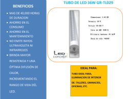
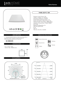
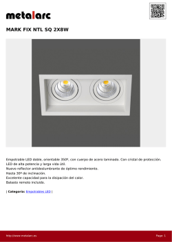
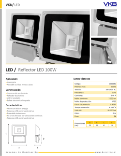
© Copyright 2026