
Glossary
Glossary
A
absolute coordinates (n) Coordinates associated with an origin that never changes location
and thus gives a stable method of locating
geometry in space. The absolute coordinate
system is also called the world or global coordinate system.
absolute scale (n) A data scale that has both a
defined zero point and units. The Kelvin temperature scale is an example of an absolute
scale.
actual size (n) A tolerancing measure used to
describe the size of a finished part after
machining.
additive (adj.) A process or state whereby elements combine together, such as two primitive
shapes combining to form a larger, more
complex one. Additive is the opposite of
subtractive.
additive primaries (n) The three primary colors: red, green, and blue. Color systems use
these primaries in differing amounts, working
on the principle of adding spectral wavelengths
to the light energy to create new colors. This
system is used in lighting and computer
display graphics. The complementary colors
are the subtractive primaries: cyan, magenta,
and yellow.
adjacent areas (n) Surfaces that are separated
on a multiview drawing by lines that represent
a change of planes. No two adjacent areas can
lie in the same plane.
adjacent view (n) Orthographic views that are
aligned to each other, allowing dimensional
information to be shared. Examples are the
front and top views or the front and right side
views.
aerial perspective (n) A perceptual cue where
objects farther away appear bluer and hazier.
The cue is based on the effect of particles in
the atmosphere blocking the passage of light.
aerospace engineering (n) A field of engineering concerned with the design and operation of
aircraft, missiles, and space vehicles.
aesthetics (n) The artistic qualities or aspects
that elicit an emotional response to an object.
agricultural engineering (n) A field of engineering concerned with production agriculture
and its natural resource base and the processing and chemistry of biological materials for
food and industrial products.
aligned dimensions (n) A style of dimensioning in which text is placed parallel to the
dimension line, with vertical dimensions read
from the right of the drawing sheet. The
aligned method of dimensioning is not
approved by the current ANSI standards but
may be seen on older drawings.
aligned section (n) A section view created by
bending the cutting plane line to pass through
an angled feature. The resulting section does
not show the section in true projection, yet it
gives the clearest possible representation of the
features.
allowance (n) A tolerancing measure used to
describe the minimum clearance or maximum
interference between parts. Allowance is the
tightest fit between two mating parts.
alphabet of lines (n) The standard linestyles
established by ANSI to be used for technical
drawing. The standards specify both the thickness and the design (i.e., dashed, solid, etc.) of
the lines.
alternate four-center ellipse method (n) A
method of creating an approximate ellipse. The
method is used for cavalier oblique drawings.
ambient light source (n) A light source
defined by its lack of orientation or location.
Fluorescent lighting in an office is an example
of ambient lighting. In renderings, an ambient
light source is sometimes used as a default
light source to give a baseline level of lighting
to the model.
analogous (adj.) A concept meaning similar or
comparable in some respects. The concept is
used to describe the extent to which a graphic
representation compares with a real object.
analysis by solids (n) A common technique
used for determining the multiview drawings
of a part by decomposing the object into geometric primitives, such as cylinders, prisms,
and negative cylinders.
analysis by surfaces (n) A common technique
used for determining the multiview drawings
of a part that has inclined and oblique surfaces.
analytic geometry (n) The analysis of geometric structures and properties, principally using
algebraic operations and position coordinates.
The term also refers to a particular geometric
method for describing 3-D solid models.
angle (n) The relative orientation of two linear
elements with respect to each other. The angle
is usually measured relative to the point of
intersection or termination of the two lines.
angularity (n) An orientation control for geometric dimensioning and tolerancing. Angularity is a condition of a surface, center plane, or
axis at an angle other than a right angle to a
datum plane or datum axis.
aperture card (n) A long rectangular card with
a rectangular hole for mounting microfilm.
apparent motion (n) The sense of motion
induced by rapidly displaying a series of
images of an object to make the object appear
to change location or shape. Animation techniques take advantage of this perceptual effect.
archiving (v) A term used to describe the storing and retrieval process for engineering documentation. Although originally involving paper
documents, the term increasingly refers to the
storage of computer-generated information on
magnetic or optical media.
area rendering (n) A data visualization technique in which the pixels in a 2-D area are
each assigned a value. A color lookup table
maps a specific color to each data value to create a rendered region.
array (n,v) Either the process of or resulting
geometry of a single feature being duplicated in
a regular fashion in a model. An array is procedural, in that instructions are given as to how a
feature(s) is to be duplicated rather than having
the user define the final location of each duplicate. Arrays are defined as being either linear or
radial, depending on how the duplication is
defined. Typically, the operator will indicate the
direction (in one or two dimensions) of the
duplication, spacing between each duplicate
feature, and how many duplicates to create.
G-1
G-2
GLOSSARY
arrow plot (n) A visualization technique in
which the dependent variable is a vector rather
than a scalar and is represented by line or
arrow marks. Because there are typically a
large number of arrow marks in a small region,
pattern (texture) perception can be used to
evaluate trends in the data.
artistic drawing (n) A type of drawing used to
express aesthetic, philosophical, and abstract
ideas. These types of drawings are not intended
to communicate clear, concise information pertaining to a design.
artwork drawing (n) See fabrication drawing.
assembly drawing (n) A drawing showing
how each part of a design is put together. An
assembly drawing normally consists of all the
parts drawn in their operating positions and a
parts list or bill of materials.
assembly section (n) A section view of multiple parts in an assembly. Differing section line
designs differentiate between different materials, or between similar materials belonging to
different parts.
augmented reality (n) A virtual reality system
that combines or overlays computer graphics
imagery with a normal view of a scene.
authoring (v) The process of using computer
programming tools to assemble different media
into an interactive presentation.
automation (n) The use of machinery in place
of human labor.
autorouting (v) A specialized software process
that suggests routing connections between
components on a circuit board. Autorouting is
usually part of a suite of CAD electronics
software functions that also include automated
component placement, programming of
CNC board drilling, and component insertion
equipment.
auxiliary section (n) A section view derived
from an auxiliary view. The term distinguishes
from section views derived from standard
orthographic views.
auxiliary view (n) A view derived from any
image plane other than the frontal, horizontal,
or profile planes. Auxiliary views are usually
termed primary or secondary, depending on
whether or not they are perpendicular to one of
the above-mentioned primary projection
planes. Primary auxiliary views are termed
depth, height, or width auxiliaries, depending
on the dimension transferred from the measuring view.
axis (n) The line or vector representing a center of rotation, such as the longitudinal center
line that passes through a screw thread cylinder. Also, a vector indicating a dimension in
model space or in a visualization such as a
graph.
axonometric axes (n) The axes used to define
the orientation of the primary dimensions in an
axonometric pictorial projection. The relative
angle of the axes to each other determines the
type of axonometric projection.
axonometric projection (n) A parallel projection technique used to create pictorial drawings
of objects by rotating the object on an axis relative to a projection plane.
B
B2B (B2C-e-marketplaces) (n) Business communities are beginning to form e-marketplaces,
enabling them to automate and leverage transactions with one another as a community. By
bringing together large numbers of buyers and
sellers, e-marketplaces give sellers access to
new customers, expand the choices available to
buyers and reduce transaction costs.
B-spline curve (n) A parametrically defined
freeform curve that approximates a curve to a
set of control points and provides for local control. Multiple 2-D curves are often combined to
create 3-D surface patches.
backface culling (n) In rendering, a preprocessing step that removes all faces of the model that
will be completely hidden from view.
bar graph (n) A graph (usually 2-D) in which
one dimension represents the independent variable and the other represents the dependent
variable. The magnitude of the dependent variable is represented by a line or area of uniform
width (a bar).
base feature (n) The first feature created when
defining a solid model. The base feature creates
the initial geometry of the model from which
additional geometry can be added or subtracted.
baseline dimensioning (n) A type of
dimension where a base line (or datum line) is
established for each Cartesian coordinate
direction and all dimensions are specified with
respect to those baselines. Also called datum or
rectangular coordinate dimensioning.
basic dimension (n) A tolerancing measure
used to describe the theoretically exact size of
a feature.
basic size (n) A tolerancing measure used to
describe the theoretical size used as a starting
point for the application of tolerances.
bearing (n) A mechanical device designed to
transfer radial or axial loads from a shaft while
minimizing energy loss due to friction from the
rotating shaft. Bearings are usually divided into
two general categories: plain and rolling contact.
Bezier curve (n) A special case of the B-spline
curve. Unlike a standard B-spline curve, the
Bezier does not provide for local control,
meaning that changing one control point
affects the entire curve.
BI (business intelligence) (n) Consolidates and
analyzes raw business data and turns it into conclusive actionable information. Enables companies to tap into disparate sources of customer,
operational, and market data and then use this
information to gain a competitive edge. It provides the intelligence needed to spot trends,
enhance relationships, reduce financial risk, and
create new sales opportunities.
bicubic surface patch (n) A 3-D freeform surface bounded by a set of curves described by
third-degree (cubic) functions. The bounding
curves, often B-spline or Bezier curves, and
their associated control points are used to
manipulate the shape of the surface.
bilateral tolerance (n) A dimensioning technique that allows variance in both directions
from the basic size of a part or feature.
bill of materials (n) A listing of parts or materials used in an assembled object. The listing is
usually included as part of the working drawing of the full assembly.
binary tree (n) A hierarchical, logical structure
used to organize related elements. Each node
on the tree is linked to exactly two leaves on
the next level down. Binary trees are used to
describe the relationship of geometric elements
in a CSG solid modeler.
bird’s eye view (n) In a perspective pictorial, a
viewpoint looking down from above the object.
From this viewpoint, the ground line is below
the horizon line of the object.
blind hole (n) A hole that does not go completely through the material. Blind holes can be
created by any cutting device (such as a twist
drill bit) that is capable of plunging into the
material.
block diagram (n) A relatively simple diagram
that quickly identifies the relationships between
systems, groups, people, or other physical or
abstract entities. (See also flow diagrams.)
blueprint (n) A photographic reproduction
process used to copy paper drawings.
boldface (adj.) A style of text in which the lines
that make up the letters are thicker than normal.
This technique is used to make words or letters
stand out visually from the rest of the text.
bolt (n) A mechanical fastening device with a
head on one end of an externally threaded
shaft. A nut is placed on the threaded shaft and
rotated to clamp the material between the head
and nut.
bonding (v) A process in which a material
(usually, a hardening liquid) is added to an
assembly to hold parts together. Bonding is a
permanent fastening method, using processes
such as welding, soldering, brazing, and gluing.
Boolean operations (n) Local operations used
to define the relationship between two geomet-
Glossary
ric objects. Boolean operations between new
and existing geometry are used extensively to
modify solid models in 3-D modeling
software.
bottom view (n) A principal view of an object,
created by rotating the object 90 degrees about
the horizontal axis below the front view. This
view is not typically included in a standard
multiview drawing.
boundary representation (B-rep) (n) A popular method of representing solid models. This
database structure describes the geometric and
topological elements of the surface of the
model. Unlike wireframe modeling, a B-rep
explicitly defines the surface of the model.
Unlike CSG modeling, a B-rep does not
explicitly define the interior volume of the
object.
bounding box (n) An imaginary box representing the maximum dimensions of the object
being drawn. Sketches of objects often begin
with this box, and it is used to define the
boundaries and guide the placement of individual features.
brainstorming (v) A process used to identify
as many solutions to a design problem as
possible by freely suggesting ideas without
criticism or discussion of feasibility. A brainstorming session will normally have a moderator and a recorder.
break lines (n) Freehand lines used to show
where an object is broken to reveal interior features of a part. Such lines can also be used to
show where a portion of a line or object has
been left out for clarity or because of space
limitations.
broken-out section (n) A section view used to
reveal interior features of a part by breaking
away a portion of the object. A broken-out section is often used instead of a half or full section view when the feature of interest is not
symmetrical with the overall object. The result
is a more efficient drawing. Unlike most other
section views, a cutting plane line is not
defined in an adjacent view.
bump mapping (n) A rendering technique
used to add surface detail to a model. Bump
mapping perturbs the normals used in shading
the surface polygons in such a way as to give
the impression of a regularly undulating
surface (i.e., texture). A golf ball could be represented as a shaded sphere, with the dimples
created through bump mapping.
C
cabinet oblique (n) A type of oblique pictorial
drawing in which the two dimensions of the
frontal surface are drawn parallel to the frontal
plane, and the third (receding) axis is drawn
obliquely at half the scale of the frontal plane.
The receding axis is typically drawn at an
angle of between 45 and 60 degrees.
cabling diagram (n) See wiring diagram.
CAD (v or n) Acronym for computer-aided
drafting, computer-aided design, or computeraided design/drafting. The usage depends on
the context in the design process and on
whether the acronym refers to the physical
computer system or the activity of using such a
system to support technical and engineering
graphics.
callouts (n) See line balloon.
cam (n) A mechanical device used to transform
rotary motion into reciprocating motion, using
a rolling or sliding contact with another part
called a cam follower. Radial cams move the
follower perpendicular to the shaft; cylindrical
cams move the follower parallel to the shaft.
The shape of the contact surface determines
the motion of the follower.
CAM (n) Acronym for computer-aided manufacturing, which is the use of computers to
control the production process. Examples are
robots for assembly and numerically controlled
machine tools. CAM is often combined with
CAD to describe the integration of design and
manufacturing through the use of a common
computer database.
cam follower (n) A mechanical device in
which one end follows a linear, reciprocating
path as the other end traces the surface of a
rotating cam. Followers are often spring loaded
to guarantee a good contact with the surface of
the cam.
cap screw (n) A mechanical threaded fastener
with a head on one end, used to screw into a
mating part. Differing from a bolt, a cap screw
has a longer thread length and does not use a
nut.
CAPP (n) Acronym for computer-aided
process planning, a technique that uses computers to assist in the planning process. CAPP
is an expert computer system that can be used
to determine the optimal sequence of operations for a part and can then generate the optimal process and routing sheets necessary to
make the part.
Cartesian coordinate system (n) Common
coordinate system used in mathematics and
graphics to locate the position of geometry in
space. First introduced in 1637 by Rene
Descartes (1596–1650), the system is typically
used to locate points in 2-D (X,Y) or 3-D
(X,Y,Z) space by assigning values to the points
based on the mutually perpendicular (orthogonal) axes.
cavalier oblique (n) A type of pictorial drawing in which the two dimensions of the frontal
surface are drawn parallel to the frontal plane,
G-3
and the third (receding) axis is drawn obliquely
to the frontal plane and at the same scale. The
receding axis is typically drawn at an angle of
between 45 and 60 degrees.
CAVE® (n) A multiple projection based virtual reality system consisting of multiple
screens and projectors configured into walls,
floor, and ceiling to create a room is called a
CAVE® (Cave automatic virtual environment).
CD-ROM (n) Acronym for compact disc-read
only memory, a mass storage device that uses optical technology to store large amounts of information on a small reflective platter. Information is
written to the disk only once, at which point the
disk is unchangeable. CD-ROMs are used for
archiving audio, graphic, and textual information
and for publishing and distributing software,
graphic images, multimedia materials, etc.
center lines (n) A type of linestyle used to represent symmetry and paths of motion and to
mark the centers of circles and the axes of
symmetrical parts, such as cylinders and bolts.
Unlike visible and hidden lines, center lines do
not represent geometry directly.
central view (n) The view from which related
views are aligned in an orthographic drawing.
Distances and features are projected or
measured from the central view to create the
adjacent views.
ceramics (n) Materials, usually with crystal
structures, created from compounds of metallic
and nonmetallic elements. Ceramics can withstand high temperatures and resist wear. Some
ceramics, such as glass, are not crystalline in
structure.
chain line (n) A type of line in the alphabet of
lines represented by alternating short and long
dashes.
chamfer (n or v) A beveled corner used on the
opening of a hole and the end of a cylindrical
part to eliminate sharp corners. Chamfers facilitate the assembly of parts and are specified by
giving a linear and angular dimension. When
used as a verb, the term refers to the process of
creating a chamfer on an object.
change of planes (n) A feature sometimes
called a corner which occurs when two nonparallel surfaces meet, forming an edge.
check print (n) A type of hard-copy output
used to check the accuracy and format of a
technical drawing. The check print is a lowquality, high-speed method of troubleshooting
the final print or plot.
chemical engineering (n) A field of engineering that includes all phases of technical activities in which a knowledge of chemistry, along
with other basic sciences, is used to solve
problems related to energy, health, the environment, food, clothing, shelter, and materials.
G-4
GLOSSARY
CIM (n) Acronym for computer-integrated
manufacturing, a system for linking manufacturing operations into a single integrated computer system. CIM differs from CAD/CAM
primarily in its integration of business
functions, such as accounting, marketing, and
personnel, into a common computer database
shared by all components of the business.
circle (n) A closed, planar curve that, at all
points, is an equal distance (the radius) from a
point designated as the center. A circular arc is
an open, planar curve equidistant from a center. The arc will subtend an angle of less than
360 degrees. A circle is sometimes described as
a 360-degree arc.
circuit side (n) The side of a printed circuit
board on which a majority of the circuit connections for components are made. The opposite side of the board is called the component
side.
circularity (roundness) (n) A form control for
geometric dimensioning and tolerancing. For a
cylinder or cone, circularity means that all
points on a surface intersected by a plane passing perpendicular to a common axis are
equidistant to that axis. For a sphere, all points
on a surface intersected by a plane passing
through the center are equidistant to that center.
circular line element (n) A geometric control
used in GDT that is any single line on the surface of a cylinder and perpendicular to the axis
of the cylinder.
civil engineering (n) A field of engineering
involved with planning, design, construction,
operation, and maintenance of transportation,
environmental, and construction systems.
Along with military engineering, this field is
often considered the first true engineering field.
clash (v) A condition in which two parts of a
mechanism partially overlap in space, causing
interference. Kinematic analysis using the
Boolean intersection operation is often used to
evaluate clashes in computer models of the
mechanism.
clearance fit (n) A tolerancing measure used to
describe a fit in which two mating parts always
leave a space when assembled. The resulting
space is called an allowance or a clearance and
is usually specified in the assembly drawings.
clip (v) The rendering process of removing
portions of lines or surfaces that reside outside
the view volume. Clipping refers to removing
the portion of the model that resides outside
the horizontal and vertical bounds of the viewing area and outside the specified near and far
depth (Z) bounds.
clock speed (n) The rate at which the central
processing unit (CPU) of a computer performs
functions. The clock speed is measured in
megahertz (MHz). The higher the clock speed,
the more powerful the CPU.
closed loop (n) The condition required for a
group of edges to form a face (surface) on an
object. The edges must be connected end to
end, forming a continuous path around the
perimeter of the face.
CNC (n) Acronym for computer numeric control, which describes a form of programmable
automation of a machine tool using a computer
in the controller unit. In a computer-controlled
manufacturing center, the individual machines
would use CNC programs, either sent from a
main computer or programmed locally.
collaborative engineering (n) An integrated
product development process to create a highly
effective team collaboration environment.
color (n) The perceptual quality of a surface
that results from the combined response to
lightness, hue, and value. Hue is often
confused with color since the names of hues
(e.g., red, purple, yellow, etc.) are used as the
primary classification terms for color.
color lookup table (n) A modular database
that allows colors to be mapped to specific data
values in a visualization. The color lookup
table can be associated with a single rendered
image or be used as a standard table in a
library. Color lookup tables are often referred
to as palettes.
command history (n) A listing of commands
entered into the CAD system by the user, along
with the values of the specified parameters.
Command histories can be used as a “script” to
replay sequences of commands or track down
input errors.
composites (n) The combination of two or
more materials, one a reinforcing element and
the other a resin binder or matrix. A common
composite is fiberglass, which is made of glass
fibers and a resin. The more advanced reinforcing elements include carbon/graphite, boron,
and Kevlar (aramid), which are stiff, strong,
and lightweight.
computer animation and simulation (n) Simulation is the precise modeling of complex situations that involve a time element; animation
is the imprecise modeling of complex
situations over time. An animation will replicate a real situation by approximate means; a
simulation will replicate a real situation by
accurate means.
computer numeric control (CNC) (n) See CNC.
computer-aided drafting/design (CAD) (n)
See CAD.
computer-aided manufacturing (CAM) (n)
See CAM.
computer-integrated manufacturing (CIM)
(n) See CIM.
concentricity (n) A condition in which the axes
of all cross-sectional elements of a cylinder,
cone, or sphere are common to a datum axis.
conciseness (adj.) A term used to describe one
attribute of a CAD database. The more concise
the database, the less space each record takes
in the hard drive of the computer.
concurrent (adj.) The technique of organizing
numerous steps so that they happen in parallel
rather than one after another (serially). Concurrent engineering, for example, involves all
members of the design process working simultaneously in close coordination with each other
rather than each member waiting for other
members to finish with their components of the
design.
cone (n) A geometric solid described by a
straight line (the generatrix), one end of which
is attached to a fixed point (the vertex) and the
other end of which traces a closed, curved
path. The most common cone is a right circular
cone, for which the curved path is a circle and
the vertex lies on an axis that is perpendicular
to the circle and through its center.
cone of vision (n) A term used to describe the
amount of space visible by the human eye
looking in a fixed direction. The visible
volume is approximately described by a rightangled cone for which the vertex is at the eye
and the axis is aligned with the view direction.
conics (n) Special case single-curved lines that
can be described in many different ways: sections of a cone, an algebraic equation, and the
locus of points. For our purposes, conics are
sections of a right circular cone and include the
ellipse, parabola, and hyperbola. The circle is a
special-case conic.
connection list (n) The list of all connections
that need to be made between components on
an electronic circuit board. This list is usually
managed by the electronic CAD program.
connectors (n) Devices used to join electronic
components together to allow the transmission
of signals. Connectors include plugs (external
components) and jacks or receptacles (internal
components) and can provide either temporary
or permanent connections. Devices used for
mechanical connection are typically called
fasteners.
constant pitch series thread (n) A type of
thread used for special purposes.
constraint (n) A mathematical requirement
placed on geometric elements in a 3-D model.
Dimensional constraints define the distance
between two geometric elements while geometric constraints define a relationship such as parallelism or perpendicularity between elements.
The operator establishes an explicit constraint
while the software automatically places an
implicit constraint. A fully constrained feature
has all of its geometry unequivocally defined
while an underconstrained feature does not. An
overconstrained feature has conflicting geometric requirements.
Glossary
construction geometry (n) Any geometry created as part of the CAD modeling process that
does not represent actual part geometry. An
example of this would be workplanes, axes, or
points used to locate geometry in a solid
model.
construction lines (n) Light, thin lines drawn
to lay out the framework or structure of a
drawing or sketch. Portions of these lines are
often overdrawn with the final linework.
constructive solid geometry (CSG) (n) A
method of 3-D solid modeling in which geometric primitives are related to each other in a
binary tree structure via Boolean operations.
Each primitive is defined as a solid by a group
of analytic surfaces (half-spaces), and the final
object is defined by the calculation of the
Boolean operations between primitives.
continuity (n) A term used to describe the
transition between two elements. Elements are
continuous if there is no gap or break between
them, and there is a single mathematical function used to describe the two combined
elements. Continuity is often used to describe
the connection of two curved lines or surfaces.
contour line (n) A line that represents the independent variable (X,Y) combinations that
result in a constant dependent variable value
(also called an isoline). A contour line can also
represent the juncture between two surfaces of
differing orientations or depths. In this definition, a contour line is an alternate term for
edge.
contour plot (n) A visualization in which the
horizontal and vertical scales both represent
independent variable values, and the contour
lines show the mapping of constant, dependent
variable values. Multiple contour lines are typically drawn on a plot, representing a uniform
sampling of dependent variable values.
contour sketch (n) A technique to develop the
visual acuity of a novice sketcher by sketching
the outline of an object.
control points (n) Points used in conjunction
with spline curves. These points are not part of
the curve proper, but the relationship between
the control points and the points on the curve is
used to define the shape of the curve.
controlling (v) The procedures used to control
materials, machines, and processes in the manufacturing and production cycle through
automation, measuring, inspection, and testing.
conventions (n) Commonly accepted
practices, rules, or methods. In technical drawing, a convention is the use of dashed lines to
designate a feature hidden from the current
viewpoint.
convolute (n) A single-curved surface generated by a straight line moving such that it is
always tangent to a double-curved line.
Coons’ surface (n) A 3-D surface defined by
input curves. This surface was named after
Steven A. Coons, who developed the
mathematical method for defining complex
shapes used in the design of aircraft, automobiles, and ships’ hulls.
coordinate dimensioning (n) A technique in
which all dimensions are calculated as Cartesian X and Y distances from an origin point,
usually located at the lower left-hand corner of
the part. Also known as datum dimensioning or
baseline dimensioning, coordinate dimensioning should be used cautiously because of the
tolerance stackup that takes place.
coordinates (n) A set of real numbers defining
the location of a point in space. One value is
given for each dimension of the space (i.e.,
2-D, 3-D), and each value is determined by
the point’s distance from the defined origin.
corner (n) The nontangential intersection of
two or more surfaces of an object. The intersection of two surfaces is usually referred to
as an edge. Corners are represented on a
drawing by either a single line or multiple
co-terminating lines.
counterbored hole (n) A type of hole that has
been enlarged at the top to allow heads of bolts
to be flush with or below the surface of the
part.
countersunk hole (n) A type of hole that has
been enlarged at the top to allow heads of flat
head fasteners to be flush with or below the
surface of the part.
course series thread (n) A type of thread used
for quick assembly or disassembly which is
designated as NC or UNC on drawings.
CPU (n) Acronym for central processing unit.
The CPU is the heart of the computer, coordinating all primary activities of the computer
and processing a majority of operations or
“calls” from the software. Computers are often
classified by their CPUs. Examples are Intel’s
PentiumTM and Motorola’s PowerPCTM 601.
crest (n) A threading term describing the peak
or top surface of a screw thread.
CRM (customer relationship management)
(n) Use proven methodologies and e-business
technologies to help enable companies to identify, select, acquire, develop, and retain profitable
customers, building the lasting relationships that
are key to long-term financial success.
cross-hatch lines (n) An alternate term for section lines. Cross-hatch often refers to section
line symbols in which the lines cross each
other rather than simply running parallel to
each other.
curved line (n) A line which does not follow a
straight path. Curved lines are often classified
by their underlying mathematical functions.
Examples are circular and elliptical curves.
G-5
cutting plane (n) An imaginary plane in space
used to define the division between two parts
of an object. A cutting plane is often used to
define a portion of an object to be removed in
order to reveal the interior detail.
cutting plane lines (n) A line showing the
location of a cutting plane in section drawings.
The cutting plane line is drawn in the view for
which the line of sight is parallel to the cutting
plane. Arrows on the ends of the section line
point toward the material to be retained in the
corresponding section view.
cycle time (n) The total time required for a
process to take place.
cycloid (n) A curve generated by the motion of
a point on the circumference of a circle that is
rolled in a plane along a straight line.
cylinder (n) A planar geometric solid
described by a straight line (the generatrix) that
traces a closed, curved path and always stays
parallel to itself. The most common cylinder is
a right circular cylinder for which the curved
path is a circle and the generatrix is perpendicular to the path.
cylindrical coordinates (n) A system for locating points in space with one angle and two
lengths. Cylindrical coordinates describe a
point as a distance from the origin, its angle in
the X–Y plane, and its Z value. Cylindrical
coordinates are useful when designing circular
shapes and geographic applications.
cylindricity (n) A form control for geometric
dimensioning and tolerancing. Cylindricity
indicates that all points on the surface should
be equidistant from a common axis. Unlike circularity, cylindricity refers to both the circular
and the linear (longitudinal) elements on the
surface.
D
data region (n) The region in a visualization
where the actual data is represented. In a graph
or plot, the region would be bounded by the
scales (axes) where the point or line markers
representing the data are drawn.
data visualization (n or v) The method or end
result of transforming numeric and textual
information into a graphic format. Visualizations are used to explore large quantities of
data holistically in order to understand trends
or principles.
datum (n) A theoretically exact point, axis, or
plane used as a reference for tabular dimensioning. A datum marks the origin from which
the location and orientation of geometric features are established.
datum dimensioning (n) A type of dimension
where a base line (or datum line) is established
for each Cartesian coordinate direction and all
dimensions are specified with respect to those
G-6
GLOSSARY
baselines. Also called rectangular coordinate or
baseline dimensioning.
datum feature (n) A term used in geometric
dimensioning and tolerancing to describe a real
or theoretical feature selected to ensure the
proper orientation or location of other features
on a part. Controls define features on the part
relative to the datum features.
datum feature symbol (n) A symbol on a
drawing to identify the features used to create
the datums.
datum reference frame (n) A term used in
geometric dimensioning and tolerancing to
describe the theoretical reference frame used to
evaluate the location and orientation of
features of a part. The frame consists of three
mutually perpendicular (orthogonal) planes,
which typically correspond to the principal
planes of projection in a multiview drawing or
the global coordinate system in a 3-D modeling system. In inspections, a physical surface
may be established to simulate one of the reference planes.
declarative information (n) A term used to
describe the current state of an object. This
type of information can be thought of as
descriptive nouns. The location of a point in a
coordinate system (8,3,5) is an example of
declarative information.
density slicing (n) A visualization technique,
used with area and volume renderings, in
which a particular data value or small range of
values is highlighted in contrasting color. This
technique can be used either for a single static
image or for sequential images highlighting
different data values in the image.
dependent variable (n) A variable
dependent on the response of the model and
not controlled by the experimenter. Every
dependent variable value is paired with one or
more independent variables and represents the
model’s response to the independent variable
values.
depth (n) One of the three principal dimensions of an object. The depth dimension is
described in the right side and top views of a
multiview drawing. The depth dimension is
often associated with the Z axis in a 3-D modeling system. Depth can also refer to the distance cut into an object using a machining
process (e.g., the distance measured between
the crest and root of a thread normal to the axis
or the depth of a drilled hole).
descriptive geometry (n) The fundamental
basis of the science of projection drawing,
attributed to the work of Gaspard Monge
(1746–1818). It is the basis of all types of 3-D
representations on 2-D media used today.
design analysis (n) The evaluation of a
proposed design during the refinement process,
using the criteria established in the ideation
phase. The refinement stage is normally the
second of three major phases in the design
process.
design for manufacturability (DFM) (n) A
technique in which ways are found to simplify
a design and reduce manufacturing costs. Using
CAD/CAM technology, DFM determines the
manufacturability of a design before it is
produced.
design intent (n) A phrase describing the integration into the model of how feature dimensions and geometry relate to each other in
order to satisfy the design constraints of the
final product. Design intent is usually embodied in the model through the definition of features and their constraints.
design process (n) The method used to create
a solution to an engineering or technical problem. The result is often a product, either one of
a kind or mass produced. The design process,
though unique to each problem, typically
includes standard stages and uses graphics to
communicate information between and within
these stages.
design review (n) A formal meeting where
the design team presents their progress to
management.
design visualization (n) A process using the
fundamental capabilities of a human visual
system; the ability to perceive 3-D form, color,
and pattern. Visualization is an analysis
method used in the second stage of the design
process, the refinement phase.
detail drawing (n) A dimensioned multiview
drawing of a single part, using ANSI standard
conventions to describe the part’s shape, size,
material, and finish. Detail drawings are sufficiently descriptive that the part can be manufactured using the drawing as the only
communications device. Detail drawings are
produced from design sketches or extracted
from a 3-D computer model.
development (n) An alternative description of
the surfaces of a 3-D object as a 2-D pattern.
The creation of a development is often thought
of as an unfolding of the surfaces of an object.
A developable surface, then, can be unfolded
or unrolled onto a plane without distortion.
Single-curved surfaces, such as cylinders and
cones, are also developable.
deviation (n) A tolerancing measure used to
describe the difference between the size of a
produced part and the basic size.
DFM (n) See design for manufacturability.
diameter symbol (n) A symbol used in ANSI
dimensioning that precedes a numerical value,
indicating that the value shows the diameter of a
circle. The symbol used is the Greek letter phi (ø).
diazo (n) A type of print process used to copy
paper drawings.
difference (−) (n) The Boolean operation that
subtracts, or removes, the intersecting geometry from the specified solid. For example, in
the Boolean operation A − B, the intersection
of solids A and B is removed from A.
diffuse (adj.) A term describing a reflection
of light that strikes a surface and reflects uniformly in all directions, creating no highlights
or hot spots.
digital enterprise (n) A model that facilitates
the simultaneous working of many
departments in a company.
digital terrain model (DTM) (n) A 3-D computer model of a landform generated from survey data. Such models are often used by civil
engineers and land planners to explore possible
placements of structures or changes to the terrain before actual construction begins.
dihedral angle (n) The angle between two
planes. Finding the true measurement of a
dihedral angle requires an edge view of the two
planes and is a common application for the use
of auxiliary views.
dimension (n or v) The physical size of an
object, or the process of documenting physical
sizes. The number of dimensions used to
describe the object depends on whether length
(1-D), area (2-D), or volume (3-D) is being
measured. Dimensioning can also refer to the
measurement of size, location, and orientation
of particular features on an object.
dimension line (n) A thin, solid line that shows
the extent and direction of a dimension. Dimension lines are paired with the number representing the physical size of the feature, and extension
lines are used to associate the dimension to the
corresponding feature on the drawing.
dimetric projection (n) An axonometric projection in which two of the three axes have the
same scale and the same angle relative to the
third axis. A dimetric drawing is less pleasing
to the eye than a trimetric projection but is easier to draw.
direct data exchange (n) A method of data
exchange between CAD systems. Data is
directly translated from the format native to one
system to the format native to another system.
direct view (n) A descriptive geometry technique (sometimes referred to as the natural
method) that places the observer at an infinite
distance from the object, with the observer’s
line of sight perpendicular to the geometry in
question. In third-angle projection, a projection
plane is placed between the observer and the
object, and the geometry is projected onto the
projection plane.
directrix (n) A line (typically curved) that
describes the path of a straight line (the generatrix). The path of the generatrix along the
directrix describes ruled surfaces or solids.
Glossary
discretization (n) The method of dividing
more complex geometry into simpler geometry. A discretized model can be manipulated
using techniques such as finite element analysis, in which all the simple geometric components of a model are evaluated simultaneously.
displacement (n) The linear or angular
distance moved by a part or mechanism. In
cam design, a displacement diagram is used to
chart the linear location of the follower relative
to the angular position of the cam.
displacement diagram (n) A graph or flat pattern
drawing of the travel of the follower on a cam.
display devices (n) The hardware used to display output text and graphics of computer software, such as CAD. The most common display
device is the cathode ray tube, or CRT, used in
computer monitors.
dither pattern (n) A method of simulating
varying value (gray) levels within an image
when only one color of ink (usually black) is
available. The patterns are achieved by grouping square matrices of pixels in an image (e.g.,
3 × 3) and coloring a pattern of pixels in the
matrix, based on the average value level in the
matrix region. Because of the small size of the
pixels relative to the size of the image, the
pixel patterns give the impression of value
changes when viewed at a distance.
documentation (n) The process used to formally
record and communicate the final design solution.
document sketches (n) A more formal type of
freehand sketch used during the refinement
stage of the design process. These sketches
often contain many of the conventions found in
more formal drawings.
domain (n) A term that describes the types of
objects that can or cannot be represented by a
computer modeler. The larger the domain, the
greater the number of objects the CAD system
can describe.
donut (n) See feed-through.
double-curved surface/line (n) A surface or
line that curves in two orthogonal dimensions
at the same time. A sphere is an example of a
double-curved surface.
double-line drawing (n) See piping drawing.
drawing number (n) Drawings used in industry are assigned a number which is normally
placed in the title block.
drill drawing (n) See fabrication drawing.
drawing exchange format (n) See DXF.
drilling (v) A process that uses a rotating cutting tool to produce holes. It can also refer
more specifically to a process that produces
holes using twist drill bits.
DTM (n) See digital terrain model.
DXF (n) Acronym for drawing exchange format, a nonproprietary CAD data format devel-
oped by Autodesk to facilitate the exchange of
CAD-based graphic information. It has become
a de facto neutral data exchange format for the
microcomputer CAD industry.
dynamic analysis (n) The evaluation of a
design as it changes over time. Unlike kinematic
analysis, dynamic analysis assumes that forces
(e.g., gravity, angular momentum) are both
acting on and created by the mechanism being
analyzed.
E
E-business (n) The process of using Web technology to help businesses streamline processes,
improve productivity, and increase efficiencies.
Enables companies to easily communicate with
partners, vendors, and customers, connect
back-end data systems, and transact commerce
in a secure manner.
E-business infrastructure (n) The hardware
and software technology necessary to support
the day-to-day activities in the digital enterprise.
ECO (n) See engineering change order.
E-commerce (n) The ability to buy and sell
products and services over the Internet.
Includes online display of goods and services,
ordering, billing, customer service, and all handling of payments and transactions.
edge (n) The intersection or boundary of two
nontangential surfaces (faces). An edge is represented on a technical drawing as a line or a
change in shading gradients in a rendered
image.
edge view (n) The view of a surface such that
it is seen as a line. For a planar surface, the
edge view is an orthographic view parallel to
the plane in which the surface resides.
efficiency (adj.) With respect to CAD, the
speed with which software can execute a command. This is reflected in the amount of computer processing time required to execute a
command.
elastomers (n) A special class of polymers that
can withstand elastic deformation, then return
to their original shape and size. Natural rubber,
polyacrylate, ethylene propylene, neoprene,
polysulfide, silicone, and urethane are types of
elastomers.
electrical engineering (n) A field of engineering that includes the research, development,
design, and operation of electrical and
electronic systems and their components.
elevation drawing (n) A type of drawing commonly used in civil, architectural, or engineering projects involving large structural layouts.
An elevation drawing (sometimes called an
elevation view) is an orthographic view
perpendicular to the line of gravity (i.e., parallel to the terrain). These drawings are useful in
planning the vertical arrangement of compo-
G-7
nents within a structure, or of the structure relative to the terrain, and are also used to make
aesthetic judgments since this view closely
matches how the structure would be seen.
ellipse (n) A single-curved line primitive. An
ellipse is a conic section produced when a
plane is passed through a right circular cone
oblique to the axis and at a greater angle with
the axis than the elements. An ellipse also
describes a circle or circular arc viewed at any
angle other than normal (perpendicular).
engineer (n) A professional concerned with
applying scientific knowledge to practical
problems. The discipline is divided into a number of specialties, such as civil, mechanical,
chemical, electronic, aerospace, electrical, and
industrial engineering.
engineering change order (ECO) (n) A
document that begins the process for making
changes in a design. Normally, the ECO will
be documented in an engineering change note
(ECN). A copy of the engineering drawing is
attached to the order, with sketches and a written description of the change. A reference number is given to the change order so that it can
be traced within the organization.
engineering design (n) A process used to
design a new system or process.
engineering digital management system
(EDMS) (n) Database software tool used to
manage digital drawing files.
engineering graphics (n) A communications
method used by engineers and other technical
professionals during the process of finding
solutions to technical problems. Engineering
graphics are produced according to certain
standards and conventions so that they can be
read and accurately interpreted by anyone who
has learned those standards and conventions.
enterprise data management (EDM) (n) A
process using computer software to track CAD
or office documents. Sometimes called enterprise document management (EDM).
enterprise document management (EDM)
(n) A process using computer software to track
CAD or office documents. Sometimes called
enterprise data management (EDM).
envelope principle (n) A term used in geometric dimensioning and tolerancing to describe
how much a feature can deviate from ideal
form, orientation, or position as it departs from
maximum material condition.
equal measure projection (n) Also called an
isometric projection. A type of pictorial projection created when all three angles of the axonometric axes are equal.
ergonomics (n) A technical field concerned
with optimizing the interface between humans
and technology. The field has numerous
specialties, including industrial safety and
G-8
GLOSSARY
hygiene, human–computer interface design,
and the design of control panels in manufacturing plants, cars, airplanes, etc.
ERP (enterprise resource planning) (n) Helps
businesses streamline and manage critical operations such as inventory maintenance, supplier
interaction, product planning, purchasing, customer service, and order tracking. Supported by
multi-module application software, it links
together fragmented operations and shares data
across an integrated set of application modules.
error bar (n) A mark added to data points in
graphs and plots to indicate the range of probable values. Since perfect accuracy is not possible in any kind of experimental method, the
error bar represents the degree of certainty in
the data value. The length of the bar usually
represents the statistic of standard deviation.
error checking (v) The process of evaluating
actions requested by the operator to determine
if such actions resulted in invalid geometry.
Depending on the system, error checking may be
done automatically (such as when a file is saved
to disk) or manually at the request of the user.
etching (n) The method of creating patterns,
typically in metal, using chemical processes.
In the electronics industry, etching is used to
remove conductive material, usually copper,
from printed circuit boards to create wiring
patterns. The wiring pattern is printed on the
board in a chemically resistant ink, and the rest
of the conductive material is then dissolved
away in a chemical bath.
Euler operations (n) Low-level operations
used to construct models from geometric primitives, such as vertices, edges, and faces. The
validity of the model is guaranteed by a simple
mathematical formula, credited to both
Leonhard Euler (1707–1783) and Jules Henri
Poincaré (1854–1912).
evaluated (adj.) A description of a model for
which the final form is explicitly represented in
the database. An evaluated model is not concise (it may take up large amounts of memory),
but it is efficient (calculations on the model are
processed quickly).
exploded assembly (n) An assembly drawing,
usually a pictorial, in which the parts of the
assembly are spread apart (exploded) from
their functional location in order to provide a
larger, clearer view of the features of the individual parts. Flow lines are used to relate the
parts to each other and to demonstrate assembly. This type of assembly drawing is used
extensively for technical illustrations in such
applications as parts catalogs and assembly
instructions.
exposure (n) The orientation of a principal surface of an object relative to the image plane.
The greater the exposure, the closer the
surface(s) is to being parallel to the image
plane and, therefore, the lower the distortion
caused by foreshortening.
extension line (n) A thin, solid line perpendicular to a dimension line, indicating which feature is associated with the dimension.
extra fine series thread (n) A type of thread
used when the length of engagement is short and
the application calls for high degrees of stress
and are designated NEF and UNEF on drawings.
extranet (n) Private secure networks that allow
access to a company’s internal intranet by outside entities.
F
fabrication drawing (n) An electronics drawing that presents the complete engineering for
the manufacture of a printed circuit board. The
fabrication drawing contains an accurate toscale layout of the board shape, drill hole locations, material and manufacturing specifications,
and conductor pattern. The conductor pattern is
broken out to make an artwork drawing, a
screen print drawing, and the mask used in
board etching. The drill hole information is
sometimes broken out into a separate drill drawing for use in programming the drill patterns.
face (n) A distinct planar or curved surface or
region on an object. One or more faces joined
together at edges define the boundary between
object and nonobject. A face is a topological
element in a 3-D model.
face-edge-vertex graph (n) The data structure
used by boundary representation (B-rep) 3-D
solid modelers. The graph contains both geometric information on the location and size of
geometric elements and topological information on how they are linked together.
facets (n) Repeating groups of polygons of
similar topology, forming an approximate representation of a curved surface. Curved
surfaces such as cylinders and spheres are subdivided into a series of faceted planar surfaces,
which approximate the original surface. This
transformation is often used so that curved surfaces can be rendered using algorithms that
only support planar surfaces.
faithful (adj.) A measure of whether a
computer model contains or imparts sufficient
information to fulfill its task. In order to define
the faithfulness of a model, the exact use of the
model must be known.
familiar size (n) A perceptual cue in which the
known (familiar) size of an object is used to
judge its distance from the observer. Often, the
comparison of the perceived size of two
objects is used to judge their relative locations
in depth.
family of parts (n) Similar parts that can be
grouped together. A family of parts might be a
series of air cylinders that have many common
topologies but have variations in the geometry
of certain features, such as the diameter or
length of the head. Parametric techniques can
be used to represent a family of parts on the
computer or in drawings.
fastener (n) A mechanical device that
constrains two or more parts. Fasteners can
rigidly join parts or can allow certain degrees
of freedom. Some fasteners are meant to be
disassembled for maintenance (e.g., screws and
bolts), while others are considered permanent
(e.g., rivets).
feature (n) A general term applied to physical
portions of a part. Features typically serve a
function, either in the final application of the
part or in the specification or manufacture of it.
Examples are a hole, slot, stud, or surface.
feature control frame (n) A rectangular outline containing geometric dimensioning and
tolerancing information used in the engineering, production, and inspection of a part. The
left-hand compartment inside the frame contains the symbol of the geometric control being
applied. The middle compartment contains the
size of the tolerance zone. The right-hand compartment contains the datum identification
symbol(s).
feature of size (n) A feature that is measurable;
specifically, a spherical or cylindrical surface,
or a pair of parallel plane surfaces, associated
with a feature.
feature tree (n) A computer interface element
common to most constraint-based solid modelers. The feature tree lists the geometric features
contained in the model in the order in which
they are interpreted by the modeler. New features will typically be placed at the bottom of
the tree. A feature in the tree can be construction geometry, part features, or components in
an assembly.
feed-through (n) A through-hole in a printed
circuit board which has a conductive surround
on at least one side of the board and sometimes
in the hole. The conductive pads or donuts on
either side of the hole are used to make electrical
connections through the board and with component wires that are soldered into the holes.
FEM/FEA (n) See finite element modeling and
analysis.
fillet (n) A rounded interior corner normally
found on cast, forged, or molded parts. Like a
round, a fillet can indicate that a surface is not
machine finished. A fillet is indicated on engineering drawings as a small arc.
finance process (n) Used to analyze the feasibility of producing a product relative to capital
requirements and return on investment (ROI).
fine series thread (n) A type of thread used when
a great deal of force is necessary for assembly
which is designated NF or UNF on drawings.
Glossary
finish mark (n) A mark placed on the edge
view of a surface used on an engineering drawing to indicate that a surface is to be machine
finished.
finite element modeling and analysis
(FEM/FEA) (n) An analysis technique used
extensively to model and analyze forces within
a computer model or a proposed design. In the
modeling phase, the continuous surface or volume is discretized into a finite number of
linked primitive geometries. In the analysis
phase, the model is subjected to theoretical
forces applied at certain locations, and the
resulting forces are calculated across the rest of
the model.
fish-tank VR (n) A desktop computer system
in which a stereo image of a 3-D scene is
viewed on a monitor.
fittings (n) A term used to describe components that connect pipes, valves, and other
fluid and gas-handling equipment. Fittings are
often classified by the method used to join the
components together. Some of the most common types are welded, threaded, and flanged
(bolted).
fixture (n) A rigidly held production tool that
securely holds, supports, and locates the workpiece. Unlike a jig, a fixture is not used to
guide a cutting tool.
flat shading (n) A rendering method that uniformly adjusts the value of a surface color
based on its orientation to the light. This
method is considered the simplest shading
method since it only requires the calculation of
a single surface normal.
flatness (n) A form control for geometric
dimensioning and tolerancing. Flatness
indicates that all points on the surface must lie
in a plane. Flatness for a planar surface is comparable to straightness for a line.
flexible manufacturing system (FMS) (n) A
group of machines that can be programmed to
produce a variety of similar products. For
example, an automobile parts supplier might
specialize in the production of gears for transmissions. An FMS cell might be used to produce the gears for more than one automobile
manufacturer because the parts are similar.
flow charts (n) A visualization technique for
displaying relationships in time, particularly
for data that doesn’t conform well to scalar
mapping. PERT charts and other types of flow
charts are project management tools used to
map the relationship of specified project tasks,
personnel, and other resources on a single
timeline.
flow diagram (chart) (n) A diagram used in
electronic and piping systems to describe the
system’s process and the flow of material (or
electronic signals) through the proposed design.
Since these diagrams only depict the functional
nature of the system, they do not show the true
spatial layout or geometry of the components.
flow lines (n) Lines used primarily in technical
illustrations to indicate the assembly of parts in
an exploded assembly. Flow lines are thin
phantom lines drawn parallel to the line of
assembly between two parts. Right-angle jogs
are placed in the flow line when the drawing of
the part has been moved away from the direct
line of assembly for reasons of clarity.
FMS (n) See flexible manufacturing system.
focus point (n) A location where reflecting
rays from a (parabolic or hyperbolic) surface
converge. Focus point describes both the physical phenomenon of light rays reflecting from a
mirrored surface and the abstract geometric
calculations of line paths.
fold line (n) A basic concept in descriptive
geometry used to define a line that is perpendicular to projection lines and is shared
between views of a drawing. A fold line can
also describe the “hinge” line between the
image planes of the glass box used to define
orthographic multiviews.
font (n) The size and style of text characters.
foreshortened (adj.) The reduction in size of
one or more dimensions of a planar face due to
the face not being perpendicular (normal) to
the line of sight. The dimension foreshortened
is defined by the axis of rotation of the face out
of a plane normal to the line of sight. When the
face is rotated in its edge view, the foreshortening is applied to a line.
forming (v) A process in which components
are held together by virtue of their shape. This
is the least expensive fastening method, and it
may or may not be permanent. Heating and air
conditioning ductwork is held together by
forming the sheet metal.
four-color printing (n) A color printing
process in which a full-color image is divided
into four separate images, each representing the
amount of one of the three subtractive primary
colors (cyan, magenta, and yellow) or black
contained in the image. Printing plates are
made from the new images, and each is printed
in a single ink color as an overlay. This process
is also called the CMYK system, an acronym
for the four ink colors, where K is for black.
fractal (adj.) The term, short for fractional
dimensional, used to describe graphics with
randomly generated curves and surfaces that
exhibit a degree of self-similarity. Fractal
design tools provide new opportunities for
designers to produce complex patterns with
more visual realism than can be output from
conventional geometry programs.
free-form surface (n) Three-dimensional surfaces that do not have a constant geometrical
shape. Free-form surfaces follow no set
G-9
pattern, are classified by their use as constrained or unconstrained, and are typically
produced using sophisticated CAD programs.
front view (n) A principal view of an object,
typically the first one defined, orienting the
object such that the majority of its features will
be located in the front, right side, and top views.
frontal line (n) A line that is seen in its true
size in the frontal plane.
frontal plane (n) A principal orthographic
plane of projection. This plane is used to define
both the front and back orthographic views.
full section (n) A sectional view generated by
passing a single cutting plane completely
through the object.
functional analysis and design (n) A design
driven by the intended use of the product.
Functional analysis determines if the design is
an answer to the problem statement written
during the ideation phase. Aesthetic considerations are often considered the foil to functional
considerations.
functional dimensioning (n or v) A type of
dimensioning technique that identifies
functional features of a part which are then
dimensioned first.
fundamental deviation (n) A tolerancing measure used to describe the deviation closest to
the basic size.
G
gaging tolerance (n) An inspection instrument
that is at least 10 times more accurate than the
part that is being measured.
gamut (n) The range of colors possible at a single pixel on the computer monitor. The gamut
is not the full range of colors perceivable by the
eye but is typically quite large. The hardware
and software of the computer system determine
what that gamut will be.
gear (n) A toothed wheel device that acts as a
mechanical linkage to transmit power and
motion between machine parts. Most gears
transfer rotary motion from one shaft to another.
They change the location and can change both
the orientation and speed of the rotary motion.
Certain gear types transform rotary motion into
linear (reciprocating) motion.
gear train (n) A mechanism consisting of two
or more gears and used to transmit power. Normally, gear trains are used to do one or more of
the following: increase speed, decrease speed,
or change the direction of motion.
general notes (n) Text placed in the drawing
area, including general information that cannot
be effectively or quickly communicated
through graphical means.
general oblique (n) A type of oblique pictorial
drawing in which the two dimensions of the
G-10
GLOSSARY
frontal surface are drawn parallel to the frontal
plane and the third (receding) axis is drawn
obliquely at any scale between 50 and 100 percent of the frontal plane dimensions. The
receding axis is typically drawn at an angle of
between 45 and 60 degrees.
general-purpose section line (n) A default
section line symbol used to indicate the cut
surface of a sectional view. This symbol is
used to represent cast iron, or an anonymous
material if none is defined.
general tolerance note (n) Text located on a
drawing to specify those dimensions not
specifically toleranced on the drawing.
generatrix (n) A straight line for which the
path through space describes ruled surfaces or
solids. The path the generatrix follows is called
the directrix.
geometric breakdown dimensioning (n) A
technique used to dimension an engineering
drawing that involves breaking an object into
more basic geometric forms to determine
dimensions that should be used for a part.
geometric dimension (n) A dimension that
specifies the size and location of a feature, as
well as other geometric qualities such as form
and orientation. Geometric dimensioning and
tolerancing, combined with statistical process
control, provide a robust approach to inspection and quality control for manufactured parts.
geometric transformations (n) Basic operations used to modify existing geometry
contained in the CAD database. Examples of
transformations include translation and
rotation. Most transformations used in CAD
systems are executed as matrix operations
based on linear algebra theory.
geometry (n) The mathematical method by
which elements in space are described and
manipulated. Geometry forms the building
blocks of engineering and technical graphics.
The term is also used to mean shape or form.
GKS (Graphical Kernal System) (n) A software program that can generate, display, and
transfer computer graphics data in a comparative format.
glyph (n) A compound mark used in a visualization that cannot be classified by other commonly used marks. Glyphs are usually custom
designed to encode multiple elements of data
into a single mark. The objective for designing
glyphs or any other marks is to tap into the
innate perceptual abilities of the viewer.
Gouraud shading (n) A rendering method that
uniformly adjusts the value of a surface color
based on the relationship of the light source to
normals calculated for each vertex of the
model. Gouraud shading is sometimes called
smooth shading because the vertex normals
allow interpolation of shading values across
multiple polygons representing the facets of a
curved surface.
graphical analysis (n) Analytic techniques
employing primarily graphics to evaluate a
potential design, such as the fit of mating parts
or the movement of parts in a mechanism.
graphics (n) A mode of communication using
spatial/geometric representations.
grid (n) A regular pattern of points or lines
used to help locate and orient specific marks or
features or to help guide the development of
sketches and roughly proportion features.
ground line (n) In a perspective drawing or
sketch, the point of the object closest to the
observer.
ground’s eye view (n) In a perspective pictorial, a viewpoint looking up at the object. From
this viewpoint, the horizon line is level with
the ground line of the object.
group technology (n) The process of identifying items with similar design or manufacturing
characteristics. Items with similar characteristics are grouped into part families.
guideline (n) A type of construction line used
to guide the lettering on the drawing. The term
can also refer to lines used for the placement of
other elements in a drawing or sketch.
H
half section (n) A section view generated by
passing a cutting plane halfway through an
object. The result depicts half the view
sectioned.
half-space (n) A mathematically defined
boundary between two regions. The term is
used in constructive solid geometry (CSG)
modelers to define the boundary between the
solid and the void (nonsolid). Geometric primitives in CSG modelers are defined as groups of
half-spaces.
halftone approximation (n) A method of simulating varying value (gray) levels within an
image when only one color of ink (usually
black) is available. Dots of varying size are
printed based on the average value level in the
region. Because of the small size of the dots
compared with the size of the image, the
changes of dot size (and therefore ink density)
give the impression of value changes when
viewed at a distance. Halftones from full-color
or gray-scale images can be created both electronically or photographically.
hardware (n) A term used to define physical
computer equipment. Examples of hardware
include the monitor (CRT), keyboard, hard
disk, and CPU.
head mounted display (n) A device with
small video projectors positioned in front of
the eyes providing the wearer with an immersive experience.
height (n) One of the three principal dimensions
of an object. The height dimension is described
in the right side and front views of a multiview
drawing. The height dimension is often associated with the Y axis in a 3-D modeling system.
helix (n) A 3-D curve characterized by a constant rate of curvature about two dimensions
and a constant linear translation in the third.
Threads on screws and bolts are helical and are
classified as being either right- or left-handed.
hidden line (n) A line used to represent a feature that cannot be seen in the current view.
Like a visible line, a hidden line represents
either the boundary between two surfaces
(faces) that are not tangent, or the limiting element of a curved surface. A specific linestyle is
defined by ANSI for hidden lines.
hidden surface removal (n) The rendering
process of removing the elements of a model
not visible from a particular viewpoint. The
removal is accomplished by calculating the
relationship of edges and surfaces along the
depth axis.
hierarchy (n) An ordered set of elements in
which each element belongs to a specific level.
An element at each level can be a parent to elements below it on the hierarchy, or a child to
elements above it, or both. Hierarchies are
used to describe the organization of files in a
computer system, or geometric primitives in a
CAD model.
highway diagram (n) See wiring diagram.
histogram (n) A visualization technique used
to summarize data by reporting the number of
data points that fall within a certain range of
values. Histograms are often represented as bar
graphs. Because histograms provide only a
summary, they depict the original information
only indirectly.
hole basis (n) A tolerancing measure used to
describe a system of fits in which the minimum
hole size is the basic size.
hole loop (n) A close group of edges on the
interior of an object, defining a penetration that
goes part or all the way through. The number
of hole loops is one of the variables in the
Euler–Poincaré formula used to validate the
topology of a model.
HOOPS (Hierarchical Object-Oriented Picture System) (n) A software program that can
generate, display, and transfer computer graphics data in a compatible format.
horizon line (n) In a perspective sketch, a horizontal line marking the location where all projection lines from the observer converge.
horizontal line (n) A line seen in its true size
in the horizontal plane.
horizontal plane (n) A principal orthographic
plane of projection, used to define both the top
and bottom orthographic views.
Glossary
HSV color model (n) A model based on the
perceptual components of color, that is, (H)ue,
(S)aturation, and (V)alue (lightness), modeled
as a hexacone. Hue is laid out in a radial pattern around the hexacone, saturation ranges
linearly from full saturation at the perimeter to
white at the center, and value runs from the
base of the hexacone (white) to the point
(black).
hue (n) The dominant spectral wavelength of a
perceived color. Hue and color are often confused because the name given to the hue is
often synonymous with the name of the color.
human factors analysis (n) A process for evaluating a design to determine if the product
serves the physical, emotional (aesthetic), quality, mental, and safety needs of the consumer.
Specialists in human factors or ergonomics are
often employed to conduct this evaluation.
human’s eye view (n) In a perspective pictorial, a viewpoint looking slightly down at the
object. From this viewpoint, the ground line is
equivalent to six feet below the horizon line of
the object.
hybrid modeler (n) A 3-D modeling system
that combines the operations and database
structure of more than one of the commonly
defined modeling systems. Used with more
powerful computing systems, these modelers
combine the advantages of more than one system. An example is the combination of CSG
and surface modeling technology.
hyperbola (n) A single-curved surface primitive, created when a plane intersects a right circular cone at an angle with the axis that is
smaller than that made by the elements.
hypermedia (n) An interactive, computerbased information system, created with authoring tools, which allows flexible, nonlinear
access. Information is linked both through elements selected within the body of the information and through sophisticated search engines.
I
ideation (n) A structured approach to thinking
for the purpose of solving a problem, often
employing graphics. Ideation is the conceptual
phase of the design process. Feasibility studies
are often performed to define the problem,
identify important factors that limit the scope
of the design, evaluate anticipated difficulties,
and consider the consequences of the design.
ideation drawings/sketches (n) A type of freehand sketch or drawing used early in the
design process to explore design ideas quickly.
These sketches are usually rough and incomplete, typically not following many of the conventions used for more finished drawings.
IGES (n) Acronym for initial graphics
exchange specification, an indirect data
exchange standard used largely in the United
States to exchange CAD information between
disparate systems. Originally developed by the
U.S. government and major defense contractors,
it is used mainly on workstation, minicomputer,
and mainframe-based CAD systems.
image plane (n) An imaginary plane on which
an object is projected. The graphic representation of an object on a computer screen or paper
is an example of a projection as it would
appear on an image plane.
implementation process (n) Used to make the
design solution a reality for the enterprise or
consumer.
inclined edge/line (n) An edge of a face that is
parallel to a plane of projection but inclined to
the adjacent orthogonal planes. The edge
appears as an inclined, true-length line in one
of the principal views and is foreshortened in
the two adjacent views.
inclined face (n) A planar face (surface) of an
object that has been rotated about one axis
from one of the principal image planes. An
inclined face will appear foreshortened in two
of the principal views and as an edge in the
third.
inclined plane (n) A surface that is perpendicular to one plane of projection and inclined to
adjacent planes, and cannot be viewed in true
size and shape in any of the principal views.
independent variable (n) A variable for which
the values are controlled by the experimenter
to create a response in the model as measured
by the dependent variable. Every independent
variable value is paired with one or more
dependent variables and represents the experimental manipulation of the model.
indirect data exchange (n) A method of translating data from one CAD system to another
through an intermediate, neutral data format.
Examples of intermediate data formats include
IGES and DXF.
industrial engineering (n) A field of engineering concerned with the analysis and design of
systems for organizing the basic production
resources such as personnel, information,
materials, and equipment. Industrial engineers
use mathematics, the physical and engineering
sciences, and the management and behavioral
sciences.
infinite light source (n) A light source located
at a theoretically infinite point in space. The
sun is analogous to an infinite light source. In
rendering, the user specifies an orientation for
the light rays, all of which are parallel to each
other.
initial graphics exchange specification (n)
See IGES.
input device (n) Computer hardware used by
the operator to input information into a
G-11
software program. Examples are keyboard,
mouse, scanner, etc.
instances (n) Cloned copies of geometry
already existing in a database. Typically, an
instance is linked directly to the geometric
and topological information of its parent but
contains unique information pertaining to
its location, orientation, and scale in the
model/drawing. Some systems refer to
instances as symbols.
integrated circuit (n) An electronic component made up of a large number of diodes,
transistors, and resisters and integrated onto a
single semiconductor substrate such as silicon.
An example of an integrated circuit is a central
processing unit (CPU) in a computer.
intensity depth cueing (n) A rendering technique which calculates the Z-depths of the
edges in a model and sets their brightness
(intensity) relative to their depths. This technique taps the aerial perceptual depth cue and
has the effect of making the model fade as it
goes back in depth.
interchangeable parts (n) Allows for the
replacement of individual parts in an assembly
that is made possible by tolerancing.
interconnection diagram (n) See wiring
diagram.
interference fit (n) A fit in which two
toleranced mating parts will always interfere
when assembled because the “male” part is
larger than the “female” part. The resulting difference in sizes, also called the allowance,
means that force is required to assemble the
part. An interference fit fixes or anchors the
two parts as if they were one.
International System of Units (n) See SI.
international tolerance grade (n) A group of
tolerances that vary depending on basic size
but have the same level of accuracy with a
given grade. The smaller the grade number, the
smaller the tolerance zone.
Internet (n) A network providing interconnectivity of computers.
intersecting lines (n) Lines that share one or
more common points in space. Lines that share
all their points in common, or lines for which
one could be considered a subset of the other,
are called coincident.
intersection (∩) (n) The Boolean operation in
which only the intersecting geometry of two
solids remains.
interval scale (n) A data scale that preserves the
units used but does not have a natural zero point.
Interval scales often result from the difference
between two values using the same scale.
intranet (n) A private internal network.
involute (n) A curve defined as the spiral trace
of a point on a flexible line unwinding from
G-12
GLOSSARY
around a line, circle, or polygon. The contacting surfaces between gear teeth are designed as
involutes.
isometric axes (n) The term used to describe
the three axes that meet at a corner on an
isometric drawing forming equal angles
of 120 degrees.
isometric drawing (n) A pictorial representation of an object rotated 45 degrees, tilted 36
degrees 16 minutes, then drawn full scale. An
isometric drawing differs from an isometric
projection in that all three dimensions are
drawn at full scale rather than foreshortening
to the true projection.
isometric ellipses (n) A special type of ellipse
used to represent holes and ends of cylinders in
isometric drawings. In an isometric drawing,
circular features are often not viewed normally,
foreshortening them and making them appear
as ellipses.
isometric grid (n) A network of evenly spaced
lines drawn at 30, 90, and 120 degrees. Paper
preprinted with this grid is used to sketch isometric drawings.
isometric line/plane (n) A line or plane that is
parallel to one of the principal isometric axes
or to two adjacent isometric axes, respectively.
Isometric lines and planes are typically the
simplest elements to represent in an isometric
drawing.
isometric pictorial (n) A type of parallel projection that represents all three dimensions in a
single image.
isometric projection (n) An axonometric projection in which three of the axes are measured
on the same scale and are at the same angle relative to each other. An isometric drawing is
less pleasing to the eye than other types of
axonometric projections, but it is the most
common since it is the easiest to draw.
isosurfaces (n) A surface in 3-D space that
defines constant values of a dependent
variable. Isosurfaces are the logical extension
of contour lines (isolines), which map constant
values in 2-D space. Every point on an isosurface identifies the location where three
independent variable values result in the
dependent variable value of interest. Like isolines, multiple isosurfaces can be used to map
different dependent variable values.
italic (adj.) A style of text in which vertical
elements of letters are slanted forward. This
technique is used to make words or letters
visually stand out from the rest of the text.
J
jig (n) A special device that holds and supports
the workpiece and guides the cutting tool as
the workpiece is machined. Jigs may not be
rigidly held to the machine.
JIT (n) An acronym for just-in-time, a
planning strategy used to reduce cycle time
and waste in production processes. JIT recognizes waste as anything that does not add
value, including storing parts in warehouses.
On the other hand, a production process such
as drilling is a value added procedure because
it increases the value of the product.
joining (v) The bringing together of two or
more parts of an assembly in such a way as to
overcome the natural forces that would separate them. Joining can be done with mechanical fasteners, adhesives, etc., and can be either
temporary or permanent.
joints (n) An element in a kinematic model
defining the constraints between two rigid parts
of the assembly (called the links). Joints define
how the links can move relative to each other,
in rotation and translation.
just-in-time (n) See JIT.
K
KBE (n) See knowledge-based engineering.
key (n) A fastening device used to attach shafts
to transmit power to gears, pulleys, and other
mechanical devices. Common keys are plain,
gib head, Woodruff, and Pratt & Whitney. The
key is placed into a groove cut into the shaft
(the keyseat) and one cut into the hub (the keyway), aligning and locking the parts together.
Standard keys are specified using the size of
the shaft as the determining factor.
keyboard (n) A computer input device derived
from the typewriter, where keys pressed communicate discrete commands to the computer.
Although most often used to input the letters of
the alphabet, most keyboards contain special
character keys programmed by the user or the
software to perform specialized tasks.
kinematic analysis (n) The evaluation of a
design as it changes over time. Of particular
interest is multicomponent mechanisms in
which parts move at varying rates through different volumes of space. The positions of the
parts relative to each other at various points in
time are studied through kinematic analysis.
kinetic depth effect (n) A perceptual effect in
which the changing movement of 2-D patterns
creates the sense of a third dimension (depth).
Related to apparent motion, this effect assists
in the interpretation of 3-D objects in animated
sequences.
knowledge-based engineering (KBE) (n)
Software systems that complement CAD by
adding the engineering knowledge necessary
for product design. A KBE system stores product information in a comprehensive model that
is composed of design engineering rules, standard practices, and general rules that describe
how a product is designed and produced.
L
layering (v) A scheme by which the various
graphic elements of a drawing can be grouped
together in the CAD database. This facility
is used most often to control what is seen
or editable on the screen and what is printed
or plotted. Layering in most systems is
nonhierarchical.
lead (n) A thread term describing the linear
distance a screw will travel when turned 360
degrees, or 1 revolution. Lead is closely related
to the pitch of a thread.
leader line (n) A thin, solid line used to indicate the feature with which a dimension, note,
or symbol is associated. Leader lines are terminated at one end with an arrow touching the
part or detail and a short horizontal shoulder on
the other end. Text is extended from the shoulder of the leader.
least material condition (LMC) (n) A tolerancing term indicating the condition of a part
when it contains the least amount of material
possible. The LMC of an external feature is the
lower limit of the part. The LMC of an internal
feature is the upper limit of the part.
left side view (n) A principal view of an object,
created by rotating the viewpoint 90 degrees
about the vertical axis to the left of the front
view. This view is not typically included in a
standard multiview drawing.
legend (n) The region of a visualization where
an explanation is given regarding how the variables are coded. This is usually done by equating a text description to a symbol of the code.
The legend is also called the key.
lightness (n) A perceptual quality of color indicating the absolute quantity of light energy. On
a gray scale, the lightest color, pure white, has
the highest quantity of light. In rendering,
lightness (also called value) is used to indicate
the orientation of the surface to the light
source.
limiting element (n) The boundary of the projection of an object. The term is usually used to
describe the edge defining the apex of a curved
surface.
limits (n) The maximum and minimum sizes
shown by the toleranced dimension. The larger
value in a toleranced dimension is called the
upper limit and the smaller value is the lower
limit.
line (n) A geometric element that connects two
points in space. Although a line itself is 2-D in
nature, it may connect points in 3-D space.
Lines are typically classified as either straight
(linear) or curved. Lines are the most prominent element in technical drawings, defining
edges of objects, indicating symmetry, relating
text elements to geometric elements, creating
borders, etc.
Glossary
line balloon (callout) (n) A note added to a
drawing to relate an alphanumeric code with a
part. A line balloon usually consists of a circle
or a regular polygon enclosing the code and a
leader pointing to the part. They are used
extensively in assembly drawings either to
directly specify a part or give an index value
that references a parts list or separate catalog.
line graph (n) A visualization technique, usually 2-D, in which line marks are used to indicate trends in data. In a 2-D line graph, the
independent variable is represented on the horizontal scale, and the dependent variable is
shown on the vertical scale. The line mark represents the mapping of the two variables.
line of sight (LOS) (n) Imaginary rays of light
radiating from an observer’s eye to the object.
In perspective projection, all lines of sight start
at a single point; in parallel projection, all lines
of sight are parallel. LOS is sometimes referred
to as the viewpoint.
line rendering (n) A technique used in technical illustration for adding realism and readability to a pictorial drawing by altering qualities
of the linework on the drawing. The thickness
of the line and the positions of line breaks or
gaps are altered to differentiate between geometric features of a part or assembly. Line rendering is popular because it is fast, can be done
with standard drawing instruments or CAD
tools, and can be reproduced by most popular
reproduction techniques.
link charts (n) A visualization technique used
extensively in ergonomics to depict the spatial
arrangement of controls, displays, and personnel associated with a work environment. Line
marks show the connections between a worker
and a control or display or in communication
with other personnel. Some of the variables
typically coded include frequency of usage and
type of information exchange (i.e., auditory,
visual, physical, etc.).
linkages (n) Rigid bodies (parts) that transmit
linear or rotational force. Linkages are multiple
links that are combined through joints.
Constraints applied to the joints define the
movement of the individual links. Common
types of linkages include rocker arm, crank,
lever, and four-bar.
links (n) In a kinematic model, the geometric
form representing a unique part of a mechanism. Links are related to each other through
joints, which define how they can orient relative to each other.
LMC (n) See least material condition.
local coordinate system (n) A transient coordinate system that can be positioned anywhere
in space. The local coordinate system is used
to assist in the construction of geometry, and
the origin is usually defined relative to the feature of current interest.
locus (n) A graphic element representing all
possible allowable locations of a point. The
locus of points may be drawn as a line, circle,
or arc. For example, a circle is a locus of all
points at a distance from the center, equal to
the radius of the circle. Loci are used
extensively in geometric constructions as a
tool for finding the centers of tangent arcs, the
endpoints of lines, etc.
lofting (v) A surface and solid modeling operation that involves creating a surface/solid by
interpolating a boundary between multiple profiles in 3-D space. Starting with one profile, the
outline is extended to each successive profile
outline in space, creating a boundary surface
and changing shape as necessary to match the
shape of the next profile.
logic drawing (n) See schematic drawing.
logic gates (n) Electronic components that take
input signals and create output signals based
on the input states and the logic of the circuit.
Types of logic gates include AND, OR,
NAND, NOR, and inverters.
long-axis isometric (n) A variation of the regular isometric pictorial view. In a regular isometric, it appears as if the viewer is looking down on
the object from the top; in a long-axis isometric,
it appears as if the viewer is looking from the
right or the left of the object, with one of the
axes drawn at 60 degrees from the horizontal.
LOS (n) See line of sight.
lower deviation (n) A tolerancing term
describing the difference between the minimum
size limit and the basic size.
lower limit (n) The numerical value of a toleranced dimension feature describing the smallest value.
M
machine (n) A combination of interrelated
parts used for applying, storing, or transforming energy to do work. Machines consist of
one or more assemblies, which are analyzed
using techniques such as kinematics and
dynamics.
machine control (n) A process that directs the
machine tools necessary to transform raw materials into a finished product. Machine control
has evolved from human control to machine
automation using numerical control (NC) and
then computer numerical control (CNC).
machine screw (n) A mechanical fastening
device with a slotted head on one end and
threads on the other. The threaded end can
screw into either a mating part or a nut. A
machine screw is similar to a slotted head cap
screw but is normally smaller.
machine tool (n) A production device used to
change the shape, finish, or size of a piece of material, typically using some type of cutting edge.
G-13
major axis (n) The long axis of an ellipse. In a
pictorial projection, this axis represents the
true diameter of the circle being projected.
major diameter (n) A threading term referring
to the largest diameter on an internal or external thread.
management (n) The logistical organization of
people, materials, energy, equipment, and procedures into work activities designed to
produce a specified end result.
manifold models (n) Models that unambiguously define a boundary between the inside and
outside of an object. Solid modelers are usually
restricted to manifold objects, whereas surface
modelers often define unclosed, nonmanifold
objects with no clear division between inside
and outside.
manufacturing automation protocol (n) See
MAP.
manufacturing processing (v) An activity
concerned with the scheduling, forming,
treating, shaping, joining, and cutting of raw
material in the production of goods.
MAP (n) An acronym for manufacturing automation protocol, a communications standard being
developed for compatibility between different
automated manufacturing systems. The goal of
MAP is the total integration of islands of automation in manufacturing, regardless of the type of
hardware and software used in each system.
market analysis (n) A process used to determine the needs and wants of a customer.
marketing (n) The division of a business
involved with convincing customers to
purchase the product or service provided by
the company. In order to sell the product more
effectively, marketing will gather information
on potential customers, both directly and indirectly, and will use these data to influence the
design of the product so that it more closely
matches the customer’s needs.
marks (n) The fundamental graphic elements
used to encode data in a visualization. Marks
can be thought of as graphic primitives and are
typically classified as either simple or complex.
Simple marks include points, lines, areas, and
volumes. Complex marks are also called
glyphs. All marks interrelate closely with the
dimension of the data type.
mass properties analysis (n) Analytic
techniques directly related to the geometric
properties of an object. Typical calculations are
the mass, centroids (center of gravity), and
intertial properties of the object. In order to
successfully use these techniques, the model
must be able to unambiguously define the volume the object occupies and the density of the
material within the volume.
material control (n) A term describing the
management of the flow of materials through
G-14
GLOSSARY
the production process. Just-in time (JIT) techniques are used to recognize which raw materials are needed and when.
materials engineering (n) A field of engineering that comprises a wide spectrum of activities directed toward the design, development,
and production of metals, alloys, ceramics,
semiconductors, and other materials for engineering applications.
material requirement planning (n) See MRP.
mathematics (n) An abstract symbol-based
communications system based on formal logic.
Geometry is one of the oldest fields of mathematics and underlies most of the principles
used in technical graphics and CAD.
matrix charts (n) A visualization technique
that uses grids to show relationships between
at least two, often qualitative, variables. Each
variable is represented along a scale, and the
interior grid cells represent possible combinations of variable values. Marks are placed in
the grid cells, representing the relationship
between variable values.
maximum material condition (MMC) (n) A
tolerancing term defining the condition of a part
when it contains the greatest amount of material.
The MMC of an external feature, such as a shaft,
is the upper limit. The MMC of an internal feature, such as a hole, is the lower limit.
mechanical engineering (n) A field of
engineering comprising a wide range of activities, including research, design, development,
manufacturing, management, and control for
engineering systems and their components.
Mechanical engineers work in such fields as
transportation, power generation, energy conversion, environmental control, aeronautics,
marine science, and manufacturing.
mechanical fastening (v) A process that uses a
manufactured device added to an assembly to
hold parts together. Mechanical fasteners
include threaded and nonthreaded fasteners,
such as rivets, keys, pins, snap rings, and clips.
mechanics (n) An area of applied physics
which, at a macro level, deals with the
response of bodies (parts) to the action of
forces, and, at the micro level, with the
response of materials.
mechanism (n) A mechanical system made of
rigid structures, such as shafts, housings, and
pillow blocks, and connected by various linkages, such as gears, cams, and cranks. A mechanism is activated by applying a load or force
at one or more points in the mechanism.
mechanism analysis (n) An analytic technique
that determines the motions and loads associated with mechanical systems made of rigid
bodies (links) connected by joints. The two
most common types of mechanism analysis are
kinematic and dynamic.
media (n) A means of conveying information, both graphic and textual. Traditionally,
this refers to the types of paper used in drafting; more recently, it has also come to refer
to the types of information storage and playback technology, such as video, audio, and
CD-ROM.
memory device (n) Computer hardware used
to store information, such as CAD data. Transient storage is random access memory
(RAM); more permanent storage includes
floppy disks, CD-ROMs, and magnetic tape.
microfilming (v) A technique used to reduce
the size of an original paper drawing.
minor axis (n) The short axis of an ellipse. In a
pictorial projection, the length of this axis varies
with the relationship of the view direction to the
surface of the circle the ellipse represents.
minor diameter (n) A threading term referring
to the smallest diameter on an internal or external thread.
miter line (n) A special construction line used
to share the depth dimension between the top
and right side views of a multiview drawing.
The line is drawn at a 45-degree angle and is
used as a point of intersection for lines coming
to and from the right side and top views.
MMC (n) See maximum material condition.
model solid (n) In a modeling system, the
solid object being manipulated by tool solids
during the course of creating the final model.
Whereas the tool solids are transient in nature,
the model solid defines the state of the object
as it evolves into the final model.
modeling (v and n) Often referred to as geometric modeling, which is both a process and a
product. Modeling is used to analyze preliminary and final design solutions, as well as provide input to the production process in the
form of a computer database. Modeling is a
product since it is a result of the design
process, which uses graphics as a tool to visualize possible solutions and to document the
design for communications purposes.
modem (n) A computer hardware device that
uses standard telecommunications lines (phone
lines) to send computer data from one
computer to another. Modems are used to connect computers at remote sites not connected
by local area networks. The speed in which
modems can transfer information is measured
in bits per second, or baud.
motion (n) The movement of a part, either linearly or angularly, over time and space.
mouse (n) A small, handheld computer input
device that rests on a work surface and is
moved in two dimensions to correspond to
locations on the computer monitor. A cursor on
the screen indicates the current location of the
mouse, and buttons on the top of the mouse are
used to indicate the action to be performed at
that location.
MRP (n) An acronym for material requirement
planning, a process used to calculate the
amount of raw materials necessary to manufacture a specified number of products. MRP uses
the bill of materials from the engineering
drawings or CAD techniques such as attribute
assignments. MRP has evolved into material
resource planning, which includes both materials and financing.
multimedia (n or adj.) A term used to refer to
the systems or methods that convey information in more than one media form and often
through more than one sense. The integration
of text and graphics could be thought of as a
simple multimedia system.
multiple-line graph (n) A visualization technique similar to a regular line graph, except
that an additional independent variable is
mapped. The second independent variable typically has only a few discrete values, each of
which is mapped as a separate line on the
graph. Color or symbol coding is used to distinguish between the lines on the graph.
multiview drawing/sketch (n) A type of
orthographic drawing based on multiview projection techniques in which two or more views
of an object are arranged in a single drawing.
Each view shows only two dimensions of the
object and is chosen to depict specific features
of the object clearly and distinctly.
multiview projection (n) A special type of
orthographic projection that places the object
in a unique position behind a projection plane
such that a view is produced that shows only
two dimensions of the object. The outline of
the features of the part shows where the parallel lines of sight pierce the projection plane.
mutually perpendicular (adj.) Two or more
lines or planes that are at 90 degrees (right
angles) to each other, that is, orthogonal.
N
NC (n) Acronym for numeric control, a form
of programmable automation of a machine
tool, using numbers, letters, and symbols.
Unlike on an engineering drawing, the part
geometry must be defined using coordinates
instead of graphics. All NC systems today use
computers and are called computer numerical
control (CNC) machine tools.
negative solid (n) Term used in CAD solid
modeling that refers to the shape and volume
of a shape that is removed from a solid object.
negative space sketching (n) A technique
where you concentrate on sketching the space
between the objects and not on the object itself.
networked hierarchy (n) A hierarchical parts
structure used by modeling systems. In a net-
Glossary
worked hierarchy, parts can be shared across
assemblies by means of software links set up
external to any one file. These parts structures
are often managed by special database software networked across workstations within an
organization.
nominal scale (n) A qualitative data scale that
has no inherent order to it (e.g., New York,
Boston, and Houston).
nominal size (n) A dimension used to describe
the general size of an object, usually expressed
in common fractions. For example, a bolt
might have a nominal size of 1/2′′.
nonhierarchical (n) A structure in which elements may be sorted into separate groups, but
there is no defined linkage or ordering of the
groups. Layering in CAD systems is often
defined as being nonhierarchical.
nonisometric line/plane (n) A line or plane
that is not parallel to one of the principal isometric axes or to two adjacent isometric axes,
respectively. In an isometric drawing, nonisometric lines and planes are typically more difficult to draw than isometric elements.
nonuniform rational B-spline (n) See
NURBS.
normal (adj. or n) A term describing a direction perpendicular to a planar surface, or a vector representing a perpendicular direction.
Normals are used to calculate the orientation of
a surface with respect to a light source or view
point.
normal edge/line (n) An edge of a face parallel to a plane of projection and perpendicular to
the adjacent orthogonal planes. The edge
appears as an orthogonal, true-length line in
two of the principal views and as a point in the
third view.
normal face (n) A planar surface of an object
that is parallel to one of the principal image
planes. A normal face is seen in its true size and
shape in the image plane to which it is parallel
and is seen as an edge in the other two principal
image planes. The normal face is named for the
image plane to which it is parallel.
normal plane (n) A surface that appears true
size and shape in one of the principal views of
an orthographic drawing.
nuclear engineering (n) A field of engineering that includes all areas of research, development, and application of nuclear energy.
Areas of specialty include reactor engineering, reactor control, nuclear materials,
reactor physics, controlled thermonuclear
fusion, reactor safety, fuel management,
and shielding.
numeric control (n) See NC.
NURBS (n) Acronym for nonuniform rational
B-spline, a type of free-form curve that uses
rational B-splines and allows for a weighting
value at each point on the surface. Because
NURBS can also precisely describe conic surfaces, they are gaining popularity in tasks previously done with other types of 3-D modelers.
nut (n) An internally threaded device used on
the ends of threaded fasteners to join materials.
Nuts are an alternative to threading the part
itself and are often paired with a washer to
assist in distributing the pressure and/or securing the nut.
O
oblique (adj.) A direction that is neither parallel nor perpendicular to a plane.
oblique edge/line (n) An edge of a face that is
not parallel to any of the three primary orthogonal planes. The edge appears foreshortened
in all three principal views of a multiview
drawing.
oblique face (n) A planar surface of an object
that has been rotated about two axes from one
of the principal image planes. An oblique face
will appear foreshortened in all three of the
principal views. Unlike inclined and normal
faces, an oblique face is not seen as an edge in
any of the principal image planes.
oblique projection (n) A form of parallel projection used to create oblique pictorials.
Oblique projection results when the projectors
are parallel to each other but at some angle
other than perpendicular to the projection
plane. Typically the most descriptive face of an
object is placed parallel to the frontal plane.
offset coordinate method (n) A construction
method used to construct non-normal views of
cylinders, circles, arcs, and other curved or
irregular features. The feature is first drawn in
an orthographic view, and then regularly
spaced coordinate points are transferred to the
foreshortened view space, where they are connected using an irregular curve.
offset section (n) A full section view generated
by multiple, connected cutting planes that are
parallel but not coplanar. This technique is
used to allow the cutting planes to pass through
a series of features that do not all lie in the
same plane.
ogee curve (n) A curve that connects two parallel lines with two arcs, forming a smooth
curve. Such curves are often seen in architectural details.
open loop (n) A set of edges in a CAD model
that does not connect end to end, creating a
closed loop. Solid modelers differ as to
whether open loops can be used as profiles for
feature generation. Open loops cannot be used
to define faces on a solid model.
operating system (n) The software that controls the basic functions of a computer system,
such as reading and writing files to the disk,
G-15
communicating with the printer, etc. Common
operating systems include UNIX, MS-DOS,
and Macintosh OS.
ordinal scale (n) A qualitative data scale that
has an inherent order. Even though ordinal data
has an order, the order is not quantitative
because the individual data elements are symbolic and have no inherent magnitude.
orthographic projection (n) A parallel projection technique that creates a 2-D image of 3-D
objects or structures on an image plane perpendicular to the lines of sight. The orthographic
projection technique can produce pictorial
drawings, such as isometric or oblique, that
show the three dimensions of an object or multiviews that only show two dimensions of an
object in a single view.
outline assembly (n) A general graphic
description of the exterior shape of an assembly. Outline assemblies are used for parts catalogs and installation manuals or for production
when the assembly is simple enough to be
visualized without the use of other drawing
techniques, such as sectioning. Hidden lines
are omitted except for clarity.
output device (n) A peripheral hardware device
linked to a computer that allows information in
the computer to be accessible to the human
senses. Common types of output devices
include computer monitors and printers.
P
painter’s algorithm (n) A rendering technique
used to perform hidden surface removal. All of
the polygons are sorted and then drawn on the
screen from back to front. Both the computer
and a painter use this technique to ensure that
elements in the background are covered by
those in the front.
parabola (n) A single-curved surface primitive, defined as the curve of intersection created when a plane intersects a right circular
cone parallel to one of the cone’s elements.
parallel lines (n) Two lines in a plane that stay
equidistant from each other along their entire
logical length. The lines can be straight or
curved. Circular curved parallel lines share the
same center point and are referred to as
concentric.
parallel planes (n) Two planes that are
equidistant from each other over their entire
surfaces. Two planes are considered parallel
when intersecting lines in one plane are parallel to intersecting lines in the second plane.
Also, seen in edge view, the two planes appear
as parallel lines.
parallel projection (n) A projection technique
in which all the projectors are parallel to each
other, eliminating convergence. All major projection techniques, except perspective, use parallel projection.
G-16
GLOSSARY
parallelism (n) An orientation control for
geometric dimensioning and tolerancing. Parallelism is a condition in which a surface or an
axis is equidistant at all points from a datum
plane or datum axis, respectively. The distance
between the feature and the datum is the tolerance value given in the control frame.
parallelogram (n) A quadrilateral (four-sided
polygon) in which opposite sides are parallel.
The square, rectangle, rhombus, and rhomboid
are all parallelograms.
parametric (adj.) A term used to classify
curves for which the path is described by a
mathematical function rather than a set of
coordinates. A parameter within the function
(often specified as u or v) is varied from 0 to 1
to define all the coordinate points along the
curve.
parent-child (n) Describes the relationship
between features in a model. The parent is created first and the child feature is dependent on
the parent feature for its definition in some
way. An example would be that a workplane
might be the parent of a swept feature if the
workplane was used in part to define the feature profile of the sweep.
partial auxiliary view (n) A type of view
when only the details for an inclined surface
are projected and drawn in an auxiliary view.
partial view (n) A view that shows only what is
necessary to completely describe the object.
Partial views are used for symmetrical objects,
for some types of auxiliary views, and for some
types of multiview drawings. A break line or
center line may be used to limit the partial view.
part number (n) A string of numbers coded in
such a way that a company can keep accurate
records of its products.
parts list (n) Located on an engineering drawing showing information about each part in an
assembly. Sometimes called a bill of materials
(BOM).
patch (n) A closed series of parametric curves
that describe a surface region. Series of patches
are usually combined together in surface modeling systems to describe an object.
patent (n) The “right to exclude others from
making, using, or selling . . .” a product, granted
by the federal government for a period of 17
years. The patenting process was developed to
encourage the free and prompt disclosure of technical advances. Patents often require specialized
graphics as supporting documentation.
PCB (n) Acronym for printed circuit board, a
rigid board typically made from fiberglass,
approximately .060′′ thick, and used for mounting electronics components as part of a larger
assembly. This board, also called a printed
wiring board (PWB), has wiring patterns
formed by traces of a conductor, such as cop-
per, fused to the board. The wiring pattern is
created either by depositing the conductor on
the board or by starting with a solid film of the
conductor and etching away what is not needed.
PDES (n) An acronym for product data
exchange using STEP, a new data exchange
standard that attempts to incorporate information for the complete life cycle of the product.
The type of information covered includes shape,
design, manufacturing, quality assurance, testing, support, etc. As indicated by its name,
PDES incorporates the evolving STEP standard.
perception (n) The mental image or knowledge of the environment received through
the senses. Real objects can be perceived
through viewing or touching, whereas
graphic representations are perceived
through viewing alone.
perfect form (n) A term used in geometric
dimensioning and tolerancing to describe the
ideal shape of a feature. Form controls on a
feature are defined relative to the perfect form.
For example, the cylindricity tolerance zone is
defined as a perfect cylindrical shape.
perimeter loop (n) A closed set of edges and
vertices that constitute the outer boundary of a
face. The perimeter loop is a variable in the
Euler–Poincaré formula used as part of the
process of validating the topology of a model.
perpendicular lines (n) Two or more lines that
intersect once at a right angle (90 degrees),
sometimes referred to as normal.
perpendicular planes (n) Two planes oriented
at right angles (90 degrees) to each other. Two
planes each containing a line that is perpendicular to a line in the other plane, are also
perpendicular to each other. Multiviews are
generated by mutually perpendicular image
planes.
perpendicularity (adj.) An orientation control
for geometric dimensioning and tolerancing.
Perpendicularity is the condition of a surface,
center plane, or axis that is at a right angle to a
datum plane or datum axis, respectively.
perspective projection (n) A projection technique in which some or all of the projectors
converge at predefined points. This pictorial
projection technique is used to replicate closely
how humans perceive objects in the real world.
phantom line (n) A line used to represent a
moveable feature in its different positions as
well as a repeating pattern, such as screw
threads on a shaft.
PHIGS (Programmers’ Hierarchical Interactive Graphics System) (n) A software program that can generate, display, and transfer
computer graphics data in a compatible format.
Phong shading (n) A rendering method that
uniformly adjusts the value of a surface color
based on the relationship of the light source to
normals calculated along each edge of the
model. Unlike Gouraud shading, Phong shading allows the representation of highlights arising from specular reflection.
photorealistic (adj.) A term describing a rendered object that attempts to match the perceptual effects of color, texture, lighting, etc., of a
real object. This type of rendering is used by
industrial designers, marketing executives, and
others interested in gauging the effects of its
visual appearance.
physical prototypes (n) Physical models of a
proposed design. These are used in the evaluation and testing of a product before going into
full production. Increasingly, simulated or virtual prototypes created with CAD/CAM tools
are used for analysis.
pictorial assembly (n) A pictorial drawing
(normally an axonometric view) of a partially
or fully disassembled assembly. Center lines,
called flow lines in this application, are used to
show how each part is assembled. The pictorial
assembly is commonly used in installation and
maintenance manuals.
pictorial drawing/sketch (n) A drawing in
which all three of the primary dimensions of an
object are seen in a single view. These drawings are used to give a holistic view and are not
used to depict specific features on the object.
Axonometric and perspective pictorials are the
two main types.
picture plane (n) Term used in engineering
drawing to describe the imaginary plane upon
which the object is projected to create a view.
piece tolerance (n) The difference between the
upper and lower limits of a single part.
pin (n) A mechanical fastener, typically cylindrical in shape, used to keep parts in position
or to prevent slippage after assembly. Some of
the more common types of pins are dowel,
straight, tapered, groove, spring, and cotter.
pinion (n) The smaller of two gears in a
meshed pair of gears. The larger of the two
gears is simply called the gear. A gear and pinion pair is used to change the speed of shaft
rotation, with the pinion shaft rotating at a
higher rate than the gear shaft.
piping (n) A specialized engineering field for
the design of fluid and gas-carrying piping systems for process plants and other industrial and
commercial structures.
piping drawing (n) A specialized drawing
used in the design and maintenance of piping
systems. The piping systems are shown in an
orthographic plan view or in a pictorial view
such as isometric. The drawing can be done as
a single-line drawing in which the components
are represented as a single line or as a doubleline drawing for a more realistic spatial layout
of the components. Specialized graphic sym-
Glossary
bols are used to represent the pipes, fittings,
and valves used in the system.
pitch (n) A thread term used to describe the
distance measured parallel to the axis between
corresponding points on adjacent thread forms.
The pitch is equal to 1 divided by the number
of threads per inch.
pixel (n) A single point on a display device,
such as a computer monitor. Pixels are
arranged in horizontal and vertical rows. On a
CRT type monitor, a pixel is an electronically
charged point on the screen. Pixel is often used
in describing the minimal unit of resolution of
any bitmapped graphic output.
plan drawing (n) A type of drawing commonly used in civil, architectural, or engineering projects involving large structural layouts.
A plan drawing (sometimes called a plan view)
is an orthographic view taken from the top and
looking down parallel to the line of gravity.
These drawings are useful in planning the flow
of vehicles, people, or material through
constructed spaces or along the terrain.
plane (n) A region of space defined by a minimum of three noncoincident points in space.
For the simplest type of plane surface, all
points can be described by two coordinate
axes; that is, the plane has no curvature.
plane geometry (n) The geometry of planar
figures, such as circles and triangles, and their
relationships. This mathematical field is an
important part of traditional engineering and
technical graphics.
plane of projection (n) An imaginary plane in
space upon which an object is projected. The
plane can be imagined as a pane of glass on
which lines of sight from the object form an
outline of the object. This plane is also referred
to as a picture plane.
planning process (n) Used to determine the
most effective method of moving a product
through the production cycle.
plastics (n) A material made from natural or
synthetic resins that can be formed or shaped.
Common industrial plastics include polystyrene, acrylics, polycarbonate, ABS, PVC,
acetals, nylon, polypropylene, polyethylene,
epoxy, and phenolics.
PLM (product lifecycle management) (n)
Product lifecycle management breaks down the
technology silos that have limited interaction
between the people who design products and
the people who build, sell, and use them. Using
the collaborative power of the Internet, PLM
lets an organization begin innovative product
design while reducing cycle times, streamlining
manufacturing and cutting production costs.
plus and minus dimensioning (n) A tolerancing specification that gives the allowable positive and negative variance from the dimension
specified. Sometimes, the plus and minus values will be equal; at other times, they will be
different.
point (n) A singular location in space, usually
defined by coordinate values (i.e., X,Y,Z).
point light source (n) A light source located at
a specified point in space. In rendering, the
point light source is usually close to the model.
Because the light radiates omnidirectionally
from the point source, no two rays hit a planar
surface at the same angle. An uncovered incandescent light bulb is analogous to a point light
source.
point-to-point diagram (n) See wiring
diagram.
polar coordinates (n) A 2-D coordinate system used to locate a point in a plane by specifying a distance and an angle from the
coordinate origin. When another distance normal to the coordinate origin is added, cylindrical coordinates can be specified.
polygon (n) A plane figure bounded by straight
lines. If the sides are of equal length and form
equal angles with each other, the polygon is
considered a regular polygon (e.g., a square or
hexagon).
polygonal prism (n) A geometric solid consisting of two equivalent polygonal bases parallel
to each other. Each equivalent edge of the
bases is connected to form a series of parallelograms, bounding the sides of the solid.
polyhedron (n) A geometric solid bounded by
polygons. If the polygons are equal, regular polygons, the solid is called a regular polyhedron.
port (n) In 3-D modeling systems, a defined
region on the computer screen, used for displaying a single view of an object. Typically, a
different set of view parameters is assigned to
each port.
position (n) A control for geometric dimensioning and tolerancing. Position specifies the
total zone specification for a feature, such as a
diameter or the total height.
precedence of lines (n) A convention describing the order of priority of different linestyles.
For example, if a visible and hidden line coincide, the visible line is the one drawn.
preferred precision fits (n) A special type of
English unit tolerance relationships that have
been found to work well under certain circumstances and have been placed into standard
tables.
presentation graphics (n) Graphics intended
for a wide audience and used to communicate
information about a proposed product or design
to other individuals within the company, to
clients, or to the potential end user.
pressure angle (n) A term used in the design
of gears and defined as the angle between the
G-17
tangent to the pitch circles and the line drawn
normal to the surface of a gear tooth. The pressure angle has been standardized by gear manufacturers and by ANSI (141⁄2 degrees being
the most common), and it determines the shape
of the involute curve used to design the gear
tooth.
primary auxiliary view (n) A single auxiliary
view projected from one of the six standard
views. Primary auxiliary views are used to
show inclined surfaces in their true size and
shape. Secondary auxiliary views are used for
oblique surfaces and are derived from primary
auxiliary views.
primary axes (n) Three mutually perpendicular axes representing the primary dimensions
of an object. Each of these axes is normal (perpendicular) to one of the primary image planes.
primitive (n or adj.) A term used primarily to
describe the fundamental geometric forms used
for building 3-D CAD models. Primitives are
typically defined parametrically or with singlesweep operations. Primitives are used as tool
solids in Boolean operations.
principal plane (n) A plane that is seen in its
true size and shape in two of the six principal
views and as an edge in the other four. The three
principal planes are frontal, profile, and horizontal. For example, the frontal plane is seen in its
true size and shape in the front and rear views
and as an edge in the other four views.
principal (standard) view (n) One of the six
mutually perpendicular views of an object,
produced after an object’s position is selected.
The six views can be created by positioning the
object inside a glass box and viewing the box
with parallel lines of sight perpendicular to the
glass planes. These views are the cornerstone
of multiview drawings.
printed circuit board (n) See PCB
printed wiring board (n) See PWB.
problem identification (n) A process used by
the design team during the ideation process to
set the parameters of the design project before
attempting to find a solution to the design. This
process includes such stages as objectives, limitations, and scheduling.
procedural (adj.) A term used to describe the
process by which a model is constructed. Procedural information can be thought of as
actions, such as creating a face on the cube by
following the path made by edges 1 through 4.
process control (n) The measurement, analysis, and adjustment of manufacturing
processes, such as drilling, milling, and turning. The quality of a product relies heavily on
process control techniques used to check the
variability of machined parts and to detect
defects. The use of statistical techniques is an
important component of process control.
G-18
GLOSSARY
process planning (n) The stage in the manufacturing process in which the most efficient
way of producing the product is determined. In
this stage, industrial engineers determine how
parts will be fabricated and in what sequence.
product (n) Anything produced as a result of
some process.
product data exchange using STEP (n) See
PDES.
product (industrial) design (n) A complex
activity that includes function analysis, market
analysis, production, sales, and service. The
goal of product design is to produce a product
that will meet the wants and needs of the consumer, can be economically produced, is safe
for the consumer and the environment, and will
be profitable.
production drawings (n) A type of engineering
drawing that is used to support the production
process. Sometimes called working drawings.
production process (n) The planned action
used to convert raw materials into finished
products. The production process is sometimes
referred to as the manufacturing process. However, production is a more global term that
includes both the manufacturing of products
and the construction of structures.
profile (n) A form control for geometric dimensioning and tolerancing. A profile is the outline
of a feature projected onto a plane. They usually consist of combinations of contiguous
lines, arcs, and other curves. The profile tolerance zone may be made of a combination of
straightness, roundness, parallelism, etc.
profile line (n) A line seen in its true length in
the profile plane, either the right or left side view.
profile plane (n) A principal orthographic
plane of projection. This plane is used to define
both the right and left side orthographic views.
profile sketch (n) Typically a closed loop of
lines drawn on a workplane as part of the feature definition process in 3-D modeling. In a
constraint-based modeler, the profile sketch is
constrained with dimensions and other geometric relations and then swept out to form a 3-D
solid model feature.
profile view (n) A principal orthographic view
created by a projection onto the profile plane.
This term includes both the right and left side
views.
projection line (n) A construction line drawn
between views in a multiview drawing to align
3-D space dimensions. This term is sometimes
used in a more general sense to refer to lines
representing the transference of spatial information between objects, or between an object
and an image plane. The relationship of the
projection lines to each other and to the image
plane defines whether the projection technique
is perspective, parallel, or oblique.
projection theory (n) The principles used to
represent objects and structures graphically on
2-D media. Some of the primary projection
methods include orthographic, oblique, and
perspective.
property analysis (n) An engineering process
used to determine if a product is safe and can
stand up to the rigors of everyday use.
proportion (n) The comparative relation, or
ratio, between dimensions of a feature or object.
prototyping (n or v) A term used to describe
the process by which physical mockups are
made of proposed designs. Increasingly, prototyping is done using the databases associated
with 3-D computer models. Because of the
speed and efficiency, this technique is often
referred to as rapid prototyping.
PWB (printed wiring board) (n) See PCB.
pyramid (n) A geometric solid consisting of a
polygonal base and a series of triangular lateral
faces. The triangular faces each share one side
with the polygonal base and the other two sides
with the neighboring triangular faces. The triangular faces all meet at a common point
called the vertex.
Q
quadrilaterals (n) Four-sided polygons of any
shape. The sum of the angles inside a quadrilateral always equals 360 degrees. Quadrilaterals are classified by the characteristics of their
sides. If opposite sides of the quadrilateral are
parallel, the shape is a parallelogram.
qualitative (adj.) A type of data used as a
method of labeling and identifying. Qualitative
data are classified as being either nominal or
ordinal.
quality (n) The capacity of a product or
service to consistently meet or exceed customer
needs and expectations. Quality includes performance, special features, reliability, durability, and service after sale.
quantitative (adj.) A type of data that has
numerical value. Quantitative data are further
classified by the number of components and by
the scales of values used (e.g., scalar, vector, or
tensor).
R
radial line (n) A line that passes through the
center of a circle or arc if extended.
radiosity (n) A rendering technique, based on
thermal principles, in which there is a conservation of light energy in a closed environment.
With radiosity methods, any size or shape surface is capable of both radiating and absorbing
light energy. The rate at which energy leaves a
surface is its radiosity, and is the result of all
light energy received, absorbed, and then transmitted by the surface.
radius symbol (n) A symbol that precedes a
numerical value, indicating that the associated
dimension shows the radius of a circular arc.
The radius symbol is the capital letter R.
range bars (n) Line or bar marks, such as
those used in bar charts, that indicate an interval of variable values. For example, range bars
could be used to indicate the period of time
that a product is in transit between machining
stations on a manufacturing line.
rapid prototyping (n) A broad term used to
describe several related processes that create
physical models directly from a CAD database.
Prototyping systems use a variety of techniques,
including stereolithography and fused deposition modeling (FDM). Rapid prototyping is used
to create prototypes for concept modeling, injection molds, and investment casting.
ratio scale (n) A data scale that has a natural
zero point but is insensitive to the units used.
Ratio values are often generated by dividing two
values that have either similar or dissimilar units.
rat’s nest (n) The drawing representing
straight-line connections between all of the
electronic components on a printed circuit
board. Once the components are located on the
board, the rat’s nest is generated, using the
component connection list. The rat’s nest
drawing is part of the iterative design process
to optimize the placement of components.
ray (n) An entity of unspecified length, but no
depth or breadth, that extends into infinity from
a specified point. In computer graphics, ray is a
common term used, when rendering a scene, to
describe the path a light ray follows.
ray tracing (n) A rendering technique that calculates the path of all rays of (a) theoretical
light source(s) within a model scene. The technique includes tracing the path from the light
source, between all objects which may reflect
and pass the light, to the viewer’s eye.
reach envelope (n) A volume of space representing all possible locations in space that a
human operator’s limbs could occupy. Reach
envelopes are used to analyze the locations of
controls, such as in the design of workstations,
tools, cockpits, etc.
rear view (n) A principal view of an object,
created by rotating the object 180 degrees
about the vertical axis from the front view.
This view is not typically included in a
standard multiview drawing.
rectangular coordinate dimensioning (n or v)
A type of dimension where a base line (or
datum line) is established for each Cartesian
coordinate direction and all dimensions are
specified with respect to those baselines. Also
called datum or baseline dimensioning.
reference dimension (n) A numerical value,
enclosed in parentheses, provided for informa-
Glossary
tion only and not used in the fabrication of the
part. A reference dimension is a calculated size
used to show the intended design size of a part.
Drawings made to older standards may use
REF placed next to a reference dimension,
instead of using parentheses.
reference lines (n) Lines used to correlate
scale values with data markers in a visualization. Because reference lines are not the central
focus of a visualization, they tend to be thin
and sometimes dotted or dashed.
refinement (n) A repetitive process (iterative
or cyclical) used to test the preliminary design,
make changes if necessary, and determine if
the design meets the goals of the project. Models are used to analyze and visualize the
design. Refinement drawings are used to analyze the design in its current stage of the
design process.
regression line (n) A line mark used in conjunction with point marks to represent data
trends in a visualization. Although this line,
either linear or curved, can be drawn freehand,
it is usually calculated using statistical
techniques.
regular curve (n) A bent line composed of
constant-radius arcs generated around a single
center point. With traditional tools, regular
curves are drawn using a compass or circle
template; with CAD, they are constructed with
the CIRCLE and ARC commands.
regular isometric (n) An isometric pictorial
drawn as if the viewer is looking down on the
object from the top. In a regular isometric, the
30-degree axes are drawn upward from the
horizontal. The regular method is the most
common type of isometric drawing.
related view (n) Views that are adjacent to the
same view in orthographic drawings. These
views are called related because distances of
common features are equal or related.
relational database (n) A type of database
linking tables of data based on a common field.
relative coordinates (n) Coordinate locations
specified in reference to a previously defined
location other than the origin. Relative coordinates are sometimes referred to as delta coordinates, meaning changed coordinates.
removed section (n) A section view that does
not follow the standard alignment of views
practiced in multiview drawing. This technique
is used to show multiple section views generated from parallel cutting planes and views
placed on separate drawings or using different
scales.
removed view (n) A complete or partial orthographic view that is not aligned with any of the
principal views. Removed views are often
shown on a different drawing sheet or at a different scale.
reprographics (n) The process of storing,
retrieving, and copying engineering drawings.
Often, specialized service bureaus are used to
provide these services to small firms.
reverse engineering (v) A method of
accurately evaluating existing products, then
inputting the information into a CAD database.
Often a coordinate measuring machine
(CMM), an electromechanical device with a
probe on one end that accurately measures
objects, is used to input the 3-D data into the
CAD system.
reversed axis isometric (n) A variation of the
regular isometric pictorial. Whereas in a regular isometric, it appears as though the viewer is
looking down from the top of the object, in the
reversed axis isometric, it appears as if the
viewer is looking up from the bottom of the
object. The 30-degree axes are drawn
downward from the horizontal.
revision block (n) An area located next to the
title block, listing the version, or revision, of
the drawing depicted.
revolution (n) The rotation of a point, line,
plane, or entire object about an axis parallel to
a plane or projection. The revolution method is
one of the standard techniques used in descriptive geometry.
revolved section (n) A section view made by
revolving the cross-section view of the part 90
degrees and placing the section view on the
part. Visible lines adjacent to the revolved
view can be either drawn or broken out using
conventional breaks.
RGB color model (n) A color model based on
the three additive primaries: (R)ed, (G)reen,
and (B)lue. This color model is used extensively because of its close correlation to the
hardware implementation of color on a computer monitor.
rib (web) (n) A thin, flat feature of an object
that acts as a structural support. Ribs, webs,
spokes, lugs and other thin features are not section lined if a cutting plane passes parallel to
the feature.
right side view (n) A principal view of an
object, created by rotating the line of sight 90
degrees about the vertical axis to the right of
the front view. This view is typically included
in a standard multiview drawing.
rigid-body transformations (n) Transformations applied to geometric forms. Such transformations affect the location or orientation in
space but not the shape. Examples are translation and rotation.
rivet (n) A permanent mechanical fastener,
consisting of a smooth metal shaft with a head.
Rivets are placed in the part and held in place
by spreading the tip protruding through the
material.
G-19
robot (n) A computer-controlled device used in
manufacturing for many purposes, such as
assembly, painting, and material movement.
Robotics is an important component of CAD/
CAM and in the automation of production
facilities.
root (n) A threading term used to describe the
bottom of a screw thread cut into a cylinder.
roulette (n) The curve generated by the rolling
contact of one curve or line on another. Any
point attached to the rolling curve will describe
a roulette curve. The moving point is called the
generating point. The roulette is constructed
by moving the rolling curve to a number of
new positions and plotting the corresponding
positions of the generating point.
round (n) A round is an exterior corner
normally found on cast, forged, or molded
parts. Like a fillet, a round can indicate that a
surface is not machine finished. A round is indicated on engineering drawings as a small arc.
roundness (n) See circularity.
rule 1 (n) A central principle to geometric
dimensioning and tolerancing (ANSI Y14.5–
1982). It states that, where only a tolerance of
size is specified, the limits of size of an
individual feature prescribe the extent to which
variations in its geometric form, as well as its
size, are allowed.
ruled surface (n) A surface produced by the
movement of a straight-line generatrix
controlled by a directrix to form a plane, a
single-curved surface, or a warped surface.
runout (n) A filleted surface that runs tangent
to a cylindrical one. A runout is drawn on
multiview drawings starting at the point of
tangency, using a radius equal to that of the
filleted surface, with a curvature of approximately one-eighth of a circle.
S
saturation (n) A perceptual color quality indicating the ratio of the primary spectral wavelength (the hue) to all the wavelengths in the
color. A high saturation color has a vivid hue,
whereas a low saturation color approaches gray
in appearance.
scalar value (n) A quantitative data type that
expresses magnitude but not direction.
scale (n) A measuring tool used to calculate
distances on a technical drawing. Scale can
refer to both the physical tool, similar to a
ruler, and the mathematical ratio used to calculate the size difference between the actual
object and the drawn representation of the
object. Scale lines in a visualization map the
scale values to the graphic figure.
scale breaks (n) Interruptions, or breaks, in a
visualization scale, used to reduce large blank
areas in the visualization created by widely
G-20
GLOSSARY
dispersed data. Scale breaks allow a visualization to preserve a larger magnification by
reducing the area required for the drawing.
scanner (n) A computer input device used to
capture information on paper and translate the
information into a raster (bitmapped) computer image. Scanners can be used to convert
a drawing created with traditional tools to a
CAD drawing, to convert and enhance photographs in desktop publishing, or to input text
information into the computer.
scatter plot (n) A visualization technique that
maps discrete values with point marks in either
2-D or 3-D space. A regression line is often
included in the visualization to help recognize
data trends.
schematic (logic) drawing (n) A type of drawing or diagram commonly used in electronics
to represent the logical and functional relationships of parts in an electronic assembly, circuit,
or device. The drawing details the signal flow
and control but not necessarily the spatial relationship of the final layout nor the actual pointto-point wiring that will be used. Special
design symbols are used to represent the different types of electronic components.
SCM (supply chain management) (n) An
electronic alternative to the traditional paper
chain, providing companies with a smarter,
faster, more efficient way to get the right product to the right customer at the right time and
price. Combines the power of the Internet with
the latest technology, enabling participating
suppliers to access up-to-date company information and enabling companies to better manage and track supply and demand.
screen angle (n) The alignment angle of dots
in halftone images. The angle of the dots in an
image, especially when multiple screens are
being used, is critical for avoiding illusionary
and otherwise unwanted secondary patterns
from appearing in the printed image.
screen coordinate system (n) A coordinate
system used to map graphics created by the
computer software to the monitor. The coordinate system often has its origin in the upper
left-hand corner of the screen, with the
measurement unit in pixels.
screen print drawing (n) See fabrication
drawing.
secondary auxiliary view (n) An auxiliary
view projected from a primary auxiliary view.
Secondary auxiliary views are used to depict
oblique surfaces in their true size and shape.
section drawings (n) Drawings containing
views in which portions of the object have
been removed. Section drawings typically
depict the cutting plane used to define the
removed material in a view adjacent to the
actual section view. The section view depicts
the cut surfaces with section line symbols.
section lines (n) A line used to represent surfaces of an object cut by a cutting plane in section views. Section lines are drawn in a
number of patterns (symbols) corresponding to
the type of material being sectioned.
section view (n) A special type of orthographic
view where an imaginary cutting plane line is
passed through the object revealing interior
features.
sectioned assembly (n) An assembly drawing
that provides a general graphic description of
the interior shape of an assembly by passing a
cutting plane through the assembly. The
section assembly is usually a multiview drawing of all the assembled parts, with one view in
full section. Other types of sections can also be
used, such as broken-out and half sections.
serial slices (n) A visualization technique
based on sectioning. A 3-D object is reduced to
a series of 2-D images by representing two of
the geometric dimensions in all slices, and
each slice represents a discrete value range for
the third geometric dimension.
servicing (v) An activity that supports the
installation, training, maintenance, and repair
of a product or structure for the consumer.
Technical illustrations are found in manuals
used to support servicing activities.
set screw (n) A mechanical threaded fastener,
with or without a head, used to prevent
rotation or movement between parts, such as a
shaft and a collar. Set screws have special
types of points for different applications.
shading (v) A rendering technique simulating
the effect of light on the surface of an object.
The angular relationship between the light and
the surface results in a variance in the value
(darkness/lightness) of the surface. Abrupt
changes in value typically indicate an edge
between surfaces (faces).
shadow casting (v) A rendering technique
used to simulate shadows cast by (a) light
source(s). Based on methods similar to hidden
surface removal, the direction of the light rays
is used to calculate which surfaces are nearest
to the light source (and thus generate the
shadow) and which are behind the near
surfaces (and thus receive the shadow).
shaft basis (n) A tolerancing technique used to
define a system of fits and based on the basic
size as being the maximum size of the shaft.
shape (n) The internal spatial relationship of
vertices and edges that make up a face or the
arrangement of faces on an object. Examples of
characteristics used to describe a face are the number of edges (sides), the angle between edges, and
the ordering of edges around the perimeter. Shape
is independent of overall scale but not of viewpoint.
SI (n) Acronym for System Internationale (i.e.,
International System of Units), the metric mea-
surement system. For technical drawings using
the SI units, the millimeter (mm), meter (m),
and the kilometer (km) are the most common
units of measure. The international organization that established the metric standard is the
International Standards Organization (ISO).
single-curved surface (n) A surface that curves
in only one dimension. A cylinder is an example
of a single-curved surface. Single-curved
surfaces can be developed without distorting or
altering the topology of any of the faces.
single-line drawing (n) See piping drawing.
size (n) The spatial dimension of an object.
When used with a dimension (i.e., inches, centimeters), size refers to an absolute measurement. Size can also be used in a relative sense
to compare features or objects.
sketch modelers (n) A term used to describe
computer modeling systems used in the ideation
phase of the design process. Sketch modelers
are defined by their ability to produce approximately accurate models quickly and easily.
skew lines (n) Nonintersecting, nonparallel
lines in 3-D space. The relationship of skew
lines, such as the shortest distance (clearance),
can be calculated using descriptive geometry
techniques.
software (n) A set of coded instructions (programs) used to control the operation of a computer. Software is often grouped into categories,
such as operating systems (e.g., MS-DOS),
application programs (e.g., the CAD program),
and utilities (e.g., security programs).
solid geometry (n) The geometry of 3-D
objects, such as cylinders, cubes, and spheres,
and their relationships.
specifications (n) The written instructions that
may be on working drawings.
specular reflection (n) Light reflecting from a
surface at the same angle at which it contacted
the surface. With a perfect mirror, 100 percent of
the light is reflected in this manner. Specular
refections are responsible for highlighting, or hot
spots, seen on real objects and rendered models.
spherical coordinates (n) Coordinates used to
locate points on a spherical surface. Spherical
coordinates are described by specifying a distance
and an angle from the origin measured in the X–Y
plane and then an angle from the X–Y plane.
spiral (n) A curved line that begins at an origin
point, moves further away from the origin, and
decreases in curvature as it travels around the
origin. A spiral is sometimes referred to as a
spiral of Archimedes.
spline (n or v) A free-form curve that connects a
series of control points with a smooth curve.
Changing a control point results in a change in
the curve. The term also describes the process of
connecting points to create a curve. B-spline and
Bezier curves are examples of spline curves.
Glossary
spooling drawing (n) A piping drawing that
gives the information necessary for the
construction of a subassembly of an overall
piping system. These drawings are used offsite
to fabricate subassemblies that can then be
taken to the project site for final assembly.
spot enlargements (n) Drawings used in conjunction with larger technical illustrations of
parts or assemblies to show a clearer view of
critical features. Spot enlargements typically
use a combination of increased scale, reverse
views, and sectioning to aid in viewing a feature. The enlargement is usually on the same
sheet as the overall illustration, is isolated by
ruled lines, and is keyed back to the overall
drawing by a leader or a separate callout.
spotfaced hole (n) A shallow circular indention
surrounding the opening of a hole to provide a
place for the heads of fasteners to rest.
spot light source (n) A light source located at
a specified point and orientation in space. In
rendering, a spot light source is usually close
to the model. Besides a location and an orientation, the user also specifies an angle of dispersion to create a cone of light. A flashlight is
analogous to a spot light source.
spring (n) A mechanical device, often in the
form of a helix, that expands or contracts due
to pressure or force. Springs are classified as
compression, tension, extension, flat, and constant force. A spring is further classified by the
material, gage, spring index, direction of the
helix, and type of ends.
Standard for the Transfer and Exchange of
Product Model Data (n) See STEP.
standards (n) Sets of rules that allow for the
clear communication of technical ideas by governing how parts are made and represented in
technical drawings. In the United States, the
American National Standards Institute (ANSI)
is the governing body that sets the standards
used for engineering and technical drawings.
statics (n) An area of applied physics that deals
with the analysis of forces in bodies (parts) at
rest (in equilibrium).
station point (n) The eyepoint of the observer
in a perspective drawing. The location of the
station point relative to the object, and the
horizon line determines the perspective viewpoint (i.e., bird’s eye, human’s eye, etc.).
statistical process control (n) The system
used for the selection of parts that are then
measured for accuracy. Mathematical statistics
is the tool used to analyze the measurements of
the randomly selected parts. Consistent and
accurate measurements will indicate when a
machine tool must be maintained or adjusted
during the manufacturing cycle.
steel (n) An alloy of iron, containing various
amounts of carbon, manganese, and one or
more other elements, such as sulfur, nickel, silicon, phosphorus, chromium, molybdenum,
and vanadium. These elements, when
combined with iron, form different types of
steels with varying properties.
STEP (n) An acronym for Standard for the
Transfer and Exchange of Product Model
Data, a neutral data exchange standard developed by the ISO. The development of this standard is an attempt to integrate the European
standards and IGES and to embody a larger,
more flexible subset of information.
stereolithography (n) A rapid prototyping
technique in which the model is first decomposed into a series of thin layers and then
reconstructed. A pair of light beams moves a
focal point about in a vat of photosensitive
polymer, tracing one layer at a time. Once one
layer of polymer has been hardened by the
light beams, the light beams trace the next
layer up.
stereopsis (n) A term used to describe humans’
ability to see in 3-dimensions or stereoscopic
vision.
straight line (n) A line generated by a point
moving in a constant direction. Straight lines can
be either infinite or finite in length. A finite straight
line is an entity of specific length but no depth or
breadth. An infinite straight line is an entity of
unspecified length but no depth or breadth.
straightness (n) A form control for geometric
dimensioning and tolerancing. Straightness
means that all points on a part have the same
direction throughout its length. Straightness
also refers to the path describing the shortest
(uniform) path between two points.
streamlines (n) Line marks, usually curved,
used in visualizations to depict the path of flow
of a fluid or gas. Streamlines are used in aerodynamic studies to evaluate the flow of air or
water around a proposed design.
stretching (v) A modification technique that
changes the location of individual points or
groups of connected points of an object.
Stretching changes the geometry but not the
topology of the polygon or face of the solid. If
this technique is used on a 3-D solid, it is
sometimes referred to as tweaking.
stud (n) A mechanical fastening device that
consists of a cylindrical rod threaded on one or
both ends and that screws into a mating part. A
nut may be used on one end.
subassembly (n) A logical grouping of parts
that are only part of the total assembly. Often,
a subassembly is a working mechanism in and
of itself, but it works in concert with other
parts to form the complete assembly.
subtractive (adj.) A process or state in which
elements are removed from each other.
Subtractive is the opposite of additive.
G-21
subtractive primaries (n) The three primary
colors cyan, magenta, and yellow. Color systems using these primaries work on the principle of subtracting spectral wavelengths from
the light energy to create new colors. These
systems are used in ink-based graphics, specifically four-color printing (the fourth color being
black). The complementary colors are the additive primaries: red, green, and blue.
successive auxiliary view (n) An auxiliary
view of an object created by projecting from
other auxiliary views. With the use of successive auxiliary views (e.g., secondary auxiliary,
tertiary auxiliary, etc.), it is possible to create
virtually any view of an object.
surface (n) A finite portion of a plane, or the
outer face of an object, bounded by an identifiable perimeter. A surface represents the path of
a moving straight or curved line, called a generatrix. The path that the generatrix travels is
the directrix. In a 3-D model, the topological
equivalent of a surface is a face.
surface plot (n) A 3-D visualization technique
used with two independent variables (X and Y)
and one dependent variable (Z). A surface connecting the data points represents the mapping
of the independent and dependent variables.
Shading and other rendering techniques are
often used to help visualize the surface.
sweeping (n) A 3-D modeling operation in
which a closed polygon, called a profile, is
drawn on the workplane (the U–V plane) and
is transformed along a defined path. The
sweeping technique is procedural in nature in
that instructions are given as to how far and in
what direction the sweep of the profile is to
occur in order to create the solid.
symmetrical (adj.) A quality in which all the
features on either side of a point, line, or plane
are identical. The matching features form balanced, mirror images.
system (n) An orderly arrangement of parts
that are combined to serve the same general
function. Examples are the arrangement of the
assembly process in a factory; the heating, ventilating, and air conditioning (HVAC) system
in a structure; and the electrical system in an
automobile.
system design (n) An engineering design
process used to create a new system or process.
system tolerance (n) The sum of all the piece
tolerances.
T
tablet (n) A computer input device used to
control cursor movement and to select menu
items. The tablet can be covered with a thin,
plastic overlay that contains the menu options
for a CAD software program. Attached to the
tablet is the cursor control device, such as a
G-22
GLOSSARY
puck or stylus. Specialized tablets, called digitizers, are used to convert a drawing created
with traditional tools to a CAD drawing by
tracing geometric elements with the puck.
tabular drawing (n) A table used when several similar parts have common features.
tangent (n) A condition in which a straight line
is in contact with a curve at only one point.
Tangents describe the smooth transition from a
linear/planar element to a curved one. Geometric construction techniques are used to define
tangent curves in an engineering drawing.
tap (n or v) The machine tool used to make
threads in holes. A drill bit (the tap drill),
approximately equal to the diameter of the
crest, is used to make a hole in metal before
tapping an internal thread. The term is also
used to describe the process of creating the
threads.
technical and office protocol (n) See TOP.
technical drawing/graphics (n) A specialized
type of graphics used to communicate technical information. Examples of technical graphics include 3-D computer models and
illustrations of a technical device.
technical reports (n) In-depth accounts, containing text and graphics, documenting the
design process. Progress reports are created in
the early stages of the design process to document the decisions made by the design team
and are used to periodically review the status
of a project. Final reports are written at the
end of the design cycle and are much more
detailed.
technical sketch (n) A type of sketch that
depicts only certain features of an object or
structure. Sketches are used as part of the
design process, in the same way as a technical
drawing, but sketches are more informal and
are typically used early in the design process.
technologists (n) Personnel who work with the
engineers and are concerned with the practical
aspect of engineering in planning and production. The technologist must be able to communicate quickly and accurately using graphics,
by sketching design problems and solutions,
analyzing design solutions, and specifying production procedures.
template (n) A die-cut flexible sheet used to
assist in the drawing of repetitive features,
such as circles, ellipses, threaded fasteners, and
architectural symbols. The circle template is
used to draw regular-interval sized circles and
arcs (e.g., 1-mm increments) quicker than
using a compass.
tensor (n) A general term describing all types
of quantitative data. A tensor has two parts: the
dimensionality of the coordinate system, d, and
the order of the tensor, n. The number of components (scalar values) needed to express the
tensor is equal to d n. For example, a 2-D
vector is a tensor of order n = 1 with 21 = 2
components.
tertiary auxiliary view (n) An auxiliary view
projected from a secondary auxiliary view.
text alignment (n) The vertical alignment of
lines of text. Also referred to as justification,
lines of text can be aligned along such features
as their right or left ends or the centers of the
lines.
texture gradient (n) A perceptual cue that uses
changes in patterns to indicate changes in a
surface (face). Gradual changes in the patterns
indicate changes in depth, curvature, orientation to light, or a combination thereof. Abrupt
changes indicate a change of surfaces or
objects.
texture mapping (n) A rendering technique
that transfers a 2-D pattern (texture) to a 3-D
surface. Although the name implies manipulating the geometry of the surface, the technique
is limited to mapping color patterns, such as a
logo or a fabric pattern, to a surface to enhance
the realism of the model.
third angle projection (n) A standard projection technique used in the United States to represent objects on paper.
thread form (n) A threading term used to
describe the profile or shape of the thread cut
into the cylinder.
thread series (n) A threading term used to
describe the number of threads per inch for a
given diameter.
threaded fastener (n) A mechanical fastener
incorporating threads as a means of joining
parts, either directly by threading into one or
more of the parts or indirectly by using a nut.
through hole (n) A hole that goes completely
through an object.
tick marks (n) Short, perpendicular lines
located along a primary line. Tick marks are
used to mark important locations along the
line, such as a point of tangency in a geometric
construction or the regular divisions of units
along a scale line in a visualization.
time series analysis (n) A visualization technique depicting a sequence of graphs in such a
way as to allow comparisons between them.
The sequence of images can be shown serially
in the form of an animation or in parallel, with
all the images either superimposed on each
other or shown side by side.
title block (n) Normally located in the lower
right corner of the drawing sheet used to record
important information for the working drawing.
tolerance (n) The difference between the maximum and minimum size limits on a part. Tolerancing is a fundamental technique in
precision manufacturing applications.
tolerance stack-up (n) The additive rule for
tolerances that says that tolerances taken in the
same direction from one point of reference are
additive.
tolerance zone (n) A tolerance term that represents the tolerance and its position in relation
to the basic size.
tool solid (n) Transient solid objects used to
modify the solid model in a modeling system.
Typically representing relative simple geometric shapes, tool solids modify the solid model
using Boolean operations.
tools (n) Devices used to create engineering
drawings and models, including both hand and
computer tools.
TOP (n) Acronym for technical and office
protocol, a standard developed to assist in the
integration of technical information within an
office environment. TOP allows file transfer,
management, and access; message handling;
standards for document revision and exchange;
directory services; graphics; and database
management.
top view (n) A principal view of an object created by rotating the line of sight 90 degrees
about the horizontal axis above the front view.
This view is typically included in a standard
multiview drawing.
topological (adj.) In 3-D modeling, a term that
refers to the connectivity of the model, that is,
how the elements of the object (i.e., the faces,
edges, and vertices) are organized. Geometry
specifies where elements are located in space
and how they are shaped; topology describes
how these elements are connected to each
other.
total quality management (TQM) (n) The
process of managing the entire organization
such that it excels in all areas of production
and service. The key is that quality extends
throughout the organization, in everything that
it does, and quality is defined by the customer.
TQM (n) See total quality management.
traditional tools (n) Devices used to assist the
human hand in making technical drawings,
such as drawing lines straighter, circles more
circular, etc. Examples are mechanical pencils,
straightedge scales, triangles, and compasses.
Traditional tools are often compared with
computer-based CAD tools.
transition fit (n) A fit that occurs when two
toleranced mating parts will sometimes be an
interference fit and sometimes be a clearance
fit when assembled. Both the loosest and tightest fits for any two mating parts must be calculated, often using tables associated with
standard parts.
trimetric projection (n) An axonometric projection in which none of the three axes is measured on the same scale or is at the same angle
Glossary
relative to the others. A trimetric drawing is the
hardest to draw, but it is the most pleasing to
the eye since it represents the most realistic
positioning of the object.
trimming (v) Reshaping a surface by intersecting with another surface or projecting a curve
onto the surface. As with a Boolean subtraction
operation, material on one side of the resulting
curve of intersection is removed.
true-length line (n) A line representing an
edge that is parallel to a plane of projection
and perpendicular to the line of sight.
true-size plane (n) A plane parallel to the
plane of projection and perpendicular to the
line of sight. The plane is shown as an edge in
the adjacent, orthogonal projection planes.
tweaking (v) A general term encompassing a
variety of techniques that involve changing the
geometry but not the topology of an object. For
example, the radius of a sphere can be changed
without adding or deleting any new faces. The
size of a hole can also be changed, as long as
the enlargement does not cross the edges of
any other faces.
U
undevelopable surface (n) A surface of an
object that cannot be unfolded or unrolled onto
a plane without distortion. Double-curved surfaces, such as spheres, are undevelopable.
unevaluated (adj.) A description of a model
for which the final form is not explicitly represented in the database. An evaluated model is
concise (i.e., it takes up smaller amounts of
memory), but it is not efficient since portions
of the model must be defined “on-the-fly”
before the user-requested operations can be
processed.
unidirectional dimensioning (n) A style of
dimensioning in which the dimension and note
text are oriented to be read from the bottom of
the drawing, relative to the drawing format. This
is an ANSI approved style of dimensioning.
unilateral tolerance (n) A dimensioning technique that only allows variance in one
direction from the basic size of a part or
feature.
union (∪) (n) The Boolean operation that combines the two specified solids. If the two solids
intersect, the intersecting geometry is only represented once in the resulting solid.
uniqueness (adj.) A term used to describe the
representation of an object by a computer modeler. The term refers to how close the correspondence is between the representation and the
object and whether the representation can in fact
represent more than one possible object.
universal product code (n) See UPC.
UPC (n) Acronym for universal product code,
a coded symbol placed on parts and products.
UPC is part of a bar coding system for
automatic reading by a laser scanning device.
In manufacturing, bar codes are attached to
parts, assemblies, and finished products, for
tracking the product and for inventory
purposes.
upper deviation (n) A tolerancing term describing the difference between the maximum size
limit and the basic size.
upper limit (n) The numerical value of a toleranced dimension feature describing the largest
value.
upside-down sketching (n) A technique for
improving sketching ability by turning an
object upside-down before sketching.
V
validity (adj.) A term used to describe the representation of an object by a computer
modeler. The term refers to whether the representation actually represents a form that could
exist in the real world.
valves (n) Mechanical devices used to control
the flow of liquids and gases through piping
systems. The four major functions of valves
are to start and stop flow, regulate flow, prevent
backflow, and relieve pressure. Valves can
either be manual or computer controlled and
can be set to respond automatically to conditions in the pipe.
vanishing point (n) An imaginary point in a
perspective drawing or sketch, often on the
horizon line, where all projection lines of one
dimension of the object converge.
vector value (n) A quantitative data type that
expresses both magnitude and direction.
vertex (n) The coincidental termination of two
or more edges, defined by a point in space.
This point indicates a transition from one edge
to another and is often the juncture of two or
more faces (surfaces).
vertical plane (n) A plane parallel to the profile plane of projection.
videodisc (n) An optical storage medium for
analog video information. The disk has the
advantages of efficient storage of analog information, high image quality, and almost immediate random access; it is similar in technology
to the CD-ROM but larger in diameter.
view camera (n) In 3-D modeling, a metaphorical camera that records what is on the image
plane and then, much like a video monitor,
shows the image on the computer screen. The
image from the camera is contained in a port
on the computer screen.
view volume (n) A theoretical volume defining
the region to be rendered. The minimum and
maximum Z depths and the viewing bounds on
the screen define the three dimensions of the
volume. The volume appears as a rectilinear
G-23
prism in parallel projection and as a truncated
pyramid in perspective projection.
virtual condition (n) The condition resulting
from the worst-case combination of size and
geometric tolerance applied to a feature. Virtual condition is used in the design of mating
parts and for determining gage element sizes.
For an external feature, virtual condition is the
MMC size plus the geometric tolerance. For an
internal feature, it is the MMC size minus the
geometric tolerance.
virtual models (n) A computer-based model
analogous to a real or proposed object. Virtual
models are endowed with the qualities of a real
object, allowing the models to be used in evaluating a proposed design. Virtual models are
useful for quickly performing multiple tests
that could be destructive to physical models.
virtual reality (VR) (n) A generic term used to
describe artificial environments in which some
or all of the human senses are immersed. The
term “presence” is often used to describe the
degree to which one feels immersed in the
virtual environment. VR can be used in engineering design to allow more complete examination of proposed designs without having to
build physical prototypes and place them in
their planned environments.
visible line (n) A line type used to represent
features that can be seen in the current view. A
visible line represents the boundary between
two surfaces (faces) that are not tangent or the
limiting element of a curved surface.
vision (n) The perception of light through the
human eye.
visual inspection (n) The process of evaluating a design visually. Visual analysis is often
used by industrial designers and marketing
professionals to assess the consumer’s
aesthetic reaction to a design. This analysis can
also be used by engineers to perform a quick
confirmation of geometry.
visual science (n) The study of the visual and
technical applications of graphics. Some of the
applications of visual science include printing
technologies, communications media, visual
design, engineering graphics, and artistic drawing.
visualization (n) The process of mentally
understanding visual information. Visualization
is used with both physical and virtual models to
better understand their form and function. The
mental image may be analogous to the object
represented or of something different. Graphics
and the process of creating graphics are used to
help stimulate the visualization of proposed
designs.
volume rendering (n) A visualization technique used with three independent variables
mapped to the three geometric dimensions.
Each dependent data value is represented by a
3-D volume unit called a voxel, typically coded
G-24
GLOSSARY
with color. Various sectioning techniques are
used to reveal data values on the interior of the
data space.
voxel (n) The minimum 3-D unit in a volume
rendering; equivalent to the pixel in a 2-D
rendering.
VR (n) See virtual reality.
W
warped surface (n) A single- or double-curved
transitional surface (e.g., cylindroids, conoids,
helicoids, hyperbolic paraboloids). Warped surfaces are often approximated by triangulated
surface sections, and may join other surfaces
or entities together.
washer (n) A round piece of material with a
hole in the center, used with mechanical
fasteners to improve the assembling surface,
distribute load, and assist in locking nuts.
Washers are specified by giving the inside
diameter, outside diameter, thickness, type, and
name.
web (rib) (n) A thin, flat feature of an object
that acts as a structural support. Ribs, webs,
spokes, lugs, and other thin features are not
section lined if a cutting plane passes through
their long dimension.
welding drawing (n) A detailed multiview
drawing of all the parts assembled with accompanying welding symbols.
width (n) One of the three principal dimensions of an object. The width dimension is
described in the front and top views of a multiview drawing. The width dimension is often
associated with the X axis in a 3-D modeling
system.
winged-edge data structure (n) A common
3-D database structure used by boundary representation (B-rep) modelers. This data structure attempts to strike a balance between
conciseness and efficiency by providing select
redundancy of edges and vertices.
wireframe (n) The simplest type of data representation for 3-D models. Wireframe modeling
is a natural outgrowth of 2-D CAD in that such
models only contain information on edges and
vertices. With a wireframe modeler, there is no
implicit information on the boundary between
inside and outside the model volume. Wireframe can also refer to a rendering technique
in which only the edges and vertices are represented in the image.
wiring (cabling) diagram (n) A diagram or
drawing showing how the components in an
electronic assembly will be connected. Since
wiring diagrams often depict the wiring of all
the components tied into a single wiring harness, they are also called cabling diagrams.
When the drawing depicts how the components
are connected to the cable, it is called an interconnection (or point-to-point) diagram. When
there are numerous cable connections, it is
called a highway diagram.
working assembly drawing (n) A drawing
that combines the detail drawing with the
assembly drawing. For relatively simple
assemblies using some standard parts, it is possible to combine the detail drawing with the
assembly drawing by using a section view.
working drawings (n) The complete set of
standardized drawings that specify the manufacture and assembly of a design. Depending
on the complexity of the design, working
drawings may be on more than one sheet and
may contain written instructions, called specifications. Working drawings are often synonymous with the “blueprints” of a design.
workplane (n) Often called a construction
plane, a 2-D infinitely large plane that can be
oriented anywhere in 3-D space. A workplane
usually has an associated local coordinate system designated with unique letters (e.g., U, V,
W). Workplanes are used to define 2-D geometry used in the development of 3-D models.
world coordinate system (n) A fixed coordinate
system, also referred to as a global coordinate
system, used in CAD to define the geometric
properties of elements stored in the database.
The world coordinate system typically uses
either a 2-D (X,Y) or 3-D (X,Y,Z) Cartesian
coordinate system.
worm’s eye view (n) In a perspective pictorial,
a viewpoint looking up at the object. From this
viewpoint, the ground line is substantially
above the horizon line of the object.
X
xerography (n) An electrostatic process that
transfers images onto ordinary paper.
Z
Z-buffer (n) A combination of computer hardware and software which stores depth (Z)
information about a rendered model. A Zbuffer contains specialized memory for managing depth information, thus speeding the
rendering process, especially in animated
sequences.

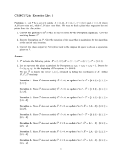
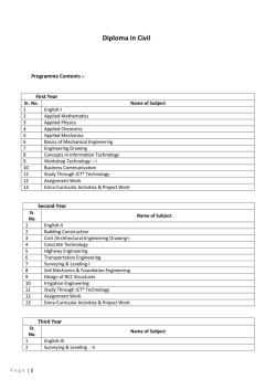
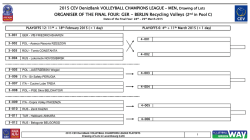
© Copyright 2026