
A valve for every need
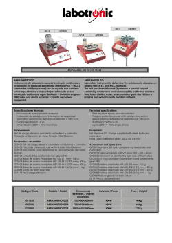
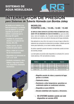
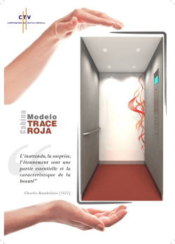
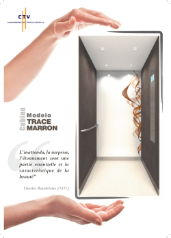
A valve for every need
Catálogo de producto Product Catalogue
ÍNDICE INDEX
La empresa The company
2
Válvulas de bola Ball valves
4
Roscadas Threaded
FIG. 2001 | FIG. 2001 IMF | FIG. 140/141 | FIG. 140/141 IMF
6
Para soldar Welded ends
14
FIG. 142 | FIG. 143 | FIG. 142 IMF | FIG. 143 IMF
Bridas Flanges
22
Válvulas de globo Globe valves
30
Con fuelle With Bellow
32
Sin fuelle Without Bellow
34
Válvulas de compuerta Gate valves
40
42
FIG. 150 HIT | FIG. 154/156 | FIG. 254/256 AIT & 254/256 IIT
FIG. 315/330 AIT & 415/430 IIT
FIG. BGV116/225/216/340
FIG. GV116/GV340 | FIG. G800 A & G800 I
FIG. G150/300 A & G150/300 I
ANSI
FIG. C800 A & C800 I | FIG. C150/300 A & C150/300 I
Válvulas de retención Check valves
46
Pistón Piston
48
Disco Disc
52
Filtros y Accesorios Strainers & Accessories
54
FIG. R800 A & R800 I | FIG. R150/300 A & R150/300 I
FIG. VR316
Filtros Strainers56
Tipo Y Y Type
Cesta Basket Type
Temporales Temporary Type
Separadores centrífugos Steam separator
Accesorios Accessories60
Actuadores neumáticos Pneumatic actuator
Actuadores eléctricos Electric Actuator
Reductores Gear Box
Electroválvulas Solenoid valves
Final de Carrera Limit Switch
A valve for every need
ICP VALVES S.A., fundada en 1968, es una
empresa reconocida mundialmente en
el sector de la válvula industrial gracias a
la experiencia y el saber hacer adquirido
durante todos estos años. ICP VALVES nació
para cubrir las necesidades de un sector del
mercado que demandaba una válvula de
bajo coste con unos excelentes estándares
de calidad.
Disponemos de unos recursos técnicos
y humanos altamente cualificados que
nos permiten ofrecer las soluciones
adecuadas para cada aplicación según las
necesidades de cada cliente, controlando
todo el proceso de diseño y producción
de todos los productos de acuerdo con los
procedimientos de gestión de la calidad
ISO 9001.
Además, somos especialistas en realizar
diseños y/o suministros especiales según
las especificaciones de nuestros clientes,
así como servicios de mantenimiento y
reparación de todo tipo de elementos de
control de fluidos.
Desde nuestros inicios tenemos como
objetivo la total satisfacción de nuestros
clientes que conseguimos gracias al
esfuerzo y la profesionalidad de todo el
equipo de ICP, de nuestros distribuidores
y proveedores.
ICP VALVES S.A., founded in 1968, is a
worldwide-recognized company in the sector
of industrial valve thanks to the experience
and know-how acquired during all these
years. ICP VALVES was born to fill a gap in the
market that was calling for a low cost valve
with an excellent quality.
We count upon highly qualified human
and technical resources, which allow us
to offer the suitable solutions for every
application according to every customer’s
needs, controlling the design and production
process for all products following the ISO
9001 quality management procedure.
Furthermore, we are specialist in designing
specialty products according to customer
specifications, as well as supplying
maintenance or repair services for all kind of
flow control elements.
Since our beginning, our goal is the total
satisfaction of our customers and we
are achieving it with the effort and high
professionalism of our ICP team, our
distributors and suppliers.
Más de 250000 unidades de producto acabado en stock.
More than 250000 units of finished products in our warehouse.
Más de 5000 m² de planta de montaje, pruebas e I+D.
More than 5000 sqm of workshop.
Más de 7000 m² de almacén de producto acabado.
More than 7000 sqm of finish product warehouse.
API 600
600-0016
TP TC 010/2011
TP TC 012/2011
TP TC 032/2013
3
VÁLVULAS DE BOLA
La válvula de bola con asiento flotante es la válvula
de corte por excelencia. El diseño de la válvula de
bola flotante asegura, con la propia presión de la
instalación, una estanqueidad total. El rango del
DN de las válvulas de bola flotante está limitado por
la capacidad de los materiales de los asientos para
soportar la presión, temperatura y peso de la bola.
The floating ball valve is the most common on-off ball
valve. The floating ball valve design assure us, with the
own operation pressure, a total sealing. The DN of the
floating ball valves range is limited by the capability of
the seats material to support the pressure, temperature
and weight of the ball.
5
VÁLVULAS DE BOLA | BALL VALVES
BALL VALVES
VÁLVULAS DE BOLA
ROSCADAS
BALL VALVES
THREADED
FIG. 2001
7
6
8
8
16
9
10
11
4
1
5
3
5
15
2
Partes y materiales
Parts & materials
1
Cuerpo Body
AISI 316
6
Maneta Wrench
AISI 304
11
Junta eje Stem thrust seal
PTFE
2
Lateral Body connector
AISI 316
7
Tuerca maneta Wrench Nut
AISI 304
15
Junta cuerpo lateral Body connector seal
PTFE
3
Bola Ball
AISI 316
8
Arandela maneta Wrench Washer
AISI 304
16
Dispositivo de bloqueo Locking device
AISI 304
4
Eje Stem
AISI 316
9
Prensaestopas Gland
AISI 304
5
Asientos Seat ring
PTFE
10
Estopada Gland packing
PTFE
6
BALL VALVES | THREADED
VÁLVULAS DE BOLA | ROSCADAS
FIG. 2001
Válvulas de Bola Paso Total de 2 piezas, Roscada BSP (DIN 259/2999), 1000 WOG (PN63), desde
1/4” (DN10) a 4” (DN100). Cuerpo en Acero Inoxidable (1.4408). Bola en AISI-316, Asientos en
PTFE. Dispositivo de bloqueo. Las válvulas están certificadas CE y ATEX.
Two pieces Ball Valves, Full Bore, BSP threaded ends (DIN 259/2999), 1000 WOG (PN63), from 1/4”
(DN10) to 4” (DN100). Stainless Steel (1.4408) Body, AISI-316 Ball and PTFE seats. Locking Device. The
valves are certified CE and ATEX.
W
K
φD
H
T
L
Presión - Temperatura Pressure - Temperature
70
PTFE Seats
P (bar)
60
50
1/4” - 1”
40
1 1/4” - 1 1/2”
30
2” - 4”
20
10
0
10
40
90
140
190
240
T (ºC)
Fig. 2001
Size
¼” (DN 10) ⅜” (DN 12)
½” (DN 15)
¾” (DN 20)
1” (DN 25)
1¼” (DN 32)
1½” (DN 40)
2” (DN 50)
2½” (DN 65)
3” (DN 80)
4” (DN 100)
NPS
¼”
⅜”
½”
¾”
1”
1¼”
1½”
2”
2½”
3”
4”
ØD
11,6
12,5
15
20
25
32
38
50
64
76
94
L
50
50
58
65
80
92
105
125
155,6
183
240
W
91
91
103
111
126
154
154
191
244
244
315
K
28,5
28,5
28,5
34,8
34,8
38,1
38,1
38,1
56
56
63
T
12,5
12,5
13
21
22,5
23,5
23,5
23,5
32
35
50
H WeightTorque Kv
48
0,195
4
10,0
48
0,205
4
12,0
52
0,29
5
38,0
61
0,44
8
66,0
65
0,615
10
105,0
79
1,08
14
190,0
83
1,49
25
275,0
97
2,56
30
480,0
129
5,04
36
797,0
138
8,15
60
1210,0
175
18,4
95
1300,0
Dimensiones en mm, peso en kg, par en Nm y Kv en m3/h.
Dimensions in mm, weight in kg, torque in Nm and Kv in m3/h.
7
VÁLVULAS DE BOLA
BALL VALVES
ROSCADAS
THREADED
FIG. 2001 IMF
15
16
14
21
23
10
9
9
7
13
6
22
8
4
19
1
2
5
3
5
Partes y materiales
Parts & materials
1
Cuerpo Body
ASTM A351 CF8M
7
Anillo prensa Gland Ring
AISI 304
15
Maneta Wrench
AISI 304+PVC
2
Lateral Body connector
ASTM A351 CF8M
8
Junta eje Seat thrust seal
PTFE
16
Tuerca Maneta Wrench nut
AISI 304
3
Bola Ball
AISI 316
9
Muelles platillo Belleville washer
AISI 304
19
Junta cuerpo lateral Body connector seal
PTFE
4
Eje Stem
AISI 316
10
Tuerca prensa Gland Nut
AISI 304
21
Arandela Washer
AISI 304
5
Asientos Seat ring
PTFE
13
Tope Stop pin
AISI 304
22
Junta tórica O’ring
FKM
6
Estopada Gland packing
PTFE
14
Dispositivo de bloqueo Locking device
AISI 304
23
Arandela de seguridad Locking washer
AISI 304
8
BALL VALVES | THREADED
VÁLVULAS DE BOLA | ROSCADAS
FIG. 2001 IMF
Válvulas de Bola Paso Total de 2 piezas, Roscada BSP (DIN 259/2999), 1000 WOG (PN63), ISO 5211,
desde 1/4” (DN8) a 4” (DN80). Cuerpo en Acero Inoxidable (1.4408). Bola en AISI-316, Asientos en
PTFE. Dispositivo de bloqueo. Las válvulas están certificadas CE y ATEX.
Two pieces Ball Valves, Full Bore, BSP threaded ends (DIN 259/2999), 1000 WOG (PN63), ISO 5211,
from 1/4” (DN8) to 4” (DN80). Stainless Steel (1.4408) Body, AISI-316 Ball and PTFE seats. Locking
Device. The valves are certified CE and ATEX.
W1
ISO-5211
φd
H
H1
E
φW
D
L
Presión - Temperatura Pressure - Temperature
70
PTFE Seats
P (bar)
60
50
1/4” - 1”
40
1 1/4” - 1 1/2”
30
2” - 4”
20
10
0
10
40
90
140
190
240
T (ºC)
Fig. 2001 IMF
Size
NPS
Ød
L
W1
H1
H
E
D
ØW
ISO 5211 Weight
Torque
Kv
¼” (DN 10)
¼” 11,6
49
140
70
36,5
9
9
12
F04/03
0,325
4
10
⅜” (DN 12) ⅜”
12,5
49
140
70
36,5
9
9
12
F04/03
0,335
4
12
½” (DN 15)
½”
15
58
140
72
37,8
9
9
12
F04/03
0,385
5
38
¾” (DN 20)
¾”
20
65
140
76
42,5
9
9
12
F04/03
0,495
8
66
1” (DN 25)
1”2577160
8445111114
F05/04
0,7710105
1¼” (DN 32) 1¼”
32
90
160
89
51,5
11
11
14
F05/04
1,135
14
190
1½” (DN 40) 1½”
38
98
195
99
59,5
14
14
18
F07/05
1,71
25
275
2” (DN 50)
2” 50
121
195
109
68,5
14
14
18
F07/05
2,705
30
480
2½” (DN 65) 2½”
64
156
350
122
92
17
17
22
F10/07
5,25
36
797
3” (DN 80)
3” 76
183
350
130
106
17
17
22
F10/07
7,575
60
1210
4” (DN 100) 4”
94
240
350
166
116
22
22
28
F12/10
18,635
95
1300
Dimensiones en mm, peso en kg, par en Nm y Kv en m3/h.
Dimensions in mm, weight in kg, torque in Nm and Kv in m3/h.
9
VÁLVULAS DE BOLA
ROSCADAS
BALL VALVES
THREADED
FIG. 140/141
7
6
8
8
16
9
10
10
11
4
13
14
2
5
3
1
5
2
12
Partes y materiales
Parts & materials
1
Cuerpo Body
AISI 316
7
Tuerca maneta Wrench Nut
AISI 304
13
Tuerca Nut
AISI 304
2
Lateral Body connector
AISI 316
8
Arandela maneta Wrench Washer
AISI 304
14
Arandela Washer
AISI 304
3
Bola Ball
AISI 316
9
Prensaestopas Gland
AISI 304
16
Dispositivo de bloqueo Locking device
AISI 304
4
Eje Stem
AISI 316
10
Estopada Gland packing
PTFE
5
Asientos Seat ring
PTFE
11
Junta eje Stem thrust seal
PTFE
6
Maneta Wrench
AISI 304
12
Tornillo Bolt
AISI 304
10
BALL VALVES | THREADED
VÁLVULAS DE BOLA | ROSCADAS
FIG. 140/141
Válvulas de Bola Paso Total de 3 piezas, Roscada BSP (DIN 259/2999) o Roscada NPT (ASME B1.20.1),
1000 WOG (PN63), desde 1/4” (DN10) a 4” (DN100). Cuerpo en Acero Inoxidable (1.4408). Bola en
AISI-316, Asientos en PTFE. Dispositivo de bloqueo. Las válvulas están certificadas CE y ATEX.
Three pieces Ball Valves, Full Bore, BSP threaded ends (DIN 259/2999) or NPT threaded ends (ASME
B1.20.1), 1000 WOG (PN63), from 1/4” (DN10) to 4” (DN100). Stainless Steel (1.4408) Body, AISI-316 Ball
and PTFE seats. Locking Device. The valves are certified CE and ATEX.
BSP
φD
H
W
L
Presión - Temperatura Pressure - Temperature
70
PTFE Seats
P (bar)
60
50
1/4” - 1”
40
1 1/4” - 1 1/2”
30
2” - 4”
20
10
0
10
40
90
140
190
240
T (ºC)
Fig. 140
Size
¼” (DN 10)
⅜” (DN 12)
½” (DN 15)
¾” (DN 20)
1” (DN 25)
1¼” (DN 32)
1½” (DN 40)
2” (DN 50)
2½” (DN 65)
3” (DN 80)
4” (DN 100)
BSP
¼” ⅜”
½”
¾”
1”
1¼”
1½”
2” 2½” 3” 4”
ØD
12
12
15
20
25
32
38
50
64
76
94
L
50
50
60
70
80
93
100
125
158
179
223
W
103
103
103
123
123
153
153
185
243
243
315
H
48
48
52
61
65
79
83
97
135
144
172
Weight
0,31
0,35
0,41
0,7
1,2
2
2,5
3,7
7,4
12,8
23
Torque
5,6
5,6
9
11,3
14,7
19,2
24,9
45,2
73,2
128,8
165,4
Kv
6,6
6,6
11,2
21,0
34,0
57,0
80,0
150,0
265,0
415,0
780,0
NPT
¼” ⅜”
½”
¾”
1”
1¼”
1½”
2” 2½” 3” 4”
ØD
12
12
15
20
25
32
38
50
64
76
94
L
50
50
60
70
80
93
100
125
158
179
223
W
103
103
103
123
123
153
153
185
243
243
315
H
48
48
52
61
65
79
83
97
135
144
172
Weight
0,31
0,35
0,41
0,7
1,2
2
2,5
3,7
7,4
12,8
23
Torque
5,6
5,6
9
11,3
14,7
19,2
24,9
45,2
73,2
128,8
165,4
Kv
6,6
6,6
11,2
21,0
34,0
57,0
80,0
150,0
265,0
415,0
780,0
Fig. 141
Size
¼” (DN 10)
⅜” (DN 12)
½” (DN 15)
¾” (DN 20)
1” (DN 25)
1¼” (DN 32)
1½” (DN 40)
2” (DN 50)
2½” (DN 65)
3” (DN 80)
4” (DN 100)
Dimensiones en mm, peso en kg, par en Nm y Kv en m3/h.
Dimensions in mm, weight in kg, torque in Nm and Kv in m3/h.
11
VÁLVULAS DE BOLA
ROSCADAS
BALL VALVES
THREADED
FIG. 140/141 IMF
15
16
22
21
18
10
9
9
7
6
24
8
17
4
23
14
13
2
5
3
1
5
2
12
Partes y materiales
Parts & materials
1
Cuerpo Body
AISI 316
8
Junta eje Stem thrust seal
PTFE
16
Tuerca Maneta Wrench nut
AISI 304
2
Lateral Body connector
AISI 316
9
Muelles platillo Belleville washer
AISI 304
17
Tornillo tope Stop pin bolt
AISI 304
3
Bola Ball
AISI 316
10
Tuerca prensa Gland Nut
AISI 304
18
Arandela de seguridad Locking washer
AISI 304
4
Eje Stem
AISI 316
12
Tornillo Bolt
AISI 304
21
Arandela Washer
AISI 304
5
Asientos Seat ring
PTFE
13
Arandela Washer
AISI 304
22
Dispositivo de bloqueo Locking device
AISI 304
6
Estopada Gland packing
PTFE
14
Tuerca Nut
AISI 304
23
Tuerca tope Pin stop nut
AISI 304
7
Anillo prensa Gland Ring
AISI 304
15
Maneta Wrench
AISI 304+PVC
24
Junta tórica O’ring
AISI 304
12
BALL VALVES | THREADED
VÁLVULAS DE BOLA | ROSCADAS
FIG. 140/141 IMF
Válvulas de Bola Paso Total de 3 piezas, Roscada BSP (DIN 259/2999) o Roscada NPT (ASME
B1.20.1), 1000 WOG (PN63), ISO 5211, desde 1/4” (DN10) a 4” (DN100). Cuerpo en Acero Inoxidable
(1.4408). Bola en AISI-316, Asientos en PTFE. Dispositivo de bloqueo. Las válvulas están
certificadas CE y ATEX.
Three pieces Ball Valves, Full Bore, BSP threaded ends (DIN 259/2999) or NPT threaded ends (ASME
B1.20.1), 1000 WOG (PN63), ISO 5211, from 1/4” (DN10) to 4” (DN100). Stainless Steel (1.4408) Body,
AISI-316 Ball and PTFE seats. Locking Device. The valves are certified CE and ATEX.
W
ISO-5211
Ød
BSP
H
H1
E
ØW
D
L
Presión - Temperatura Pressure - Temperature
70
PTFE Seats
P (bar)
60
50
1/4” - 1”
40
1 1/4” - 1 1/2”
30
2” - 4”
20
10
0
10
40
90
140
190
240
T (ºC)
Fig. 140 IMF
Size
BSP
Ød
L
W1
H
H1
E
D
ØW
ISO5211 Weight Torque
Kv
¼” (DN 10)
¼” 11,6
55
143
38
65
9
9
12
F04/03
0,58
4,9
6,6
⅜” (DN 12) ⅜”
12,5
60
143
38
65
9
9
12
F04/03
0,58
4,9
6,6
½” (DN 15)
½”
15
75
143
38
65
9
9
12
F04/03
0,57
4,9
11,2
¾” (DN 20)
¾”
20
80
143
47
76
9
9
12
F04/03
0,76
6,5
21,0
1” (DN 25)
1”2590168
6095111114
F05/04
1,03
13,7
34,0
1¼” (DN 32) 1¼”
32
110
168
62,7
95
11
11
14
F05/04
1,59
21,6
57,0
1½” (DN 40) 1½”
38
120
190
79
115
15
14
18
F07/05
2,3
29,5
80,0
2” (DN 50)
2” 50
140
190
88
124
15
14
18
F07/05
3,25
47
150,0
2½” (DN 65) 2½” 64
162
350
109,1
140
17
17
22
F10/07
6,9
58,3
265,0
3” (DN 80)
3” 76
184
350
116,2
150
17
17
22
F10/07
11
86,8
415,0
4” (DN 100) 4”
94
228
350
142
175
22
22
28
F12/07
19,2
122,6
780,0
Fig. 141 IMF
Size
NPT
Ød
L
W1
H
H1
E
D
ØW
ISO5211 Weight Torque
Kv
¼” (DN 10)
¼” 11,6
55
143
38
65
9
9
12
F04/03
0,58
4,9
6,6
⅜” (DN 12) ⅜”
12,5
60
143
38
65
9
9
12
F04/03
0,58
4,9
6,6
½” (DN 15)
½”
15
75
143
38
65
9
9
12
F04/03
0,57
4,9
11,2
¾” (DN 20)
¾”
20
80
143
47
76
9
9
12
F04/03
0,76
6,5
21,0
1” (DN 25)
1”2590168
6095111114
F05/04
1,03
13,7
34,0
1¼” (DN 32) 1¼”
32
110
168
62,7
95
11
11
14
F05/04
1,59
21,6
57,0
1½” (DN 40) 1½”
38
120
190
79
115
15
14
18
F07/05
2,3
29,5
80,0
2” (DN 50)
2” 50
140
190
88
124
15
14
18
F07/05
3,25
47
150,0
2½” (DN 65) 2½” 64
162
350
109,1
140
17
17
22
F10/07
6,9
58,3
265,0
3” (DN 80)
3” 76
184
350
116,2
150
17
17
22
F10/07
11
86,8
415,0
4” (DN 100) 4”
94
228
350
142
175
22
22
28
F12/07
19,2
122,6
780,0
Dimensiones en mm, peso en kg, par en Nm y Kv en m3/h.
Dimensions in mm, weight in kg, torque in Nm and Kv in m3/h.
13
VÁLVULAS DE BOLA
PARA SOLDAR
FIG. 142
BALL VALVES
WELDED ENDS
7
6
8
8
16
9
10
10
11
4
13
14
2
5
3
1
5
2
12
Partes y materiales
Parts & materials
1
Cuerpo Body
AISI 316
7
Tuerca maneta Wrench Nut
AISI 304
13
Tuerca Nut
AISI 304
2
Lateral Body connector
AISI 316
8
Arandela maneta Wrench Washer
AISI 304
14
Arandela Washer
AISI 304
3
Bola Ball
AISI 316
9
Prensaestopas Gland
AISI 304
16
Dispositivo de bloqueo Locking device
AISI 304
4
Eje Stem
AISI 316
10
Estopada Gland packing
PTFE
5
Asientos Seat ring
PTFE
11
Junta eje Stem thrust seal
PTFE
6
Maneta Wrench
AISI 304
12
Tornillo Bolt
AISI 304
14
BALL VALVES | WELDED ENDS
VÁLVULAS DE BOLA | PARA SOLDAR
FIG. 142
Válvulas de Bola Paso Total de 3 piezas, para Soldar SW (ASME B16.11 & DIN 3239 part 2),
1000 WOG (PN63), desde 1/4” (DN10) a 4” (DN100). Cuerpo en Acero Inoxidable (1.4408). Bola en
AISI-316, Asientos en PTFE. Dispositivo de bloqueo. Las válvulas están certificadas CE y ATEX.
Three pieces Ball Valves, Full Bore, SW ends (ASME B16.11 & DIN 3239 part 2), 1000 WOG (PN63), from
1/4” (DN10) to 4” (DN100). Stainless Steel (1.4408) Body, AISI-316 Ball and PTFE seats. Locking Device.
The valves are certified CE and ATEX.
ØD1
φD
H
W
L
Presión - Temperatura Pressure - Temperature
70
PTFE Seats
P (bar)
60
50
1/4” - 1”
40
1 1/4” - 1 1/2”
30
2” - 4”
20
10
0
10
40
90
140
190
240
T (ºC)
Fig. 142
Size
¼” (DN 10)
⅜” (DN 12)
½” (DN 15)
¾” (DN 20)
1” (DN 25)
1¼” (DN 32)
1½” (DN 40)
2” (DN 50)
2½” (DN 65)
3” (DN 80)
4” (DN 100)
ØD
12
12
15
20
25
32
38
50
64
76
94
ØD1
14,1
17,6
21,7
27,1
33,9
42,6
48,7
61,1
77
89,8
115,5
L
50
50
60
70
80
93
100
125
158
179
223
W
103
103
103
123
123
153
153
185
243
243
315
H
48
48
52
61
65
79
83
97
135
144
172
Weight
0,31
0,35
0,41
0,7
1,2
2
2,5
3,7
7,4
12,8
23
Torque
5,6
5,6
9
11,3
14,7
19,2
24,9
45,2
73,2
128,8
165,4
Kv
6,6
6,6
11,2
21,0
34,0
57,0
80,0
150,0
265,0
415,0
780,0
Dimensiones en mm, peso en kg, par en Nm y Kv en m3/h.
Dimensions in mm, weight in kg, torque in Nm and Kv in m3/h.
15
VÁLVULAS DE BOLA
BALL VALVES
PARA SOLDAR
WELDED ENDS
FIG. 143
7
8
6
8
16
9
10
10
11
4
13
14
2
5
3
1
5
2
12
Partes y materiales
Parts & materials
1
Cuerpo Body
AISI 316
7
Tuerca maneta Wrench Nut
AISI 304
13
Tuerca Nut
AISI 304
2
Lateral Body connector
AISI 316
8
Arandela maneta Wrench Washer
AISI 304
14
Arandela Washer
AISI 304
3
Bola Ball
AISI 316
9
Prensaestopas Gland
AISI 304
16
Dispositivo de bloqueo Locking device
AISI 304
4
Eje Stem
AISI 316
10
Estopada Gland packing
PTFE
5
Asientos Seat ring
PTFE
11
Junta eje Stem thrust seal
PTFE
6
Maneta Wrench
AISI 304
12
Tornillo Bolt
AISI 304
16
BALL VALVES | WELDED ENDS
VÁLVULAS DE BOLA | PARA SOLDAR
FIG. 143
Válvulas de Bola Paso Total de 3 piezas, para Soldar BW (ASME B16.25 & DIN 3239 part 1),
1000 WOG (PN63), desde 1/4” (DN10) a 4” (DN100). Cuerpo en Acero Inoxidable (1.4408). Bola en
AISI-316, Asientos en PTFE. Dispositivo de bloqueo. Las válvulas están certificadas CE y ATEX.
Three pieces Ball Valves, Full Bore, BW ends (ASME B16.25 & DIN 3239 part 1), 1000 WOG (PN63), from
1/4” (DN10) to 4” (DN100). Stainless Steel (1.4408) Body, AISI-316 Ball and PTFE seats. Locking Device.
The valves are certified CE and ATEX.
W
ØA
φD
H
37.5°
L1
Presión - Temperatura Pressure - Temperature
70
PTFE Seats
P (bar)
60
50
1/4” - 1”
40
1 1/4” - 1 1/2”
30
2” - 4”
20
10
0
10
40
90
140
190
240
T (ºC)
Fig. 143
Size
¼” (DN 10)
⅜” (DN 12)
½” (DN 15)
¾” (DN 20)
1” (DN 25)
1¼” (DN 32)
1½” (DN 40)
2” (DN 50)
2½” (DN 65)
3” (DN 80)
4” (DN 100)
ØA
18
19,5
23
28,8
34,8
45
51
62,5
77
94
116
ØD
12
12
15
20
25
32
38
50
64
76
94
L1
60,4
60,4
66,5
80
84
104
112
132
165
182,2
226,8
W
103
103
103
123
123
153
153
185
243
243
315
H
48
48
52
61
65
79
83
97
135
144
172
Weight
0,31
0,35
0,41
0,7
1,2
2
2,5
3,7
7,4
12,8
23
Torque
5,6
5,6
9
11,3
14,7
19,2
24,9
45,2
73,2
128,8
165,4
Kv
6,6
6,6
11,2
21,0
34,0
57,0
80,0
150,0
265,0
415,0
780,0
Dimensiones en mm, peso en kg, par en Nm y Kv en m3/h.
Dimensions in mm, weight in kg, torque in Nm and Kv in m3/h.
17
VÁLVULAS DE BOLA
BALL VALVES
PARA SOLDAR
WELDED ENDS
FIG. 142 IMF
15
16
22
21
18
10
9
9
7
6
24
8
17
4
23
14
13
2
5
3
1
5
2
12
Partes y materiales
Parts & materials
1
Cuerpo Body
AISI 316
8
Junta eje Seat thrust seal
PTFE
16
Tuerca Maneta Wrench nut
AISI 304
2
Lateral Body connector
AISI 316
9
Muelles platillo Belleville washer
AISI 304
17
Tuerca tope Stop pin
AISI 304
3
Bola Ball
AISI 316
10
Tuerca prensa Gland Nut
AISI 304
18
Arandela de seguridad Locking washer
AISI 304
4
Eje Stem
AISI 316
12
Tornillo Bolt
AISI 304
21
Arandela Washer
AISI 304
5
Asientos Seat ring
PTFE
13
Arandela Washer
AISI 304
22
Dispositivo de bloqueo Locking device
AISI 304
6
Estopada Gland packing
PTFE
14
Tuerca Nut
AISI 304
23
Arandela Pin stop nut
AISI 304
7
Anillo prensa Gland Ring
AISI 304
15
Maneta Wrench
AISI 304+PVC
24
Junta tórica O’ring
AISI 304
18
BALL VALVES | WELDED ENDS
VÁLVULAS DE BOLA | PARA SOLDAR
FIG. 142 IMF
Válvulas de Bola Paso Total de 3 piezas, para Soldar SW (ASME B16.11 & DIN 3239 part 2),
1000 WOG (PN63), ISO 5211, desde 1/4” (DN10) a 4” (DN100). Cuerpo en Acero Inoxidable (1.4408).
Bola en AISI-316, Asientos en PTFE. Dispositivo de bloqueo.
Las válvulas están certificadas CE y ATEX.
Three pieces Ball Valves, Full Bore, SW ends (ASME B16.11 & DIN 3239 part 2), 1000 WOG (PN63), ISO
5211, from 1/4” (DN10) to 4” (DN100). Stainless Steel (1.4408) Body, AISI-316 Ball and PTFE seats.
Locking Device. The valves are certified CE and ATEX.
W1
ISO-5211
Ød
Ød1
H
H1
E
ØW
D
L
Presión - Temperatura Pressure - Temperature
70
PTFE Seats
P (bar)
60
50
1/4” - 1”
40
1 1/4” - 1 1/2”
30
2” - 4”
20
10
0
10
40
90
140
190
240
T (ºC)
Fig. 142 IMF
Size
Ød
Ød1
L
W1
H
H1
E
D
ISO 5211
Weight
Torque
Kv
¼” (DN 10)
11,5
14,2
55
143
38
65
9
9
F04/03
0,59
4,9
6,6
⅜” (DN 12)
12,5
17,7
60
143
38
65
9
9
F04/03
0,58
4,9
6,6
½” (DN 15)
15
21,8
75
143
38
65
9
9
F04/03
0,57
4,9
11,2
¾” (DN 20)
20
27,2
80
143
47
76
9
9
F04/03
0,71
6,5
21,0
1” (DN 25)
25349016860
951111
F05/04
1,03
13,7
34,0
1¼” (DN 32)
32
42,7
110
168
62,7
95
11
11
F05/04
1,56
21,6
57,0
1½” (DN 40)
38
48,8
120
190
79
115
15
14
F07/05
2,5
29,5
80,0
2” (DN 50)
50
61,2
140
190
88
124
15
14
F07/05
3,44
47
150,0
2½” (DN 65)
65
74
162
350
109,1
140
17
17
F10/07
6,4
58,3
265,0
3” (DN 80)
80
90
184
350
116,2
150
17
17
F10/07
11,2
86,8
415,0
4” (DN 100)
100
115,6
228
350
142
175
22
22
F12/07
22
122,6
780,0
Dimensiones en mm, peso en kg, par en Nm y Kv en m3/h.
Dimensions in mm, weight in kg, torque in Nm and Kv in m3/h.
19
VÁLVULAS DE BOLA
BALL VALVES
PARA SOLDAR
WELDED ENDS
FIG. 143 IMF
15
16
22
21
18
10
9
9
7
6
24
8
17
4
23
14
13
2
5
3
1
5
2
12
Partes y materiales
Parts & materials
1
Cuerpo Body
AISI 316
8
Junta eje Seat thrust seal
PTFE
16
Tuerca maneta Wrench nut
AISI 304
2
Lateral Body connector
AISI 316
9
Muelles platillo Belleville washer
AISI 304
17
Tope Stop pin
AISI 304
3
Bola Ball
AISI 316
10
Tuerca prensa Gland Nut
AISI 304
18
Arandela de seguridad Locking washer
AISI 304
4
Eje Stem
AISI 316
12
Tornillo Bolt
AISI 304
21
Arandela Washer
AISI 304
5
Asientos Seat ring
PTFE
13
Arandela Washer
AISI 304
22
Dispositivo de bloqueo Locking device
AISI 304
6
Estopada Gland packing
PTFE
14
Tuerca Nut
AISI 304
23
Tuerca tope Pin stop nut
AISI 304
7
Anillo prensa Gland Ring
AISI 304
15
Maneta Wrench
AISI 304+PVC
24
Junta tórica O’ring
AISI 304
20
BALL VALVES | WELDED ENDS
VÁLVULAS DE BOLA | PARA SOLDAR
FIG. 143 IMF
Válvulas de Bola Paso Total de 3 piezas, para Soldar BW (ASME B16.25 & DIN 3239 part 1),
1000 WOG (PN63), ISO 5211, desde 1/4” (DN10) a 4” (DN100). Cuerpo en Acero Inoxidable (1.4408).
Bola en AISI-316, Asientos en PTFE. Dispositivo de bloqueo.
Las válvulas están certificadas CE y ATEX.
Three pieces Ball Valves, Full Bore, BW ends (ASME B16.25 & DIN 3239 part 1), 1000 WOG (PN63), ISO
5211, from 1/4” (DN10) to 4” (DN100). Stainless Steel (1.4408) Body, AISI-316 Ball and PTFE seats.
Locking Device. The valves are certified CE and ATEX.
W1
H
E
ØW
ISO-5211
Ød
H1
37.5°
D
L
Presión - Temperatura Pressure - Temperature
70
PTFE Seats
P (bar)
60
50
1/4” - 1”
40
1 1/4” - 1 1/2”
30
2” - 4”
20
10
0
10
40
90
140
190
240
T (ºC)
Fig. 143 IMF
Size
Ød
L1
W1
H1
H
E
D
ISO 5211
Weight
Torque
Kv
¼” (DN 10)
11,6
60
143
65
38
9
9
F04/03
0,59
4,9
6,6
⅜” (DN 12)
12,5
60
143
65
38
9
9
F04/03
0,58
4,9
6,6
½” (DN 15)
15
70
143
65
38
9
9
F04/03
0,57
4,9
11,2
¾” (DN 20)
20
85
143
76
47
9
9
F04/03
0,71
6,5
21,0
1” (DN 25)
25951689560 1111
F05/04
1,03
13,7
34,0
1¼” (DN 32)
32
110
168
95
62,7
11
11
F05/04
1,56
21,6
57,0
1½” (DN 40)
38
120
190
115
79
15
14
F07/05
2,5
29,5
80,0
2” (DN 50)
50
142
190
124
88
15
14
F07/05
3,44
47
150,0
2½” (DN 65)
64
166
350
140
109,1
17
17
F10/07
6,4
58,3
265,0
3” (DN 80)
76
182
350
150
116,2
17
17
F10/07
11,2
86,8
415,0
4” (DN 100)
94
227
350
175
142
22
22
F12/07
22
122,6
780,0
Dimensiones en mm, peso en kg, par en Nm y Kv en m3/h.
Dimensions in mm, weight in kg, torque in Nm and Kv in m3/h.
21
VÁLVULAS DE BOLA
BRIDAS
BALL VALVES
FLANGES
FIG. 150 HIT
6
16
17
471
72
72
912
12
4
15
2
13
5
3
5
1
Partes y materiales
Parts & materials
1
Cuerpo Body
EN-GJL-250
2
Lateral Body connector
EN-GJL-250
3
Bola Ball
DN 15 to 25: AISI 303
DN 32 to 200: AISI 304
4
Eje Stem
AISI 304
5
Asiento Seat ring
PTFE
6
Maneta Wrench
Carbon steel
17
Arandela Washer
Zinc plated carbon steel
12
Junta eje Stem thrust seal
PTFE
72
Junta tórica “0” Ring
FKM
13
Junta cuerpo lateral Body connector seal
PTFE
471
Arandela Washer
DIN 471Carbon St.
15
Tornillo Bolt
DIN 933 5.6
912
Tornillo tope Stop pin bolt
DIN 912 8.8
16
Tornillo Bolt
DIN 933 5.6
22
BALL VALVES | FLANGES
VÁLVULAS DE BOLA | BRIDAS
FIG. 150 HIT
Válvulas de Bola Paso Total de 2 piezas, Bridas PN16, desde DN15 a DN200. Cuerpo en Fundición
de Hierro EN-GJL250 (GG25). Bola en AISI-304, Asientos en PTFE. Distancia entre caras (face to
face) según EN 558-1 SERIE 27 (DIN 3202 F18). Bridas según EN 1092-2 (DIN 2501). Las válvulas
están certificadas CE y ATEX.
Two pieces Ball Valves, Full Bore, Flanges PN16, from DN15 to DN200. Cast iron GJL250 (GG25) Body,
AISI-304 Ball and PTFE seats. Face-to-face according EN 558-1 SERIE 27 (DIN 3202 F18). Flanges
according EN 1092-2 (DIN 2501). The valves are certified CE and ATEX.
M
C
J
ØP
ØT
ØR
Ball only DN 32 to 200
4x900=360°
Ball only DN 15 to 25
Ø5
-0.05
H
B
n x ØS
ØA
ØI
L1
L
P (bar)
Presión - Temperatura Pressure - Temperature
18
16
14
12
10
8
6
* Depending on FKM
4
resistance to the fluid.
2
0
-10
50
120
150
180
T (ºC)
200
Fig. 150 HIT
DN
ØP
L
L1
ØR
n x ØS
ØT
M
H ISO 5211 ØA
B
C
ØI
J
Weight Torque Kv
15 13115 49 654x149517092F04 19 7,55,5 10 72,12637,4
20 1712055,5754x1410517095,5F04 19 6 5 10 72,72674,8
25 24 12551,585 4x14115170102,2F04 21 6,2 5 10 7 3,6211 105
32 31 130 531004x18140170114,7
F04 21 6,7 5,5 10 7 5,3212176
40 3814061110
4x18
150
302,5
119
F0430151616 126,926223
50 5015062125
4x18
165
302,5
127
F0430151616 12 9 41416
185
224141
F0735181918 13
11,68
41660
65
65
170
81,5 145 4x18 (**)
80 8018079160
8x18
200
335
151,5
F0735181918 13
14,68
71
1200
10010019094180
8x18
220
350
176,5
F0738192022 16
20,23
119
1980
125 125 325 120,5210 8x18 250 350 208 F07 38 19,5 20 22 16 33,73190 3600
150 150 350 1552408x22285500254,5F10 50 24,5 27 28 2049,772205040
200 200 400 19029512x22340500293,5F10 50 24,5 27 28 2081,7745010890
Dimensiones en mm, peso en kg, par en Nm y Kv en m3/h.
(**) Según norma UNE-EN 1092-2 podemos suministrar con 8 taladros a petición del cliente.
Dimensions in mm, weight in kg, torque in Nm and Kv in m3/h.
(**) According to UNE-EN 1092-2 we can supply with 8 holes under client demand.
23
VÁLVULAS DE BOLA
BRIDAS
BALL VALVES
FLANGES
FIG. 154/156
6
16
66
20
7
10
11
18
72
12
4
15
2
13
52
5
3
5
1
Partes y materiales
Parts & materials
1
2
3
4
5
6
Cuerpo Body
AIT: 1.0619
IIT: 1.4408
Lateral Body connector
AIT: 1.0619
IIT: 1.4408
Bola Ball
AIT: A 351 Gr. CF8M / A 479 Tp.316
IIT: A 351 Gr. CF8M / A 479 Tp.316
Eje Stem
AIT: A 479 Tp.316
IIT: A 479 Tp.316
Asiento Seat ring
AIT: PTFE
IIT: PTFE
Maneta Wrench
AIT: AISI 304
IIT: AISI 304
7
10
11
12
13
15
Tuerca prensa Gland nut
AIT: A2
IIT: A2
Anillo prensa Gland ring
AIT: AISI 304
IIT: AISI 304
Estopada Gland packing
AIT: PTFE
IIT: PTFE
Stem thrust seal Stem thrust seal
AIT: PTFE + 25% GF
IIT: PTFE + 25% GF
Junta eje Body connector seal
AIT: PTFE
IIT: PTFE
Tornillo Bolt
AIT: 8.8
IIT: A2
24
16
18
20
52
66
72
Tuerca maneta Wrench nut
AIT: A2
IIT: A2
Tope Stop pin
AIT: AISI 304
IIT: AISI 304
Arandela espaciadora Spacer
AIT: AISI 304
IIT: AISI 304
Junta tórica “O” ring
AIT: FKM
IIT: FKM
Dispositivo de bloqueo Locking device
AIT: AISI 304
IIT: AISI 304
Junta tórica “O” ring
AIT: FKM
IIT: FKM
BALL VALVES | FLANGES
VÁLVULAS DE BOLA | BRIDAS
FIG. 154/156
Válvulas de Bola Paso Total de 2 piezas, Bridas PN40 (desde DN15 a DN50) y PN16 (desde DN65
a DN200). Cuerpo en Acero Inoxidable (1.4408). Bola en AISI-316, Asientos en PTFE. Dispositivo
Antiestático. Dispositivo de bloqueo. ISO 5211 y eje cuadrado para montaje directo de
actuadores. Distancia entre caras (face to face) según EN 558-1 SERIE 27 (DIN 3202 F18). Bridas
según EN 1092-1. Las válvulas están certificadas CE y ATEX.
Two pieces Ball Valves, Full Bore, Flanges PN40 (from DN15 to DN65) and PN16 (from DN50 to DN200).
Stainless Steel (1.4408) Body, AISI-316 Ball and PTFE seats. Antistatic Device. Locking Device. ISO 5211
connection and square stem to direct mounting of actuators. Face-to-face according with EN 558-1
SERIE 27 (DIN 3202 F18). Flanges according EN 1092-1. The valves are certified CE and ATEX.
H
n x ØS
M
B
C
ØI
4x900=360°
J
-0
.0
5
ØP
ØT
ØR
Ø5
L1
L
P (bar)
Presión - Temperatura Pressure - Temperature
45
40
35
30
25
20
15
10
5
0
-20
PTFE Seats
DN 15 to 100
DN 125 to 200
For 1.4408 only.
For other material
consult EN 1092-1
30
80
130
180
T (ºC)
230
Fig. 154 PN40
DN
15
20
25
32
40
50
ØP
13
17
24
31
38
50
L
115
120
125
130
140
150
L1
48
52
46
47
54
60
ØR
65
75
85
100
110
125
n x ØS
4 x 14
4 x 14
4 x 14
4 x 18
4 x 18
4 x 18
ØT
95
105
115
140
150
165
H
78
82
88
100
118
125
M
171
171
171
171
301
301
ISO 5211
F 05
F 05
F 05
F 05
F 07
F 07
B
11
11,5
13,2
13,2
19,5
19,5
C
10,5
11
14
14
20,5
20,5
I
M10x1,5
M10x1,5
M12x1,5
M12x1,5
M18x1,5
M18x1,5
J
8
8
9
9
14
14
Weight
2
3
4
6
7
10
Torque
8
12
14
22
27
50
Kv
20
40
75
130
170
270
L
170
180
190
325
350
400
L1
69
68
83
120,5
145
180
ØR
145
160
180
210
240
295
n x ØS
4 x 18
8 x 18
8 x 18
8 x 18
8 x 22
12 x 22
ØT
185
200
220
250
285
340
H
137
148
165
192
217
265
M
336
336
336
336
500
500
ISO 5211 B
F 07
20
F07
20
F 10
23,5
F10
24,5
F10
28,5
F12
34
C
21
21
24,5
25,5
29,5
31
I
M22x1,5
M22x1,5
M22x1,5
M25x1,5
M28x1,5
M35x2
J
17
17
17
17
22
27
Weight
13
17
26
43
61
111
Torque
41
71
119
190
220
450
Kv
550
1000
1650
3000
4200
9000
Fig. 156 PN16
DN
65
80
100
125
150
200
ØP
65
80
100
125
150
200
Dimensiones en mm, peso en kg, par en Nm y Kv en m3/h.
Dimensions in mm, weight in kg, torque in Nm and Kv in m3/h.
25
VÁLVULAS DE BOLA
BRIDAS
BALL VALVES
FLANGES
FIG. 254/256 AIT
FIG. 254/256 IIT
14
12.1
12
10
10
13
9
8
7
18
6
5
16
15
2
17
4
3
4
1
Partes y materiales
Parts & materials
1
2
3
4
5
6
Cuerpo Body
AIT: 1.0619
IIT: 1.4408
Lateral Body connector
AIT: 1.0619
IIT: 1.4408
Bola Ball
AIT: A 351 Gr. CF8M (DN-15 ~ 25 A 479 Tp.316)
IIT: A 351 Gr. CF8M (DN-15 ~ 25 A 479 Tp.316)
Asiento Seat ring
AIT: PTFE
IIT: PTFE
Eje Stem
AIT: A 479 Tp.316
IIT: A 479 Tp.316
Junta eje Stem thrust seal
AIT: 25% G.F. PTFE
IIT: 25% G.F. PTFE
7
8
9
10
12
12.1
Junta tórica “O” Ring
AIT: FKM
IIT: FKM
Estopada Gland packing
AIT: Graphite
IIT: Graphite
Prensaestopas Gland
AIT: AISI 303
IIT: AISI 303
Muelles platillo Belleville washer
AIT: Inconel - 718
IIT: Inconel - 718
Tuerca prensa Gland nut
AIT: AISI 303
IIT: AISI 303
Tuerca Nut
AIT: AISI 303
IIT: AISI 303
26
13
14
15
16
17
18
Arandela de seguridad Locking washer
AIT: 25% G.F. PTFE
IIT: 25% G.F. PTFE
Maneta Wrench
AIT: A 216 Gr. WCB
IIT: A 216 Gr. WCB
Esparrago Stud
AIT: A 193 Gr. B7M
IIT: A 193 Gr. B8M
Tuerca Nut
AIT: A 194 Gr. 2HM
IIT: A 194 Gr. 8M
Junta Espirometálica Spiralwound gasket
AIT: AISI 316L + PTFE + Graphite
IIT: AISI 316L + PTFE + Graphite
Tornillo Bolt
AIT: A2
IIT: A2
BALL VALVES | FLANGES
VÁLVULAS DE BOLA | BRIDAS
FIG. 254/256 AIT & 254/256 IIT
H
Válvulas de Bola Paso Total de 2 piezas, Bridas PN40 y PN16, desde DN15 a DN200. Cuerpo en Acero
Inoxidable (1.4408) o Acero al Carbono (1.0619). Bola en AISI-316, Asientos en PTFE modificado.
Dispositivo Antiestático. Dispositivo de bloqueo. Eje diseñado según norma EN 15081. Distancia
entre caras (face to face) según EN 558-1 SERIE 27 (DIN 3202 F18). Las válvulas están certificadas
CE, ATEX, FIRE SAFE (según ISO 10497:2004) and FUGITIVE EMISSION (según ISO 15848-1:2006).
Two pieces Ball Valves, Full Bore, Flanges PN40 and PN16, from DN15 to DN200. Stainless Steel
(1.4408) and Carbon Steel (1.0619) Body, AISI-316 Ball and Modified PTFE seats. Antistatic Device.
Locking Device. Stem is according EN 15081. Face-to-face according with EN 558-1 SERIE 27 (DIN 3202
F18). The valves are certified CE, ATEX, FIRE SAFE (according ISO 10497:2004) and FUGITIVE EMISSION
(according ISO 15848-1:2006).
M
B
H
n x ØS
C
I
4x900=360°
ØP
J
-0.05
ØR
ØT
Ø5
L1
L
45
40
35
30
25
20
15
10
5
0
-20
Presión - Temperatura Pressure - Temperature
PTFE Seats
FIG. 256
P (bar)
P (bar)
Presión - Temperatura Pressure - Temperature
FIG. 254
For 1.0619 only.
For other material
consult EN 1092-1
30
80
130
180
230
T (ºC)
45
40
35
30
25
20
15
10
5
0
-50
0
PTFE Seats
FIG. 256
FIG. 254
For 1.4408 only.
For other material
consult EN 1092-1
50
100
150
200
250
T (ºC)
Fig. 254 PN40
DN
15
20
25
32
40
50
65
80
100
125
150
ØP
15
20
25
32
40
50
65
78
100
125
151
L
115
120
125
130
140
150
170
180
190
325
350
L1
53
52
52
54
55
61
72
73
83
120
135
ØR
65
75
85
100
110
125
145
160
190
220
250
n x ØS
4 x 14
4 x 14
4 x 14
4 x 18
4 x 18
4 x 18
8 x 18
8 x 18
8 x 22
8 x 26
8 x 26
ØT ISO 5211
95
F 05
105
F 05
115
F 05
140
F 05
150
F 07
165
F 07
185
F 07
200
F 10
235
F 10
270
F 12
300
F 12
B
18
18
22
22
33
33
34
34
45
56
56
C
11
11
21
21
32
32
33
33
43,5
54,5
54,5
I
M10
M10
M12
M12
M18
M18
M22
M22
M28
M36
M36
J
7
7
8
8
12
12
15
15
19
24
24
H
68
70
86
89,5
122,5
127,5
140
190
192,5
240
259
M
170
170
170
170
215
215
350
450
466
775
775
Weight
2,4
3,2
4,1
5,8
8,1
10,6
14,8
20,6
29,2
53,6
74,7
Torque
8
12
14
22
27
50
74
118
136
204
408
Kv
20
40
75
130
170
270
550
1000
1650
3000
4200
L
170
180
190
325
350
400
L1
72
73
83
120
135
200
ØR
145
160
180
210
240
295
n x ØS
4 x 18
8 x 18
8 x 18
8 x 18
8 x 22
12 x 22
ØT ISO 5211
185
F 07
200
F 10
220
F 10
250
F 12
285
F 12
340
F 14
B
34
34
45
56
56
69
C
33
33
43,5
54,5
54,5
67
I
M22
M22
M28
M36
M36
M48
J
15
15
19
24
24
32
H
140
190
192,5
240
259
319
M
350
450
466
775
775
845
Weight
13,3
19,1
25,6
47,6
63,5
115,3
Torque
51
77
116
159
215
493
Kv
550
1000
1650
3000
4200
9000
Fig. 256 PN16
DN
65
80
100
125
150
200
ØP
65
78
100
125
151
203
Dimensiones en mm, peso en kg, par en Nm y Kv en m3/h.
Dimensions in mm, weight in kg, torque in Nm and Kv in m3/h.
27
VÁLVULAS DE BOLA
BRIDAS
BALL VALVES
FLANGES
FIG. 315/330 AIT
FIG. 415/430 IIT
14
12.1
12
10
10
13
9
8
7
18
6
5
16
15
2
17
4
3
4
1
Partes y materiales
Parts & materials
1
2
3
4
5
6
Cuerpo Body
AIT: A 216 Gr. WCB (C ≤ 0,25)
IIT: A 351 Gr. CF8M
Lateral Body connector
AIT: A 216 Gr. WCB (C ≤ 0,25)
IIT: A 351 Gr. CF8M
Bola Ball
AIT: A 351 Gr. CF8M (DN-15 ~ 25 A 479 Tp.316)
IIT: A 351 Gr. CF8M (DN-15 ~ 25 A 479 Tp.316)
Asiento Seat ring
AIT: PTFE
IIT: PTFE
Eje Stem
AIT: A 479 Tp.316
IIT: A 479 Tp.316
Junta eje Stem thrust seal
AIT: 25% G.F. PTFE
IIT: 25% G.F. PTFE
7
8
9
10
12
12.1
Junta tórica “O” Ring
AIT: FKM
IIT: FKM
Estopada Gland packing
AIT: Graphite
IIT: Graphite
Prensaestopas Gland
AIT: AISI 303
IIT: AISI 303
Muelles platillo Belleville washer
AIT: Inconel - 718
IIT: Inconel - 718
Tuerca prensa Gland nut
AIT: AISI 303
IIT: AISI 303
Tuerca Nut
AIT: AISI 303
IIT: AISI 303
28
13
14
15
16
17
18
Arandela de seguridad Locking washer
AIT: 25% G.F. PTFE
IIT: 25% G.F. PTFE
Maneta Wrench
AIT: A 216 Gr. WCB
IIT: A 216 Gr. WCB
Esparrago Stud
AIT: A 193 Gr. B7M
IIT: A 193 Gr. B8M
Tuerca Nut
AIT: A 194 Gr. 2HM
IIT: A 194 Gr. 8M
Junta Espirometálica Spiralwound gasket
AIT: AISI 316L + PTFE + Graphite
IIT: AISI 316L + PTFE + Graphite
Tornillo Bolt
AIT: A2
IIT: A2
BALL VALVES | FLANGES
VÁLVULAS DE BOLA | BRIDAS
FIG. 315/330 AIT & FIG. 415/430 IIT
H
Válvulas de Bola Paso Total de 2 piezas, Bridas 150lbs y 300lbs, desde 1/2” a 8”. Cuerpo en Acero
Inoxidable (A351 Gr. CF8M) o Acero al Carbono (A216 Gr. WCB). Bola en AISI-316, asientos en PTFE
Modificado. Dispositivo Antiestático. Dispositivo de bloqueo. Eje diseñado según la norma EN
15081. Diseño válvulas conforme NACE MR01.75. Distancia entre caras (face to face) según ASME
B16.10 Long Pattern. Las válvulas están certificadas CE, ATEX, FIRE SAFE (según ISO 10497:2004)
and FUGITIVE EMISSION (según ISO 15848-1:2006).
Two pieces Ball Valves, Full Bore, Flanges class 150 and class 300, from 1/2” to 8”.
Stainless Steel (A351 Gr. CF8M) and Carbon Steel (A216 Gr. WCB) Body, AISI-316 Ball and Modified
PTFE seats. Antistatic Device. Locking Device. Stem is according EN 15081. Valves are according with
NACE MR01.75. Face-to-face according with ASME B16.10 Long Pattern. The valves are certified CE,
ATEX, FIRE SAFE (according ISO 10497:2004) and FUGITIVE EMISSION (according ISO 15848-1:2006).
M
B
H
n x ØS
C
I
4x900=360°
ØP
J
-0.05
ØR
ØT
Ø5
L1
L
Presión - Temperatura Pressure - Temperature
Presión - Temperatura Pressure - Temperature
60
P (bar)
P (bar)
PN 50 (Class 300)
30
For A216 Gr. WCB only.
For other materials
consult ASME B16.34
20
10
1
31
61
91 121 151 181 211 241 271
PTFE Seats
50
PN 20 (Class 150)
40
0
-29
60
PTFE Seats
50
PN 20 (Class 150)
40
PN 50 (Class 300)
30
For A351 Gr. CF8M only.
For other materials
consult ASME B16.34
20
10
T (ºC)
0
-50
-5
40
85
130
175
220
265
T (ºC)
Fig. 315/415 150Lbs Class 150
Size
½”
¾”
1”
1½”
2”
2½”
3”
4”
6”
8”
ØP
15
20
25
40
50
65
78
100
151
203
L
108
117
127
165
178
190
203
229
394
457
L1
47
50
52
65
61
75
78,5
90
174
209
ØR
60,45
69,8
79,24
98,55
120,65
139,7
152,4
190,5
241,3
298,45
n x ØS
4 x 15,74
4 x 15,74
4 x 15,74
4 x 15,74
4 x 19
4 x 19
4 x 19
8 x 19
8 x 22,2
8 x 22,2
ØT ISO 5211
88,9
F 05
98,5
F 05
108
F 05
127
F 07
152
F 07
178
F 07
191
F 10
229
F 10
279,5
F 12
343
F 14
B
18
18
22
33
33
34
34
45
56
69
C
11
11
21
32
32
33
33
43,5
54,5
67
I
M10
M10
M12
M18
M18
M22
M22
M28
M36
M48
J
7
7
8
12
12
15
15
19
24
32
H
68
70
86
122,5
127,5
140
190
192,5
259
319
M
170
170
170
215
215
350
450
466
775
845
Weight
1,7
2,2
2,9
6
8,5
13,3
18,5
29,3
64,5
123,2
Torque
6
8
12
22
36
50
79
130
220
630
Kv
20
40
75
170
270
550
1000
1650
4200
9000
ØR
n x ØS
ØT ISO 5211
66,55 4 x 15,74
95
F 05
82,55
4 x 19
117,5
F 05
88,9
4 x 19
124
F 05
114,3 4 x 22,2 155,5
F 07
127
8 x 19
165
F 07
168,1 8 x 22,2
210
F 10
200,15 8 x 22,2
254
F 10
169,75 12 x 22,2 318
F 12
330,2 12 x 25,43 381
F 14
B
18
18
22
33
33
34
45
56
69
C
11
11
21
32
32
33
43,5
54,5
67
I
M10
M10
M12
M18
M18
M22
M28
M36
M48
J
7
7
8
12
12
15
19
24
32
H
68
70
86
122,5
127,5
190
192,5
259
319
M
170
170
170
215
215
450
466
775
845
Weight
2,4
3,5
4,6
9,2
11,5
25
39,5
88,1
160,5
Torque
10
13
17
30
49
135
170
308
780
Kv
20
40
75
170
270
1000
1650
4200
9000
Fig. 330/430 300Lbs Class 300
Size
½”
¾”
1”
1½”
2”
3”
4”
6”
8”
ØP
15
20
25
40
50
78
100
151
203
L
140
152
165
190
216
283
305
403
502
L1
60
65
70
80
83
118
133
160
239
Dimensiones en mm, peso en kg, par en Nm y Kv en m3/h.
Dimensions in mm, weight in kg, torque in Nm and Kv in m3/h.
29
VÁLVULAS DE GLOBO
Las Válvulas de Globo, también llamadas de asiento,
logran el cierre por medio de un disco que se
posiciona sobre el asiento logrando cortar el paso
del fluido. Las válvulas de globo permiten controlar
el caudal de paso uniformemente dependiendo de la
obertura del obturador.
All globe valves utilize the “port closure” concept of
valves. By this it meant that fluid passes through a
specific opening and the fluid is controlled by means
of a stem-mounted disc inserted plug in that area. They
are excellent at the throttling function because they
permit fluid to exit uniformly around the circumference
of a seat.
31
VÁLVULAS DE GLOBO | GLOBE VALVES
GLOBE VALVES
VÁLVULAS DE GLOBO
CON FUELLE
GLOBE VALVES
WITH BELLOW
FIG. BGV116/225/216/340
16
7
20
15
28
25
27
2
9
10
11
3
19
10
4
26
5
1
Partes y materiales
Parts & materials
1
2
Cuerpo Body
BGV116: EN-GJL250
BGV216/225: EN-GJS400-18
BGV340: 1.0619
Puente Bonnet
BGV116: EN-GJL250
BGV216/225: EN-GJS400-18
BGV340: 1.0619
3
Eje Stem
x 12 CrNi S 18.8
4
Disco Disc
X 20 Cr 13
5
Asiento Seat
X 22 CrNi 17
7
Volante Handwheel
EN-GJS 400
19
Fuelle Bellow
1.4571
9
Tuerca prensa Gland Nut
EN-10087
20
Casquillo roscado Threaded bushing
EN-10087
10
Junta Gasket
Graphite
25
Dispositivo antivuelta Anti Turn Device
EN-10025
11
Estopada Gland packing
Graphite
26
Pasador Pin
AISI 304
27
Pasador Pin
AISI 304
15
16
Tornillos Bolts
BGV116: 5.6
BGV216/225/340: 8,8
Tuerca volante Handwheel nut
EN-10087
32
28 Engrasador Lubricator
GLOBE VALVES | WITH BELLOW
VÁLVULAS DE GLOBO | CON FUELLE
FIG. BGV116/225/216/340
Válvulas de Globo con Fuelle Paso Total, Bridas PN16, PN25 y PN40, desde DN15 a DN200.
Cuerpo en Hierro (EN-GJL250), en Fundición Nodular (EN-GJL400-18) o en Acero al Carbono
(1.0619). Disco y Asiento en Inoxidable. Fuelle en 1.4571 (316+Ti). Disco Cónico. Dispositivo
Back seat. Distancia entre caras (face to face) según norma EN 558-1 Serie 1. Las válvulas están
certificadas CE.
Bellow Globe Valve, Full Bore, Flanges PN16, PN25 and PN40, from DN15 to DN200.
Cast Iron (EN GJL250), Nodular Iron (EN GJL400) and Carbon Steel (1.0619) Body. Stainless Steel Disc
and Seat. Bellow in 1.4571 (316+Ti). Conical disc. Back Seat device.The face-to-face of the valve is
according with EN 558-1 Serie 1. The valves are CE certified.
C
ØB
A
Presión - Temperatura Pressure - Temperature
Presión - Temperatura Pressure - Temperature
60
60
50
EN-GJS-400-18 PN16
40
P (bar)
P (bar)
50
EN-GJS-400-18 PN25
30
1.0619
20
10
0
-20
EN-GJS-250
40
30
20
10
30
80
130
180
230
280
330
380
430
T (ºC)
0
-10
40
90 140 190 240 290 340 390 440
T (ºC)
Fig. BGV116/225/216/340
DN
15
20
25
32
40
50
65
80
100
125
150
200
A
C
ØB
Kv
Weight BGV116Weight BGV216 Weight BGV225
Weight BGV340
1301901403,8 3,2 3,2 3,2 3,7
150195140 7 4,4 4,4 4,4 4,8
160220140 10 4,8 4,8 4,8 6,8
180219140 19 6,1 6,3 6,3 7,8
200254180 35 11 11 11 13
230265180 43 13 13 13 15,5
290328200 60 21 21,321,3 23
31034120011026,4 26,427 28
350376250146 40 40 41 43
40048833021053,5 53,554,5 68
480531330300 81 84 85 100
600 663 400670154 157162 202
Dimensiones en mm, peso en kg y Kv en m3/h.
Dimensions in mm, weight in kg and Kv in m3/h.
33
VÁLVULAS DE GLOBO
SIN FUELLE
GLOBE VALVES
WITHOUT BELLOW
FIG. GV116/340
16
7
20
15
23
12
2
22
6
10
6.1
11
3
4
21
5
1
Partes y materiales
Parts & materials
1
Cuerpo Body
GV116: EN-GJL250
GV340: 1.0619
2
Puente Bonnet
EN-GJL250 (Fig.GV116) // 1.0619 (Fig.GV340)
3
Eje Stem
X 12 CrNi S 18 8
4
Disco Disc
X 20 Cr 13
5
Asiento Seat
X 22 CrNi 17
6
Gland Gland
EN-10025
Anillo prensa Gland Ring
EN-10087
16
Tuerca volante Handwheel nut
EN-10087
7
Volante Handwheel
EN-GJS 400
20
Casquillo roscado Threaded bushing
EN-10087
10
Junta Gasket
Graphite
21
Pasador Pin
AISI 304
11
Estopada Gland packing
Graphite
22
Pasador Pin
AISI 304
12
Tornillos prensaetopas Gland Bolts
5.6
23 Engrasador Lubricator
6.1
15
Tornillos Bolts
GV116: 5,6
GV340: 8,8
34
GLOBE VALVES | WITHOUT BELLOW
VÁLVULAS DE GLOBO | SIN FUELLE
FIG. GV116/340
Válvulas de Globo, Paso Total, Bridas PN16 y PN40, desde DN15 a DN200. Cuerpo en Hierro (ENGJL250) o en Acero al Carbono (1.0619). Disco y Asiento en Inoxidable. Disco Cónico. Dispositivo
Back seat. La distancia entre caras de la válvula está de acuerdo con la norma EN 558-1 Serie 1.
Las válvulas están certificadas CE.
Globe Valve, Full Bore, Flanges PN16 and PN40, from DN15 to DN200. Cast Iron (EN GJL250) and
Carbon Steel (1.0619) Body. Stainless Steel Disc and Seat. Conical disc. Back Seat device. The face-toface of the valve is according with EN 558-1 Serie 1. The valves are CE certified.
C
ØB
A
Presión - Temperatura Pressure - Temperature
60
EN-GJL-25
P (bar)
50
1.0619
40
30
20
10
0
-20
30
80
130
180
230
280
330
380
430
T (ºC)
Fig. GV116/340
DN
15
20
25
32
40
50
65
80
100
125
150
200
A
C
ØB
Kv
Weight GV116
Weight GV340
130
190
140
4
3
3,5
150
195
140
7
3,9
4,3
160
220
140
11
4,3
6,3
180
219
140
19
5,6
7,3
200
254
180
30
10,5
12,5
230
265
180
46
12,5
15
290
328
200
70
20,5
22,5
310341200115 26 27,5
350376250150 39 42
40048833022052,5 67
480531330310 80 99
600663400675152200
Dimensiones en mm, peso en kg y Kv en m3/h.
Dimensions in mm, weight in kg and Kv in m3/h.
35
VÁLVULAS DE GLOBO
SIN FUELLE
GLOBE VALVES
WITHOUT BELLOW
FIG. G800 A & G800 I
15
16
14
6
18
12
5
11
9
10
7
8
4
3
2
1
Partes y materiales
Parts & materials
1
2
3
4
5
6
Cuerpo Body
Carbon Steel: A 105
Stainless Steel: A 182 F316L
Disco Disc
Carbon Steel: AISI 420 + STL
Stainless Steel: A 182 F316L
Eje Stem
Carbon Steel: AISI 410
Stainless Steel: A 182 F316L
Junta Gasket
Carbon Steel: AISI 304 + Graphite
Stainless Steel: AISI 316 + Graphite
Puente Bonnet
Carbon Steel: A 105
Stainless Steel: A 182 F316L
Tornillo Bolt
Carbon Steel: A 193 B7
Stainless Steel: A 193 B8M
7
8
9
10
11
12
Estopada Gland packing
Carbon Steel: Flexible Graphite + Carbon Fibre
Stainless Steel: Flexible Graphite + Carbon Fibre
Pasador Pin
Carbon Steel: AISI 420
Stainless Steel: AISI 304
Estopada Gland packing
Carbon Steel: AISI 420
Stainless Steel: AISI 316L
Tornillo de argolla Eye bolt
Carbon Steel: A 193 B8
Stainless Steel: A 193 B8M
Prensaestopas Gland
Carbon Steel: A 105
Stainless Steel: A 182 F316L
Tuerca Nut
Carbon Steel: A 194 8
Stainless Steel: A 194 8M
36
14
15
16
18
Volante Handwheel
Carbon Steel: A 197
Stainless Steel: A 197
Tuerca Nut
Carbon Steel: 1035 Zinc Plated
Stainless Steel: 1035 Zinc Plated
Placa identificativa Nameplate
Carbon Steel: Aluminium
Stainless Steel: Aluminium
Arandela Washer
Carbon Steel: A 105 + STL
Stainless Steel: A 182 F316L + STL
GLOBE VALVES | WITHOUT BELLOW
VÁLVULAS DE GLOBO | SIN FUELLE
FIG. G800 A & G800 I
Válvulas Forjadas de Globo, Paso Reducido, para Soldar SW (ANSI B16.11) o Roscada NPT (ANSI
B1-20.1), 800lbs, desde 1/2” a 2”. Cuerpo y Puente en Acero al Carbono (A105, TRIM 5) o Acero
Inoxidable (A 182 F316L, TRIM 12). Válvula Uni-direccional. Diseño standard según BS 5352, ASME
B16.34. Diseño válvulas conforme NACE MR01.75. Las válvulas están certificadas CE.
Forged Globe Valve, Reduced Bore, SW (ANSI B16.11) or NPT Threaded ends (ANSI B1-20.1), Class
800, from 1/2” to 2”. Carbon Steel (A105, TRIM 5) or Stainless Steel (A 182 F316L, TRIM 12) Body and
Bonnet. Uni-directional Valve. Standard design according BS 5352, ASME B16.34. Valves are according
with NACE MR01.75. The valves are CE certified.
H
ØW
NPT
SW
L
Presión - Temperatura Pressure - Temperature
Presión - Temperatura Pressure - Temperature
120
80
60
40
20
0
Material
100
A 105
P (bar)
P (bar)
120
Material
100
A 182 F316L
80
60
40
20
-29
38 50 100 150 200 250 300 325 350 375 400 425
T (ºC)
0
-50
-29 38
50 100 150 200 250 300 325 350 375 400 425 450
T (ºC)
Fig. G800
Size
½”
¾”
1”
1¼”
1½”
2”
L
79
92
11
152
152
172
NPT
½”
¾”
1”
1¼”
1½”
2”
øW
100
100
125
160
160
180
H
158
163
193
250
250
291
Weight
2,2
2,4
4,2
6
8
12,8
Torque
1
2,3
4,6
9,5
15
19,9
Dimensiones en mm, peso en kg y Kv en m3/h.
Dimensions in mm, weight in kg and Kv in m3/h.
37
VÁLVULAS DE GLOBO
GLOBE VALVES
SIN FUELLE
WITHOUT BELLOW
FIG. G150/300 A
FIG. G150/300 I
15
16
14
6
18
12
5
11
9
10
7
4
8
3
2
1
Partes y materiales
Parts & materials
1
2
3
4
5
6
Cuerpo Body
Carbon Steel: A 105
Stainless Steel: A 182 F316L
Disco Disc
Carbon Steel: AISI 420 + STL
Stainless Steel: A 182 F316L
Eje Stem
Carbon Steel: AISI 410
Stainless Steel: A 182 F316L
Junta Gasket
Carbon Steel: AISI 304 + Graphite
Stainless Steel: AISI 316 + Graphite
Puente Bonnet
Carbon Steel: A 105
Stainless Steel: A 182 F316L
Tornillo Bolt
Carbon Steel: A 193 B7
Stainless Steel: A 193 B8M
7
8
9
10
11
12
Estopada Gland packing
Carbon Steel: Flexible Graphite + Carbon Fibre
Stainless Steel: Flexible Graphite + Carbon Fibre
Pasador Pin
Carbon Steel: AISI 420
Stainless Steel: AISI 304
Estopada Gland packing
Carbon Steel: AISI 420
Stainless Steel: AISI 316L
Tornillo de argolla Eye bolt
Carbon Steel: A 193 B8
Stainless Steel: A 193 B8M
Prensaestopas Gland
Carbon Steel: A 105
Stainless Steel: A 182 F316L
Tuerca Nut
Carbon Steel: A 194 8
Stainless Steel: A 194 8M
38
14
15
16
18
Volante Handwheel
Carbon Steel: A 197
Stainless Steel: A 197
Tuerca Nut
Carbon Steel: 1035 Zinc Plated
Stainless Steel: 1035 Zinc Plated
Placa identificativa Nameplate
Carbon Steel: Aluminium
Stainless Steel: Aluminium
Arandela Washer
Carbon Steel: A 105 + STL
Stainless Steel: A 182 F316L + STL
GLOBE VALVES | WITHOUT BELLOW
VÁLVULAS DE GLOBO | SIN FUELLE
FIG. G150/300 A & G150/300 I
Válvulas Forjadas de Globo, Paso Reducido, Bridas soldadas RF (según ASME B16.5 Raised Face),
150lbs o 300lbs, desde 1/2” a 2”. Cuerpo y Puente en Acero al Carbono (A105, TRIM 5) o Acero
Inoxidable (A 182 F316L, TRIM 12). Válvula Uni-direccional. Diseño standard según BS 5352, ASME
B16.34. Diseño válvulas conforme NACE MR01.75. Las válvulas están certificadas CE.
Forged Globe Valve, Reduced Bore, Flanges RF (acc. ASME B16.5 Raised Face), Class 150 or
Class 300, from 1/2” to 2”. Carbon Steel (A105, TRIM 5) or Stainless Steel (A 182 F316L, TRIM 12) Body
and Bonnet. Uni-directional Valve. Standard design according BS 5352, ASME B16.34.
Valves are according with NACE MR01.75. The valves are CE certified.
H
ØW
D
T
L
Presión - Temperatura Pressure - Temperature
Presión - Temperatura Pressure - Temperature
120
120
100
80
60
A 105 600#
P (bar)
P (bar)
100
A 105 300#
A 105 150#
40
80
60
A 182 F316L 600#
A 182 F316L 300#
A 182 F316L 150#
40
20
20
0
-196 -50 -46 -29 38 50 100 150 200 250 300 325 350 375 400 425 450 475
T (ºC)
0
-196 -50 -46 -29 38 50 100 150 200 250 300 325 350 375 400 425 450 475
T (ºC)
Fig. G150
Size
½”
¾”
1”
1¼”
1½”
2”
L
D
T
W
H
Weight
Torque
108
89
11,5
100
158
3,3
1
11798 13100163 4 2,3
127
108
14,5
125
193
6
4,6
140
118
16
160
250
7
9,5
165 127 17,5160 25010,5 15
203
152
19,5
180
291
17
19,9
Fig. G300
Size
½”
¾”
1”
1¼”
1½”
2”
L
D
T
W
H
Weight
Torque
152
95
14,5
100
158
4,8
1
178
118
16
100
163
6,2
2,3
203
124
17,5
125
193
9,3
4,6
216
133
19,5
160
250
14
9,5
229156 2116025016 15
267
165
22,5
180
291
24
19,9
Dimensiones en mm, peso en kg y Kv en m3/h.
Dimensions in mm, weight in kg and Kv in m3/h.
39
VÁLVULAS DE COMPUERTA
Las válvulas de Compuerta logran el cierre por medio
de una cuña que se posiciona sobre los asientos
logrando cortar el paso del fluido. El diseño de las
válvulas de compuerta se caracteriza por ser paso
recto, bidireccionales y por tanto provocan una
mínima pérdida de carga y turbulencias.
Gate valves is a valve that closes by sliding a gate of
the path of the fluid closing the flow of the fluid. The
gate valve design is straight bore and bi-directional
and therefore causes a minimum of turbulences and
pressure drop.
41
VÁLVULAS DE COMPUERTA | GATE VALVES
GATE VALVES
VÁLVULAS DE COMPUERTA
GATE VALVES
ANSI
ANSI
FIG. C800 A & C800 I
18
17
16
15
7
14
13
6
12
10
11
8
5
9
4
3
1
Partes y materiales
Parts & materials
1
3
4
5
6
7
Cuerpo Body
Carbon Steel: A 105
Stainless Steel: A 182 F316L
Compuerta Gate
Carbon Steel: A 182 F6A + STL
Stainless Steel: A 182 F316L
Eje Stem
Carbon Steel: AISI 410
Stainless Steel: A 182 F316L
Junta Gasket
Carbon Steel: AISI 304 + Graphite
Stainless Steel: AISI 316 + Graphite
Puente Bonnet
Carbon Steel: A 105
Stainless Steel: A 182 F316L
Tornillo Bolt
Carbon Steel: A 193 B7
Stainless Steel: A 193 B8M
8
9
10
11
12
13
Estopada Gland packing
Carbon Steel: Flexible Graphite + Carbon Fibre
Stainless Steel: Flexible Graphite + Carbon Fibre
Pasador Pin
Carbon Steel: AISI 420
Stainless Steel: AISI 304
Estopada Gland packing
Carbon Steel: AISI 420
Stainless Steel: AISI 316L
Tornillo de argolla Eye bolt
Carbon Steel: A 193 B8
Stainless Steel: A 193 B8M
Prensaestopas Gland
Carbon Steel: A 105
Stainless Steel: A 182 F316L
Tuerca Nut
Carbon Steel: A 194 8
Stainless Steel: A 194 8M
42
14
15
16
17
18
Arandela Washer
Carbon Steel: AISI 410
Stainless Steel: AISI 410
Casquillo roscado Threaded bushing
Carbon Steel: AISI 410
Stainless Steel: AISI 410
Volante Handwheel
Carbon Steel: A 197
Stainless Steel: A 197
Placa identificativa Nameplate
Carbon Steel: Aluminium
Stainless Steel: Aluminium
Tuerca Nut
Carbon Steel: 1035 Zinc Plated
Stainless Steel: 1035 Zinc Plated
GATE VALVES | ANSI
VÁLVULAS DE COMPUERTA | ANSI
FIG. C800 A & C800 I
Válvulas Forjadas de Compuerta, Paso Reducido, para Soldar SW (ANSI B16.11) o Roscada NPT
(ANSI B1-20.1), 800lbs, desde 1/2” a 2”. Cuerpo y Puente en Acero al Carbono (A105, TRIM 5) o
Acero Inoxidable (A 182 F316L, TRIM 12). Válvula Bi-direccional. Diseño standard según API 602,
ASME B16.34. Diseño válvulas conforme NACE MR01.75. Las válvulas están certificadas CE.
Forged Gate Valve, Reduced Bore, SW (ANSI B16.11) or NPT Threaded ends (ANSI B1-20.1),
Class 800, from 1/2” to 2”. Carbon Steel (A105, TRIM 5) or Stainless Steel (A 182 F316L, TRIM 12)
Body and Bonnet. Bi-directional Valve. Standard design according API 602, ASME B16.34. Valves are
according with NACE MR01.75. The valves are CE certified.
H
ØW
NPT
SW
L
Presión - Temperatura Pressure - Temperature
Presión - Temperatura Pressure - Temperature
160
120
100
80
60
40
20
0
Material
100
A 105
P (bar)
P (bar)
120
Material
140
A 182 F316L
80
60
40
20
-29 38
50 100 150 200 250 300 325 350 375 400 425
T (ºC)
0
-50
-29 38
50 100 150 200 250 300 325 350 375 400 425 450
T (ºC)
Fig. C800
Size
½”
¾”
1”
1¼”
1½”
2”
L
79
92
110
120
120
140
NPT
½”
¾”
1”
1¼”
1½”
2”
øW
100
100
125
160
160
180
H
151
158
185
239
243
279
Weight
2,2
2,4
4,2
6
7
11
Torque
5,6
9,6
21,6
39
58
98
Dimensiones en mm, peso en kg y Kv en m3/h.
Dimensions in mm, weight in kg and Kv in m3/h.
43
VÁLVULAS DE COMPUERTA
ANSI
GATE VALVES
ANSI
FIG. C150/300 A
FIG. C150/300 I
18
17
16
15
7
14
13
6
12
10
11
9
8
5
4
3
1
Partes y materiales
Parts & materials
1
3
4
5
6
7
Cuerpo Body
Carbon Steel: A 105
Stainless Steel: A 182 F316L
Compuerta Gate
Carbon Steel: A 182 F6A + STL
Stainless Steel: A 182 F316L
Eje Stem
Carbon Steel: AISI 410
Stainless Steel: A 182 F316L
Junta Gasket
Carbon Steel: AISI 304 + Graphite
Stainless Steel: AISI 316 + Graphite
Puente Bonnet
Carbon Steel: A 105
Stainless Steel: A 182 F316L
Tornillo Bolt
Carbon Steel: A 193 B7
Stainless Steel: A 193 B8M
8
9
10
11
12
13
Estopada Gland packing
Carbon Steel: Flexible Graphite + Carbon Fibre
Stainless Steel: Flexible Graphite + Carbon Fibre
Pasador Pin
Carbon Steel: AISI 420
Stainless Steel: AISI 304
Estopada Gland packing
Carbon Steel: AISI 420
Stainless Steel: AISI 316L
Tornillo de argolla Eye bolt
Carbon Steel: A 193 B8
Stainless Steel: A 193 B8M
Prensaestopas Gland
Carbon Steel: A 105
Stainless Steel: A 182 F316L
Tuerca Nut
Carbon Steel: A 194 8
Stainless Steel: A 194 8M
44
14
15
16
17
18
Arandela Washer
Carbon Steel: AISI 410
Stainless Steel: AISI 410
Casquillo roscado Threaded bushing
Carbon Steel: AISI 410
Stainless Steel: AISI 410
Volante Handwheel
Carbon Steel: A 197
Stainless Steel: A 197
Placa identificativa Nameplate
Carbon Steel: Aluminium
Stainless Steel: Aluminium
Tuerca Nut
Carbon Steel: 1035 Zinc Plated
Stainless Steel: 1035 Zinc Plated
GATE VALVES | ANSI
VÁLVULAS DE COMPUERTA | ANSI
FIG. C150/300 A & C150/300 I
Válvulas Forjadas de Compuerta, Paso Reducido, Bridas RF (según ASME B16.5 Raised Face),
150lbs o 300lbs, desde 1/2” a 2”. Cuerpo y Puente en Acero al Carbono (A105, TRIM 5) o Acero
Inoxidable (A 182 F316L, TRIM 12). Válvula Bi-direccional. Diseño standard según API 602, ASME
B16.34. Diseño válvulas conforme NACE MR01.75. Las válvulas están certificadas CE.
Forged Gate Valve, Reduced Bore, Flanges RF (acc. ASME B16.5 Raised Face), Class 150 or
Class 300, from 1/2” to 2”. Carbon Steel (A105, TRIM 5) or Stainless Steel (A 182 F316L, TRIM 12)
Body and Bonnet. Bi-directional Valve. Standard design according API 602, ASME B16.34. Valves are
according with NACE MR01.75. The valves are CE certified.
H
ØW
D
T
L
Presión - Temperatura Pressure - Temperature
Presión - Temperatura Pressure - Temperature
70
50
A 105 300#
40
A 105 150#
Material
60
P (bar)
P (bar)
70
Material
60
30
50
A 182 F316L 300#
40
A 182 F316L 150#
30
20
20
10
10
0
-196 -50 -46 -29 38 50 100 150 200 250 300 325 350 375 400 425 450 475
T (ºC)
0
-196 -50 -46 -29 38 50 100 150 200 250 300 325 350 375 400 425 450 475
T (ºC)
Fig. C150
Size
½”
¾”
1”
1¼”
1½”
2”
L
D
T
W
H
Weight
Torque
108
89
11,5
100
166
3,3
5,6
11798 13100163 4 9,6
127
108
14,5
125
193
6
21,6
140
118
16
160
230
7
38,9
165
127
17,5
160
246
10
57,9
178
152
19,5
180
263
16
98,2
Fig. C300
Size
½”
¾”
1”
1¼”
1½”
2”
L
140
152
165
178
190
216
D
95
118
124
133
156
165
T
14,5
16
17,5
19,5
21
22,5
W
100
100
125
160
160
180
H
166
163
193
230
246
263
Weight
4,8
6,2
9,3
14
15,5
23
Torque
5,6
9,6
21,6
38,9
57,9
98,2
Dimensiones en mm, peso en kg y Kv en m3/h.
Dimensions in mm, weight in kg and Kv in m3/h.
45
VÁLVULAS DE RETENCIÓN
Aunque la válvula de retención no es una válvula en
el sentido tradicional, cumple la importante función
de permitir el paso del fluido solo en una dirección y
por tanto evita el reflujo en la instalación. La válvula
de retención actúa automáticamente, la presión del
fluido abre la válvula empujando al disco o pistón.
Cuando desaparece la presión del fluido el disco o
pistón cae sobre el asiento y cierra la válvula.
While not a valve in the traditional sense, check valves
serve an important application, namely to prevent flow
in one direction while allowing it in the other. A check
valve is self-actuated and designed to prevent fluid
from flowing back into the system. The fluid flow opens
the valve by forcing a disc or piston in one direction.
When the flow stops, the disc or the piston is seated
and closes the valve.
47
VÁLVULAS DE RETENCIÓN | CHECK VALVES
CHECK VALVES
VÁLVULAS DE RETENCIÓN
PISTÓN
CHECK VALVES
PISTON
FIG. R800 A & 800 I
6
5
4
3
2
1
Partes y materiales
Parts & materials
1
2
Cuerpo Body
Carbon Steel: A 105
Stainless Steel: A 182 F316L
Pistón Piston disc
Carbon Steel: A 276 420
Stainless Steel: A 182 F316L
3
4
Muelle Spring
Carbon Steel: 17-4 PH
Stainless Steel: 17-4 PH
Junta Gasket
Carbon Steel: AISI 304 + Graphite
Stainless Steel: AISI 316 + Graphite
48
5
6
Puente Bonnet
Carbon Steel: A 105
Stainless Steel: A 182 F316L
Tornillo Bolt
Carbon Steel: A 193 B7
Stainless Steel: A 193 B8M
CHECK VALVES | PISTON
VÁLVULAS DE RETENCIÓN | PISTÓN
FIG. R800 A & R800 I
H
Válvulas Forjadas de Retención, Paso Reducido, para Soldar SW (ANSI B16.11) o Roscada NPT
(ANSI B1-20.1), 800lbs, desde 1/2” a 2”. Cuerpo y Puente en Acero al Carbono (A105, TRIM 5) o
Acero Inoxidable (A 182 F316L, TRIM 12). Válvula Uni-direccional. Diseño standard según BS 5352,
ASME B16.34. Diseño válvulas conforme NACE MR01.75. Las válvulas están certificadas CE.
Forged Piston Check Valve, Reduced Bore, SW (ANSI B16.11) or NPT Threaded ends (ANSI B1-20.1),
Class 800, from 1/2” to 2”. Carbon Steel (A105, TRIM 5) or Stainless Steel (A 182 F316L, TRIM 12) Body
and Bonnet. Uni-directional Valve. Standard design according BS 5352, ASME B16.34. Valves are
according with NACE MR01.75. The valves are CE certified.
NPT
SW
L
Presión - Temperatura Pressure - Temperature
160
120
Material
140
120
100
80
60
40
20
0
Material
100
A 105
P (bar)
P (bar)
Presión - Temperatura Pressure - Temperature
A 182 F316L
80
60
40
20
-29 38
50 100 150 200 250 300 325 350 375 400 425
T (ºC)
0
-50
-29 38
50 100 150 200 250 300 325 350 375 400 425 450
T (ºC)
Fig. R800
Size
½”
¾”
1”
1¼”
1½”
2”
L
79
92
11
152
152
172
NPT
½”
¾”
1”
1¼”
1½”
2”
H
51
55
68
97
97
103
Weight
1,6
1,8
3,2
5,1
6,2
10,2
Torque
1,9
4,2
6,2
11,7
17,3
28,9
Dimensiones en mm, peso en kg y Kv en m3/h.
Dimensions in mm, weight in kg and Kv in m3/h.
49
VÁLVULAS DE RETENCIÓN
PISTÓN
CHECK VALVES
PISTON
FIG. R150/300 A
FIG. R150/300 I
6
5
4
3
2
1
Partes y materiales
Parts & materials
1
2
Cuerpo Body
Carbon Steel: A 105
Stainless Steel: A 182 F316L
Pistón Piston disc
Carbon Steel: A 276 420
Stainless Steel: A 182 F316L
3
4
Muelle Spring
Carbon Steel: 17-4 PH
Stainless Steel: 17-4 PH
Junta Gasket
Carbon Steel: AISI 304 + Graphite
Stainless Steel: AISI 316 + Graphite
50
5
6
Puente Bonnet
Carbon Steel: A 105
Stainless Steel: A 182 F316L
Tornillo Bolt
Carbon Steel: A 193 B7
Stainless Steel: A 193 B8M
CHECK VALVES | PISTON
VÁLVULAS DE RETENCIÓN | PISTÓNI
FIG. R150/300 A & FIG.R150/300 I
Válvulas Forjadas de Retención, Paso Reducido, Bridas RF (según ASME B16.5 Raised Face), 150lbs
o 300lbs, desde 1/2” a 2”. Cuerpo y Puente en Acero al Carbono (A105, TRIM 5) o Acero Inoxidable
(A 182 F316L, TRIM 12). Válvula Uni-direccional. Diseño standard según BS 5352, ASME B16.34.
Diseño válvulas conforme NACE MR01.75. Las válvulas están certificadas CE.
Forged Piston Check Valve, Reduced Bore, Flanges RF (acc. ASME B16.5 Raised Face), Class 150 or
Class 300, from 1/2” to 2”. Carbon Steel (A105, TRIM 5) or Stainless Steel (A 182 F316L, TRIM 12) Body
and Bonnet. Uni-directional Valve. Standard design according BS 5352, ASME B16.34. Valves are
according with NACE MR01.75. The valves are CE certified.
D
H
T
L
Presión - Temperatura Pressure - Temperature
Presión - Temperatura Pressure - Temperature
70
50
A 105 300#
40
A 105 150#
Material
60
P (bar)
P (bar)
70
Material
60
30
50
A 182 F316L 300#
40
A 182 F316L 150#
30
20
20
10
10
0
-196 -50 -46 -29 38 50 100 150 200 250 300 325 350 375 400 425 450 475
T (ºC)
0
-196 -50 -46 -29 38 50 100 150 200 250 300 325 350 375 400 425 450 475
T (ºC)
Fig. R150
Size
½”
¾”
1”
1¼”
1½”
2”
L
108
117
127
140
165
203
D
89
98
108
118
127
152
T
11,5
13
14,5
16
17,5
19,5
H
61
61
78
84
103
118
Weight
2,7
3,4
5
6,1
8,7
14,4
Torque
1,9
4,2
6,2
11,7
17,3
29
L
152
178
203
216
229
267
D
95
118
124
133
156
165
T
14,5
16
17,5
19,5
21
22,5
H
61
61
78
84
103
118
Weight
4,2
5,6
8,3
13,1
14,2
21,4
Torque
1,9
4,2
6,2
11,7
17,3
29
Fig. R300
Size
½”
¾”
1”
1¼”
1½”
2”
Dimensiones en mm, peso en kg y Kv en m3/h.
Dimensions in mm, weight in kg and Kv in m3/h.
51
VÁLVULAS DE RETENCIÓN
DISCO
CHECK VALVES
DISC
FIG. VR316
5
3
4
2
1
Partes y materiales
Parts & materials
1
Cuerpo Body
1.4408
3
Tapa Cap
1.4408
2
Disco Disc
1.4408
4
Muelle Spring
AISI 316
5
52
Tornillo Screw
AISI 316
CHECK VALVES | DISC
VÁLVULAS DE RETENCIÓN | DISCO
FIG. VR316
Válvulas de Retención a Disco, Tipo Wafer, PN40, desde DN15 a DN200. Cuerpo y Disco en Acero
Inoxidable (1.4408). Muelle en AISI-316. La distancia entre caras de la válvula está de acuerdo con
la norma EN 558-1 Serie 49 Short Pattern. Las válvulas están certificadas CE.
Disc Check Valve, Wafer Type, PN40, from DN15 to DN200. Stainless Steel (1.4408) Body and Disc, AISI316 Spring. In most of the sizes it is possible they are suitable to install between flanges class150 (see
Product Data Sheet). The face-to-face of the valve is according with Short Pattern EN 558-1 Serie49.
The valves are CE certified.
Presión - Temperatura Pressure - Temperature
60
P (bar)
30
20
10
0
-20
0
50
100
150
200
250
300
350
400
T (ºC)
Fig. VR316
Assem. Between
Direction of the fluid DN
ØA
ØB
C
D
Weight
Fl. ANSI-150
Kv
15 (½”)53151645
0,1OK 8 252123
20 (¾”)63201955
0,16OK21252123
25 (1”) 73252265
0,28OK30252123
32 (1¼”)
84322878
0,52- 42272124
40 (1½” )
943831,589
0,7NO50292125
50 (2”)107504098
1,1OK61292125
65 (2½”)
1266246118
1,58OK91312125
80 (3”) 14476,550134
1,76OK13432 21 26
100 (4”)16296 60154
3,3OK23833 21 27
125 (5”)19010590 - 10 - 37635 23 11
150 (6”)218130106 - 13 OK 541 39 25 12
200 (8”)273170140 - 24 OK 964 41 27 13
Dimensiones en mm, peso en kg y Kv en m3/h.
Dimensions in mm, weight in kg and Kv in m3/h.
53
FILTROS Y ACCESORIOS
La principal misión de los filtros es retener las
partículas no deseadas del fluido en la instalación.
Los filtros se componen de 2 partes: cuerpo y tamiz.
Existen múltiples tipos de filtros en el mercado
aunque los mas utilizados son los Filtros tipo Y, Filtros
Cesta y Filtros Cónicos Temporales.
Ofrecemos una amplia gama de accesorios para la
actuación de toda nuestra gama de productos.
The main feature of strainers is to retain the nondesired particles from the fluid in our installation. The
strainers are composed by a body and a screen. There
is a multiple kind of strainers, but the most used are Y
type Strainer, Basket Strainer and Temporary Conical
Strainer.
We offer you a wide range of accessories to automate
our complete product range.
55
FILTROS Y ACCESORIOS | STRAINERS & ACCESSORIES
STRAINERS & ACCESSORIES
FILTROS Y ACCESORIOS | FILTROS: TIPO Y
STRAINERS & ACCESSORIES | STRAINERS: Y TYPE
FIG. FS310/316/315
Filtros Tipo Y Mecanosoldados, Bridas, PN10, PN16 y PN40, desde DN250 a DN600.
Cuerpo en Acero al Carbono (1.0619) y en Acero Inoxidable (1.4408). Tamiz en AISI-304 (para filtros
en Acero Carbono) y AISI-316 (para filtros en Inoxidable). Perforación estándar 1,5mm. Los filtros
están certificados CE.
Fabricated Y Type Flanged Strainer, PN16, PN40 and Class 150, from DN250 to DN600.
Carbon Steel (1.0619) and Stainless Steel (1.4408) Body. Screen in AISI-304 (for Carbon Steel
Strainers) and AISI-316 (for Stainless Steel Strainers). Standard Perforation 1,5 mm. The Strainers are
CE certified.
Presión - Temperatura Pressure - Temperature
25
P (bar)
20
15
10
Fig. FS316CS
Fig. FS316SS
Fig. FS315CS
Fig. FS315SS
Fig. FS310CS
Fig. FS310SS
5
0
-10 40 90 140 190 240 290 340 390 440 490 540 590
T (ºC)
Fig. FS310/316/315
ØBØBØBWeight
Weight Weight
Size A PN10PN16PN20 C
D PN10PN16 PN20
øA
B PerforationArea
250 (10”)
730
395
405
406.4
530
920
130
190
192
250
470
ø1,5 1:1,71
300 (12”)
850
445
460
482.5
630
1020
190
240
243
300
580
ø1,5 1:1,76
350 (14”)
980
505
520
533.4
770
1200
250
340
342
350
690
ø1,5 1:1,79
400 (16”) 1100
565
580
596.9
830
1350
330
400
403
400
800
ø1,5 1:1,81
450 (18”) 1200
615
640
635
920
1500
450
490
492
450
850
ø1,5 1:1,71
500 (20”) 1250
670
715
698.5
1000
1650
520
550
553
500
890
ø1,5 1:1,61
600 (24”) 1450
780
840
812.8
1250
1800
670
700
702
600
1000
ø1,5 1:1,50
700 (28”) 1650
895
910
927
1310
2050
820
850
860
700
1120
ø1,5 1:1,50
800 (32”) 1850
1015
1025
1060
1480
2300
970
1000
1020
800
1280
ø1,5 1:1,50
Dimensiones en mm y peso en kg.
Dimensions in mm and weight in kg.
56
STRAINERS & ACCESSORIES | STRAINERS: BASKET TYPE
FILTROS Y ACCESORIOS | FILTROS: CESTA
FIG. BS310/316/315 | BSQ310/316/315
Filtro Cesta Con Tapa Atornillada (BS) y de Apertura Rápida (BSQ), Bridas, hasta PN250 (1500 lbs),
desde DN50 a DN1800. Cuerpo en Acero al Carbono (1.0619) y en Acero Inoxidable (1.4408). Tamiz
en AISI-304 (para filtros en Acero Carbono) y AISI-316 (para filtros en Inoxidable). Perforación
estándar 1,5 mm. Los filtros están certificados CE.
Basket Strainers Bolted Cover (BS) and Quick Opening (BSQ), to PN250 (Class 1500), from DN50 to
DN1800. Carbon Steel (1.0619) and Stainless Steel (1.4408) Body. Screen in AISI-304 (for Carbon Steel
Strainers) and AISI-316 (for Satinless Steel Strainers). 1,5 mm Standard Perforation. The Strainers are
CE certified.
BS
BSQ
Fig. BS310/316/315
DN
50 (2”)
65 (2½”)
80 (3”)
100 (4”)
125 (5”)
150 (6”)
200 (8”)
250 (10”)
300 (12”)
350 (14”)
400 (16”)
A
300
350
375
440
525
600
800
900
950
1050
1150
B
340
370
409
457
580
670
810
870
930
1150
1180
C
545
600
671
715
785
915
1065
1225
1335
1575
1650
Drain
1”
1”
1”
1”
1 1/2”
1 1/2”
1 1/2”
2”
2”
2”
2”
Vent
-
-
-
-
½”
½”
½”
3/4”
3/4”
1”
1”
Rel. Areas
1:5.49
1:4.33
1:3.73
1:3.31
1:2.61
1:2.83
1:2.75
1:2.67
1:2.63
1:2.60
1:2.28
A
300
350
375
440
525
600
800
900
950
1050
1150
B
340
370
409
457
580
670
810
870
930
1150
1180
C
490
550
625
685
730
910
1080
1250
1360
1600
1680
Drain
1”
1”
1”
1”
1 1/2”
1 1/2”
1 1/2”
2”
2”
2”
2”
Vent
-
-
-
-
½”
½”
½”
3/4”
3/4”
1”
1”
Rel. Areas
1:5.49
1:4.33
1:3.73
1:3.31
1:2.61
1:2.83
1:2.75
1:2.67
1:2.63
1:2.60
1:2.28
Fig. BSQ310/316/315
DN
50 (2”)
65 (2½”)
80 (3”)
100 (4”)
125 (5”)
150 (6”)
200 (8”)
250 (10”)
300 (12”)
350 (14”)
400 (16”)
Dimensiones en mm.
Dimensions in mm.
57
FILTROS Y ACCESORIOS | FILTROS: TEMPORALES
STRAINERS & ACCESSORIES | STRAINERS: TEMPORARY TYPE
TEMPORALES
TEMPORARY TYPE
Filtro Temporal Cónico y Troncocónico, para instalar entre Bridas PN10, PN16, PN25, PN40
y 150lbs, 300lbs, 600lbs, 1500lbs, desde DN20 (3/4”) hasta DN1000 (40”). Cuerpo en Acero
Inoxidable (AISI-316). Tamiz en AISI-316. Los filtros Cónicos Temporales están certificados CE.
Temporary Conical and Troncoconical Strainer, to install between Flanges, PN10, PN16, PN25, PN40
and Class 150, 300, 600, 1500, from DN20 (3/4”) to DN1000 (40”). Stainless Steel
(AISI-316) Body. Screen in AISI-316. Temporary Conical and Troncoconical Strainer are CE certified.
Fig. TCS
ØB ØBØBØB ØB Size
øA
PN10
PN16
PN25
PN40
PN63
C
Surface free % (1)
252068 6868687680130
322878 7878788290110
4032 88 88 88 88 97 110115
5044 102 102102102107130110
6557 123 123123123132160140
8070 138 138138138142200135
10089 158 158162162168250120
125
117188 188188188204300140
150
140212 212218218241350120
200
187268 268278285303450105
250
238322 322335346358580110
300
293372 378395411418700120
350
325432 438451468480750120
400
370483 490508540537850115
450
418 533 550562562 - - 500467 588 611 618 618 6511100120
600564 689 728 728 741 7581300115
Dimensiones en mm.
(1) ø3mm de perforación.
Dimensions in mm.
(1) ø3mm of perforation.
58
STRAINERS & ACCESSORIES | STRAINERS: STEAM SEPARATOR
FILTROS Y ACCESORIOS | FILTROS: SEPARADORES CENTRÍFUGOS
SEPARADORES CENTRÍFUGOS
STEAM SEPARATOR
Separador Centrífugo, en Acero al Carbono (A106 Gr. B) o Acero Inoxidable (A516 Gr. 70), PN16,
desde DN15 a DN200. Los separadores centrífugos están certificados CE.
Centrifugal Separators, in Carbon Steel (A106 Gr. B) or Stainless Steel (A516 Gr. 70), Pn16, from DN15
to DN200. Centrifugal Separators are CE certified.
Fig. SP
PN 16 Flanges
Screwed ends Screwed ends
Size A B C D E
FVOL dm³
WeightGWeight
15 (½”)
230
114
260
176
84
½”
2
7,5
160
6,20
20 (¾”)
230
114
260
171
89
½”
2,5
8
154
6,10
25 (1”)
230
114
300
211
89
½”
3
8,5
154
6,22
32 (1 ¼”)
260
140
395
279
116
½”
5
12
180
8,62
40 (½”)
260140435 335100 ½” 5,713,817610,08
50 (2”)
310168505 366139 ½”10,519,522014,44
65 (2 ½”)
380
219
550
388
162
¾”
18,5
32
290
25,88
80 (3”)
400219620 456164 ¾” 2537,730030,30
100 (4”)
485273715 504211 ¾”35,457 38147,76
125 (5”)
555324845 595250 1” 5081,544568,90
150 (6”)
5853561072626446 1” 75 157475
141,50
200 (8”)
7004571210879331 1” 95 242576
220,00
Dimensiones en mm y peso en kg.
Dimensions in mm and weight in kg.
59
FILTROS Y ACCESORIOS | ACCESORIOS
STRAINERS & ACCESSORIES | ACCESSORIES
ACCESORIOS
ACCESSORIES
Actuadores neumáticos Pneumatic actuators
Actuador Neumático ACTREG Serie ASR: Simple Efecto (desde 4 Nm hasta 4.500Nm) y Serie ADA:
Doble Efecto (desde 6 Nm hasta 6.500 Nm). Accionamiento por sistema piñón-cremallera. Los
actuadores neumáticos están certificados CE, ATEX y SIL3.
Pneumatic Actuator ACTREG ASR type: Spring Return (from 4 Nm to 4.500 Nm) and ADA type: Double
Acting (from 6 Nm to 6.500 Nm). Rack and pinion design. The pneumatic actuators are CE, ATEX and
SIL3 certified.
Actuadores eléctricos Electric actuator
Actuador Eléctrico Monofásico Multivoltaje desde 10 hasta 300 Nm .
J2/J3-L Series = 12 - 24V AC or DC y J2/J3-H Series = 85 - 240V AC or DC.
Limitador de Par electrónico. Sondas termostáticas anticondensación. Construcción Multi-brida
según ISO:5211. Los actuadores eléctricos están certificados CE.
Electrical Monophase Actuators from 10 to 300Nm. Multi-voltage capable electric actuator
J3-L Series = 12-24V AC or DC and J3-H Series = 85-240V AC or DC
Electronic torque limiter with auto gearbox relaxing. Thermostatic anti-condensation heater. Multiflange mounting to ISO:5211. The electrical actuators are CE certified.
Reductores Gear box
Reductor estándar y desembragable con Volante Manual en caja de Hierro.
Construcción robusta. Protección IP65. Los reductores están certificados CE.
Cast Iron Gear Box with Hand-wheel. Rugged construction. IP65 Protection. The gearboxes are CE
certified.
Electroválvulas Solenoid valves
Electroválvulas NAMUR, 5/2 o 3/2 vias, Vcc / Vac, Monoestables o Biestables, ATEX ...
Disponemos de toda una amplia gama de electroválvulas que se adecuan a cualquier necesidad
de nuestros clientes.
NAMUR Solenoid valves, 5/2 or 3/2 way, VDC / Vac, Monostable or Bistables, ATEX...
We have a wide range of solenoid valves that fit any need of our customers.
Final de carrera Limit switch
Caja de Aluminio de diseño compacto con dos Finales de Carrera Mecánicos o Inductivos.
Indicador visual de Posición OPEN-CLOSE de gran visibilidad. Las cajas cumplen con la “Directiva
de Bajo Voltaje” (73/23CEE + 93/68/CEE) según las normas europeas. También ofrecemos
inductivos sin caja P&F de montaje directo sobre los actuadores.
Aluminium compact design box with two Mechanical or inductive switches. OPEN-CLOSE Visual
indicator of great visibility. Boxes meet the “Low Voltage Directive” (73/23eec 93/68/EEC) according
to European standards. We also offer inductive without box P&F direct mounting over the ACTREG
actuator.
60
App móvil
Mobile app
Disponible para Android y iOS.
Available for Android and iOS.
ICP Valves S.A.
Cantabria, 2 | Pol. Ind. Les Salines
08830 Sant Boi del Llobregat | Barcelona (Spain)
T. +34 936 548 654
F. +34 936 548 655
[email protected]
www.icp-valves.com
Ed. 07/2015
© Copyright 2026