
Product Data
38CKC (50 Hz)
10 SEER Air Conditioner
Export Model
1---1/2 to 5 Nominal Tons (5.2 to 17.5 kW)
Product Data
FEATURES AND BENEFITS
ELECTRICAL RANGE
230v single phase units are available sizes 018 through 036. 400v
three--phase units are available in sizes 036 through 060.
WIDE RANGE OF SIZES
The 38CKC is available in 7 nominal sizes from 018 through 060
to meet the needs of residential and light commercial applications.
WEATHERARMORt CABINET
A weather protective cabinet of pre--painted steel is protected
underneath by a zinc galvanized coating for a finish that will last
for many years. All screws on cabinet exterior are coated for a
long--lasting, rust--resistant, quality appearance.
TOTALLY ENCLOSED FAN MOTOR
Provides greater reliability under adverse conditions and
dependable
performance
for
many
years.
The
permanent--split--capacitor--type motor is designed for optimum
efficiency. The motor is tested and qualified under extreme
conditions to ensure the greatest reliability.
UNIT DESIGN
Aluminum fin material is pre--coated on both sides with a
corrosion protective coating, capable of 1000 hr salt spray
exposure per ASTM B117 test
Copper tube, enhanced sine wave aluminum coated fin coil is
designed for optimum heat transfer and corrosion protection.
Vertical air discharge carries sound and hot condenser air up and
away from adjacent patio areas and foliage. Heat pump style drain
pan allows for easy removal of water, dirt, and leaves.
Model 38CKC 50 Hertz energy efficient air conditioner
incorporates innovative technology to provide reliable summer
cooling performance. Built into these units are the features most
desired by customers today, including EER ratings of up to 9.5
when used with components designated by manufacturer.
APPLICATION VERSATILITY
The unit can be combined with a wide variety of evaporator coils
and blower packages to provide quiet, dependable comfort. Unit
can be installed on a roof or at ground level.
EXTERNAL SERVICE VALVES
Service valves are brass, front seating type. The 38CKC has sweat
field connections. Valves are externally located so refrigerant tube
connections can be made quickly and easily. Each valve has a
service port for ease of checking operating refrigerant pressures.
FEATURES AND BENEFITS (CONT.)
EASY SERVICEABILITY
3--PHASE MONITOR BOARD
One panel provides access to electrical controls. Removal of wire
dome gives access to fan motor and removal of the top gives access
to the coil and compressor.
Control board that monitors the electrical phase and prevents
operation if wired incorrectly. Standard on 3--phase 048 and 060
sizes.
PRESSURE SWITCHES
OPERATING RANGE
All units are equipped with high and low pressure switches.
Minimum outdoor operating ambient in cooling mode is 55_F
(12.8_C), maximum is 125_F (51.7_C).
COMPRESSOR PROTECTION
Each compressor is protected with internal temperature-- and
current--sensitive overloads.
PRODUCT NUMBER NOMENCLATURE
38CKC
38CKC
024
X
7
3
A
Electric Air Conditioner
Nominal Capacity
018 --- 18,000 Btuh (5.3 kW)
024 --- 24,000 Btuh (7.0 kW)
030 --- 30,000 Btuh (8.8 kW)
036 --- 36,000 Btuh (10.6 kW)
042 --- 42,000 Btuh (12.3 kW)
048 --- 48,000 Btuh (14.1 kW)
060 --- 60,000 Btuh (17.6 kW)
Packaging
Series
Electrical Supply
7=230 ---1 ---50
9=400 ---3 ---50
X = Export
2
018--- 7D
024--- 7D
030--- 7D
036--- 7D, 9D
042--- 9D
048--- 7C, 9C
060--- 9C
Unit Size
OPERATING WEIGHT (lb/kg)
120 / 54.5
130 / 59.1
140 / 63.6
152 / 69.1
175 / 79.5
213 / 96.8
219 / 99.5
COMPRESSOR TYPE
Recip
Scroll
REFRIGERANT
R---22
Control
AccuRaterr
Charge (Lb) @ 15 Ft./4.6m
3.76 / 1.71
3.41 / 1.55
5.00 / 2.27
4.84 / 2.20
6.25 / 2.84
6.25 / 2.84
9.10 / 4.13
COND FAN
Propeller Type, Direct Drive
Air Discharge
Vertical
Air Qty (CFM/L/S)
1600 / 755
2000 / 944
3200 / 1510
COND COIL
Copper Tube, Aluminum Plate Fin
Face Area sq ft / sq m
6.2 / 0.58
7.5 / 0.70
9.1 / 0.85
12.4 / 1.15
14.8 / 1.37
22.2 / 2.06
VALVE CONNECTION
Sweat
(in./mm)lD
Vapor
5/8 / 15.88
3/4 / 19.05
7/8 / 22.23
Liquid
3/8 / 9.53
REFRIG. TUBES*(in./mm) OD
Vapor
1 ---1/8 /
5/8 / 15.88
3/4 / 19.05
7/8 / 22.23
(0 ---50 ft/0 ---15.24m Tube)
28.58
Liquid
(0 ---50 ft./0 ---15.24 m/ Tube
3/8 / 9.53
Length)
* Tube sizes are for runs up to 50 ft (15.24m). For tube set over 50 ft (15.24m), consult Residential Split---System Long---Line Application Guideline.
NOTE: See unit Installation Instructions for proper installation.
METERING DEVICE
REQUIRED SUB--- COOLING F(C)
with TXV Expansion Device
018--- 7D
57
8 (4.4)
024--- 7D
63
11 (6.1)
030--- 7D
70
12 (6.7)
036--- 7D, 9D
73
16 (8.9)
042--- 9D
78
12 (6.7)
048--- 7C, 9C
90
14 (7.8)
060--- 9C
98
11 (6.1)
* Piston listed is for any approved non ---capillary tube coil combination. Piston is shipped with outdoor unit and must be installed in an approved indoor coil.
UNIT SIZE --- VOLTAGE,SERIES
PISTON IDENTIFICATION NO.
A--WEIGHTED SOUND POWER (dBA)
UNIT SIZE --- VOLTAGE, SERIES
018--- 7D
024--- 7D
030--- 7D
036--- 7D, 9D
042--- 9D
048--- 7C, 9C
060--- 9C
STANDARD
RATING
(dBA)
77
77
77
78
78
78
78
TYPICAL OCTAVE BAND SPECTRUM (dB, without tone adjustment)
125
250
500
1000
2000
4000
8000
59.0
52.0
55.0
59.0
59.0
62.5
58.5
66.0
65.5
64.5
68.0
66.5
64.0
66.0
69.0
67.0
71.0
68.0
68.5
70.5
69.0
71.5
69.0
72.0
72.5
75.5
73.5
73.0
70.0
68.0
70.5
73.0
74.5
72.5
70.0
65.0
68.5
69.0
71.0
73.0
70.5
70.5
58.5
63.0
62.5
67.0
65.5
66.5
66.5
3
38CKC
PHYSICAL DATA
38CKC
ACCESSORIES
PART NO.
KSAHS1001AAA
KSAHS1301AAA
KAACS0101PTC
KAACS0201PTC
KAALS0101LLS*
KSACY0101AAA
KAAWS0101AAA
KAAFT0101AAA
KAATD0101TDR
KSASF0101AAA
KAACH1001AAA
KAACH1101AAA
KAACH1301AAA
KAACF0701SML
KAACF1001MED
KAACF1101LRG
KSATX0601HSO*
KSATX0701HSO*
KSATX1001HSO*
KSALA0201R22
KSALA0401AAA
KSALA0501AAA
KH45LD060
KH45LE062
KSASH1201COP
KSASH2101COP
DESCRIPTION
Start Assist --- Capacitor/Relay --- Sizes 018, 024
Start Assist --- Capacitor/Relay --- Size 030, 036 (7D)
Start Assist --- PTC --- Sizes 018, 024
Start Assist --- PTC --- Sizes 030, 036 (7D), 048 (7C)
Liquid Solenoid Valve --- All Sizes
Cycle Protector --- All Sizes
Winter Start Control --- All Sizes
Evaporator Freeze Thermostat --- All Sizes
Time--- Delay Relay --- All Sizes
Support Feet --- All Sizes
Crankcase Heater --- Sizes 018, 024, 030, 036 (7D) , 048 (7C)
Crankcase Heater--- Sizes 036 (9D)
Crankcase Heater--- Sizes 042, 048 (9C), 060
Coastal Filter --- Size 018
Coastal Filter --- Sizes 024, 030, 036
Coastal Filter --- Sizes 042, 048, 060
Thermostatic Expansion Valve (Hard Shutoff) --- Sizes 018, 024, 030, 036, 042
Thermostatic Expansion Valve (Hard Shutoff) --- Size 048
Thermostatic Expansion Valve (Hard Shutoff) --- Size 060
Low --- Ambient Pressure Switch (R22) --- All Sizes
MotorMaster Control --- 024, 030, 036 (7C), 048 (7C)
MotorMaster Control --- 036 (9A), 042, 048 (9C), 060
Filter Drier --- 018--- 042
Filter Drier --- 048, 060
Sound Shield --- 036
Sound Shield --- 042, 048, 060
* Do not use hard shutoff TXV with liquid solenoid valve.
ACCESSORY THERMOSTATS
PART NUMBER
TB---PAC01
PROGRAM
5 ---2 Day
TB---NAC01
NP
PART NUMBER
TSTATXXCNV10
TX ---MBP01
TX ---SBP01
ELECTRIC
√
THERMOSTAT ACCESSORIES
BRIEF DESCRIPTION
Thermostat Conversion Kit (4 to 5 wire) --- 10 pack
Medium Decorative Backplate
Small Decorative Backplate
4
HEAT
1
COOL
1
1
1
THERMOSTATS USED WITH
All Carrier branded thermostats
TC ---Nxx, TB---Pxx
TB---Nxx
ACCESSORY USAGE GUIDELINE
ACCESSORY
Ball Bearing Fan Motor
Compressor Start Assist Capacitor and Relay
Crankcase Heater
Evaporator Freeze Thermostat
Hard Shut---Off TXV
Liquid Line Solenoid Valve
Motor Master Control or
Low---ambient Pressure Switch
Support Feet
Yes{
Yes{
Yes{
Yes{
Yes{
No
REQUIRED FOR LONG
LINE
APPLICATIONS*
(Over 80 ft./24.38 m)
No
Yes
Yes
No
Yes
No
REQUIRED FOR
SEA COAST
APPLICATIONS
(Within 2 miles/3.22 km)
No
No
No
No
Yes
No
Yes{
No
No
Recommended
No
Recommended
REQUIRED FOR LOW---AMBIENT COOLING APPLICATIONS
(Below 55F/12.8_C)
* For tubing line sets between 50 (15.24 m) and 175 ft (53.34 m) and/or 20 ft (6.1 m) vertical differential, refer to Residential Split Systems Long---Line
Application Guideline.
{ Required for Low---Ambient Controller (full modulation feature) MotorMasterr Control.
5. Crankcase Heater
An electric resistance heater which mounts to the base of the
compressor to keep the lubricant warm during off cycles.
Improves compressor lubrication on restart and minimizes
the chance of liquid slugging.
Usage Guideline:
Required in low ambient applications.
Required in long line applications.
Suggested in all commercial applications.
6. Evaporator Freeze Thermostat
An SPST temperature--actuated switch that stops unit
operation when evaporator reaches freeze--up conditions.
Usage Guideline:
Required when low ambient kit has been added.
7. Filter Drier--Bi--Flow
A device for removing contaminants from refrigerant
circulating in an air conditioning system: single--direction
flow.
Usage Guideline:
Suggested in all field--connected split--system air
conditioners.
8. High--Pressure Switch
Auto reset SPST switch activated by refrigerant pressure on
high side of refrigerant circuit. Cycles compressor off if
refrigerant pressure rises to 426 10 psig and resets at 320
20 psig. Provides protection against compressor damage
due to loss of outdoor airflow.
Usage Guideline:
Suggested in installations exposed to ”very dirty”
outdoor air.
Suggested in installations where condenser inlet air
temperature exceeds 125_F. (51.7_C)
1. Ball--Bearing Fan Motor
A fan motor with ball bearings, which permits speed
reduction while maintaining bearing lubrication.
Usage Guideline:
Required on all units when Motor Masterr
Low--Ambient Controller is installed.
2. Coastal Filter
A mesh screen inserted under the top cover and inside the
base pan to protect the condenser coil from salt damage
without restricting airflow.
3. Compressor Start Assist -- Capacitor and Relay
Start capacitor and relay gives a ”hard” boost to compressor
motor at each start up.
Usage Guideline:
Required for reciprocating compressors in the following
applications:
Long line
Low ambient
Hard shut off expansion valve on indoor coil
Liquid line solenoid on indoor coil
Required for scroll compressors in the following
applications:
Long line
Low ambient
Suggested for all compressors in areas with a history of
low voltage problems.
4. Compressor Start Assist -- PTC Type
Solid--state electrical device which gives a ”soft” boost to
the compressor motor at each start up.
Usage Guideline:
Suggested when compressor power supply is marginal
Suggested in reciprocating compressor applications with
rapid pressure balance (RPB) expansion valve on
indoor coil.
5
38CKC
ACCESSORY DESCRIPTION AND USAGE (LISTED ALPHABETICALLY)
38CKC
ACCESSORY DESCRIPTION AND USAGE (LISTED ALPHABETICALLY) (CONT.)
13. Sound Hood
Wraparound sound reducing cover for the compressor.
Reduces the sound level by about 2 dBA.
Usage Guideline:
Suggested when unit is installed closer than 15 ft (4.57
m) to quiet areas, bedrooms, etc.
Suggested when unit is installed between two houses less
than 10 ft (3.05 m) apart.
14. Thermostatic Expansion Valve (TXV) Single--Flow
A modulating flow--control valve which meters refrigerant
liquid flow rate into the evaporator in response to the
superheat of the refrigerant gas leaving the evaporator. Kit
includes valve, adapter tubes, and external equalizer tube.
Both hard shutoff and RPB valves are available.
NOTE: When using a hard shut off TXV with single phase
reciprocating compressors, a Compressor Start Assist -Capacitor and Relay is required.
Usage Guideline:
Required to achieve ARI ratings in certain equipment
combinations. Refer to combination ratings.
Hard shut off TXV or LLS required in air conditioner
long line applications.
Required for use on all zoning systems.
15. Time--Delay Relay
An SPST delay relay which briefly continues operation of
indoor blower motor to provide additional cooling after the
compressor cycles off.
NOTE: Most indoor unit controls include this feature. For
those that do not, use the guideline below.
Usage Guideline:
For improved efficiency ratings for certain combinations
of indoor and outdoor units. Refer to ARI Unitary
Directory.
9. Liquid--Line Solenoid Valve (LLS)
This device serves two purposes. It is an electrically
operated shutoff valve which stops and starts refrigerant
liquid flow in response to compressor operation.
It maintains a column of refrigerant liquid ready for action at
next compressor operation cycle. It also provides system
protection against off--cycle refrigerant migration.
NOTE: When LLS is used with reciprocating compressors,
Compressor Start Assist -- Capacitor and Relay is required.
Usage Guideline:
Required in air conditioner long line applications with a
piston indoor metering device to prevent off cycle
refrigerant migration. A hard shut off TXV can be used
instead of LLS in single flow air conditioner
applications. See Long Line Application Guideline.
10. Low--Ambient Pressure Switch
A long life pressure switch which is mounted to outdoor
unit service valve. It is designed to cycle the outdoor fan
motor in order to maintain head pressure within normal
operating limits (approximately 100 psig to 225 psig). The
control will maintain working head pressure at low--ambient
temperatures down to 0_F (--17.8_C) when properly
installed.
Usage Guideline:
A Low--Ambient Pressure Switch or Motor Masterr -Low--Ambient Controller must be used when cooling
operation is used at outdoor temperatures below 55_F
(12.8_C).
11. MotorMasterr--Low--Ambient Controller
A fan speed control device activated by a temperature
sensor, designed to control condenser fan motor speed in
response to the saturated, condensing temperature during
operation in cooling mode only. For outdoor temperatures
down to --20_F (--28.9_C), it maintains condensing
temperature at 100_F 10_F (37.8_C 5.5_C).
Usage Guideline:
A Motor Masterr -- Low--Ambient Controller or
Low--Ambient Pressure Switch must be used when
cooling operation is used at outdoor temperatures below
55_F (12.8_C).
Suggested for all commercial applications.
12. Outdoor Air Temperature Sensor
Designed for use with Carrier Thermostats listed in this
publication. The device enables the thermostat to display
the outdoor temperature. This device also is required to
enable special thermostat features such as auxiliary heat
lock out.
Usage Guideline:
Suggested for all Carrier thermostats listed in this
publication.
6
7
X
X
O
X
C
C
38CKC030
38CKC036
38CKC042
38CKC048
38CKC060
21 15/16"
25 15/16"
33 15/16"
33 15/16"
27 15/16"
39 15/16"
22 1/2"
22 1/2"
22 1/2"
30"
30"
18" X 18"
22 1/2" X 22 1/2"
30" X 30"
24, 30, 36, 42
48, 60
X = YES
O = NO
3 3/16"
23 15/16"
18"
22 1/2"
AIR IN
AIR IN
F
3 1/4"
3 1/4"
3 1/4"
3 3/16"
3 3/16"
3 3/16"
C
A
B
MINIMUM
MOUNTING PAD
DIMENSIONS
M
18
UNIT SIZE
AIR IN
G_
O
O
O
O
O
O
O
O
O
O
O
O
O
O
3/8" TIEDOWN KNOCKOUTS
(2) PLACES
AIR DISCHARGE
230-1-50
X
X
X
O
O
O
X
X
400-3-50
O
X
38CKC024
ELECTRICAL
CHARACTERISTICS
38CKC018
SERIES
-
UNIT
DIMENSIONS (ENGLISH)
-
N
E
7/8"
7/8"
7/8"
3/4"
3/4"
5/8"
5/8"
D
J
L
H
AIR IN
6 1/2"
6 1/2"
3 11/16"
3 11/16"
3 11/16"
3 11/16"
3"
E
K
23 1/2"
23 1/2"
18 1/8"
18 1/8"
18 1/8"
18 1/8"
15"
F
P
1 1/4"
10"
10"
8 1/8"
8 1/8"
8 1/8"
8 1/8"
7 13/16"
G
J
A SQ.
2 3/4"
2 3/4"
2 3/4"
2 3/4"
2 3/4"
2 3/4"
1 11/16"
DVAPOR LINE CONN.
AIR
DISCHARGE
7/16"
7/16"
7/16"
7/16"
7/16"
7/16"
7/16"
H
1/4"
1/4"
1/4"
1/4"
1/4"
1/4"
1/4"
L
16"
16"
11 3/4"
11 3/4"
11 3/4"
11 3/4"
9 5/8"
M
14 1/2"
14 1/2"
12 1/8"
12 1/8"
12 1/8"
12 1/8"
10 1/8"
N
38CKC
2 7/8"
4. CENTER OF GRAVITY .
9 1/2"
16"
14"
15"
15"
11 1/2"
FIELD CONTROL SUPPLY CONN.
7/8" HOLE
C
3/8"
LIQUID LINE CONN.
P
10 3/4"
FIELD POWER SUPPLY CONN.
7/8" HOLE WITH
1 1/8" KNOCKOUT
AND
1 3/8" KNOCKOUT
3. SERIES DESIGNATION IS THE 13TH POSITION OF THE
UNIT MODEL NUMBER.
2. MINIMUM OUTDOOR OPERATING AMBIENT IN COOLING
MODE IS 55
F, MAX. 125
F.
NOTES:
1. ALLOW 30" CLEARANCE TO SERVICE SIDE OF UNIT,
48" ABOVE UNIT, 6" ON SIDE, 12" ON REMAINING SIDE,
AND 24" BETWEEN UNITS FOR PROPER AIRFLOW.
AIR
DISCHARGE
2 15/16"
2 15/16"
2 15/16"
2 15/16"
2 15/16"
2 15/16"
1 7/8"
K
B
220#
215#
175#
153#
140#
131#
120#
SHIPPING
WEIGHT
8
608.0
557.2
658.8
862.0
862.0
709.6
1014.4
457.2
571.5
571.5
571.5
571.5
762.0
762.0
457.2 X 457.2
571.5 X 571.5
762.0 X 762.0
18
48, 60
X = YES
O = NO
B
A
MINIMUM
MOUNTING PAD
DIMENSIONS
M
24, 30, 36, 42
UNIT SIZE
AIR IN
G_
O
O
O
O
O
O
O
O
O
O
O
O
O
O
9.5 mm TIEDOWN KNOCKOUTS
(2) PLACES
AIR DISCHARGE
X
C
38CKC060
230-1-50
X
X
X
O
O
O
400-3-50
O
O
X
X
38CKC036
C
X
38CKC030
38CKC048
X
38CKC042
X
38CKC024
ELECTRICAL
CHARACTERISTICS
38CKC018
SERIES
-
UNIT
DIMENSIONS (S.I.)
-
AIR IN
AIR IN
F
82.6
82.6
82.6
81.0
81.0
81.0
81.0
C
N
E
22.2
22.2
22.2
19.1
19.1
15.9
15.9
D
J
L
H
AIR IN
165.1
165.1
93.7
93.7
93.7
93.7
76.2
E
K
596.9
596.9
460.4
460.4
460.4
460.4
381.0
F
P
31.8
254.0
254.0
206.4
206.4
206.4
206.4
198.4
G
A SQ.
69.8
69.8
69.8
69.8
69.8
69.8
42.9
J
DVAPOR LINE CONN.
AIR
DISCHARGE
11.1
11.1
11.1
11.1
11.1
11.1
11.1
H
AIR
DISCHARGE
74.6
74.6
74.6
74.6
74.6
74.6
47.6
K
38CKC
406.4
406.4
298.4
298.4
298.4
298.4
244.5
M
368.0
368.0
308.0
308.0
308.0
308.0
257.0
N
73.02
P
406.4
355.6
381.0
381.0
292.1
273.1
241.3
C
FIELD CONTROL SUPPLY CONN.
22.2 mm HOLE
9.5 mm
LIQUID LINE CONN.
FIELD POWER SUPPLY CONN.
22.2 mm HOLE WITH
28.6 mm KNOCKOUT
AND
34.9 mm KNOCKOUT
4. CENTER OF GRAVITY .
3. SERIES DESIGNATION IS THE 13TH POSITION OF THE
UNIT MODEL NUMBER.
2. MINIMUM OUTDOOR OPERATING AMBIENT IN COOLING
MODE IS 55
F, MAX. 125
F.
NOTES:
1. ALLOW 30" CLEARANCE TO SERVICE SIDE OF UNIT,
48" ABOVE UNIT, 6" ON SIDE, 12" ON REMAINING SIDE,
AND 24" BETWEEN UNITS FOR PROPER AIRFLOW.
6.3
6.3
6.3
6.3
6.3
6.3
6.3
L
B
99.8
97.5
79.5
69.4
63.6
59.4
54.5
SHIPPING
WEIGHT
(kg)
ELECTRICAL DATA
UNIT SIZE
--VOLTAGE
SERIES
V/PH
OPERATING
VOLTS*
COMPRESSOR
MAX
LRA
MIN
RLA
FAN
FLA
MCA
MIN WIRE
SIZE
60C /
75C**
MAX
LENGTH
(FT)‡
60C/75C
MAX
LENGTH
(m)‡
60C/75C
MAX FUSE{ OR
BKR AMPS
018--- 7D
55.0
9.9
0.80
13.2
14
59/56
18.0/17.1
20
024--- 7D
68.0
11.6
0.52
15.0
14
53/50
16.2/15.2
25
75.1
12.1
0.52
15.6
14
49/47
14.9/14.3
25
036--- 7D
94.0
17.7
0.52
22.6
12
55/52
16.8/15.8
35
048--- 7C
150.0
25.8
1.60
33.6
10
91/87
27.7/26.5
50
036--- 9D
42.0
6.4
0.30
8.3
14
202/192
61.8/58.7
15
042--- 9D
58.0
7.1
0.70
9.6
14
202/192
61.8/58.7
15
63.0
7.9
0.70
10.7
14
165/157
50.3/47.9
15
030--- 7D
048--- 9C
230 ---1
400 ---3
253
440
207
360
38CKC
060--- 9C
74.0
9.0
0.70
11.9
14
152/144
46.4/44
20
* Permissible limits of the voltage range at which unit will operate satisfactorily. Operation outside these limits may result in unit failure.
{ Time ---delay fuse.
} Length shown is as measured 1 way along wire path between the unit and service panel for a voltage drop not to exceed 2%.
** If wire is applied at ambient greater than 30° C (86° F), consult Table 310 ---16 of the NEC (NFPA 70).
The ampacity of nonmetallic---sheathed cable (NM), trade name ROMEX, shall be that of 60° C (140° F) conductors, per the NEC (NFPA 70)
Article 336 ---26. If other than uncoated (non ---plated), 60 or 75° C (140 or 167° F) insulation, copper wire (solid wire for 10 AWG and smaller, stranded
wire for larger than 10 AWG) is used, consult applicable tables of the NEC (NFPA 70).
FLA --- Full Load Amps
LRA --- Locked Rotor Amps
MCA --- Minimum Circuit Amps
RLA --- Rated Load Amps
NOTES:
1. Control circuit is 24v on all units and requires external power source.
2. Copper wire must be used from service disconnect to unit.
3. All motors/compressors contain internal overload protection.
COMBINATION RATINGS*
Outdoor Unit Size --Voltage, Series
38CKC018--- X--- 7D
38CKC024--- X--- 7D
38CKC030--- X--- 7D
38CKC036--- X--- 7D,9D
38CKC042--- X--- 9D
38CKC048--- X--- 7C,9C
38CKC060--- X--- 9C
Indoor Model
FB4BSF018
FB4BSF024
F33QX018
FS3QX024
FB4BSF024
FB4BSF030
FS3QX024
FS3QX030
FB4BSF030
FB4BSF036
FS3QX030
FS3QX036
FB4BSF036
FB4BS(F,B)042
FS3QX036
FS3QX042
FB4BS(F,B)042
FB4BS(F,B)048
FS3QX042
FS3QX048
FB4BS(F,B)048
FB4BS(F,B)060
FS3QX048
FS3QX060
FB4BS(F,B)060
FB4BSB070
FS3QX060
Nominal Airflow
CFM
600
600
562
651
800
800
651
848
1000
1000
937
1076
1200
1200
1076
1126
1400
1400
1277
1477
1600
1600
1477
1629
1850
1850
2025
L/s
283
283
265
307
377
377
307
400
472
472
442
508
566
566
508
531
660
660
602
697
755
755
697
768
873
873
955
Cooling @ 95° F (35° C)
Capacity
BTUH
18000
19000
19200
20200
24000
24800
23600
25400
29000
29800
28200
28800
35000
35600
33000
34200
39000
40000
37200
38500
47000
48500
46000
49000
60000
61000
58500
kW
5.27
5.57
5.63
5.92
7.03
7.27
6.91
7.44
8.50
8.73
8.26
8.44
10.25
10.43
9.67
10.02
11.43
11.72
10.90
11.28
13.77
14.21
13.48
14.36
17.58
17.87
17.14
Power
kW
2.00
2.11
2.06
2.10
2.67
2.76
2.65
2.79
3.22
3.35
3.17
3.39
3.89
3.96
3.75
3.68
4.33
4.21
3.84
3.74
5.22
5.39
4.79
5.05
6.67
6.78
6.16
Cooling @ 115° F (46° C)
Efficiency
W/W
2.64
2.64
2.72
2.81
2.64
2.64
2.61
2.67
2.64
2.61
2.61
2.49
2.64
2.64
2.58
2.72
2.64
2.78
2.84
3.02
2.64
2.64
2.81
2.84
2.64
2.64
2.78
EER
9.00
9.00
9.30
9.60
9.00
9.00
8.90
9.10
9.00
8.90
8.90
8.50
9.00
9.00
8.80
9.30
9.00
9.50
9.70
10.30
9.00
9.00
9.60
9.70
9.00
9.00
9.50
Capacity
BTUH
14600
15476
15622
16352
19500
20085
19111
20670
24400
25132
23668
24156
29100
29682
27354
28518
33400
34402
32732
34736
44700
46041
43806
46488
54300
55386
55386
kW
4.28
4.53
4.58
4.79
5.71
5.88
5.60
6.06
7.15
7.36
6.93
7.08
8.53
8.70
8.01
8.36
9.79
10.08
9.59
10.18
13.10
13.49
12.84
13.62
15.91
16.23
16.23
Power
kW
2.25
2.39
2.32
2.36
3.00
2.09
2.97
3.15
3.59
3.73
3.52
3.77
4.28
4.37
4.11
4.07
5.14
5.29
4.73
4.63
6.39
6.58
5.88
6.20
7.76
7.92
7.14
* Ratings are net values reflecting the effects of circulating fan heat. Supplemental electric heat is not included.
Ratings are based on: Cooling Standard: 80° F (27° C) db 67° F (19° C) wb indoor entering air temperature and 95° F (35° C) db air entering outdoor unit.
EER --- Energy Efficiency Ratio
kW --- Kilowatts
BTUH --- BTU/Hr
9
10
57
62
67
72
57
62
67
72
57
62
67
72
(F)
EWB
57
62
67
72
57
62
67
72
57
62
67
72
(F)
EWB
23.29
24.99
27.57
29.71
24.48
25.70
28.18
30.11
25.44
26.29
28.61
30.39
23.29
21.35
18.36
15.05
24.48
22.84
19.35
15.54
25.44
24.24
20.26
15.97
75
Capacity†
(MBtuh)
Total
Sens‡
17.33
15.89
13.51
10.91
18.15
16.88
14.08
11.15
18.79
17.75
14.56
11.36
75
Capacity†
(MBtuh)
Total
Sens‡
17.33
18.66
20.35
21.52
18.15
19.12
20.66
21.70
18.79
19.46
20.85
21.81
See notes on page 13
900
800
700
CFM
INDOOR
COIL AIR
675
600
525
CFM
INDOOR
COIL AIR
2.12
2.17
2.25
2.32
2.19
2.22
2.30
2.36
2.25
2.27
2.34
2.40
Total
Sys.
kW**
1.61
1.64
1.67
1.70
1.65
1.67
1.70
1.72
1.68
1.70
1.73
1.75
Total
Sys.
kW**
Capacity
1.00
1.06
1.07
1.12
Indoor Model
*FB4BSF024
FB4BSF030
FS3QX024
FS3QX030
Capacity
1.00
1.03
0.98
1.06
CONDENSER ENTERING AIR TEMPERATURES ° F
85
95
105
Capacity†
Total
Capacity†
Total
Capacity†
Total
(MBtuh)
Sys.
(MBtuh)
Sys.
(MBtuh)
Sys.
kW**
kW**
kW**
Total
Sens‡
Total
Sens‡
Total
Sens‡
38CKC024---7D OUTDOOR SECTION WITH FB4BSF024 INDOOR SECTION
21.63
21.63
2.26
19.95
19.95
2.42
18.31
18.31
2.58
22.94
20.11
2.34
20.89
18.87
2.47
18.87
17.65
2.62
25.54
17.34
2.43
23.39
16.24
2.62
21.19
15.13
2.78
28.01
14.32
2.52
26.01
13.47
2.72
23.87
12.55
2.92
22.72
22.72
2.36
20.96
20.96
2.51
19.22
19.22
2.67
23.61
21.57
2.39
21.51
20.26
2.54
19.46
18.94
2.69
26.19
18.40
2.48
24.00
17.31
2.67
21.71
16.15
2.85
28.49
14.88
2.56
26.54
14.07
2.77
24.40
13.18
2.97
23.64
23.64
2.43
21.82
21.82
2.60
20.00
20.00
2.76
24.18
22.91
2.45
22.07
21.52
2.62
20.01
20.01
2.76
26.67
19.38
2.53
24.48
18.32
2.72
22.17
17.16
2.91
28.82
15.37
2.61
26.92
14.62
2.81
24.79
13.76
3.02
Indoor Model
*FB4BSF018
FB4BSF024
FS3QX018
FS3QX024
CONDENSER ENTERING AIR TEMPERATURES ° F
85
95
105
Capacity†
Total
Capacity†
Total
Capacity†
Total
(MBtuh)
Sys.
(MBtuh)
Sys.
(MBtuh)
Sys.
kW**
kW**
kW**
Total
Sens‡
Total
Sens‡
Total
Sens‡
38CKC018---7D OUTDOOR SECTION WITH FB4BSF018 INDOOR SECTION
16.09
16.09
1.73
14.82
14.82
1.85
13.59
13.59
1.97
17.15
14.99
1.77
15.60
14.05
1.88
14.05
13.12
1.99
19.10
12.92
1.82
17.57
12.14
1.96
15.90
11.30
2.08
20.72
10.58
1.86
19.48
10.06
2.02
17.94
9.40
2.17
16.87
16.87
1.78
15.55
15.55
1.90
14.24
14.24
2.03
17.64
16.01
1.81
16.07
15.03
1.93
14.47
14.01
2.04
19.52
13.62
1.85
18.00
12.88
2.00
16.30
12.02
2.13
20.98
10.91
1.89
19.83
10.46
2.05
18.32
9.84
2.21
17.53
17.53
1.83
16.18
16.18
1.96
14.80
14.80
2.08
18.02
16.92
1.84
16.45
15.89
1.97
14.83
14.83
2.08
19.81
14.23
1.88
18.32
13.55
2.03
16.63
12.70
2.18
21.13
11.18
1.91
20.06
10.80
2.08
18.60
10.23
2.24
DETAILED COOLING CAPACITIES (ENGLISH)
12.37
12.18
10.48
8.65
12.96
12.97
11.17
9.10
13.46
13.46
11.82
9.53
16.72
16.95
19.05
21.63
17.53
17.54
19.50
22.14
18.22
18.22
19.86
22.54
16.72
16.45
14.06
11.59
17.53
17.54
15.04
12.24
18.22
18.22
15.99
12.84
115
Capacity†
(MBtuh)
Total
Sens‡
12.37
12.57
14.26
16.23
12.96
12.97
14.60
16.62
13.46
13.46
14.86
16.92
115
Capacity†
(MBtuh)
Total
Sens‡
38CKC
2.75
2.77
2.93
3.12
2.85
2.85
3.00
3.18
2.93
2.93
3.07
3.23
Total
Sys.
kW**
2.10
2.11
2.20
2.32
2.16
2.16
2.25
2.37
2.21
2.21
2.29
2.41
Total
Sys.
kW**
Power
1.00
1.06
1.03
1.05
11.19
11.20
9.68
7.93
11.70
11.70
10.35
8.36
12.15
12.14
10.96
8.76
15.16
15.17
13.04
10.64
15.90
15.90
13.98
11.26
16.51
16.51
14.88
11.88
Power
1.00
1.03
0.99
1.05
15.16
15.17
17.00
19.40
15.90
15.90
17.38
19.85
16.51
16.51
17.68
20.22
125
Capacity†
(MBtuh)
Total
Sens‡
11.19
11.20
12.64
14.50
11.70
11.70
12.92
14.84
12.15
12.14
13.15
15.09
125
Capacity†
(MBtuh)
Total
Sens‡
2.93
2.93
3.09
3.30
3.03
3.03
3.16
3.38
3.12
3.12
3.23
3.43
Total
Sys.
kW**
2.23
2.23
2.32
2.44
2.29
2.29
2.37
2.50
2.35
2.35
2.41
2.54
Total
Sys.
kW**
11
57
62
67
72
57
62
67
72
57
62
67
72
(F)
EWB
57
62
67
72
57
62
67
72
57
62
67
72
See notes on page 13
1350
1200
1050
CFM
(F)
EWB
INDOOR
COIL AIR
1125
1000
875
CFM
INDOOR
COIL AIR
28.11
26.22
22.37
18.21
29.43
28.08
23.68
18.89
30.50
29.76
24.89
19.49
34.54
36.14
39.90
43.27
36.09
37.07
40.67
43.81
37.34
37.83
41.22
44.16
34.54
32.46
27.64
22.41
36.09
34.71
29.25
23.21
37.34
36.69
30.72
23.93
75
Capacity†
(MBtuh)
Total
Sens‡
28.11
29.54
32.55
35.31
29.43
30.32
33.22
35.81
30.50
30.96
33.71
36.14
75
Capacity†
(MBtuh)
Total
Sens‡
3.19
3.24
3.36
3.47
3.30
3.33
3.45
3.55
3.40
3.42
3.53
3.62
Total
Sys.
kW**
2.60
2.65
2.74
2.82
2.68
2.71
2.79
2.87
2.75
2.76
2.84
2.92
Total
Sys.
kW**
Capacity
1.00
1.03
0.97
0.99
Indoor Model
*FB4BSF036
FB4BS(F,B)036
FS3QX036
FS3QX042
21.51
21.52
18.31
14.83
22.48
22.47
19.61
15.65
23.28
23.27
20.85
16.43
25.85
25.85
28.58
32.12
26.93
26.92
29.10
32.65
27.82
27.81
29.50
33.04
25.85
25.85
22.16
17.86
26.93
26.92
23.71
18.83
27.82
27.81
25.18
19.74
115
Capacity†
(MBtuh)
Total
Sens‡
21.51
21.52
23.92
26.90
22.48
22.47
24.40
27.40
23.28
23.27
24.78
27.78
115
Capacity†
(MBtuh)
Total
Sens‡
38CKC
Capacity
1.00
1.02
0.94
0.98
CONDENSER ENTERING AIR TEMPERATURES ° F
85
95
105
Capacity†
Total
Capacity†
Total
Capacity†
Total
(MBtuh)
Sys.
(MBtuh)
Sys.
(MBtuh)
Sys.
kW**
kW**
kW**
Total
Sens‡
Total
Sens‡
Total
Sens‡
38CKC036---7D, 9D OUTDOOR SECTION WITH FB4BSF036 INDOOR SECTION
32.36
32.36
3.38
30.15
30.15
3.56
27.97
27.97
3.76
33.49
30.87
3.44
30.83
29.26
3.60
28.24
27.63
3.77
37.15
26.33
3.58
34.32
24.95
3.80
31.38
23.51
3.99
40.77
21.40
3.71
38.00
20.26
3.95
35.11
19.07
4.18
33.80
33.80
3.52
31.48
31.48
3.71
29.17
29.17
3.90
34.38
33.05
3.54
31.68
31.25
3.72
29.16
29.16
3.90
37.90
27.96
3.67
35.00
26.59
3.89
31.99
25.13
4.10
41.37
22.28
3.80
38.60
21.20
4.04
35.69
20.03
4.27
35.00
35.00
3.63
32.58
32.58
3.85
30.16
30.16
4.04
35.11
35.05
3.63
32.58
32.58
3.85
30.15
30.15
4.04
38.44
29.51
3.75
35.51
28.14
3.98
32.47
26.68
4.19
41.77
23.08
3.88
39.02
22.04
4.12
36.09
20.90
4.36
Indoor Model
*FB4BSF030
FB4BSF036
FS3QX030
FS3QX036
CONDENSER ENTERING AIR TEMPERATURES ° F
85
95
105
Capacity†
Total
Capacity†
Total
Capacity†
Total
(MBtuh)
Sys.
(MBtuh)
Sys.
(MBtuh)
Sys.
kW**
kW**
kW**
Total
Sens‡
Total
Sens‡
Total
Sens‡
38CKC030---7D OUTDOOR SECTION WITH FB4BSF030 INDOOR SECTION
26.50
26.50
2.79
24.83
24.83
2.97
23.17
23.17
3.15
27.55
25.08
2.84
25.52
23.93
3.00
23.48
22.75
3.17
30.51
21.41
2.95
28.39
20.40
3.16
26.15
19.34
3.34
33.48
17.48
3.05
31.42
16.64
3.27
29.23
15.76
3.50
27.73
27.73
2.89
26.01
26.01
3.08
24.23
24.23
3.26
28.30
26.91
2.91
26.27
25.66
3.10
24.24
24.24
3.26
31.17
22.76
3.01
29.00
21.76
3.22
26.70
20.68
3.43
34.03
18.23
3.10
31.98
17.44
3.34
29.77
16.57
3.56
28.76
28.76
2.96
26.98
26.98
3.18
25.12
25.12
3.36
28.94
28.50
2.97
26.98
26.98
3.18
25.12
25.12
3.36
31.67
24.03
3.06
29.46
23.04
3.28
27.15
21.98
3.49
34.40
18.90
3.16
32.37
18.16
3.39
30.15
17.32
3.62
DETAILED COOLING CAPACITIES (ENGLISH) CONTINUED
3.96
3.96
4.17
4.41
4.11
4.11
4.28
4.50
4.25
4.25
4.38
4.59
Total
Sys.
kW**
3.34
3.34
3.51
3.71
3.45
3.45
3.59
3.78
3.55
3.55
3.66
3.84
Total
Sys.
kW**
19.84
19.84
17.30
13.87
20.73
20.73
18.57
14.71
21.46
21.46
19.76
15.48
23.72
23.72
20.82
16.68
24.70
24.69
22.32
17.63
25.50
25.50
23.72
18.53
Power
1.00
1.02
0.96
0.95
23.72
23.72
25.83
29.21
24.70
24.69
26.28
29.67
25.50
25.50
26.63
30.02
125
Capacity†
(MBtuh)
Total
Sens‡
Power
1.00
1.04
0.98
1.05
19.84
19.84
21.74
24.54
20.73
20.73
22.16
25.00
21.46
21.46
22.49
25.32
125
Capacity†
(MBtuh)
Total
Sens‡
4.16
4.16
4.34
4.63
4.32
4.32
4.46
4.72
4.46
4.46
4.56
4.81
Total
Sys.
kW**
3.52
3.52
3.68
3.92
3.64
3.64
3.76
3.99
3.75
3.75
3.83
4.05
Total
Sys.
kW**
12
57
62
67
72
57
62
67
72
57
62
67
72
(F)
EWB
57
62
67
72
57
62
67
72
57
62
67
72
See notes on page 13
1800
1600
1400
CFM
(F)
EWB
INDOOR
COIL AIR
1575
1400
1225
CFM
INDOOR
COIL AIR
38.28
36.24
30.58
24.56
39.74
38.65
32.39
25.52
40.92
40.68
34.07
26.39
40.95
42.79
47.02
50.91
42.73
43.75
47.90
51.59
44.20
44.51
48.56
52.08
40.95
38.14
32.49
26.36
42.73
40.63
34.37
27.35
44.20
42.90
36.14
28.26
75
Capacity†
(MBtuh)
Total
Sens‡
38.28
39.51
43.15
46.71
39.74
40.37
43.87
47.28
40.92
41.12
44.39
47.68
75
Capacity†
(MBtuh)
Total
Sens‡
3.97
4.03
4.15
4.28
4.09
4.12
4.25
4.37
4.20
4.21
4.33
4.45
Total
Sys.
kW**
3.32
3.35
3.45
3.55
3.43
3.45
3.53
3.64
3.53
3.53
3.61
3.72
Total
Sys.
kW**
Capacity
1.00
1.03
0.95
0.99
Indoor Model
*FB4BS(F,B0048
FB4BS(F,B)060
FS3QX048
FS3QX060
Capacity
1.00
1.03
0.98
1.04
CONDENSER ENTERING AIR TEMPERATURES ° F
85
95
105
Capacity†
Total
Capacity†
Total
Capacity†
Total
(MBtuh)
Sys.
(MBtuh)
Sys.
(MBtuh)
Sys.
kW**
kW**
kW**
Total
Sens‡
Total
Sens‡
Total
Sens‡
38CKC048---7C, 9C OUTDOOR SECTION WITH FB4BSF048 INDOOR SECTION
40.87
40.87
4.40
40.63
40.63
4.88
40.14
40.14
5.41
42.41
38.63
4.47
41.78
38.94
4.94
40.87
39.08
5.45
46.74
32.87
4.61
46.10
33.07
5.12
45.20
33.14
5.69
51.08
26.72
4.76
50.77
26.90
5.28
50.02
26.89
5.86
42.65
42.65
4.55
42.37
42.37
5.04
41.86
41.86
5.58
43.47
41.35
4.58
42.83
41.65
5.07
41.88
41.88
5.58
47.67
34.90
4.71
47.00
35.21
5.22
46.06
35.38
5.79
51.85
27.85
4.85
51.61
28.15
5.38
50.86
28.22
5.96
44.13
44.13
4.66
43.82
43.82
5.19
43.28
43.28
5.74
44.40
43.74
4.67
43.84
43.84
5.19
43.27
43.27
5.74
48.37
36.84
4.80
47.70
37.26
5.31
46.74
37.50
5.88
52.39
28.88
4.94
52.22
29.32
5.47
51.48
29.48
6.05
Indoor Model
*FB4BS(F,B0042
FB4BS(F,B)048
FS3QX042
FS3QX048
CONDENSER ENTERING AIR TEMPERATURES ° F
85
95
105
Capacity†
Total
Capacity†
Total
Capacity†
Total
(MBtuh)
Sys.
(MBtuh)
Sys.
(MBtuh)
Sys.
kW**
kW**
kW**
Total
Sens‡
Total
Sens‡
Total
Sens‡
38CKC042---9D OUTDOOR SECTION WITH FB4BSF042 INDOOR SECTION
36.35
36.35
3.70
34.27
34.27
4.08
32.14
32.14
4.49
37.25
34.85
3.74
34.83
33.36
4.11
32.37
31.78
4.50
40.83
29.46
3.84
38.28
28.23
4.25
35.56
26.90
4.65
44.54
23.68
3.94
42.09
22.69
4.35
39.38
21.60
4.77
37.73
37.73
3.83
35.57
35.57
4.22
33.34
33.34
4.62
38.10
37.17
3.84
35.61
35.61
4.22
33.33
33.33
4.62
41.54
31.30
3.92
39.00
30.09
4.33
36.17
28.73
4.75
45.12
24.70
4.03
42.66
23.74
4.43
39.98
22.69
4.85
38.89
38.89
3.93
36.68
36.68
4.34
34.39
34.39
4.74
38.91
38.91
3.93
36.67
36.67
4.34
34.38
34.38
4.74
42.05
33.03
4.00
39.49
31.83
4.41
36.65
30.48
4.82
45.51
25.63
4.11
43.06
24.71
4.51
40.39
23.69
4.93
DETAILED COOLING CAPACITIES (ENGLISH) CONTINUED
29.96
29.96
25.59
20.46
31.13
31.13
27.37
21.55
32.10
32.09
29.05
22.58
39.38
39.66
43.89
48.89
41.05
41.04
44.70
49.70
42.44
42.43
45.35
50.31
39.38
38.99
33.06
26.74
41.05
41.04
35.34
28.14
42.44
42.43
37.54
29.47
115
Capacity†
(MBtuh)
Total
Sens‡
29.96
29.96
32.86
36.55
31.14
31.13
33.40
37.07
32.10
32.09
33.81
37.44
115
Capacity†
(MBtuh)
Total
Sens‡
38CKC
5.99
6.00
6.26
6.49
6.16
6.16
6.39
6.59
6.32
6.32
6.50
6.68
Total
Sys.
kW**
4.91
4.91
5.05
5.19
5.03
5.03
5.14
5.26
5.14
5.14
5.23
5.34
Total
Sys.
kW**
27.73
27.73
24.23
19.30
28.81
28.81
25.96
20.38
29.70
29.69
27.58
21.41
38.29
38.29
32.85
26.41
39.91
39.91
35.17
27.87
41.26
41.25
37.38
29.27
Power
1.00
1.03
0.92
0.97
38.29
38.29
42.17
47.26
39.91
39.91
42.93
48.04
41.26
41.25
43.52
48.63
125
Capacity†
(MBtuh)
Total
Sens‡
Power
1.00
0.97
0.89
0.86
27.73
27.73
30.04
33.67
28.81
28.81
30.53
34.14
29.70
29.69
30.90
34.48
125
Capacity†
(MBtuh)
Total
Sens‡
6.61
6.61
6.86
7.17
6.79
6.79
6.99
7.27
6.95
6.95
7.11
7.37
Total
Sys.
kW**
5.30
5.30
5.42
5.60
5.43
5.43
5.52
5.68
5.54
5.54
5.61
5.75
Total
Sys.
kW**
13
57
62
67
72
57
62
67
72
57
62
67
72
(F)
EWB
55.30
57.86
63.31
67.26
56.88
58.75
63.82
67.59
58.23
59.49
64.22
67.83
55.30
51.77
43.73
34.77
56.88
54.01
45.08
35.40
58.23
56.09
46.38
35.98
75
Capacity†
(MBtuh)
Total
Sens‡
5.37
5.40
5.52
5.64
5.46
5.49
5.60
5.74
5.55
5.57
5.69
5.82
Total
Sys.
kW**
Indoor Model
*FB4BS(F,B0048
FB4BSF070
FS3QX060
Capacity
1.00
1.02
0.98
CONDENSER ENTERING AIR TEMPERATURES ° F
85
95
105
Capacity†
Total
Capacity†
Total
Capacity†
Total
(MBtuh)
Sys.
(MBtuh)
Sys.
(MBtuh)
Sys.
kW**
kW**
kW**
Total
Sens‡
Total
Sens‡
Total
Sens‡
38CKC060---9C OUTDOOR SECTION WITH FB4BSF060 INDOOR SECTION
53.65
53.65
5.85
51.82
51.82
6.34
49.86
49.86
6.88
55.67
50.88
5.93
53.20
49.85
6.40
50.69
48.76
6.91
61.68
43.35
6.03
59.20
42.49
6.59
56.49
41.47
7.14
66.88
34.94
6.17
65.35
34.55
6.72
62.99
33.80
7.29
55.19
55.19
5.99
53.27
53.27
6.48
51.31
51.31
7.00
56.59
53.18
6.03
54.10
52.11
6.51
51.61
50.91
7.02
62.42
44.97
6.12
60.00
44.24
6.67
57.23
43.24
7.24
67.37
35.75
6.26
65.95
35.49
6.81
63.70
34.86
7.37
56.58
56.58
6.09
54.62
54.62
6.60
52.59
52.59
7.13
57.43
55.33
6.10
54.96
54.15
6.61
52.59
52.59
7.13
63.00
46.51
6.20
60.65
45.91
6.75
57.86
44.98
7.32
67.72
36.48
6.35
66.40
36.35
6.90
64.25
35.84
7.46
47.74
47.98
53.61
60.24
49.14
49.13
54.30
60.93
50.37
50.36
54.87
61.47
47.74
47.44
40.42
32.86
49.14
49.13
42.20
33.95
50.37
50.36
43.90
34.98
115
Capacity†
(MBtuh)
Total
Sens‡
7.41
7.42
7.65
7.87
7.54
7.54
7.76
7.95
7.66
7.66
7.86
8.03
Total
Sys.
kW**
45.40
45.39
39.25
31.78
46.73
46.73
41.02
32.90
47.92
47.92
42.73
33.96
Power
1.00
1.02
0.92
45.40
45.39
50.38
57.10
46.73
46.73
51.02
57.77
47.92
47.92
51.56
58.30
125
Capacity†
(MBtuh)
Total
Sens‡
7.94
7.94
8.17
8.46
8.07
8.07
8.27
8.54
8.20
8.20
8.37
8.62
Total
Sys.
kW**
38CKC
NOTE: When the required data fall between the published data, interpolation may be performed. Extrapolation is not an acceptable practice.
Detailed cooling capacities are based on indoor and outdoor unit at the same elevation per ARI standard 210/240 ---08. If additional tubing length and/or indoor unit is located above outdoor unit, a slight variation in capacity may
occur.
* Tested Combination
{ Total and sensible capacities are net capacities. Blower motor heat has been subtracted.
} Sensible capacities shown are based on 80° F (27° C) entering air at the indoor coil. For sensible capacities at other than 80° F (27° C), deduct 835 Btuh (245 kW) per 1000 CFM (480 L/S) of indoor coil air for each degree below
80° F (27° C), or add 835 Btuh (245 kW) per 1000 CFM (480 L/S) of indoor coil air per degree above 80° F (27° C).
** Unit Total System kW is total of indoor and outdoor unit kilowatts.
EWB --- Entering Wet Bulb
2000
1850
1700
CFM
INDOOR
COIL AIR
DETAILED COOLING CAPACITIES (ENGLISH) CONTINUED
14
14
17
19
22
14
17
19
22
14
17
19
22
14
17
19
22
14
17
19
22
14
17
19
22
24
24
5.08
4.66
3.96
3.20
5.32
4.95
4.12
3.27
5.51
5.20
4.27
3.33
Sens‡
6.82
7.32
8.08
8.70
7.17
7.53
8.26
8.82
7.45
7.70
8.38
8.90
Total
6.82
6.26
5.38
4.41
7.17
6.69
5.67
4.55
7.45
7.10
5.94
4.68
Sens‡
Capacity† (kW)
5.08
5.47
5.96
6.30
5.32
5.60
6.05
6.36
5.51
5.70
6.11
6.39
Total
Capacity† (kW)
See notes on page 17
425
380
330
L/S
(C)
EWB
EVAP AIR
320
285
250
L/S
(C)
EWB
EVAP AIR
2.12
2.17
2.25
2.32
2.19
2.22
2.30
2.36
2.25
2.27
2.34
2.40
Sys.
Power
kW**
Indoor Model
*FB4BSF024
FB4BSF030
FS3QX024
FS3QX030
29
46
3.63
3.68
4.18
4.76
3.80
3.80
4.28
4.87
3.94
3.94
4.35
4.96
Total
46
3.63
3.57
3.07
2.53
3.80
3.80
3.27
2.67
3.94
3.94
3.46
2.79
Sens‡
Capacity† (kW)
4.90
4.97
5.58
6.34
5.14
5.14
5.71
6.49
5.34
5.34
5.82
6.60
Total
4.90
4.82
4.12
3.40
5.14
5.14
4.41
3.59
5.34
5.34
4.69
3.76
Sens‡
Capacity† (kW)
Capacity
1.00
1.03
0.98
1.06
CONDENSER ENTERING AIR TEMPERATURES ° C
35
41
Sys.
Sys.
Sys.
Capacity† (kW)
Capacity† (kW)
Capacity† (kW)
Power
Power
Power
Total
Sens‡
Total
Sens‡
Total
Sens‡
kW**
kW**
kW**
38CKC024---7D OUTDOOR SETION WITH FB4BSF024 INDOOR SECTION
6.34
6.34
2.26
5.85
5.85
2.42
5.36
5.36
2.58
6.72
5.89
2.34
6.12
5.53
2.47
5.53
5.17
2.62
7.48
5.08
2.43
6.85
4.76
2.62
6.21
4.43
2.78
8.21
4.20
2.52
7.62
3.95
2.72
6.99
3.68
2.92
6.66
6.66
2.36
6.14
6.14
2.51
5.63
5.63
2.67
6.92
6.32
2.39
6.30
5.94
2.54
5.70
5.55
2.69
7.67
5.39
2.48
7.03
5.07
2.67
6.36
4.73
2.85
8.35
4.36
2.56
7.78
4.12
2.77
7.15
3.86
2.97
6.93
6.93
2.43
6.39
6.39
2.60
5.86
5.86
2.76
7.09
6.71
2.45
6.47
6.30
2.62
5.86
5.86
2.76
7.81
5.68
2.53
7.17
5.37
2.72
6.49
5.03
2.91
8.44
4.50
2.61
7.89
4.28
2.81
7.26
4.03
3.02
29
CONDENSER ENTERING AIR TEMPERATURES ° C
35
41
Sys.
Sys.
Sys.
Sys.
Capacity† (kW)
Capacity† (kW)
Capacity† (kW)
Power
Power
Power
Power
Total
Sens‡
Total
Sens‡
Total
Sens‡
kW**
kW**
kW**
kW**
38CKC018---7D OUTDOOR SETION WITH FB4BSF018 INDOOR SECTION
1.61
4.71
4.71
1.73
4.34
4.34
1.85
3.98
3.98
1.97
1.64
5.03
4.39
1.77
4.57
4.12
1.88
4.12
3.84
1.99
1.67
5.60
3.78
1.82
5.15
3.56
1.96
4.66
3.31
2.08
1.70
6.07
3.10
1.86
5.71
2.95
2.02
5.26
2.75
2.17
1.65
4.94
4.94
1.78
4.56
4.56
1.90
4.17
4.17
2.03
1.67
5.17
4.69
1.81
4.71
4.40
1.93
4.24
4.11
2.04
1.70
5.72
3.99
1.85
5.27
3.77
2.00
4.78
3.52
2.13
1.72
6.15
3.20
1.89
5.81
3.06
2.05
5.37
2.88
2.21
1.68
5.14
5.14
1.83
4.74
4.74
1.96
4.34
4.34
2.08
1.70
5.28
4.96
1.84
4.82
4.66
1.97
4.34
4.34
2.08
1.73
5.81
4.17
1.88
5.37
3.97
2.03
4.87
3.72
2.18
1.75
6.19
3.27
1.91
5.88
3.16
2.08
5.45
3.00
2.24
Indoor Model
Capacity
*FB4BSF018
1.00
FB4BSF024
1.06
FS3QX018
1.07
FS3QX024
1.12
DETAILED COOLING CAPACITIES (S.I.)
38CKC
2.75
2.77
2.93
3.12
2.85
2.85
3.00
3.18
2.93
2.93
3.07
3.23
Sys.
Power
kW**
2.10
2.11
2.20
2.32
2.16
2.16
2.25
2.37
2.21
2.21
2.29
2.41
Sys.
Power
kW**
52
52
3.28
3.28
2.84
2.32
3.43
3.43
3.03
2.45
3.56
3.56
3.21
2.57
Sens‡
4.44
4.44
4.98
5.68
4.66
4.66
5.09
5.82
4.84
4.84
5.18
5.93
Total
Power
1.00
1.03
0.99
1.05
4.44
4.44
3.82
3.12
4.66
4.66
4.10
3.30
4.84
4.84
4.36
3.48
Sens‡
Capacity† (kW)
3.28
3.28
3.70
4.25
3.43
3.43
3.79
4.35
3.56
3.56
3.85
4.42
Power
1.00
1.06
1.03
1.05
Total
Capacity† (kW)
2.93
2.93
3.09
3.30
3.03
3.03
3.16
3.38
3.12
3.12
3.23
3.43
Sys.
Power
kW**
2.23
2.23
2.32
2.44
2.29
2.29
2.37
2.50
2.35
2.35
2.41
2.54
Sys.
Power
kW**
15
14
17
19
22
14
17
19
22
14
17
19
22
14
17
19
22
14
17
19
22
14
17
19
22
(C)
EWB
24
24
8.24
7.68
6.55
5.33
8.62
8.23
6.94
5.53
8.94
8.72
7.29
5.71
Sens‡
10.12
10.59
11.69
12.68
10.57
10.86
11.92
12.84
10.94
11.08
12.08
12.94
Total
10.12
9.51
8.10
6.57
10.57
10.17
8.57
6.80
10.94
10.75
9.00
7.01
Sens‡
Capacity† (kW)
8.24
8.66
9.54
10.34
8.62
8.88
9.73
10.49
8.94
9.07
9.88
10.59
Total
Capacity† (kW)
See notes on page 17
635
565
495
L/S
EVAP AIR
530
470
415
L/S
(C)
EWB
EVAP AIR
3.19
3.24
3.36
3.47
3.30
3.33
3.45
3.55
3.40
3.42
3.53
3.62
Sys.
Power
kW**
2.60
2.65
2.74
2.82
2.68
2.71
2.79
2.87
2.75
2.76
2.84
2.92
Sys.
Power
kW**
Capacity
1.00
1.03
0.97
0.99
Indoor Model
*FB4BSF036
FB4BS(F,B)036
FS3QX036
FS3QX042
29
46
46
6.30
6.30
5.36
4.34
6.59
6.58
5.75
4.59
6.82
6.82
6.11
4.81
Sens‡
7.57
7.57
8.38
9.41
7.89
7.89
8.53
9.57
8.15
8.15
8.64
9.68
Total
7.57
7.57
6.49
5.23
7.89
7.89
6.95
5.52
8.15
8.15
7.38
5.78
Sens‡
Capacity† (kW)
6.30
6.30
7.01
7.88
6.59
6.58
7.15
8.03
6.82
6.82
7.26
8.14
Total
Capacity† (kW)
38CKC
Capacity
1.00
1.02
0.94
0.98
CONDENSER ENTERING AIR TEMPERATURES ° C
35
41
Sys.
Sys.
Sys.
Capacity† (kW)
Capacity† (kW)
Capacity† (kW)
Power
Power
Power
Total
Sens‡
Total
Sens‡
Total
Sens‡
kW**
kW**
kW**
38CKC036---7D, 9D OUTDOOR SETION WITH FB4BSF036 INDOOR SECTION
9.48
9.48
3.38
8.83
8.83
3.56
8.20
8.20
3.76
9.81
9.04
3.44
9.03
8.57
3.60
8.27
8.10
3.77
10.88
7.71
3.58
10.06
7.31
3.80
9.19
6.89
3.99
11.94
6.27
3.71
11.13
5.94
3.95
10.29
5.59
4.18
9.90
9.90
3.52
9.22
9.22
3.71
8.55
8.55
3.90
10.07
9.68
3.54
9.28
9.16
3.72
8.54
8.54
3.90
11.10
8.19
3.67
10.25
7.79
3.89
9.37
7.36
4.10
12.12
6.53
3.80
11.31
6.21
4.04
10.46
5.87
4.27
10.25
10.25
3.63
9.55
9.55
3.85
8.84
8.84
4.04
10.29
10.27
3.63
9.54
9.54
3.85
8.84
8.84
4.04
11.26
8.65
3.75
10.40
8.24
3.98
9.51
7.82
4.19
12.24
6.76
3.88
11.43
6.46
4.12
10.57
6.12
4.36
Indoor Model
*FB4BSF030
FB4BSF036
FS3QX030
FS3QX036
29
CONDENSER ENTERING AIR TEMPERATURES ° C
35
41
Sys.
Sys.
Sys.
Capacity† (kW)
Capacity† (kW)
Capacity† (kW)
Power
Power
Power
Total
Sens‡
Total
Sens‡
Total
Sens‡
kW**
kW**
kW**
38CKC030---7D OUTDOOR SETION WITH FB4BSF030 INDOOR SECTION
7.76
7.76
2.79
7.28
7.28
2.97
6.79
6.79
3.15
8.07
7.35
2.84
7.48
7.01
3.00
6.88
6.67
3.17
8.94
6.27
2.95
8.32
5.98
3.16
7.66
5.67
3.34
9.81
5.12
3.05
9.21
4.88
3.27
8.56
4.62
3.50
8.13
8.13
2.89
7.62
7.62
3.08
7.10
7.10
3.26
8.29
7.88
2.91
7.70
7.52
3.10
7.10
7.10
3.26
9.13
6.67
3.01
8.50
6.38
3.22
7.82
6.06
3.43
9.97
5.34
3.10
9.37
5.11
3.34
8.72
4.86
3.56
8.43
8.43
2.96
7.90
7.90
3.18
7.36
7.36
3.36
8.48
8.35
2.97
7.91
7.91
3.18
7.36
7.36
3.36
9.28
7.04
3.06
8.63
6.75
3.28
7.96
6.44
3.49
10.08
5.54
3.16
9.49
5.32
3.39
8.83
5.07
3.62
DETAILED COOLING CAPACITIES (S.I.) CONTINUED
3.96
3.96
4.17
4.41
4.11
4.11
4.28
4.50
4.25
4.25
4.38
4.59
Sys.
Power
kW**
3.34
3.34
3.51
3.71
3.45
3.45
3.59
3.78
3.55
3.55
3.66
3.84
Sys.
Power
kW**
52
6.95
6.95
6.10
4.89
7.24
7.24
6.54
5.16
7.47
7.47
6.95
5.43
Sens‡
Power
1.00
1.02
0.96
0.95
6.95
6.95
7.57
8.56
7.24
7.24
7.70
8.69
7.47
7.47
7.80
8.80
Total
Capacity† (kW)
52
5.81
5.81
5.07
4.06
6.07
6.07
5.44
4.31
6.29
6.29
5.79
4.53
Sens‡
Power
1.00
1.04
0.98
1.05
5.81
5.81
6.37
7.19
6.07
6.07
6.49
7.32
6.29
6.29
6.59
7.42
Total
Capacity† (kW)
4.16
4.16
4.34
4.63
4.32
4.32
4.46
4.72
4.46
4.46
4.56
4.81
Sys.
Power
kW**
3.52
3.52
3.68
3.92
3.64
3.64
3.76
3.99
3.75
3.75
3.83
4.05
Sys.
Power
kW**
16
14
17
19
22
14
17
19
22
14
17
19
22
14
17
19
22
14
17
19
22
14
17
19
22
(C)
EWB
24
24
11.22
10.62
8.96
7.20
11.64
11.32
9.49
7.48
11.99
11.92
9.98
7.73
Sens‡
12.00
12.54
13.78
14.92
12.52
12.82
14.04
15.12
12.95
13.04
14.23
15.26
Total
12.00
11.17
9.52
7.72
12.52
11.91
10.07
8.01
12.95
12.57
10.59
8.28
Sens‡
Capacity† (kW)
11.22
11.58
12.64
13.69
11.64
11.83
12.86
13.85
11.99
12.05
13.01
13.97
Total
Capacity† (kW)
See notes on page 17
850
755
660
L/S
EVAP AIR
745
660
580
L/S
(C)
EWB
EVAP AIR
3.97
4.03
4.15
4.28
4.09
4.12
4.25
4.37
4.20
4.21
4.33
4.45
Sys.
Power
kW**
3.32
3.35
3.45
3.55
3.43
3.45
3.53
3.64
3.53
3.53
3.61
3.72
Sys.
Power
kW**
Capacity
1.00
1.03
0.95
0.99
Indoor Model
*FB4BS(F,B0048
FB4BS(F,B)060
FS3QX048
FS3QX060
29
Capacity
1.00
1.03
0.98
1.04
CONDENSER ENTERING AIR TEMPERATURES ° C
35
41
Sys.
Sys.
Sys.
Capacity† (kW)
Capacity† (kW)
Capacity† (kW)
Power
Power
Power
Total
Sens‡
Total
Sens‡
Total
Sens‡
kW**
kW**
kW**
38CKC048---7C, 9C OUTDOOR SETION WITH FB4BSF048 INDOOR SECTION
11.97
11.97
4.40
11.90
11.90
4.88
11.76
11.76
5.41
12.43
11.32
4.47
12.24
11.41
4.94
11.98
11.45
5.45
13.70
9.63
4.61
13.51
9.69
5.12
13.24
9.71
5.69
14.97
7.83
4.76
14.88
7.88
5.28
14.66
7.88
5.86
12.50
12.50
4.55
12.41
12.41
5.04
12.26
12.26
5.58
12.74
12.12
4.58
12.55
12.20
5.07
12.27
12.27
5.58
13.97
10.23
4.71
13.77
10.32
5.22
13.50
10.37
5.79
15.19
8.16
4.85
15.12
8.25
5.38
14.90
8.27
5.96
12.93
12.93
4.66
12.84
12.84
5.19
12.68
12.68
5.74
13.01
12.82
4.67
12.84
12.84
5.19
12.68
12.68
5.74
14.17
10.79
4.80
13.97
10.92
5.31
13.69
10.99
5.88
15.35
8.46
4.94
15.30
8.59
5.47
15.08
8.64
6.05
Indoor Model
*FB4BS(F,B0042
FB4BS(F,B)048
FS3QX042
FS3QX048
29
CONDENSER ENTERING AIR TEMPERATURES ° C
35
41
Sys.
Sys.
Sys.
Capacity† (kW)
Capacity† (kW)
Capacity† (kW)
Power
Power
Power
Total
Sens‡
Total
Sens‡
Total
Sens‡
kW**
kW**
kW**
38CKC042---9D OUTDOOR SETION WITH FB4BSF042 INDOOR SECTION
10.65
10.65
3.70
10.04
10.04
4.08
9.42
9.42
4.49
10.91
10.21
3.74
10.21
9.78
4.11
9.48
9.31
4.50
11.96
8.63
3.84
11.22
8.27
4.25
10.42
7.88
4.65
13.05
6.94
3.94
12.33
6.65
4.35
11.54
6.33
4.77
11.06
11.06
3.83
10.42
10.42
4.22
9.77
9.77
4.62
11.16
10.89
3.84
10.43
10.43
4.22
9.77
9.77
4.62
12.17
9.17
3.92
11.43
8.82
4.33
10.60
8.42
4.75
13.22
7.24
4.03
12.50
6.96
4.43
11.71
6.65
4.85
11.40
11.40
3.93
10.75
10.75
4.34
10.08
10.08
4.74
11.40
11.40
3.93
10.75
10.75
4.34
10.07
10.07
4.74
12.32
9.68
4.00
11.57
9.33
4.41
10.74
8.93
4.82
13.34
7.51
4.11
12.62
7.24
4.51
11.84
6.94
4.93
DETAILED COOLING CAPACITIES (S.I.) CONTINUED
46
46
8.78
8.78
7.50
5.99
9.12
9.12
8.02
6.31
9.40
9.40
8.51
6.62
Sens‡
11.54
11.62
12.86
14.32
12.03
12.03
13.10
14.56
12.43
12.43
13.29
14.74
Total
11.54
11.43
9.69
7.83
12.03
12.03
10.35
8.24
12.43
12.43
11.00
8.63
Sens‡
Capacity† (kW)
8.78
8.78
9.63
10.71
9.12
9.12
9.79
10.86
9.40
9.40
9.91
10.97
Total
Capacity† (kW)
38CKC
5.99
6.00
6.26
6.49
6.16
6.16
6.39
6.59
6.32
6.32
6.50
6.68
Sys.
Power
kW**
4.91
4.91
5.05
5.19
5.03
5.03
5.14
5.26
5.14
5.14
5.23
5.34
Sys.
Power
kW**
52
11.22
11.22
9.62
7.74
11.69
11.69
10.30
8.17
12.09
12.09
10.95
8.58
Sens‡
Power
1.00
1.03
0.92
0.97
11.22
11.22
12.36
13.85
11.69
11.69
12.58
14.08
12.09
12.09
12.75
14.25
Total
Capacity† (kW)
52
8.13
8.12
7.10
5.65
8.44
8.44
7.61
5.97
8.70
8.70
8.08
6.27
Sens‡
Power
1.00
0.97
0.89
0.86
8.13
8.12
8.80
9.86
8.44
8.44
8.94
10.00
8.70
8.70
9.05
10.10
Total
Capacity† (kW)
6.61
6.61
6.86
7.17
6.79
6.79
6.99
7.27
6.95
6.95
7.11
7.37
Sys.
Power
kW**
5.30
5.30
5.42
5.60
5.43
5.43
5.52
5.68
5.54
5.54
5.61
5.75
Sys.
Power
kW**
17
14
17
19
22
14
17
19
22
14
17
19
22
16.20
16.95
18.55
19.71
16.67
17.21
18.70
19.81
17.06
17.43
18.82
19.87
Total
16.20
15.17
12.81
10.19
16.67
15.83
13.21
10.37
17.06
16.43
13.59
10.54
Sens‡
Capacity† (kW)
24
5.37
5.40
5.52
5.64
5.46
5.49
5.60
5.74
5.55
5.57
5.69
5.82
Sys.
Power
kW**
Indoor Model
*FB4BS(F,B0048
FB4BSF070
FS3QX060
Capacity
1.00
1.02
0.98
CONDENSER ENTERING AIR TEMPERATURES ° C
35
41
Sys.
Sys.
Sys.
Capacity† (kW)
Capacity† (kW)
Capacity† (kW)
Power
Power
Power
Total
Sens‡
Total
Sens‡
Total
Sens‡
kW**
kW**
kW**
38CKC060---9C OUTDOOR SETION WITH FB4BSF060 INDOOR SECTION
15.72
15.72
5.85
15.18
15.18
6.34
14.61
14.61
6.88
16.31
14.91
5.93
15.59
14.61
6.40
14.85
14.29
6.91
18.07
12.70
6.03
17.35
12.45
6.59
16.55
12.15
7.14
19.60
10.24
6.17
19.15
10.12
6.72
18.46
9.90
7.29
16.17
16.17
5.99
15.61
15.61
6.48
15.03
15.03
7.00
16.58
15.58
6.03
15.85
15.27
6.51
15.12
14.92
7.02
18.29
13.18
6.12
17.58
12.96
6.67
16.77
12.67
7.24
19.74
10.47
6.26
19.32
10.40
6.81
18.66
10.21
7.37
16.58
16.58
6.09
16.00
16.00
6.60
15.41
15.41
7.13
16.83
16.21
6.10
16.10
15.87
6.61
15.41
15.41
7.13
18.46
13.63
6.20
17.77
13.45
6.75
16.95
13.18
7.32
19.84
10.69
6.35
19.45
10.65
6.90
18.82
10.50
7.46
29
46
13.99
14.06
15.71
17.65
14.40
14.40
15.91
17.85
14.76
14.76
16.08
18.01
Total
13.99
13.90
11.84
9.63
14.40
14.40
12.36
9.95
14.76
14.76
12.86
10.25
Sens‡
Capacity† (kW)
7.41
7.42
7.65
7.87
7.54
7.54
7.76
7.95
7.66
7.66
7.86
8.03
Sys.
Power
kW**
52
13.30
13.30
11.50
9.31
13.69
13.69
12.02
9.64
14.04
14.04
12.52
9.95
Sens‡
Power
1.00
1.02
0.92
13.30
13.30
14.76
16.73
13.69
13.69
14.95
16.93
14.04
14.04
15.11
17.08
Total
Capacity† (kW)
7.94
7.94
8.17
8.46
8.07
8.07
8.27
8.54
8.20
8.20
8.37
8.62
Sys.
Power
kW**
38CKC
NOTE: When the required data fall between the published data, interpolation may be performed. Extrapolation is not an acceptable practice.
Detailed cooling capacities are based on indoor and outdoor unit at the same elevation per ARI standard 210/240 ---08. If additional tubing length and/or indoor unit is located above outdoor unit, a slight variation in capacity may
occur.
* Tested combination
{ Total and sensible capacities are net capacities. Blower motor heat has been subtracted.
} Sensible capacities shown are based on 80° F (27° C) entering air at the indoor coil. For sensible capacities at other than 80° F (27° C), deduct 835 Btuh (245 kW) per 1000 CFM (480 L/S) of indoor coil air for each degree below
80° F (27° C), or add 835 Btuh (245 kW) per 1000 CFM (480 L/S) of indoor coil air per degree above 80° F (27° C).
** Unit System Power kW is total of indoor and outdoor unit kilowatts.
EWB --- Entering Wet Bulb
945
875
800
L/S
(C)
EWB
EVAP AIR
DETAILED COOLING CAPACITIES (S.I.) CONTINUED
CONDENSER ONLY RATINGS (ENGLISH)
SST ° F
30
35
40
45
38CKC
50
55
30
35
40
45
50
55
30
35
40
45
50
55
KW
SDT
SST
TCG
---------
55
65
TCG
SDT
KW
TCG
SDT
KW
TCG
SDT
KW
TCG
SDT
KW
TCG
SDT
KW
TCG
SDT
KW
18.60
80.80
1.29
21.30
82.70
1.32
24.60
84.60
1.34
28.80
86.10
1.36
34.40
87.30
1.36
39.90
89.70
1.38
16.70
89.70
1.38
19.10
91.50
1.41
21.90
93.50
1.45
25.10
95.50
1.48
29.20
97.30
1.51
34.30
99.00
1.53
TCG
SDT
KW
TCG
SDT
KW
TCG
SDT
KW
TCG
SDT
KW
TCG
SDT
KW
TCG
SDT
KW
25.00
87.50
1.66
28.30
90.40
1.73
32.10
93.10
1.79
36.50
95.90
1.86
41.70
98.60
1.92
47.80
101.30
1.98
22.80
95.00
1.74
25.80
98.10
1.84
29.20
101.10
1.92
33.10
103.90
2.00
37.70
106.70
2.08
43.00
109.50
2.16
TCG
SDT
KW
TCG
SDT
KW
TCG
SDT
KW
TCG
SDT
KW
TCG
SDT
KW
TCG
SDT
KW
28.40
83.40
1.88
31.80
86.10
1.96
35.40
89.10
2.03
39.30
92.30
2.11
43.70
95.80
2.19
48.80
98.80
2.26
26.20
91.70
2.00
29.40
94.40
2.11
32.90
97.30
2.20
36.70
100.50
2.30
40.70
103.80
2.39
45.20
107.40
2.49
CONDENSER ENTERING AIR TEMPERATURES ° F
75
85
95
105
38CKC018---7D
15.10
13.50
11.90
10.40
98.20
106.10
113.90
121.90
1.42
1.47
1.51
1.53
17.20
15.50
13.80
12.10
100.10
108.50
116.40
124.20
1.50
1.54
1.59
1.62
19.70
17.70
15.90
14.10
102.10
110.40
118.70
126.70
1.54
1.63
1.67
1.71
22.50
20.20
18.20
16.20
104.20
112.50
120.70
128.90
1.59
1.68
1.77
1.80
25.80
23.10
20.80
18.70
106.30
114.70
122.90
131.00
1.63
1.74
1.83
1.92
29.70
26.50
23.80
21.40
108.30
116.90
125.10
133.20
1.67
1.79
1.90
1.99
38CKC024---7D
20.60
18.40
16.20
14.00
102.40
109.90
117.50
125.20
1.80
1.86
1.91
1.95
23.50
21.20
18.90
16.60
105.50
112.90
120.40
128.10
1.93
1.99
2.05
2.09
26.60
24.10
21.70
19.20
108.80
116.20
123.60
131.00
2.04
2.14
2.19
2.25
30.10
27.40
24.70
22.10
111.70
119.40
127.00
134.30
2.14
2.26
2.37
2.42
34.30
31.10
28.20
25.30
114.50
122.20
129.90
137.50
2.23
2.37
2.49
2.60
39.00
35.50
32.20
29.10
117.50
125.10
132.80
140.40
2.33
2.48
2.62
2.74
38CKC030---7D
24.00
21.70
19.30
17.10
100.10
108.50
116.80
125.20
2.12
2.23
2.32
2.39
27.10
24.70
22.20
19.80
102.80
111.00
119.30
127.70
2.23
2.35
2.46
2.55
30.40
27.90
25.30
22.70
105.60
113.90
122.10
130.30
2.37
2.49
2.60
2.71
34.00
31.30
28.60
25.90
108.60
116.90
125.10
133.20
2.47
2.64
2.79
2.88
37.80
35.00
32.10
29.20
111.90
120.10
128.20
136.30
2.58
2.76
2.94
3.10
42.00
38.90
35.90
32.90
115.50
123.50
131.60
139.70
2.69
2.89
3.08
3.25
Total Power (kW)
Saturated Temperature Leaving Compressor (° F)
Saturated Temperature Entering Compressor (° F)
Gross Cooling Capacity (1000 Btuh)
18
115
125
8.80
129.80
1.54
10.50
132.10
1.64
12.30
134.50
1.74
14.30
137.00
1.84
16.60
139.00
1.95
19.10
141.20
2.07
7.10
137.60
1.53
8.80
139.90
1.64
10.50
142.40
1.76
12.40
144.80
1.87
14.50
147.00
1.98
16.90
149.00
2.12
11.90
132.90
1.97
14.30
135.80
2.13
16.90
138.70
2.30
19.60
141.80
2.47
22.50
145.10
2.67
26.00
147.90
2.86
9.60
140.50
1.97
12.00
143.40
2.15
14.50
146.30
2.33
17.10
149.40
2.52
19.90
152.70
2.73
23.10
155.50
2.96
14.70
133.30
2.44
17.40
135.90
2.62
20.20
138.60
2.80
23.20
141.40
2.99
26.40
144.40
3.20
29.70
147.60
3.41
12.10
141.30
2.46
14.80
144.00
2.66
17.60
146.70
2.86
20.50
149.50
3.07
23.60
152.50
3.30
26.80
155.70
3.56
SST ° F
30
35
40
45
50
55
30
35
40
45
50
55
30
35
40
45
50
55
KW
SDT
SST
TCG
---------
55
65
TCG
SDT
KW
TCG
SDT
KW
TCG
SDT
KW
TCG
SDT
KW
TCG
SDT
KW
TCG
SDT
KW
35.60
85.70
2.34
39.90
88.70
2.45
44.50
92.10
2.56
49.80
95.20
2.66
56.20
97.70
2.75
63.60
100.30
2.83
32.70
93.60
2.46
36.80
96.60
2.62
41.20
99.90
2.75
46.00
103.30
2.88
51.60
106.30
3.00
58.30
109.00
3.11
TCG
SDT
KW
TCG
SDT
KW
TCG
SDT
KW
TCG
SDT
KW
TCG
SDT
KW
TCG
SDT
KW
36.40
82.70
1.87
40.00
85.20
1.98
43.90
87.70
2.07
48.40
90.10
2.17
53.40
92.10
2.25
59.10
94.20
2.35
34.60
92.10
2.20
38.10
94.20
2.29
41.80
96.80
2.41
45.90
99.40
2.52
50.60
101.50
2.61
55.90
103.60
2.71
TCG
SDT
KW
TCG
SDT
KW
TCG
SDT
KW
TCG
SDT
KW
TCG
SDT
KW
TCG
SDT
KW
46.00
81.70
2.66
50.90
84.10
2.79
56.20
86.60
2.90
62.10
89.50
3.04
68.40
92.60
3.19
75.80
95.20
3.32
43.40
90.60
2.95
48.10
93.00
3.10
53.30
95.40
3.23
58.80
98.20
3.38
64.90
101.20
3.53
71.60
104.20
3.69
CONDENSER ENTERING AIR TEMPERATURES ° F
75
85
95
105
38CKC036---7D, 9D
29.80
26.90
24.00
21.10
101.60
109.60
117.70
125.90
2.58
2.68
2.77
2.84
33.80
30.70
27.60
24.60
104.60
112.50
120.50
128.60
2.74
2.85
2.96
3.05
38.00
34.80
31.50
28.30
107.70
115.70
123.50
131.60
2.93
3.06
3.16
3.27
42.50
39.10
35.60
32.20
111.10
119.00
126.90
134.70
3.07
3.25
3.41
3.51
47.40
43.70
40.10
36.40
114.60
122.50
130.40
138.10
3.23
3.43
3.61
3.78
53.60
49.30
45.20
41.30
117.30
125.50
133.50
141.50
3.36
3.59
3.80
3.99
38CKC042---9D
32.60
30.40
28.10
25.60
101.00
110.20
119.40
128.60
2.54
2.92
3.33
3.76
36.00
33.70
31.20
28.70
103.40
112.50
121.60
130.80
2.64
3.02
3.44
3.88
39.60
37.20
34.60
31.90
105.90
115.00
124.00
133.20
2.78
3.17
3.57
4.01
43.40
40.90
38.10
35.30
108.60
117.70
126.70
135.70
2.91
3.33
3.74
4.18
47.90
45.10
42.30
39.20
110.60
119.70
128.70
137.60
3.00
3.42
3.87
4.35
52.90
49.90
46.90
43.60
112.70
121.70
130.60
139.50
3.10
3.52
3.97
4.44
38CKC048---7C 9C
40.60
37.70
34.80
31.60
99.60
108.60
117.70
126.80
3.28
3.64
4.04
4.46
45.20
42.20
39.20
35.90
101.90
110.80
120.00
129.10
3.42
3.79
4.20
4.64
50.20
47.00
43.80
40.50
104.40
113.30
122.40
131.50
3.61
3.98
4.40
4.85
55.60
52.10
48.70
45.20
107.00
115.80
124.90
134.10
3.75
4.16
4.63
5.11
61.40
57.80
53.90
50.30
109.90
118.80
127.60
136.70
3.91
4.34
4.80
5.32
67.70
63.80
59.80
55.80
113.10
121.80
130.60
139.60
4.09
4.52
4.99
5.52
Total Power (kW)
Saturated Temperature Leaving Compressor (° F)
Saturated Temperature Entering Compressor (° F)
Gross Cooling Capacity (1000 Btuh)
19
115
125
18.20
133.90
2.89
21.60
136.70
3.12
25.20
139.60
3.36
28.90
142.80
3.62
32.90
146.10
3.92
37.20
149.40
4.17
15.20
141.90
2.92
18.50
144.70
3.17
22.00
147.60
3.43
25.60
150.70
3.71
29.40
154.00
4.03
33.60
157.30
4.33
22.90
137.60
4.18
25.90
139.90
4.32
29.00
142.20
4.46
32.40
144.60
4.63
36.20
146.30
4.82
40.30
148.20
4.94
19.80
146.40
4.57
22.70
148.60
4.73
25.80
151.00
4.90
29.20
153.20
5.08
33.00
154.90
5.27
37.00
156.70
5.45
28.10
135.80
4.89
32.40
138.10
5.09
36.90
140.50
5.31
41.50
143.10
5.59
46.50
145.80
5.88
51.90
148.50
6.08
24.30
144.60
5.32
28.50
146.90
5.55
32.90
149.30
5.79
37.50
152.00
6.08
42.40
154.70
6.44
47.80
157.20
6.67
38CKC
CONDENSER ONLY RATINGS (ENGLISH) (CONT.)
CONDENSER ONLY RATINGS (ENGLISH) (CONT.)
SST ° F
30
35
40
45
38CKC
50
55
KW
SDT
SST
TCG
---------
TCG
SDT
KW
TCG
SDT
KW
TCG
SDT
KW
TCG
SDT
KW
TCG
SDT
KW
TCG
SDT
KW
55
65
58.80
82.90
3.29
65.80
84.40
3.34
73.90
85.90
3.39
83.70
87.20
3.43
95.90
88.30
3.46
119.20
87.30
3.37
55.50
92.20
3.79
61.70
94.40
3.90
68.90
96.00
3.97
81.90
95.70
3.91
87.00
99.30
4.10
98.60
100.70
4.15
CONDENSER ENTERING AIR TEMPERATURES ° F
75
85
95
105
38CKC060---9C
52.00
48.30
44.40
40.30
101.00
109.80
118.70
127.50
4.25
4.77
5.34
5.93
58.00
54.10
50.10
45.90
103.60
112.30
121.10
129.90
4.44
4.95
5.54
6.16
64.60
60.20
56.00
51.70
105.60
114.90
123.60
132.50
4.57
5.19
5.76
6.41
72.10
67.50
62.70
58.20
107.30
116.60
125.70
134.50
4.66
5.31
6.01
6.68
80.90
75.60
70.40
65.40
109.10
118.40
127.50
136.40
4.74
5.41
6.12
6.87
91.00
84.90
79.40
73.50
110.80
120.20
129.30
138.20
4.82
5.51
6.23
7.00
Total Power (kW)
Saturated Temperature Leaving Compressor (° F)
Saturated Temperature Entering Compressor (° F)
Gross Cooling Capacity (1000 Btuh)
20
115
125
35.80
136.20
6.51
41.30
138.70
6.78
47.00
141.30
7.07
53.50
143.30
7.37
60.60
145.10
7.65
68.40
146.90
7.80
30.80
144.70
7.07
36.30
147.30
7.40
42.00
149.90
7.74
48.40
151.90
8.06
55.40
153.70
8.46
63.10
155.50
8.64
SST
°C
---1
2
4
7
10
13
---1
2
4
7
10
13
---1
2
4
7
10
13
KW
SDT
SST
TCG
---------
13
18
TCG
SDT
KW
TCG
SDT
KW
TCG
SDT
KW
TCG
SDT
KW
TCG
SDT
KW
TCG
SDT
KW
5.40
27.00
1.29
6.30
28.00
1.32
7.20
29.00
1.34
8.40
30.00
1.36
10.10
31.00
1.36
11.70
32.00
1.38
4.90
32.00
1.38
5.60
33.00
1.41
6.40
34.00
1.45
7.40
35.00
1.48
8.50
36.00
1.51
10.00
37.00
1.53
TCG
SDT
KW
TCG
SDT
KW
TCG
SDT
KW
TCG
SDT
KW
TCG
SDT
KW
TCG
SDT
KW
7.30
31.00
1.66
8.30
32.00
1.73
9.40
34.00
1.79
10.70
35.00
1.86
12.20
37.00
1.92
14.00
38.00
1.98
6.70
35.00
1.74
7.60
37.00
1.84
8.60
38.00
1.92
9.70
40.00
2.00
11.00
42.00
2.08
12.60
43.00
2.16
TCG
SDT
KW
TCG
SDT
KW
TCG
SDT
KW
TCG
SDT
KW
TCG
SDT
KW
TCG
SDT
KW
8.30
29.00
1.88
9.30
30.00
1.96
10.40
32.00
2.03
11.50
34.00
2.11
12.80
35.00
2.19
14.30
37.00
2.26
7.70
33.00
2.00
8.60
35.00
2.11
9.60
36.00
2.20
10.70
38.00
2.30
11.90
40.00
2.39
13.20
42.00
2.49
CONDENSER ENTERING AIR TEMPERATURES ° C
24
29
35
41
38CKC018---7D
4.40
4.00
3.50
3.00
37.00
41.00
46.00
50.00
1.42
1.47
1.51
1.53
5.00
4.50
4.10
3.60
38.00
42.00
47.00
51.00
1.50
1.54
1.59
1.62
5.80
5.20
4.70
4.10
39.00
44.00
48.00
53.00
1.54
1.63
1.67
1.71
6.60
5.90
5.30
4.80
40.00
45.00
49.00
54.00
1.59
1.68
1.77
1.80
7.50
6.80
6.10
5.50
41.00
46.00
50.00
55.00
1.63
1.74
1.83
1.92
8.70
7.80
7.00
6.30
42.00
47.00
52.00
56.00
1.67
1.79
1.90
1.99
38CKC024---7D
6.00
5.40
4.70
4.10
39.00
43.00
47.00
52.00
1.80
1.86
1.91
1.95
6.90
6.20
5.50
4.90
41.00
45.00
49.00
53.00
1.93
1.99
2.05
2.09
7.80
7.10
6.40
5.60
43.00
47.00
51.00
55.00
2.04
2.14
2.19
2.25
8.80
8.00
7.20
6.50
44.00
49.00
53.00
57.00
2.14
2.26
2.37
2.42
10.00
9.10
8.30
7.40
46.00
50.00
54.00
59.00
2.23
2.37
2.49
2.60
11.40
10.40
9.40
8.50
47.00
52.00
56.00
60.00
2.33
2.48
2.62
2.74
38CKC030---7D
7.00
6.40
5.70
5.00
38.00
42.00
47.00
52.00
2.12
2.23
2.32
2.39
7.90
7.20
6.50
5.80
39.00
44.00
49.00
53.00
2.23
2.35
2.46
2.55
8.90
8.20
7.40
6.70
41.00
45.00
50.00
55.00
2.37
2.49
2.60
2.71
10.00
9.20
8.40
7.60
43.00
47.00
52.00
56.00
2.47
2.64
2.79
2.88
11.10
10.20
9.40
8.60
44.00
49.00
53.00
58.00
2.58
2.76
2.94
3.10
12.30
11.40
10.50
9.60
46.00
51.00
55.00
60.00
2.69
2.89
3.08
3.25
Total Power (kW)
Saturated Temperature Leaving Compressor (° C)
Saturated Temperature Entering Compressor (° C)
Gross Cooling Capacity (1000 kW)
21
46
52
2.60
54.00
1.54
3.10
56.00
1.64
3.60
57.00
1.74
4.20
58.00
1.84
4.90
59.00
1.95
5.60
61.00
2.07
2.10
59.00
1.53
2.60
60.00
1.64
3.10
61.00
1.76
3.60
63.00
1.87
4.20
64.00
1.98
4.90
65.00
2.12
3.50
56.00
1.97
4.20
58.00
2.13
4.90
59.00
2.30
5.70
61.00
2.47
6.60
63.00
2.67
7.60
64.00
2.86
2.80
60.00
1.97
3.50
62.00
2.15
4.20
64.00
2.33
5.00
65.00
2.52
5.80
67.00
2.73
6.80
69.00
2.96
4.30
56.00
2.44
5.10
58.00
2.62
5.90
59.00
2.80
6.80
61.00
2.99
7.70
62.00
3.20
8.70
64.00
3.41
3.50
61.00
2.46
4.30
62.00
2.66
5.10
64.00
2.86
6.00
65.00
3.07
6.90
67.00
3.30
7.80
69.00
3.56
38CKC
CONDENSER ONLY RATINGS (S.I.)
CONDENSER ONLY RATINGS (S.I.) (CONT.)
SST ° C
---1
2
4
7
38CKC
10
13
---1
2
4
7
10
13
---1
2
4
7
10
13
KW
SDT
SST
TCG
---------
13
18
TCG
SDT
KW
TCG
SDT
KW
TCG
SDT
KW
TCG
SDT
KW
TCG
SDT
KW
TCG
SDT
KW
10.40
30.00
2.34
11.70
32.00
2.45
13.00
33.00
2.56
14.60
35.00
2.66
16.50
37.00
2.75
18.60
38.00
2.83
9.60
34.00
2.46
10.80
36.00
2.62
12.10
38.00
2.75
13.50
40.00
2.88
15.10
41.00
3.00
17.10
43.00
3.11
TCG
SDT
KW
TCG
SDT
KW
TCG
SDT
KW
TCG
SDT
KW
TCG
SDT
KW
TCG
SDT
KW
10.70
28.00
1.87
11.70
30.00
1.98
12.90
31.00
2.07
14.20
32.00
2.17
15.60
33.00
2.25
17.30
35.00
2.35
10.10
33.00
2.20
11.20
35.00
2.29
12.20
36.00
2.41
13.40
37.00
2.52
14.80
39.00
2.61
16.40
40.00
2.71
TCG
SDT
KW
TCG
SDT
KW
TCG
SDT
KW
TCG
SDT
KW
TCG
SDT
KW
TCG
SDT
KW
13.50
28.00
2.66
14.90
29.00
2.79
16.50
30.00
2.90
18.20
32.00
3.04
20.00
34.00
3.19
22.20
35.00
3.32
12.70
33.00
2.95
14.10
34.00
3.10
15.60
35.00
3.23
17.20
37.00
3.38
19.00
38.00
3.53
21.00
40.00
3.69
CONDENSER ENTERING AIR TEMPERATURES ° C
24
29
35
41
38CKC036---7D, 9D
8.70
7.90
7.00
6.20
39.00
43.00
48.00
52.00
2.58
2.68
2.77
2.84
9.90
9.00
8.10
7.20
40.00
45.00
49.00
54.00
2.74
2.85
2.96
3.05
11.10
10.20
9.20
8.30
42.00
46.00
51.00
55.00
2.93
3.06
3.16
3.27
12.50
11.40
10.40
9.40
44.00
48.00
53.00
57.00
3.07
3.25
3.41
3.51
13.90
12.80
11.70
10.70
46.00
50.00
55.00
59.00
3.23
3.43
3.61
3.78
15.70
14.40
13.20
12.10
47.00
52.00
56.00
61.00
3.36
3.59
3.80
3.99
38CKC042---9D
9.50
8.90
8.20
7.50
38.00
43.00
49.00
54.00
2.54
2.92
3.33
3.76
10.50
9.90
9.10
8.40
40.00
45.00
50.00
55.00
2.64
3.02
3.44
3.88
11.60
10.90
10.10
9.30
41.00
46.00
51.00
56.00
2.78
3.17
3.57
4.01
12.70
12.00
11.20
10.30
43.00
48.00
53.00
58.00
2.91
3.33
3.74
4.18
14.00
13.20
12.40
11.50
44.00
49.00
54.00
59.00
3.00
3.42
3.87
4.35
15.50
14.60
13.70
12.80
45.00
50.00
55.00
60.00
3.10
3.52
3.97
4.44
38CKC048---7C 9C
11.90
11.10
10.20
9.30
38.00
43.00
48.00
53.00
3.28
3.64
4.04
4.46
13.30
12.40
11.50
10.50
39.00
44.00
49.00
54.00
3.42
3.79
4.20
4.64
14.70
13.80
12.80
11.90
40.00
45.00
50.00
55.00
3.61
3.98
4.40
4.85
16.30
15.30
14.30
13.30
42.00
47.00
52.00
57.00
3.75
4.16
4.63
5.11
18.00
16.90
15.80
14.70
43.00
48.00
53.00
58.00
3.91
4.34
4.80
5.32
19.80
18.70
17.50
16.30
45.00
50.00
55.00
60.00
4.09
4.52
4.99
5.52
Total Power (kW)
Saturated Temperature Leaving Compressor (° C)
Saturated Temperature Entering Compressor (° C)
Gross Cooling Capacity (1000 kW)
22
46
52
5.30
57.00
2.89
6.30
58.00
3.12
7.40
60.00
3.36
8.50
62.00
3.62
9.60
63.00
3.92
10.90
65.00
4.17
4.50
61.00
2.92
5.40
63.00
3.17
6.40
64.00
3.43
7.50
66.00
3.71
8.60
68.00
4.03
9.80
70.00
4.33
6.70
59.00
4.18
7.60
60.00
4.32
8.50
61.00
4.46
9.50
63.00
4.63
10.60
64.00
4.82
11.80
65.00
4.94
5.80
64.00
4.57
6.70
65.00
4.73
7.60
66.00
4.90
8.60
67.00
5.08
9.70
68.00
5.27
10.90
69.00
5.45
8.20
58.00
4.89
9.50
59.00
5.09
10.80
60.00
5.31
12.20
62.00
5.59
13.60
63.00
5.88
15.20
65.00
6.08
7.10
63.00
5.32
8.40
64.00
5.55
9.70
65.00
5.79
11.00
67.00
6.08
12.40
68.00
6.44
14.00
70.00
6.67
SST ° C
---1
2
4
7
10
13
KW
SDT
SST
TCG
---------
TCG
SDT
KW
TCG
SDT
KW
TCG
SDT
KW
TCG
SDT
KW
TCG
SDT
KW
TCG
SDT
KW
13
18
17.20
28.00
3.29
19.30
29.00
3.34
21.70
30.00
3.39
24.50
31.00
3.43
28.10
31.00
3.46
34.90
31.00
3.37
16.30
33.00
3.79
18.10
35.00
3.90
20.20
36.00
3.97
24.00
35.00
3.91
25.50
37.00
4.10
28.90
38.00
4.15
CONDENSER ENTERING AIR TEMPERATURES ° C
24
29
35
41
38CKC060---9C
15.20
14.10
13.00
11.80
38.00
43.00
48.00
53.00
4.25
4.77
5.34
5.93
17.00
15.80
14.70
13.40
40.00
45.00
49.00
54.00
4.44
4.95
5.54
6.16
18.90
17.70
16.40
15.10
41.00
46.00
51.00
56.00
4.57
5.19
5.76
6.41
21.10
19.80
18.40
17.10
42.00
47.00
52.00
57.00
4.66
5.31
6.01
6.68
23.70
22.10
20.60
19.20
43.00
48.00
53.00
58.00
4.74
5.41
6.12
6.87
26.70
24.90
23.30
21.50
44.00
49.00
54.00
59.00
4.82
5.51
6.23
7.00
46
52
10.50
58.00
6.51
12.10
59.00
6.78
13.80
61.00
7.07
15.70
62.00
7.37
17.80
63.00
7.65
20.10
64.00
7.80
9.00
63.00
7.07
10.60
64.00
7.40
12.30
66.00
7.74
14.20
67.00
8.06
16.20
68.00
8.46
18.50
69.00
8.64
Total Power (kW)
Saturated Temperature Leaving Compressor (° C)
Saturated Temperature Entering Compressor (° C)
Gross Cooling Capacity (1000 kW)
SYSTEM DESIGN
1.
2.
3.
4.
5.
6.
7.
8.
9.
Intended for outdoor installation with free air inlet and outlet. Outdoor fan external static pressure available is less than 0.01--in. wc.
Minimum outdoor operating air temperature without low--ambient operation accessory is 55_F (12.8_C).
Maximum outdoor operating air temperature is 125_F (51.7_C).
For reliable operation, unit should be level in all horizontal planes.
Maximum elevation of indoor coil above or below base of outdoor unit is: indoor coil above = 50 ft (15.24m), indoor coil below = 150
ft (45.7m).
For interconnecting refrigerant tube lengths between 50 (15.24m) and 175 (53.34m) or 20 ft (6.1m) vertical differential, consult
Residential’s Split System Long--Line Application Guideline available from equipment distributor.
Crankcase heater required when interconnecting refrigerant tube length exceeds 50 ft (15.24m).
If any refrigerant tubing is buried, provide a 6 in. (152mm) vertical rise to the valve connections at the unit. Refrigerant tubing lengths up
to 36 in. (912mm) may be buried without further consideration. For buried lines longer than 3 ft (912mm), consult your local distributor.
Use only copper wire for electric connection at unit. Aluminum and clad aluminum are not acceptable for the type of connector provided.
23
38CKC
CONDENSER ONLY RATINGS (S.I.) (CONT.)
38CKC
GUIDE SPECIFICATIONS
GENERAL
System Description
Outdoor--mounted, air--cooled, split--system air conditioner unit
suitable for ground or rooftop installation. Unit consists of a
hermetic compressor, an air--cooled coil, propeller--type condenser
fan, and a control box. Unit will discharge supply air upward as
shown on contract drawings. Unit will be used in a refrigeration
circuit to match up to a packaged fan coil or coil unit.
Quality Assurance
— Unit construction will comply with latest edition of
ANSI/ASHRAE and with NEC.
— Unit will be constructed in accordance with UL
standards and will carry the UL label of approval. Unit
will have c--UL approval.
— Unit cabinet will be capable of withstanding Federal Test
Method Standard No. 141 (Method 6061) 500--hr salt
spray test.
— Air--cooled condenser coils will be leak tested at 150
psig and pressure tested at 300 psig.
— Unit constructed in ISO 9001 approved facility.
Delivery, Storage, and Handling
— Unit will be shipped as single package only and is stored
and handled per unit manufacturer’s recommendations.
PRODUCTS
Equipment
— Factory--assembled,
single--piece,
air--cooled
air
conditioner unit. Contained within the unit enclosure is
all factory wiring, piping, controls, compressor,
refrigerant charge (R22), and special features required
prior to field start--up.
Unit Cabinet
— Unit cabinet will be constructed of galvanized,
prepainted steel.
Fans
— Condenser fan will be direct--drive propeller type,
discharging air upward.
— Condenser fan motors will be totally enclosed, 1--phase
type with class B insulation and permanently lubricated
bearings. Shafts will be corrosion resistant.
— Fan blades will be statically and dynamically balanced.
— Condenser fan openings will be equipped with coated
steel wire safety guards.
Compressor
— Compressor will be hermetically sealed.
— Compressor will be mounted on rubber vibration
isolators.
Condenser Coil
— Condenser coil will be air cooled.
— Coil will be constructed of epoxy coated, enhanced
aluminum fins mechanically bonded to copper tubes
which are then cleaned, dehydrated, and sealed.
Refrigeration Components
— Refrigeration circuit components will include liquid line
shutoff valve with sweat connections, suction line shutoff
valves with sweat connections, system charge of R--22
refrigerant, and compressor oil.
Copyright 2013 Carrier Corp. S 7310 W. Morris St. S Indianapolis, IN 46231
AIR--COOLED, SPLIT--SYSTEM AIR CONDITIONER
38CKC
1--1/2 TO 5 NOMINAL TONS (5.2 TO 17.5 kW)
Operating Characteristics
— The capacity of the unit will meet or exceed _____ Btuh
at a suction temperature of _____ _F (_C). The power
consumption at full load will not exceed _____ kW.
— Combination of the unit and the evaporator or fan coil
unit will have a total net cooling capacity of _____ Btuh
or greater at conditions of _____ CFM entering air
temperature at the evaporator at _____ _F (_C) wet bulb
and _____ _F (_C) dry bulb, and air entering the unit at
_____ _F (_C).
— The system will have a SEER of _____ Btuh/watt or
greater at DOE conditions.
Electrical Requirements
— Nominal unit electrical characteristics will be _____ v,
single phase, 60 hz. The unit will be capable of
satisfactory operation within voltage limits of _____ v to
_____ v.
— Nominal unit electrical characteristics will be _____ v,
three phase, 60 hz. The unit will be capable of
satisfactory operation within voltage limits of _____ v to
_____ v.
— Unit electrical power will be single point connection.
— Control circuit will be 24v.
Special Features
— Refer to section of this literature identifying accessories
and descriptions for specific features and available
enhancements.
Edition Date: 03/13
Manufacturer reserves the right to change, at any time, specifications and designs without notice and without obligations.
24
Catalog No.38CKC ---C13PD
Replaces:38CKC--- C12PD
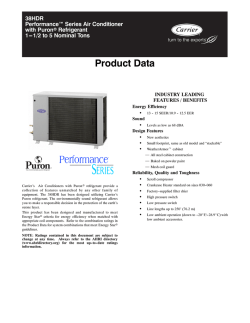
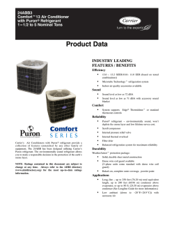
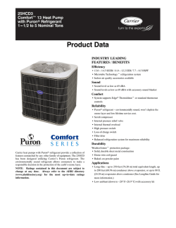
© Copyright 2026