
Posired 2 WEB:Layout 2 - Brevini Power Transmission
NEW EDITION 2015 PIV DRIVES POSIRED 2 DE EN IT FR ES PT MADE IN GERMANY www.piv-drives.com Stirnrad- und Kegelstirnradgetriebe Helical and bevel-helical gear reducers Riduttori ad assi paralleli e ortogonali Réducteurs à engrenages cylindriques et cylindro-coniques Reductores de ejes paralelos y ortogonales Redutores de eixos paralelos e ortogonais BREVINI POWER TRANSMISSION Die Industriegruppe Brevini gehört zu den Marktführern in zwei bedeutenden Industriesektoren: mechanische Antriebstechnik und hydraulische Systeme. Die Unternehmen der Gruppe, die Planetengetriebe, Stirnrad- und Kegelstirnradgetriebe sowie Winden herstellen, werden gemeinsam in einem Geschäftsbereich geführt: Brevini Power Transmission. Mit seiner weltweiten Präsenz auf den wichtigsten Weltmärkten durch ein Netz von direkten Niederlassungen ist Brevini Power Transmission ein Weltunternehmen mit starken Wettbewerbsvorteilen: vollständiges Produktangebot, weltweiter Service, Erfahrung in jeder Art von Anwendungen, von selbstbewegenden Maschinen bis hin zu Industrieanlagen. Der konsolidierte Umsatz von Brevini Power Transmission beträgt 308 Millionen Euro mit 1700 Mitarbeitern. Die Holding Brevini Group erreicht einen Umsatz von 414 Millionen Euro mit 2450 Beschäftigten. The Brevini industrial Group is a market leader in two strategic business areas: mechanical transmissions and hydraulic systems. The companies manufacturing planetary gear drives, helical and bevel-helical gearboxes, winches are managed together in the business unit: Brevini Power Transmission. Present with a direct network in the main world markets, Brevini Power Transmission is a global player with strong competitive advantages: full product range, worldwide service, experience in all possible applications, both on mobile machines and on industrial equipment. Brevini Power Transmission now has a consolidated turnover of 308 million Euro, with 1700 employees. The holding company Brevini Group has a turnover of 414 million Euro, employing 2450 people. Il Gruppo Brevini è leader di mercato in due importanti settori industriali: le trasmissioni meccaniche e i sistemi oleodinamici. Le società che producono riduttori epicicloidali, riduttori ad assi paralleli e ortogonali, argani, sono gestite in modo integrato nella business unit: Brevini Power Transmission. Presente nei maggiori mercati mondiali con una rete diretta di filiali, Brevini Power Transmission è una impresa globale con forti vantaggi competitivi: gamma completa di prodotti, attività di servizio su scala mondiale, esperienza in tutti i tipi di applicazione, dalle macchine semoventi ai sistemi industriali. Brevini Power Transmission ha un giro d'affari consolidato di 308 milioni di Euro, con 1700 dipendenti. La holding Brevini Group ha raggiunto un fatturato di 414 milioni di Euro, dando lavoro a 2450 persone. www.brevini.com www.piv-drives.com S ALES AND S ERV I C E N E T WO RK V E RTR I E BS - U N D S E RV I C E N E T Z WERK PIV Drives GmbH Justus-von-Liebig Straße 3 61352 Bad Homburg / Germany Phone +49 (0) 6172 102-0 Fax +49 (0) 6172 102-380 [email protected] www.piv-drives.com Brevini Power Transmission S.p.A. Via Luciano Brevini 1 42124 Reggio Emilia / Italy Phone +39 (0) 522 928-1 Fax +39 (0) 522 928-200 [email protected] www.brevini.com Subsidiaries Worldwide Niederlassungen Weltweit Australia Brevini Australia Pty. Ltd. Girraween, NSW 2145 Australia Tel. +61-2-8848 4000 [email protected] India Brevini India Private Limited Mumbai 400102 Tel. +91-22-26794262 [email protected] Brazil/Latin America Brevini Latino Americana Industria e Comercio Ltda. 13487-220 Limeira Sao Paulo Tel. +55-19-34468600 [email protected] Japan Brevini Japan Ltd. 650-0047 Kobe Tel. +81(0)78-304-5377 [email protected] Canada Brevini Canada Ltd. Toronto ON M9W 5R8 Tel. +1-416-6742591 [email protected] China Shanghai Brevini Gearboxes Co. ,Ltd Xuhui District, 200030 Shanghai Tel. +86-21-3356 1901 3356 1902 [email protected] Korea Brevini Korea Co. Ltd. 1254 Seoul Tel. +82-2-2065-9563/4/5 [email protected] Mexico Brevini de Mexico S.A. de C.V. 76120 Querétaro Tel. +52-4422-100389(104889) (104679) Subsidiaries Europe Niederlassungen Europa New Zealand Brevini New Zealand Ltd. PO Box 58-418 Greenmount Auckland Tel. +64-9-2500050 [email protected] South Africa Brevini Power Transmission South Africa Pty Ltd. 1504 Benoni, Johannesburg Tel. +2711421-9949 [email protected] South East Asia Brevini S. E. Asia Pte. Ltd. Singapore 608780 Tel. +65-6356-8922 [email protected] USA Brevini USA, Inc. Yorktown, IN 47396 Tel. +1-765-759-2300 [email protected] [email protected] Denmark Brevini Danmark S.A. 2690 Karlslunde Tel. +45-461-54500 [email protected] Finland Brevini Finland Oy. 02270 Espoo Tel. +358-20-743 1828 [email protected] France Brevini Power Transmission France 69516 VAULX EN VELIN Cedex Tel. +33(0) 4728-12555 [email protected] Ireland Brevini Ireland Ltd. Allenwood, Naas, Co. Kildare Tel. +353-45-890100 [email protected] Netherlands Brevini Nederland B.V. 2408 AB Alphen aan de Rijn (Nederland) Tel. +31-172-476464 [email protected] Norway Brevini Norge AS 3255 Larvik Tel. +47 33 11 71 00 [email protected] Russia Brevini Russia 196233 Sankt Petersburg Tel. +7 812 380 2162 [email protected] Spain Brevini España, S. A. 28350 Ciempozuelos (Madrid) Tel. +34-91-8015165 [email protected] Sweden Brevini Svenska AB. 60223 Norrköping Tel. +46-11-4009000 [email protected] Turkey Brevini Power Trasmission Reduktor ve San. Tic. Ltd. Sti 34775 Istanbul Tel. +90 216 540 59 09 [email protected] UK Brevini Power Trasmission UK Warrington WA1 1QX Tel. +44-1925-636682 [email protected] PIV Division DN15 8NJ Scunthorpe, North Lincolnshire Tel. +44 (1724) 281868 [email protected] Distributors Handelsvertretungen Bosnia and Herzigovina PORD d.o.o. 11000 Beograd Tel. +381 (0)11 3241-248 [email protected] Egypt Heavy Ind. Services Co. 11361 Cairo Tel. +202-2672479-480 [email protected] Iran Sepidan Tejarat Eng. & Trad. 15868 Tehran Tel. +98-21-8757636 [email protected] Montenegro PORD d.o.o. 11000 Beograd Tel. +381 (0)11 3241-248 [email protected] Serbia PORD d.o.o. 11000 Beograd Tel. +381 (0)11 3241-248 [email protected] China Shanghai Deuchi Machinery 201612 Shanghai Tel. +86-21-5764-3531 only Variators [email protected] Greece VIOMER – T. Kotzabassiakos 14122 Neo Irakleio/Athens Tel. +30-210-2852048 [email protected] Italy Favari Variatori SPA 20157 Milano Tel. +39-02-3570441 only Variators [email protected] Pakistan Brady & Co of Pakistan Ltd. Karachi 74000 Tel. +92 21 23 10367 brady@ [email protected] Slowakia IOW Trade Sp. Z o. o. 04-761 Warszawa Tel.+48 (22) 615 81 21 [email protected] Poland IOW TRADE Sp. z.o.o. 04-761 Warszawa Tel. +48-22-5125660 [email protected] Slovenia Sensor d.o.o. 2000 Maribor Tel. +386-2-6131831 [email protected] Czech Rep. IOW CZ s.r.o. 74705 Opava Tel. +420 553654803 [email protected] India K.L. Engineering Works Pvt. Ltd. Kolkata – 700 013, West Bengal Tel. +91 33 22116206 only Variators [email protected] Japan K. Brasch & Co. Ltd. Tokyo (J-104-0052) Tel. +81-3-55607591 only Variators Spain Mecanica Moderna S.A. 08005 Barcelona Tel. +34-93-3000357 only Variators [email protected] Switzerland Hans Meier AG 8627 Grüningen Tel. +41 44 936 70 20 [email protected] Taiwan KCW Eternal Enterprise Co. Ltd 702 Tainan Tel. +886 6296 5396 [email protected] USA AC Compacting LLC North Brunswick, NJ 08902-7266 Tel. +1-732-2496900 only Variators [email protected] Inhaltsverzeichnis Index Produktbeschreibung 4 Product description 6 Symbole dieses Kataloges 16 Symbols in the catalogue 16 Getriebekonzept Bauarten Getriebelagen Gehäuseflächen Wellenanordnungen und Drehrichtungen Bestellbezeichnung Getriebeauswahl Gear unit conception 17 17 18 19 26 Construction types Mounting positions Carter faces Shaft positions and sense of rotation Designation for order Gear unit selection 28 Technische Daten Leistungen und Drehmomente Wärmegrenzleistungen Gehäuseoberflächen Ist-Übersetzungen Massenträgheitsmomente Maßblätter Maßblätter-Übersicht Stirnradgetriebe Kegelstirnradgetriebe Kompaktgetriebe Weitere Gehäusebohrungen Durchgehende Antriebswelle Zusätzliche Welle Hohlwelle mit Passfedernut Hohlwelle mit Passfedernut und Labyrinth Hohlwelle mit Schrumpfscheibe Hohlwelle mit Schrumpfscheibe und Labyrinth Flanschwellen Rücklaufsperren Drehmomentstützen Powers and torques Thermal capacities Housing surfaces Exact ratios Mass moment of inertia 40 40 40 58 63 Dimensions Overview of dimension drawings 67 Helical gear units Bevel-helical gear units Compact drives Additional casing holes Double extended input shaft Additional shaft Hollow-shaft with keyway Hollow shaft with keyway and labyrinth Hollow shaft with shrink disc Hollow shaft with shrink disc and labyrinth Flanged shafts Backstops Torque reaction arms 68 88 110 126 133 136 137 138 139 140 141 142 144 40 40 40 58 63 67 68 88 110 126 133 136 137 138 139 140 141 142 144 Motor attachements 146 158 158 158 Motor bell housings Motor base plate Swing base Motor scope Schmierung, Kühlung Lüfterkühlung Kühlschlangen Flanschpumpe Motorpumpe Separate Kühlschmieranlage 30 Tecnical data Motoranbauten Motorlaternen Motorplatte Motorschwinge Motorkonsole 17 17 18 19 26 146 158 158 158 Lubrication, cooling 159 161 163 163 163 Fan cooling Cooling coils Flange pump Motor pump Separate cooling and lubrication system 159 161 163 163 163 Dichtungssysteme 164 Sealing systems 164 Hilfsantrieb 165 Auxiliary drive 165 Radial- und Axialbelastungen (Fax-Formular) 166 Radial and axial loads (fax form) 166 Lagernummerierung und Drehrichtung in der Ausgabedatei des Berechnungsprogramms 167 Bearing numbering and sense of rotation in the output file of the calculation program 167 Umrechnungsfaktoren 168 Conversion factors 168 1 Indice Index Descrizione del prodotto 8 Description du produit 10 Simboli nel catalogo 16 Symboles du catalogue 16 Caratteristiche dei riduttori Tipi di riduttori Posizioni di montaggio Superfici della carcassa Disposizione degli alberi e sensi di rotazione Designazione per l’ordinazione Selezione del riduttore Conception des réducteurs 17 17 18 19 26 Types de réducteurs Position de montage Faces du carter Position des arbres Désignation pour commande Définition du réducteur 32 Dati tecnici Potenze e momenti torcenti Potenza termica limite Superfici carcasse Rapporti di trasmissione esatti Momenti d’inerzia Dimensioni Indice pagine dimensionali 17 17 18 19 27 34 Caractéristiques techniques 40 40 40 58 63 Puissances et couples Puissance thermique limite Surfaces carter Rapports réels Moment d’inertie 40 40 40 58 63 67 Encombrement Sommaire feuilles d’encombrements 67 Riduttori ad assi paralleli Riduttori ad assi ortogonali Riduttori compatti 68 88 110 Réducteurs à arbres parallèles Réd. cylindro-coniques Réducteurs compacts 68 88 110 Forature supplementari carcassa Alberi di entrata bisporgenti Alberi addizionali Alberi cavi con cava per linguetta Alberi cavi con cava per linguetta e labirinto Alberi cavi con calettatore Alberi cavi con calettatore e labirinto Alberi con flangia Antiretro Bracci di reazione 126 133 136 137 138 139 140 141 142 144 Autres alésages du carter Arbres traversants Arbre additionels Arbres creux avec clavette Arbre creux avec rainure de clavette et labyrinthe Arbres creux avec frette de serrage Arbre creux avec frette de serrage et labyrinthe Arbres avec bride Antidévireur Bras de réaction 126 133 136 137 138 139 140 141 142 144 Accoppiamento con motore Flange attacco motore Sella porta motore Basamento per motore Staffa porta motore Combinaisons avec moteur 146 158 158 158 Lanternes de moteurs Châssis support moteur Base pour moteur Console moteur Lubrificazione, raffreddamento Raffreddamento con ventola Raffreddamento con serpentina Pompa flangiata Pompa motorizzata Impianto lubrificazione e raffreddamento separato 146 158 158 158 Lubrification, refroidissement 159 161 163 163 163 Refroidissement avec ventilateur Refroidissement avec serpentin Pompes attelées Moto-pomps Systèmes de lubrification et refroidissement séparés 159 161 163 163 163 Tenute 164 Systèmes d‘étanchéité 164 Azionamento ausiliario 165 Groupes de virage 165 Carichi radiali e assiali (modulo fax) 166 Forces radiales et axiales (formulaire fax) 166 Cuscinetti e sensi di rotazione nel file in uscita dal programma di calcolo 167 Numérotation du palier et sens de rotation dans le fichier de sortie du programme de calcul 167 Fattori di conversione 168 Facteurs de conversion 168 2 Indice Indice Descripción del producto 12 Descrição produto 14 Símbolos 16 Símbolos 16 Concepción de reductores Tipos de reductores Posiciónes de montaje Superficies de la carcasa Disposición de ejes y sentidos de rotación Designación de pedido Especificación de reductor Concepção dos redutores 17 17 18 19 27 Modos de construção Posições de montagem Superfícies da carcaça Disposições dos eixos e sentidos da rotação Designação de pedida Selecção de redutor 36 Datos técnicos Potencias y pares Potencias térmicas Superficies de carcasa Relaciones exactas Momentos de inercia 17 17 18 19 27 38 Características técnicas Potência y torques Potências termicas Superfícies da carcaça Redução real Momentos de inércia de massa 40 40 40 58 63 40 40 40 58 63 Dimensiones Sumario de los dibujos de dimensiones 67 Dimensões Vista geral dos dimensionais 67 Reductores de ejes paralelos Reductores de ejes perpendiculares Reductores compactos 68 88 110 Redutores eixos paralelos Redutores eixos angulares Redutores compactos 68 88 110 Agujeros suplementarios en la carcasa Ejes pasantes Ejes adicionales Ejes huecos con chavetero Eje hueco con chavetero y laberinto Ejes huecos con disco de contracción Eje hueco con disco de contracción y laberinto Ejes con brida Antirretrocesos Brazos de reacción 126 133 136 137 138 139 140 141 142 144 Otros furos de carcaça Eixos de ponta dupla Eixos adicionais Eixos ocos com chavetera Eixo oco com chavetera e labirinto Eixos ocos com disco de contração Eixo oco com disco de contração e labirinto Eixos flangeados Contra-recuos Braços de troque 126 133 136 137 138 139 140 141 142 144 Fijación del motor Campanas para motores Bancada para motores Base motores Pedestal para motores Fixação do motor 146 158 158 158 Laternas do motor Suporte para motores Base para motores Pedestais para motores Lubrificación, refrigeración Refrigeración con ventilador Serpentín de refrigeración Bombas embridadas Motobombas Sistemas de lubrificación y refrigeración separados 146 158 158 158 Lubrificação, refrigeração 159 161 163 163 163 Refrigeração pela ventilação Serpentinas de refrigeração Bombas flangeadas Motobombas Instalações separadas de refrigeração e lubrificação 159 161 163 163 163 Sistemas de estanqueidad 164 Sistemas de vedação 164 Accionamiento auxiliar 165 Acionamento auxiliar 165 Fuerzas axiales y radiales (form. por fax) 166 Forças axiais e radiais (formulário fax) 166 Numeración de cojinete y sentido de la rotación en el archivo de salida del programa de cálculo 167 Enumeração do rolamento e sentido de rotação no ficheiro de emissão do programa de cálculo 167 Factores de conversión 168 Factores de conversão 168 3 Stirnradgetriebe - Kegelstirnradgetriebe - Kompaktgetriebe POSIRED 2 Die moderne Getriebebaureihe POSIRED 2 der PIV Drives besticht durch ihre Zuverlässigkeit und Flexibilität. Die Überlegenheit und hohe Qualität dieser Getriebe folgt aus der konsequenten und ständigen Innovation in den Bereichen Konstruktion, Material und Produktion. Die Getriebe der PIV erfüllen höchste Anforderungen an Leistung und Zuverlässigkeit und überzeugen durch ihre hohe Wirtschaftlichkeit und Effizienz. Gehäuse • Kompakte Blockgehäuse für die Baugrößen 10 bis 31; • geteilte Gehäuse für die Baugrößen 35 bis 85; • große Einbauräume für leistungsfähige Wälzlager • die konstruktive Gestaltung sichert eine leichte Montage und Demontage der Getriebe; • die Gestaltung erfolgte nach den neuesten Erkenntnissen der Akustik, um eine stärkere Geräuschreduzierung und eine höhere Gehäusefestigkeit bei gleichzeitigen Gewichtseinsparungen zu erreichen; • Werkstoff: Standard ist Grauguss, auf Wunsch Sphäroguss oder stahlgeschweißte Gehäuse. Das PIV Drives-Qualitätssicherungssystem für Konstruktion, Entwicklung, Produktion, Montage und Kundendienst nach ISO 9001:2000 gewährleistet einen stets gleichbleibend hohen Weltklasse-Qualitätsstandard. Verzahnungen • Stirnräder schrägverzahnt, geräuschminimiert, einsatzgehärtet und geschliffen; • Wärmebehandlung nach höchsten Qualitätsanforderungen in der hauseigenen Härterei; • Profilkorrekturen für optimales Tragverhalten; • Kegelräder mit Zyklo-Palloid-Verzahnung, gehärtet, geläppt, HPGS oder geschliffen; • Berechnungsnachweise nach DIN 3990, ISO 6336, AGMA und Vorschriften der Klassifikationsgesellschaften möglich; • Verzahnungsqualität 6 nach DIN. POSIRED 2 ist ein „intelligentes“ Getriebekonzept mit überzeugenden Vorteilen für unsere Kunden: • optimale Verfügbarkeit und kurze Lieferzeiten durch einen hohen Grad der Standardisierung; • kosteneffiziente Getriebeauswahl für jede Anwendung durch fein gestufte Baugrößen; • hohe Produktqualität durch robuste Bauweise; • die große Produktflexibilität ermöglicht vielfältige Einsatzmöglichkeiten; • maßgefertigte Produktion auf Basis eines Baukastensystems. Wellen Am Abtrieb serienmäßig verfügbar: • einfache Vollwelle • durchgehende Vollwelle • Hohlwelle mit Passfeder • Hohlwelle mit Schrumpfscheibe • Flanschwelle. Am Antrieb serienmäßig verfügbar: • einfache Vollwelle • bei Stirnradgetrieben durchgehende Antriebswellen • bei allen Getrieben herausgeführte Zwischenwellen Bauarten • 1- bis 4-stufige Stirnradgetriebe • 2- bis 4-stufige Kegelstirnradgetriebe • 3 und 4-stufige Kompaktgetriebe • 25 Baugrößen nach dem Baukastenprinzip. Bau- und Ausführungsformen • Horizontale, vertikale und stehende Aufstellung mit Befestigung an allen 6 Gehäuseflächen; • Kompaktantriebe als Kegelstirnradgetriebe; • Kompaktantriebe als Kegelstirnradgetriebe mit vertikalen Abtriebswellen; • Abtrieb mit Vollwelle, Hohlwelle mit Passfeder oder Schrumpfscheibe, Flanschwelle; • mit Motorlaterne für alle Ausführungsformen; • mit Unterkonstruktionen zur Aufnahme von Motor und Getriebe; • mit Rücklaufsperre; • mit Hilfsantrieb; • mit Überholkupplung; • mit Abtriebsflansch für Anbauten (z. B. Rührwerkslaternen). Passfedern nach DIN 6885/1 gehören zum Lieferumfang. Zentrierbohrungen an Wellenenden nach DIN 332 Form DS. D [mm] 20 25...30 35 40...50 60...85 > 85 Gewinde M6 M10 M12 M16 M20 M24 Wälzlager Die Bemessung der Wälzlagerlebensdauer berücksichtigt die hohen Erwartungen des Maschinen- und Anlagenbaus. Abtriebsdrehmomente • T2: von 1 000 bis 2 000 000 Nm Übersetzungen • iN = 1,25 bis 710 mit Standardgetrieben; • iN > 710 durch Kombination von POSIRED 2-Getrieben untereinander oder durch Kombination mit anderen PIV Drives oder Brevini Getrieben. 4 Stirnradgetriebe - Kegelstirnradgetriebe - Kompaktgetriebe Rücklaufsperren Sind serienmäßig verfügbar, in einem geschlossenen Gehäuse leicht zugänglich montiert. Abdichtungen Serienmäßig verfügbare Abdichtsysteme für An- und Abtriebswellen sind: • Radialwellendichtringe in verschiedenen Werkstoffen, • Radialwellendichtringe mit zusätzlicher Staublippe, • zweiter Radialwellendichtring mit zwischenliegender fettgefüllter Kammer, • fettgeschmierte Labyrinthabdichtungen auch mit Radialwellendichtringen, • berührungsfreie Abdichtungen, • Wartungsdeckel mit wiederverwendbarer Dichtung. Zubehör • Heizstab für den Betrieb bei großer Kälte; • Betriebsüberwachungssysteme für Drehzahl, Drehmoment, Temperatur, Öldurchlauf, Ölstand etc.; • Diagnosesysteme z. B. für Lagerüberwachung. Allgemeines • Maßblätter stehen als CAD-Dateien für verschiedene DV-Systeme und Schnittstellen zur Verfügung. • Computerprogramme zur Antriebsauswahl. • Verzahnungs-, Wellen- und Lagerberechnung mit Berechnungsnachweisen. • Die Schutzart entspricht IP 55. • Angaben zum Getriebegewicht und zur Getriebeölmenge sind Richtwerte. Genaue Werte können dem Getriebetypenschild entnommen werden. Schmierung • Zahnräder und Wälzlager werden standardmäßig tauchgeschmiert. • Optional sind standardisierte Einspritz-Schmiersysteme mit Wellen- oder Motorpumpe verfügbar. • Ölpeilstab als Standardlösung bei Horizontal-Getrieben. • Ölschauglas als Standardlösung bei Vertikalgetrieben. Lieferumfang, Aufstellung und Inbetriebnahme Die Lieferung erfolgt ohne Ölfüllung. Ölsorte und Ölmenge nach Typenschild. Empfohlene Qualität: CLP nach DIN 51517. Kühlung Serienmäßig verfügbare Zusatzkühleinrichtungen sind: • mechanische oder elektrische Lüfterkühlung, • Kühlschlange, • externe Ölkühler wie Öl-Luft-Kühler und Öl-WasserKühler. Die Standardkonservierung bei normalen Transport- und Lagerbedingungen ist für einen Zeitraum von 6 Monaten ausreichend. Drehmomentstützen Auf Wunsch lieferbar in ein- oder zweigelenkiger Ausführung. Aufstellung und Inbetriebnahme nach PIV Drives Betriebsanleitungen: 999-9999-DOK001 und 430-0000-DOK001 Motoren und Antriebe • Motoren nach DIN, VDE, IEC oder anderen Normen • drehzahlgeregelte Drehstromantriebe mit dem erforderlichen Zubehör; • Antrieb durch Kombination mit mechanisch stufenlosen PIV Drives Getrieben. Auf Anfrage liefern wir den gesetzlich vorgeschriebenen Berührungsschutz an umlaufenden Teilen. Für Hohlwellengetriebe werden Schutzhauben für die Schrumpfscheibe vorgesehen. Motorbefestigungen Serienmäßig verfügbar sind: • Motorlaternen • Motorschwingen • Motorkonsolen • Motorplatten zur Aufnahme des Motors. Kupplungen Am Abtrieb passend zu den Serienabtriebswellen und Getriebedrehmomenten: • Elastische Kupplungen • Zahnkupplungen • Tonnenkupplungen • Lamellenkupplungen • weitere Kupplungen auf Anfrage. Am Antrieb passend zu den Serienantriebswellen und Getriebedrehmomenten: • Elastische Kupplungen • Strömungskupplungen • weitere Kupplungen auf Anfrage. 5 Helical gears - bevel helical gears - compact gears POSIRED 2 is PIV Drives latest innovative product line. These superior gear units are produced with state of the art design, material, and manufacturing technologies for maximum power and reliability within a cost-effective package. The PIV Drives ISO 9001:2000 quality assurance system for design, development, production, assembly, and after-sales service guarantees an uniformly high World-class standard • The design simplifies assembly and dismantling of the gear units • Designed utilizing the latest technologies in acoustics and Finite Element Analysis to produce superior noise reduction and housing rigidity with optimal weight savings • Material: grey cast iron casting as standard, nodular cast iron or welded steel on request Gears • Helical gears for reduced noise, case hardened and ground • Heat treatment in PIV’s dedicated hardening bay for highest quality • Profile corrections for optimum inertia quality • Spiral bevel gears (cyclo-palloid tooth form) hardened and lapped, HPGS or ground • Calculation checks possible in accordance with DIN 3990, ISO 6336, AGMA and classification Company standards • Gear toothing quality 6 acc. to DIN POSIRED 2 is an “intelligent” gear concept • because the design has a high degree of standardization, giving optimum availability and short delivery times • because a cost effective selection for each application is assured by a torque-dense product range • because it offers more advantages owing to: - high product quality from a robust design - high product flexibility allows for more versatile applications and - tailor-made production from a modular construction system Shafts Available types of output shafts: • Solid shaft • Double extended solid shaft • Hollow shaft with key • Hollow shaft with shrink disc • Flanged shaft • Splined hollow or solid shaft Available types of input shafts: • Solid shaft • Double extended solid shaft for helical gear units • Additional intermediate exterior shaft end for all gear unit types Construction types • 1 to 4 stage helical gears • 2 to 4 stage bevel helical gears • 3 and 4 stage compact gear units • 25 frame sizes available Construction and product configurations • horizontal, vertical an upright designs with attachment on all 6 casing-surfaces • spiral bevel spur gears available for compact, right angle drives • right angle drives available with vertical driven shafts • with output shaft as solid, flanged, or hollow with key or shrink disk • with motor bell housing • with base plate for the motor and the drive unit • with back stop • with auxiliary drive • with overriding clutch • with flange for output side attachments Keys acc. to DIN 6885/1 supplied by PIV Drives. Center holes on the shaft ends acc. to DIN 332 form DS D [mm] 20 25..30 35 40..50 60..85 > 85 Thread M6 M10 M12 M16 M20 M24 Roller bearings The lifetime calculations of the roller bearings assumes the highest expectations of all engineering parameters Output torques T2: of 1 000 up to 2 000 000 Nm Seals Standard seal systems available for input and output shafts: • Radial shaft seals in various materials • Radial shaft seals with additional dust lip • Second radial shaft seal with intermediate grease-filled chamber • Greased labyrinth seals also with radial shaft seals • No-contact seals • Maintenance cover with reusable seal Ratios • iN = 1.25...710, for standard units • iN > 710 through a combination of POSIRED 2 units or a combination of POSIRED 2 with other PIV or Brevini units Casing • Compact one piece casings for frame sizes 10 to 31 • Split casings for frame sizes 35 to 85 • Greater bore diameters for large roller bearings with high load carrying capacity 6 Helical gears - bevel helical gears - compact gears General information • Information sheets available as CAD files for various computer systems and interfaces • Computer programs for selecting the appropriate sized drive • Calculation reports for the mechanical attributes of the gearing, shafts, and bearings • The enclosure corresponds to IP 55 • Details on the weight and the oil quantity of the gear units are standard values. The exact values are mentioned on the name plate. Lubrication • Gear wheels and roller bearings are oil-bathed as standard • Standardized injection lubrication systems with shaft or motor driven pump are available as options • Oil dipstick as standard for horizontal gear units • Oil sight glass as standard for vertical gear units Cooling Additional cooling devices available as standard: • mechanical or electrical fan cooling • cooling coil • external oil cooler with oil/air or with oil/water heat exchanger Delivery, installation and start-up Units are delivered without oil. Oil quality and quantity are specified on each unit’s name plate. Recommended oil quality: CLP according to DIN 51517. Torque arms available on request with 1 or 2 ball-and-socket joint Standard protection measures are sufficient for a period of 6 months under dry transport and storage conditions Motors and driving engines • Motors according to DIN, VDE, IEC or other standards • Speed controlled three phase current drives with the necessary accessories, • Combinations with mechanical continuously variable units of PIV Drives. Installation and start-up in accordance with PIV Drives instructions for use: 999-9999-DOK001en and 430-0000-DOK001en On request, we supply the protection from contact with moving parts required by law. Available, for gearboxes with hollow shaft, protection cover for shrink disk. Motor supports available as standard • Motor bell housings • Motor brackets • Base plates as support of the motor and the gear unit Couplings on the output shaft suitable for standard output shafts and gear torques: • Elastic couplings • Gear coupling • Barrel coupling • Multiple disc coupling • other coupling types on request on the input shaft suitable for standard drive shafts and gear torques: • Flexible couplings • Hydrodynamic couplings • other couplings on request Backstops available as standard, accessible in a closed housing Accessories • Heating element for very cold conditions • Operational monitoring systems for speed, torque, temperature, oil flow, oil level, and other conditions • Diagnostic systems also available 7 Riduttori ad assi paralleli ed ortogonali – riduttori compatti POSIRED 2 è la più recente e innovativa gamma di prodotti PIV Drives. Questa serie di riduttori nasce da moderni standard progettuali ed è prodotta con materiali e processi altamente affidabili, per garantire la massima potenza ed affidabilità a costi contenuti. Il sistema qualità PIV Drives, conforme alle norme ISO 9001:2000, garantisce un altissimo e costante livello di qualità. • Design costruttivo che semplifica il montaggio e lo smontaggio dei riduttori. • Progettata in conformità con i più avanzati studi sull’acustica; ottimizzati con “Finite Element Analysis” per ottenere rumorosità ridotta, rigidità strutturale e riduzione dei pesi. • Materiali: ghisa grigia. Su richiesta ghisa sferoidale oppure acciaio elettrosaldato. Ingranaggi • Ingranaggi cilindrici a dentatura elicoidale cementati e rettificati per ridurre la rumorosità • Trattamento termico realizzato all’interno degli stabilimenti PIV Drives per ottenere la massima qualità. • Correzione del profilo dei denti per un ottimale ingranamento. • Ingranaggi conici a dentatura Cyclo Palloid cementati, lappati, HPGS oppure rettificati • Verifica dei calcoli secondo DIN 3990, ISO 6336, AGMA o secondo gli standard richiesti dal cliente • Qualità ingranaggi 6 secondo DIN. POSIRED 2 è una serie di riduttori „intelligente” che offre diversi vantaggi al cliente: • tempi di consegna rapidi, grazie alla elevata modularità che garantisce una costante disponibilità dei componenti. • grandezze sviluppate armonicamente, così da permettere la più economica scelta del riduttore in ogni campo applicativo. • alta qualità del prodotto • elevate possibilità di applicazione, grazie alla adattabilità del riduttore • possibile personalizzazione del prodotto, grazie al sistema costruttivo modulare. Alberi Alberi di uscita disponibili di serie: • Albero pieno sporgente • Albero pieno bisporgente • Albero cavo con cava per linguetta • Albero cavo con calettatore • Albero flangiato • Albero cavo o pieno scanalato Alberi di entrata disponibili di serie: • Albero pieno sporgente • Albero pieno bisporgente per riduttori ad assi paralleli • Sporgenza albero intermedio per tutti i tipi di riduttore Tipi di riduttori • Riduttori ad assi paralleli da 1 a 4 stadi • Riduttori ad assi ortogonali da 2 a 4 stadi • Riduttori compatti a 3 o 4 stadi • 25 grandezze disponibili Forme costruttive ed esecuzioni • Montaggio orizzontale e verticale con possibilità di fissaggio su tutte le sei facce della carcassa • Riduttori compatti ad assi ortogonali • Riduttori compatti ad assi ortogonali con albero di entrata verticale • con albero di uscita pieno, albero cavo con linguetta o con calettatore. • con flangia attacco motore • con base per sopporto motore e riduttore • con dispositivo antiretro • con motore ausiliario • con frizione di esclusione • con flangia di attacco accessori in uscita Linguette secondo DIN 6885/1 fornite da PIV Drives. Forature di centraggio sulle estremità degli alberi secondo DIN 332 form DS D [mm] 20 25..30 35 40..50 60..85 > 85 Filettatura M6 M10 M12 M16 M20 M24 Cuscinetti a rulli Durata dei cuscinetti a rulli calcolata secondo i più severi standard progettuali. Coppia in uscita T2: da 1 000 a 2 000 000 Nm Tenute I sistemi di tenuta per alberi in entrata e in uscita sono: • Anelli di tenuta radiale in diversi materiali • Anelli di tenuta radiale con labbro parapolvere • Secondo anello di tenuta radiale con intercapedine riempita di grasso • Tenuta a labirinto con grasso, oppure con anelli di tenuta radiali • Tenute in assenza di contatto • Cappellotto di manutenzione con tenuta riutilizzabile Rapporti • iN = 1,25 fino a 710 con riduttori standard • iN > 710 combinando riduttori POSIRED2 oppure combinando POSIRED 2 con altri riduttori PIV e/o Brevini Carcassa • Carcassa monoblocco per le grandezze da 10 a 31 • Carcassa in 2 semigusci per grandezze da 35 a 85 • Cuscinetti a rulli con elevate capacità di carico 8 Riduttori ad assi paralleli ed ortogonali – riduttori compatti Informazioni generali • Disegni dimensionali sono disponibili in formato CAD per diversi sistemi operativi. • Programmi per la scelta di riduttore. • Report di calcolo degli ingranaggi, alberi e cuscinetti • Protezione IP 55. • I valori riguardanti il peso e la quantità d’olio sono indicativi. I valori precisi sono indicati sulla targhetta del riduttore. Lubrificazione • Lubrificazione dei cuscinetti a rulli a bagno d’olio (standard). • Sistemi di lubrificazione ad iniezione con albero di comando o pompa motorizzata disponibili a richiesta. • Astina di livello olio per riduttori orizzontali (standard). • Tappi trasparenti per riduttori verticali (standard). Raffreddamento Sistemi di raffreddamento supplementari disponibili di serie: • Raffreddamento meccanico oppure elettrico con ventola. • Raffreddamento con serpentina. • Scambiatore di calore esterno olio/acqua oppure olio/ aria. Stato di fornitura, installazione e messa in servizio I riduttori sono forniti senza lubrificante; tipo e quantità d’olio da utilizzare sono indicate sulla targhetta. Qualità d’olio raccomandata: CLP secondo DIN 51517. Le misure di protezione standard sono sufficienti per 6 mesi in condizioni di trasporto e stoccaggio normali. Bracci di reazione disponibili a richiesta anche con 1 o 2 snodi Installazione e messa in servizio secondo le istruzioni d’uso PIV Drives: 999-9999-DOK001it 430-0000-DOK001it Motori e azionamenti • Motori secondo DIN, VDE, IEC oppure altre norme • Azionamenti trifase a velocità controllata con gli accessori opportuni. • Azionamento combinato con variatori di velocità meccanici PIV Drives. A richiesta forniamo la protezione delle parti mobili secondo le disposizioni di legge. Per riduttori con alberi cavi sono previsti cappellotti di protezione per il calettatore. Sistemi di attacco motore disponibili di serie: • Flangia attacco motore • Staffa portamotore • Basamento di fissaggio per motore e riduttore Giunti in uscita, adattabili agli alberi d‘uscita e alla trasmissione di coppia: • Giunti elastici • Giunti a ingranaggio • Giunti a botte • Giunti multidisco • Altri tipi di giunto disponibili a richiesta in entrata, adattabili agli alberi in entrata e alla trasmissione di coppia: • Giunti elastici • Giunti idrodinamici • Altri tipi di giunto disponibili a richiesta Dispositivi antiretro Disponibili di serie, installati in una carcassa chiusa e facilmente accessibili. Accessori • Riscaldatori per condizioni ambientali molto fredde. • Sistemi di monitoraggio per velocità, per momento. torcente, temperatura, portata e livello olio: a richiesta. • Altri sistemi diagnostici: a richiesta. 9 Réducteurs à engrenages cylindriques et cylindro-coniques, réducteurs compacts POSIRED 2 est un programme de réducteurs éprouvé au cours de longues années et perfectionné continuellement selon le niveau de la technique le plus actuel. Le système d’assurance qualité de PIV Drives pour étude, développement, production, montage, service après vente, suivant DIN ISO 9001 :2000, garantit une haute qualité standard constante. POSIRED 2 est un concept de réducteurs intelligent • en réduisant le nombre de repères, mais en multipliant leur utilisation dans différents types de réducteurs (niveau élevé de la standardisation et du degré de réutilisation des pièces en vue d’optimiser leur disponibilité et de réduire les délais), • en étageant au plus fin les tailles des réducteurs, donc leurs couples admissibles, permettant ainsi pour chaque installation une sélection meilleur marché, • en présentant plus d’avantages par: - disponibilité plus rapide - possibilités de montage variables et universelles, - degré supérieur de standardisation de l’installation, (exécution sur mesure par éléments modulaires standard). Carter • Carter monobloc pour les tailles entre 14 et 31 • Carter avec plan de joint pour les tailles 35 à 85 • Large espace pour montage de roulements à grande capacité portante • La configuration constructive assure la facilité du montage et du démontage • La configuration a été réalisée suivant le plus récent état des connaissances en acoustique • Matière: fonte grise en standard, fonte à graphite sphéroïdal ou acier mécano-soudé sur demande Engrenages • Engrenages cylindriques CTR à denture hélicoïdale, optimisés pour limiter le bruit • Qualité constante garantie par la cémentation dans notre propre atelier de traitement thermique • Correction de profil pour optimiser la portée • Engrenages coniques (denture cyclopalloïde) cémentés, trempés, rodés, HPGS ou rectifiés • Possibilité d’exécution du calcul des dentures selon DIN 3990, ISO 6336, AGMA et prescriptions des sociétés de classification. • Denture en qualité 6 selon DIN Arbres Disponibles en série en PV • arbre plein • arbre plein traversant • arbre creux avec clavette • arbre creux avec frette de serrage • arbre à bride Disponibles en série en GV • arbre plein • arbre plein traversant pour les réducteurs à engrenages cylindriques • arbre intermédiaire sortant supplémentaire chez tous les types de réducteurs Types de réducteurs • de1 à 4 trains d’engrenages parallèles • de2 à 4 trains d’engrenages cylindro-coniques • compacts de 3 et à 4 trains d’engrenages • 25 tailles selon le principe de construction modulaire Formes et exécutions • Installation horizontale, verticale ou debout, avec fixation sur les 6 cotés du carter • Réducteur cylindro-conique en tant qu’unité compacte, aussi avec arbre d’entrée vertical • Sortie à arbre plein, arbre creux à rainure de clavette ou à frette de serrage, ou à arbre à bride • Avec lanterne moteur pour toutes les exécutions • Avec châssis pour fixation du moteur et du réducteur • Avec anti-dévireur • Avec groupe de virage connecté par roue libre • A bride pour fixation d’accessoires coté PV, par exemple d’une lanterne pour agitateur Clavettes selon DIN 6885/1, livreés par PIV drives. Trous de centrage des bouts d’arbre selon DIN 332 forme DS D [mm] 20 25..30 35 40..50 60..85 > 85 Filet M6 M10 M12 M16 M20 M24 Couples en sortie • T2: de 1 000 jusqu’à 2 000 000 Nm Roulements Le dimensionnement de la durée de vie des roulements tient compte des hautes exigences de la construction mécanique et de tous les paramètres. Rapports de réduction • iN = 1.25...710, pour unités standards • iN > 710 en combinant des unités POSIRED 2 entre elles, ou en les combinant avec d’autres appareils de PIV ou de Brevini Etanchéité Systèmes d’étanchéité disponibles en série pour arbres d’entrée et de sortie: • Joints d’étanchéité annulaires en différentes matières • Joints d’étanchéité avec lèvre antipoussière supplémentaire • 2-ème joint d’étanchéité avec réserve de graisse 10 Réducteurs à engrenages cylindriques et cylindro-coniques, réducteurs compacts Accessoires • Canne de réchauffage pour ambiance très froide • Systèmes de surveillance pour vitesse, couple, température, débit d’huile, niveau d’huile, etc. • Systèmes de diagnostic comme la surveillance des roulements ou similaires • Joints à labyrinthe avec bourrage de graisse et aussi avec anneaux d’étanchéité • Joints sans contact • Couvercle de visite avec joints réutilisables Lubrification • Engrenages et roulements sont lubrifiés en standard par barbotage • En option – systèmes standardisés de lubrification sous pression avec pompe attelée ou avec groupe moto-pompe • Réglette-jauge d’huile en série pour montage horizontal, sinon niveau visuel Généralités • Feuilles d’encombrement sur CAO/DAO suivant différents systèmes de traitement de l’information et pour différentes interfaces • Programmes ordinateur pour la sélection des réducteurs, le calcul des engrenages, des arbres et des roulements, avec notices de calcul • La classe de protection correspond à IP 55 • Les informations sur le poids et la quantité d’huile des réducteurs sont des valeurs indicatives. Les valeurs précises se trouvent sur la plaquettes signalétique. Refroidissement Dispositifs de refroidissement additionnel disponibles en standard: • ventilateur mécanique ou électrique • serpentin à circulation d’eau • groupe réfrigérant extérieur à échangeur huile/air ou huile/eau Volume de la fourniture - mise en fonctionnement Livraison sans huile, qualité et quantité d’huile suivant les prescriptions de la plaque signalétique Bras de réaction Livrables sur demande avec 1 ou 2 articulations à rotule Conservation standard pour conditions de transport et de stockage normales, suffisantes pour une durée de 6 mois. Moteurs et unités d’entraînement • Moteurs électriques suivant DIN, VDE, IEC ou autres standards • Moteurs alternatifs triphasés à vitesses variables asservis par les accessoires nécessaires • Combinaisons avec des variateurs de vitesses mécaniques de PIV Drives. Installation et mise en route suivant les notices de PIV Drives 999-9999-DOK001fr et 430-0000-DOK001fr En option nous fournissons les protections contre les parties tournantes, nécessaires suivant la législation. Les appareils à arbres creux sont livrés avec le capot de protection de la frette de serrage. Fixation des moteurs disponibles en standard : • Lanternes moteurs • Consoles pour moteurs • Châssis pour fixation du moteur et du réducteur Accouplements en PV s’adaptant aux arbres et aux couples des réducteurs • accouplements élastiques • accouplement à denture • accouplements à tonnelets • accouplements à lamelles • autres accouplements sur demande en GV s’adaptant aux arbres et aux couples des réducteurs • accouplements élastiques • coupleurs hydrauliques • autres accouplements sur demande Anti-dévireurs disponibles en série, montés de manière facilement accessible dans un carter fermé. 11 Reductores de engranajes cilíndricos y de ruedas dentadas cilindricas y cónicas POSIRED 2 es la más reciente e innovadora gama de productos PIV. Esta serie de reductores nace de modernos está producida con los más altos niveles de diseño, materiales y tecnologías de fabricación, para garantizar la máxima potencia y fiabilidad al menor coste. El sistema de calidad de PIV Drives, conforme a la norma ISO 9001:2000, garantiza un altísimo y constante nivel de calidad. POSIRED 2 es un concepto de engranajes inteligente que ofrece diversas ventajas al cliente: • Plazos de entrega cortos, gracias a la elevada modularidad que garantiza una constante disponibilidad de los componentes. • Tamaños desarrollados armónicamente, permitiendo la selección más económica del reductor en cada caso. • Alta calidad del producto: • Elevada disponibilidad de aplicación, gracias a la adaptabilidad del reductor. • Posibilidad de personalización del producto, gracias a su sistema constructivo modular. Carcasas • Carcasa monobloc para los tamaños 10 a 31 • Carcasa en dos partes para los tamaños 35 a 85 • Rodamientos de rodillos conelevada capacidad de carga • Diseño constructivo que simplifica el montaje y desmontaje del reductor • Diseñados conforme a los más avanzados estudios de acústica; optimizados con “Análisis por elementos Finitos” para obtener una sonoridad reducida, rigidez estructural y reducción de peso • Materiales: fundición gris. Bajo demanda fundición esferoidal o acero electrosoldado Engranajes • Engranajes helicoidales cementados y rectificados, de ruido reducido • Calidad constante gracias a la cementación en nuestra propria sección de tratamiento térmico • Corrección del perfil para capacidad de carga óptima • Engranajes cónicos (dentado Cyclo Palloid) cémentados, templados, lapeados, HPGS o rectificados • Posibilidad de ejecución del cálculo de los dentados según DIN 3990, ISO 6336, AGMA y según las prescripciones de las sociedades de clasificación • Dentados en calidad 6 según DIN Tipos de reductores • Reductores de ejes paralelos de 1 a 4 etapas • Reductores de ejes ortogonales de 2 a 4 etapas • Reductores compactos de 3 ó 4 etapas • 25 tamaños disponibles Ejes Disponible como estándar en la salida: • Eje macizo • Eje macizo pasante • Eje hueco con chavetero • Eje hueco para disco de contracción • Eje con brida Disponible como estándar en la entrada: • Eje macizo • Eje macizo pasante para reductores de ejes paralelos • Eje adicional intermedio para todas los tipos de reductor Formas constructivas y ejecuciones • Montaje horizontal y vertical con posibilidad de fijación sobre cualquier superficie de la carcasa • Reductores compactos de ejes ortogonales • Reductores compactos de ejes ortogonales con eje de entrada vertical • Con eje de salida macizo, hueco con chaveta o con disco de contracción • Con brida para motor • Con bancada para soporte de motor y reductor • Con dispositivo antirretorno • Con embrague • Con brida para accesorios en salida Chavetas según DIN 6885/1, estan comprendidos en el sumistro de PIV Drives. Pares de salida • T2: de 1 000 hasta 2 000 000 Nm Puntos de centrado de la punta del eje según DIN 332 forma DS D [mm] 20 25...30 35 40...50 60...85 > 85 Rosca M6 M10 M12 M16 M20 M24 Reducción • iN = 1.25...710, para unidades estándar • iN > 710 por medio de una combinación de unidades POSIRED 2 entre sí o combinándolas con otras unidades de PIV o de Brevini Rodamientos El dimensionamiento de la duración de vida de los rodamientos, tiene en cuenta las altas exigencias de la construcción mecánica y de las instalaciones. 12 Reductores de engranajes cilíndricos y de ruedas dentadas cilindricas y cónicas en el eje de entrada, adecuados a los ejes de entrada y los pares normales del reductor: • Acoplamientos elásticos • Acoplamientos hidrodinámicos • Otros acoplamientos bajo demanda Estanqueidad Sistemas de estanqueidad disponibles de serie para los ejes de entrada y de salida: • Retenes de estanqueidad en varios materiales • Retenes de estanqueidad con labios adicionales antipolvo • Segundo anillo de estanqueidad con cámara de grasa intermedia • Juntas laberínticas con grasa también con anillos de estanqueidad • Juntas sin contacto • Tapa de mantenimiento con sellado reutilizable Antirretrocesos Disponibles como estándar montados de manera facilmente accesible en un cárter cerrado Accesorios • Calentador eléctrico para ambiente muy frio • Sistemas operacionales de supervisión entre otros para la velocidad, el par, la temperatura, el flujo de aceite, el nivel de aceite, etc., • Sistemas de diagnóstico como la supervision de los rodamientos o similares Lubrificación • Engranajes y rodamientos son lubrificados por inmersión como estándar • Sistemas estándar de lubrificación de inyección, con bomba accionada por eje o por motor disponibles opcionalmente • Varilla indicadora de nivel de aceite como norma para reductores horizontales, por otra parte mirillas de vista de aceite Generalidades • Hojas de información disponibles como ficheros de CAD para los distintos sistemas de ordenador e interfaces. • Programas de ordenador para la selección del engranaje, para el cálculo de los dentados, de los ejes y de los rodamientos, con los resultados del cálculo. • Clase de protección correspondiente a IP 55. • Los detalles sobre el peso y la cantidad de aceite del reductor son valores informativos. Valores exactos según las indicaciones de la chapa de características. Refrigeración Dispositivos de refrigeración adicionales disponibles como estándar: • Ventilador refrescando mecánico o eléctrico • Serpentín de refrigeración • Refrigerador de aceite externo con intercambiador de calor aire/aceite o agua/aceite Volumen de suministro – puesta en marcha Entrega sin aceite; calidad y cantidad de aceite según las indicaciones de la chapa de características Calidad recomendada: CLP según DIN 5. Brazo de reacción Disponible opcionalmente con 1 o 2 articulaciones de rótula Motores y unidades de accionamiento • Motores según DIN, VDE, IEC o otros estándares • Transmisiones de corriente trifásica con velocidad controlada y los accesorios necesarios, • Combinaciones con variadores de velocidad mecanicos de PIV Drives. Conservación estandar para condiciones de transporte y de almacenaje normales, suficiente para una duración de 6 meses. Instalación y puesta en marcha según las instrucciones de PIV Drives 999-9999-DOK001es y 430-0000-DOK001es Fijación del motor disponible como normal: • Caja de acoplamiento para embridar el motor • Soporte del motor • Bancada para el motor de accionamiento y la unidad de transmisión Opcionalmente, nosotros suministramos la protección contra el contacto con partes móviles requerida por la ley. Se entregan las unidades de engranaje de eje hueco con la tapa de protección para el disco de contracción. Acoplamientos en el eje de salida, adecuados a los ejes de salida y los pares normales del reductor: • Acoplamientos elásticos • Acoplamientos de dientes • Acoplamientos de barriletes • Acoplamientos de láminas • Otros acoplamientos bajo demanda 13 Redutores eixos paralelos e angulares – Redutores compactos POSIRED 2 é uma linha de redutores, desenvolvido, aperfeiçoado e comprovado ao longo de muitos anos, seguindo as mais avançadas tecnologias. O sistema da garantia de qualidade da PIV Drives, abrangendo projeto, desenvolvimento, produção, montagem e assistência ténica conforme ISO 9001 : 2000, assegura aos seus clientes um alto padrão de atendimento constante (certificado registrado pelo n0 12 100 16478 TMS). POSIRED 2 é uma linha de redutores inteligente • porque necessita de poucas peças nas várias aplica ções flexíveis. Alto índice de padronização e aproveitamento inteligente de peças possibilita multiplicidade de formas construtivas, disponibili dade otimizada e prazos de entrega reduzidos • porque há um escalonamento fino entre os tamanhos dos produtos, que resulta em menores diferenças de torques, e garante uma escolha econó mica na aplicação • porque traz mais benefício para nossos clientes, pela: • disponilibidade de entrega mais rápida • possibilidades na aplicação mais variável e universal • maior padronização nos projetos industriais pelo aproveitamento de redutores padronizados com „fabricação individual pelo sistema modular“ Engrenamento • engrenagens helicoidais de baixo nível de ruídos, cementados e retificados • garantia de uma qualidade uniforme no tratamento térmico nas nossas instalações • correções de perfil para otimizar a distribuição de carga • pares cónicos com engrenamento tipo „Ciclo-Palloid“, lapidados, HPGS ou retificados • comprovante de cálculos conforme DIN 3990, ISSO 6336 , AGMA e patrões de empresas classificadoras • qualidade de engrenamento 6 conforme DIN Eixos da saida de série disponíveis em: • eixo maciço simples • eixo de ponta dupla • eixo oco com chaveta • eixo oco com disco de contração • eixo flangeado na entrada de série disponíveis em: • eixos de ponta dupla nos redutores de eixos paralelos • em todos redutores as pontas de eixos intermediários são alojados nas paredes externas da carcaça Chavetas conforme DIN 6885/1 fazem parte do fornecimento de PIV Drives. Furos de centragem nas pontas dos eixos conforme DIN 332 forma DS D [mm] 20 25..30 35 40..50 60..85 > 85 Rosca M6 M10 M12 M16 M20 M24 Modos de construção - redutores de eixos paralelos com 1 a 4 estágios - redutores de eixos ortogonais com 2 a 4 estágios - redutores compactos com 3 a 4 estágios - 25 tamanhos pelo princípio do sistema modular Rolamentos o dimensionamento da vida útil dos rolamentos concidera as elevadas expetativas da construção de máquinas e equipamentos Formas construtivas • montagem horizontal, vertical ou em pé com fixação em todos 6 superfícies da carcaça • redutores compactos com engrenagens cônicas também com eixos de entrada na vertical • eixo de saida maciço, eixo oco com chaveta ou com o disco de contração, eixo flangeado • laterna para motores de todos os tipos de construção • base única para a montagem do motor e redutor • contra – recuo • acionamento auxiliar com acoplamento de sobrevelocidades • flange de fixação para montagens adicionais como por ex. laternas para agitadores Vedações Sistemas de vedação disponíveis de série para eixos de entrada e saida: • retentores em varios materiais • retentores à prova de pó • retentores duplos com câmara de graxa • anel labirinto lubrificado à graxa, também com retentor radial • vedação sem contato mecânico • tampa de manutenção com junta reutilizável Lubrificação • engrenagens e rolamentos são lubrificados através de banho de óleo • opcionalmente podem ser fornecidos sistemas de lubrificação patronizados com bombas flangeadas ou motobombas • vareta do nível do óleo de série para redutores horizontais, para outros disposições visor de nível Torques de saida • T2 : de 1 000 a 2 000 000 Nm Reduções • iN = 1,25 a 710 redutores standard • iN = > 710 pela combinação de redutores POSIRED 2 ou com outros redutores PIV Drives ou Brevini 14 Redutores eixos paralelos e angulares – Redutores compactos Refrigeração Instalações adicionais disponíveis de série: • ventilador acoplado no eixo ou acionado por motor elétrico • serpentina • radiadores externos óleo / ar ou óleo / água Fornecimento - partida Os equipamentos são fornecidos sem óleo lubrificante, a especificação do óleo e quantidade constam nos dados de plaqueta. A conservação padrão para condições normais de transporte e armazenamento é de 6 meses. Braços de troque sob encomenda dispiníveis com 1 ou 2 articulações Montagem e partida de acordo com os manuais PIV Drives : 999-9999-DOK 001pt 430-0000-DOK 001pt Motores e acionamentos • motores conforme DIN, VDE, IEC ou outras normas • motores trifásicos com variação de rotação e acessórios necessários • acionamentos combinados com variadores de velocidade PIV Drives Como opção oferecemos a proteção de acordo com as normas de segurança nas peças em rotação, bem como proteção para os discos de contração em redutores de eixo oco. Fixações dos motores disponível de série: • laternas do motor • suportes do motor • bases únicas para montar motores e redutores Acoplamentos na saída de acordo com os eixos de saída e torques: • acoplamentos elásticos • acoplamentos de engrenagens • acoplamentos de barris • acoplamentos de lâminas • outros acoplamentos sob consulta no eixo de entrada • acoplamentos elásticos • acoplamentos hidráulicos • outros acoplamentos sob consulta Contra – recuo de série disponível , montada numa caixa blindada de fácil acesso Acessórios • aquecedor para serviço em temperaturas baixas • sistemas de monitoramento da rotação, torque, temperatura, fluxo e nível de óleo etc. • sistema de diagnose para o monitoramento de rolamentos e similares Informações gerais • dimensionais à disposição nos arquivos CAD para vários sistemas de processamentos de dados e portas de acesso • programas de computador para a escolha de redutores,cálculos de engrenagens, eixos e rolamentos, com documento demonstrativo • a classe de proteção corresponde IP 55 • Insruções referentes ao peso do redutor e à quantidade de óleo lubrficante são valores informatifos.Informacões precisas encontra-se na placa do redutor. 15 Symbole dieses Kataloges Symbols in the catalogue / Simboli nel catalogo / Symboles du catalogue / Símbolos en el catálogo / Símbolos do catálogo Abmessungen / Dimensions / Dimensioni /Dimensions / Dimensiones / Dimensões Símbolo referido a los reductores PB, PC, PD, PE Símbolo para redutores PB, PC, PD, PE Símbolo referido a los reductores PLB, PLC, PLD Símbolo para redutores PLB, PLC, PLD Symbole pour type du reducteur PWC, PWD Símbolo referido a los reductores PWC, PWD Símbolo para redutores PWC, PWD Simboli che identificano i riduttori ad 1, 2, 3, 4 stadi di riduzione Symboles pour 1, 2, 3, 4 trains d‘engrenages Símbolos que identifican los reductores de 1, 2, 3 y 4 etapas de reducción Símbolos para classificação dos etágios: um estágio, dois estágios, três..., quatro... Symbols describing kind of output shaft: V = Solid shaft H = Hollow shaft with key G = Hollow shaft with shrink disc F = Flanged shaft Simboli riferiti agli alberi uscita dei riduttori: V = Albero pieno H = Albero cavo con linguetta G = Albero cavo con calettatore F = Alberi con flangia Symboles pour arbres es PV: V= Arbre plein H= Arbre creux avec clavette G= Arbre creux avec frette de serrage F= Arbre à bride Símbolos referidos a los ejes de salida de los reductores: V = Eje macizo H = Eje hueco con chaveta G = Eje hueco con disco de contracción F = Eje con brida Símbolos para eixos de saída : V= eixo maçico H= eixo oco com chaveta G= eixo oco com disco de contração F= eixo flangeado Gear unit weight [kg] Peso del riduttore in Kg Poids du réducteur [kg] Peso de reductor [kg] Peso do redutor [kg] Symbol für Getriebetypen PB, PC, PD, PE Symbol referring to gear unit type PB, PC, PD, PE Simbolo riferito ai riduttori PB, PC, PD, PE Symbole pour type du reducteur PB, PC, PD, PE Symbol für Getriebetypen PLB, PLC, PLD Symbol referring to gear unit type PLB, PLC, PLD Simbolo riferito ai riduttori PLB, PLC, PLD Symbole pour type du reducteur PLB, PLC, PLD Symbol für Getriebetypen PWC, PWD Symbol referring to gear unit type PWC, PWD Simbolo riferito ai riduttori PWC, PWD Symbole für die Anzahl Getriebestufen (1-, 2-, 3-, 4-stufig) Symbols identifying the gear unit stages (1, 2, 3, 4) Symbole für die Ausgangswellen: V = Vollwelle H = Hohlwelle mit Passfedernut G = Hohlwelle mit Schrumpfscheibe F = Flanschwelle Getriebegewicht [kg] x1 x2 x3 x4 V G H F Kg Schmierung / Lubrification / Lubrificazione / Lubrification / Lubrificación / Lubrificação OIL 00 Ölmenge in Liter [l] Oil quantity in liters [l] Quantità di lubrificante in litri [l] Quantité d’huile en litre [l] Cantidad de lubricante en litros [l] Quantidade de óleo em litro [l] Art der Öldeckel der Getriebe Type of oil plug on gear units Identificazione tappi olio presenti sui riduttori Type de bouchon des reducteurs pour huile Identificación de los tapones de aceite de los reductores Tipo das tampas de óleo dos redutores Öleinfüllung Filling plug Tappo di riempimento Remplissage Llenado Bujão de enchimento de óleo Ölstand Oil level Livello olio Niveau d‘huile Nivel de aceite Nível de óleo Ölablass Oil drain Scarico olio Vis de vidange Vaciado Escoamento de óleo Entlüftung Breather Sfiato Aération Aireador Respirador Seitenverweis Reference to page Riferimento pagina Reference de page Página de referencia Referência das pág. 16 Getriebekonzept Gear unit conception / Caratteristiche dei riduttori / Conception des réducteurs / Concepción de reductores / Concepção dos redutores Getriebelagen / Mounting positions / Posizioni di montaggio Positions de montage / Posición de montaje / Posição de montagem R Bauarten Construction types Tipi di riduttori Types de réducteurs Tipos de reductores Tipos de construção PB, PC, PD, PE S Liegend, Abtriebswelle horizontal Stehend, Abtriebswelle unten Vertical, output shaft below Horizontal, output shaft horizontal Orizzontale, albero di uscita orizzontale Verticale, albero di uscita sotto Debout, arbre PV en bas Horizontale, arbre PV horizontale Horizontal, eje de salida horizontal Vertical, eje de salida debajo Horizontal, eixo da saida horizontal Vertical, eixo da saida debaixo Liegend, Abtriebswelle vertikal Horizontal, output shaft vertical Orizzontale, albero di uscita verticale Horizontale, arbre PV vertical Horizontal, eje de salida vertical Horizontal, eixo da saida vertical Réducteurs à arbres parallèles / Reductores de ejes paralelos / Redutores eixos paralelos S T U Kegelstirnradgetriebe / Bevel-helical gear units / Riduttori ad assi ortogonali Réducteurs. cyl.- par. / Reductores de ejes perpendiculares / Redutores eixos angulares S R PWC, PWD Stehend, Abtriebswelle oben Vertical, output shaft above Verticale, albero di uscita sopra Debout, arbre PV en haut Vertical, eje de salida arriba Vertical, eixo da saida em cima U Stirnradgetriebe / Helical gear units / Riduttori ad assi paralleli R PLB, PLC, PLD T T U Kompaktgetriebe / Compact drives / Riduttori compatti Réducteurs compacts / Reductores compactos / Redutores compactos S R 17 T U Gehäuseflächen Carter surfaces / Superfici carcassa / Surface carter / Superficies de carcasa / Superfícies da carcaça 6 2 4 5 1 3 Bezeichnung der Gehäuseflächen (1 … 6). Zulässige Aufstellungen: siehe Maßblätter. Designation of carter surfaces (1 … 6). Permissible mounting positions: see dimension sheets. Indicazione delle superfici carcassa (1 … 6). Posizioni di montaggio ammissibili: vedi dimensioni. Désignation de surfaces carter (1 … 6). Posiciones de montage admissibles: voir plan d’encombrement. Denominación de las superficies de carcasa (1 … 6). Posiciones de montaje admisibles: ver dimensiones. Designação de superfícies da carcaça (1...6) Posições de montagems admissíveis: veje dimensionais. Beispiel / Example / Esempio / Exemple / Ejemplo / Exemplo: R1 = R für Getriebelage liegend; 1 für Fläche 1 unten R1 = R for horizontal mounting position; 1 for surface 1 below R1 = R per posizione di montaggio orizzontale; 1 per superficie 1 sotto R1 = R pour position du montage horizontale; 1 pour surface 1en bas R1 = R para posición de montaje horizontal; 1 para superficie 1 debajo R1 = R para posição de montagem horizontal; 1 para superfície 1 debaixo 18 Wellenanordnungen und Drehrichtungen Shaft positions and sense of rotation / Posizione degli alberi e sensi di rotazione / Positions des arbres et sens de rotation / Disposición des ejes y sentidos de rotación / Disposições dos eixos e sentidos da rotação Getriebelagen und Gehäuseflächen Mounting positions and surfaces Posizioni di montaggio e superfici Positions du montage et surfaces Posiciones de montaje y superficies Posições de montagem e superfícies Bauart / Type / Tipo Stirnradgetriebe Helical gears Riduttori ad assi paralleli Réducteurs à engrenages cylindriques Reductores de ejes paralelos Redutores de eixos paralelos PB R1, R2, S5, T6, U3, U4 PC R1, R2, S5, T6, U3, U4 20 - 21 Kegelstirnradgetriebe Bevel-helical gears Riduttori ad assi ortogonali Réducteurs cylindro-coniques Reductores de ejes ortogonales Redutores eixos ortogonais Kompaktgetriebe Compact gears Riduttori compatti Réducteurs compacts Reductores compactos Redutores compactos 19 PD R1, R2, S5, T6, U3, U4 PE R1, R2, S5, T6, U3, U4 PLB R1, R2, S5, T6, U3, U4 PLC R1, R2, S5, T6, U3, U4 PLD R1, R2, S5, T6, U3, U4 PWC PWD R1 24 PWC PWD S5, T6, U3, U4 25 22 - 23 PB - PC - PD - PE Wellenanordnungen und Drehrichtungen Shaft arrangement and sense of rotation / Disposizione degli alberi e sensi di rotazione Positions des arbres et sens de rotation / Disposición de ejes y sentidos de rotación Disposições dos eixos e sentidos da rotação S5 R2 U4 T6 U3 Getriebelage und unten liegende Gehäusefläche Mounting positions and surface below R1 Posizioni di montaggio e superficie sotto Positions de montage e surface en bas Posición de montaje y superficie debajo Posição de montagem e superfície 1 debaixo 16 PC PE ≥ 50 16 PE < 50 15 R1 14 15 13 PB 14 12 13 11 16 PD < 50 16 PD ≥ 50 12 ut inp 15 t tpu ou 11 14 ut inp tpu 13 t ou 15 14 12 3 13 11 26 12 ut inp 3 ut tp ou 3 25 11 ut tpu 3 t ou 3 3 23 3 21 3 3 PD 25 24 22 3 3 26 24 inp PC + PE 23 22 ut inp ut tp ou 3 3 Durchgehende Antriebswelle Double extended input shafts Alberi di entrata bisporgenti Arbres d’entrées traversant Ejes pasantes en entrada Eixos de entrada de ponta dupla 21 ut inp u utp t o 20 133 PB - PC - PD - PE Wellenanordnungen und Drehrichtungen Shaft arrangement and sense of rotation / Disposizione degli alberi e sensi di rotazione Positions des arbres et sens de rotation / Disposición de ejes y sentidos de rotación Disposições dos eixos e sentidos da rotação S5 R2 U4 T6 U3 Getriebelage und unten liegende Gehäusefläche Mounting positions and surface below R1 Posizioni di montaggio e superficie sotto Positions de montage e surface en bas Posición de montaje y superficie debajo Posição de montagem e superfície 1 debaixo R1 4 36 PC 4 35 4 46 34 4 4 4 33 45 4 44 32 4 4 4 31 PE ≥ 50 4 43 4 36 42 ut inp u utp o 4 PE < 50 4 t 35 4 4 41 46 34 ut inp 4 t tpu ou 4 33 4 45 4 44 32 4 4 4 31 43 4 36 42 ut inp PD 4 t tpu ou 35 4 4 4 41 46 34 ut inp 4 ut tp ou 4 4 33 4 31 4 45 44 32 4 4 43 42 ut inp t u utp 4 Rücklaufsperre Backstop Dispositivo antiretro Dispositif anti-dévireur Dispositivo antirretorno Contra-recuo o 4 41 t u inp t tpu ou 21 142 PLB - PLC - PLD S5 R2 Wellenanordnungen und Drehrichtungen Shaft arrangement and sense of rotation / Disposizione degli alberi e sensi di rotazione Positions des arbres et sens de rotation / Disposición de ejes y sentidos de rotación Disposições dos eixos e sentidos da rotação U4 T6 U3 R1 inp Getriebelage und unten liegende Gehäusefläche Mounting positions and surface below R1 Posizioni di montaggio e superficie sotto Positions de montage e surface en bas inp ut Posición de montaje y superficie debajo Posição de montagem e superfície 1 debaixo inp inp 13 ut 12 ut inp 11 ut inp ut tpu PLB-PLC-PLD 14 ut inp 16 15 ut inp ut 3 26 PLB 26 PLC - PLD t ou 3 inp ut inp 3 ut inp 3 25 24 ut inp 3 23 22 ut 3 inp 21 ut 3 inp ut tpu t 3 ou inp 25 ut 3 inp ut inp 3 ut 3 24 23 ut inp 3 22 21 3 Zusätzliche Wellen Additional shafts Alberi addizionali Arbres additionnels Ejes adicionales Eixos adicionais t u utp o 22 136 PLB - PLC - PLD Shaft arrangement and sense of rotation / Disposizione degli alberi e sensi di rotazione Positions des arbres et sens de rotation / Disposición de ejes y sentidos de rotación Disposições dos eixos e sentidos da rotação S5 R2 Wellenanordnungen und Drehrichtungen U4 T6 U3 R1 inp Getriebelage und unten liegende Gehäusefläche Mounting positions and surface below R1 Posizioni di montaggio e superficie sotto Positions de montage e surface en bas Posición de montaje y superficie debajo Posição de montagem e superfície 1 debaixo ut 36 inp ut 35 4 inp 4 ut ut inp 5 4 ut ut 32 ut PLC ≤ 67 4 PLC ≥ 71 4 PLD 4 4 46 inp inp 6 33 4 ut PLB 34 inp inp 4 5 45 4 inp 4 ut 31 4 44 inp ut 5 t tpu inp ou 43 4 ut 4 inp 42 inp ut ut 5 ut 4 35 4 inp 4 ut 36 4 inp 41 4 4 ut tp ou 34 4 4 inp ut inp ut inp ut 4 4 inp ut inp ut 4 inp 4 ut 31 4 ut tpu 4 t inp ut 4 inp ut 4 ou t tpu 4 41 4 42 44 4 inp ou 4 46 32 4 4 4 33 4 4 43 45 Rücklaufsperre Backstop 143 4 Dispositivo antiretro Dispositif anti-dévireur 4 Dispositivo antirretorno Contra-recuo 5 Hohlwelle mit Schrumpfscheibe nur ab Größe ≥ 31 Hollow shaft with shrink disc only from size ≥ 31 139 Albero cavo con calettatore solo per grandezze ≥ 31 Arbre creux avec frette de serrage est seulement pour tailles ≥ 31 Árbol hueco con zuncho sólo desde tamaño ≥ 31 Eixo oco com disco de contração só desde o tamanho ≥ 31 6 Hohlwelle mit Rücklaufsperre ab Größe ≥ 31 Hollow shaft with backstop from size ≥ 31 Albero cavo con dispositivo antiretro per grandezze ≥ 31 Arbre creux avec dispositif anti-dévireur est pour tailles ≥ 31 Árbol hueco con dispositivo antirretorno desde tamaño ≥ 31 Eixo oco com contra-recuo desde o tamanho ≥ 31 23 143 PWC - PWD ...R1 Wellenanordnungen und Drehrichtungen input Shaft arrangement and sense of rotation / Disposizione degli alberi e sensi di rotazione Positions des arbres et sens de rotation / Disposición de ejes y sentidos de rotación Disposições dos eixos e sentidos da rotação Getriebelage und unten liegende Gehäusefläche R1 Mounting positions and surface below input Posizioni di montaggio e superficie sotto Positions de montage e surface en bas Posición de montaje y superficie debajo Posição de montagem e superfície 1 debaixo 16 input input input input R1 15 input 13 input 14 3 3 3 26 input 12 input 11 3 3 25 24 input PWC - PWD ut tp 3 3 23 22 input input ou input 21 36 t 34 input 4 4 46 4 32 4 input input t ou input 4 4 33 31 tpu 35 input input input input input ou input tpu 4 4 45 4 4 44 3 Zusätzliche Wellen Additional shafts Alberi addizionali Arbres additionnels Ejes adicionales Eixos adicionais 43 4 4 42 4 Rücklaufsperre Backstop Dispositivo antiretro Dispositif anti-dévireur Dispositivo antirretorno Contra-recuo 41 t tpu ou 24 136 143 PWC - PWD ...S5, T6, U3, U4 Wellenanordnungen und Drehrichtungen input input input input T6 U4 Getriebelage und unten liegende Gehäusefläche Mounting positions and surface below R1 Posizioni di montaggio e superficie sotto Positions de montage e surface en bas Posición de montaje y superficie debajo Posição de montagem e superfície 1 debaixo input U3 input S5 Shaft arrangement and sense of rotation / Disposizione degli alberi e sensi di rotazione Positions des arbres et sens de rotation / Disposición de ejes y sentidos de rotación Disposições dos eixos e sentidos da rotação 56 55 input 54 3 input 53 66 input 52 3 65 3 input 51 64 input PWC - PWD ut tp input ou 3 63 3 input 62 61 input 3 tpu 4 76 t 4 input input ou input input 4 input 74 input 72 4 4 86 85 input 71 4 input ut input tp ou 4 4 73 4 input 4 75 4 4 84 83 3 Zusätzliche Wellen Additional shafts Alberi addizionali Arbres additionnels Ejes adicionales Eixos adicionais 82 81 4 Rücklaufsperre Backstop Dispositivo antiretro Dispositif anti-dévireur Dispositivo antirretorno Contra-recuo ut tp ou 25 136 143 Bestellbezeichnung Designation for order / Designazione per l’ordinazione / Désignation pour comande / Designación de pedido / Designação de pedida K K - PD 22 - R 1 - V 11 - 25 - Z 1 K M Motoranbau Motorlaterne Motorplatte Motor attachment Motor bell housing Motor base plate Accoppiamento con motore Flangia attacco motore Sella porta motore J1 Motorschwinge Swing base Basamento per motore J2 Motorkonsole Motor scope Staffa porta motore Bauart PD 1 Type Tipo Helical gear units Bevel-helical gear units Compact drives Riduttori as assi paralleli Riduttori ad assi ortogonali Riduttori compatti Getriebegröße Size Grandezza riduttore PB, PC, PD, PE Stirnradgetriebe PLB, PLC, PLD Kegelstirnradgetriebe PWC, PWD Kompaktgetriebe 22 10...85 Getriebelage Mounting position Posizione di montaggio R R S T Liegend, Abtriebswelle horizontal Stehend, Abtriebswelle unten Stehend, Abtriebswelle oben Horizontal, output shaft horizontal Vertical, output shaft below Vertical, output shaft above Orizzontale, albero di uscita orizzontale Verticale, albero di uscita sotto Verticale, albero di uscita sopra U Liegend, Abtriebswelle vertikal Horizontal, output shaft vertical Orizzontale, albero di uscita verticale Unten liegende Gehäusefläche Carter surface below Superficie della carcassa sotto Befestigungsart Mounting arrangement Tipo di montaggio 0 1 2 Aufsteckgetriebe mit Drehmomentstütze An Gehäusefläche 1 An Gehäusefläche 2 Shaft mounted with torque reaction arm Surface 1 Surface 2 Montaggio pendolare con braccio di reazione Sulla superficie 1 Sulla superficie 2 3 An Gehäusefläche 3 Surface 3 Sulla superficie 3 4 An Gehäusefläche 4 Surface 4 Sulla superficie 4 5 An Gehäusefläche 5 Surface 5 Sulla superficie 5 6 An Gehäusefläche 6 Surface 6 Sulla superficie 6 7 Am Abtriebsflansch Output flange Con flangia sul lato di uscita Abtriebswelle Output shaft Albero in uscita V H G Vollwelle mit Passfedernut Hohlwelle mit Passfedernut Hohlwelle mit Schrumpfscheibe Solid shaft with keyway Hollow shaft with keyway Hollow shaft with shrink disc Albero pieno con cava per linguetta Albero cavo con cava per linguetta Albero cavo con calettatore F Flanschwelle Flanged shaft Albero con flangia Wellenanordnungen, Drehrichtungen, Lage der Rücklaufsperre Shaft positions, directions of rotation, position of back stops Disposizione alberi, sensi di rotazione, collocazione dell'antiretro Nennübersetzung Nominal ratio Rapporto di trasmissione nominale 1 1 V 1...6 11 25 Z1 Zusatz Addition Accessori 1 2 3 Lüfterkühlung 2 Lüfter Kühlschlange Fan cooling 2 fans Cooling coil Raffreddamento con ventola 2 ventole Serpentina 4 Lüfter + Kühlschlange Fan cooling + cooling coil Ventola + serpentina 8 2 Kühlschlangen 2 cooling coils 2 serpentine 9 2 Kühlschlangen + 1 Lüfter 2 cooling coils + 1 fan 2 serpentine + 1 ventola 26 Bestellbezeichnung Designation / Designazione / Désignation comande / Designación de pedido / Designação de pedida K K - PD 22 - R 1 - V 11 - 25 - Z 1 K M J1 Combinaison avec moteur Lanterne de moteur Châssis support moteur Base pour moteur Fijación del motor Campana para embridar el motor Bancada para motor Base motor Fixação do motor Laternas do motor Suporte para motor Base para motor J2 Console moteur Pedestal para motor Pedestal para motor Types de réducteurs PD 1 Tipo de reductor Tipo de redutor Reductores de ejes paralelos Reductores de ejes perpendiculares Reductores compactos Redutores eixos paralelos Redutores eixos angulares Redutores compactos Taille Tamaño del reductor Tamanhos de redutores PB, PC, PD, PE Réducteurs à arbres parallèlles PLB, PLC, PLD Réducteurs cylindro-coniques PWC, PWD Réducteurs compacts 22 10...85 Position de montage Posición de montage Posição de montagem R R S T Horizontal, arbre PV horizontale Debout, arbre PV en bas Debout, arbre PV en en haut Horizontal, eje de salida horizontal Vertical, eje de salida debajo Vertical, eje de salida arriba Horizontal, eixo da saida horizontal Vertical, eixo da saida debaixo Vertical, eixo da saida em cima U Horizontal, arbre PV vertical Horizontal, eje de salida vertical Horizontal, eixo da saida vertical Suface du carter en bas Superficie de la caja que queda debajo Superfície da carcaça debaixo 1 1...6 Type de montage Tipo de montaje Tipo de montagem 1 0 1 2 Montage flottant avec bras de réaction Surface 1 Surface 2 Montaje pendular con brazo de reacción Montaje sobre superficie 1 Montaje sobre superficie 2 Montagem pendular com braoços de troque Montagem em superfície1 Montagem em superfície2 3 Surface 3 Montaje sobre superficie 3 Montagem em superfície3 4 Surface 4 Montaje sobre superficie 4 Montagem em superfície4 5 Surface 5 Montaje sobre superficie 5 Montagem em superfície5 6 7 Surface 6 Arbre à plateau de sortie Montaje sobre superficie 6 Eje de salida con brida Montagem em superfície6 Arbre de sortie Eje de salida Árbol de salida V H G F Arbre plein avec rainure de clavette Arbre creux avec rainure de clavette Arbre creux avec frette de serrage Arbre à plateau Eje macho con chavetero Ejel hueco con chavetero Eje hueco hueco con disco de contracción Eje con brida Eixo maciço com chavetera Eixo oco com chavetera Eixo oco com disco de contração Positions des arbres, sens de rotation, dispositif anti-dévireur Disposición de los ejes, sentidos de rotación, posición del antirretroceso Disposições dos eixos, sentidos da rotação,posições dos conta-recuos Rapport réduction nominal Reducción nominal Redução nominal Additif Accessorios Acessórios 1 2 3 Refroid. avec ventilateur 2 ventilateurs Serpentin de refroidissement Refrigeración con ventilador 2 ventiladores Serpentín refrigerante Refrigeração com ventilador 2 ventiladores Serpentina de refrigeração 4 8 Ventilateur + serpentin Ventilador + serpentín refrigerante Ventilador + Serpentina de refrigeração 2 serpentins 2 serpentines de refrigeración 2 serpentinas de refrigeração 9 2 serpentins + 1 ventilateur 2 serpentines de refrigeración + 1 ventilador 2 serpentinas de refrigeração + 1 ventilador V Eixo da saida flangeado Eixo flangeado 11 25 Z1 27 Getriebeauswahl • Festlegen der Getriebebauart und - bauform • Übersetzung • Auswahl der entsprechenden Nennübersetzung iN (die tatsächliche Ist-Übersetzung iw Seite 58...62) •Bestimmen der Getriebegröße Kontrolle der Getriebenennleistung PN ≥ Pe . fK fK = Getriebeauswahlfaktor, siehe Tab. 1 (Seite 29) Kontrolle des Spitzenmomentes 1 n1 [min-1] Getriebeantriebsdrehzahl Pt [kW] Wärmegrenzleistung n2 [min-1] Getriebeabtriebsdrehzahl Pt0 [kW] Wärmegrenzleistung für Getr. ohne Zusatzkühlung Pt1 [kW] Wärmegrenzleistung für Getr. mit Lüfterkühlung Pt3 [kW] Wärmegrenzleistung für Getr. mit Kühlschlange Pt4 [kW] Wärmegrenzleistung für Getr. mit Lüfterkühlung und Kühlschlange fW Temperaturfaktor fA Auslastungsfaktor ϑU Umgebungstemperatur isoll gewünschte Übersetzung iN Nennübersetzung iW tatsächliche Übersetzung PM [kW] Motorleistung PN [kW] Getriebe-Nennleistung Pe [kW] eff. Leist. Arbeitsmaschine fK Getriebeauswahlfaktor fE = Einschalthäufigkeitsfaktor, siehe Tab. 2 (Seite 29) fR = Reversierfaktor, Tafel 3 (Seite 29) fE Einschalthäufigkeitsfaktor fR Reversierfaktor •Ermittlung der Erwärmung Pt ≥ Pe Pt = Pt _. fW . fA Tmax [Nm] Anfahr-oder maximales Motor-oder Bremsmoment ED [%] Mit Reversierfaktor fR aus Tab. 3: fR = 1.0 Aufstellung im Freien, ständige starke Luftbewegung gegeben. Auswahl 1. Gesucht wird ein Kegelstirnradgetriebe für horizontale Aufstellung in Hohlwellenausführung mit Schrumpfscheibe. 2. Übersetzung: isoll = n1 / n2 = 1500/28 = 53.6 Nennübersetzung: iN = 56 Hiermit ergibt sich aus den Leistungsdaten S. 50 die Bauart PLC. 3. Bestimmen der Getriebegröße Kontrolle der Getriebenennleistung PN ≥ Pe . fk Mit Auswahlfaktor fK aus Tab. 1: fK = 1.4 (oberer Wert für Dauerbetrieb) Einschaltdauer pro Stunde Die Wellenenden sind für Drehmoment-Übertragung durch querkraftfreie Kupplungen vorgesehen. Bei äußeren Kräften Rücksprache erbeten. Auslegungsbeispiel Arbeitsmaschine: Gurtbandförderer für Waggonbeladung Erf. Antriebsleistung: Pe = 44 kW Drehzahl: n2 = 28 min-1 Einschaltdauer/Std.: ED = 100 % Anläufe pro Stunde: 10 Tägl. Betriebsdauer: 24 Std/Tag Umgebungstemperatur: ϑU = 30 °C Antriebsmaschine: Drehstrommotor (Kurzschlussläufer) Motorleistung: PM = 55 kW Motordrehzahl: n1 = 1500 min-1 Max. Drehmoment: Tmax = 560 Nm (Anfahrmoment) [°C] Gewählt: Getriebe PLC25 mit PN = 64 kW 4. Kontrolle des Spitzenmomentes: 1 Mit Einschalthäufigkeitsfaktor fE aus Tab. 2: kW min-1 2 fE = 1.6 560 Nm < 652 Nm i.O 5. Kontrolle der Erwärmung: Pt ≥ Pe mit Pt = Pt_ . fW . fA Pt_: Pt0 Wärmegrenzleistung ohne Zusatzkühlung Pt1 Wärmegrenzleistung mit Lüfter Pt3 Wärmegrenzleistung mit Kühlschlange Pt4 Wärmegrenzleistung mit Lüfter und Kühlschlange Mit Wärmefaktor fW aus Tab. 4 (S.51): fW = 0.86 für ϑU = 30 °C und ED = 100% Mit Auslastungsfaktor fA aus Tab. 5 (S.51): fA = 0.96 für Getriebe ohne Zusatzkühlung: Pt = 83 . 0.96 . 0.86 = 69 kW Mit Pt0 = 83 kW aus Seite 51 Pe = 44 kW < Pt = 69 kW Es ist keine Zusatzkühlung erforderlich. Bestellbezeichnung: PN erf ≥ 44 kW . 1.4 = 61.6 kW 28 PLC 25 - R1 1 - G 12 - 56 Die Getriebeauswahlfaktoren sind im Einklang mit der DIN 3990 Teil 11 (Stand 2/89) und entsprechen unseren Erfahrungen für normale Betriebsweise. Änderungen des erforderlichen Getriebeauswahlfaktors kann ggf. nach Angabe der genauen Betriebsbedingungen erfolgen. Tab. 1: Getriebeauswahlfaktor fK 1) Aussetzbetrieb (0,5 h) Bagger Eimerkettenantriebe 1.2 Fahrwerke (Raupe) 1 Fahrwerke (Schiene) Kippwerke 1 Saugpumpen Schaufelräder Schneidköpfe Schwenkwerke 3) 1 Winden Bergbau, Steine, Erden Backenbrecher Drehrohröfen Grubenlüfter Kegelbrecher Kettenbahnen Kreiselbrecher Rüttelmaschinen Sichter Stachelbrecher Wagenaufschieber Walzenbrecher Chemie Knetwerke Rührwerke für Rührgut 1 mit gleichmäßiger Dichte 1.2 mit ungleichmäßiger Dichte 1.4 mit ungleichmäßiger Begasung Trockenöfen 1 Toaster 1 Zentrifugen Förderanlagen 1.5 Abteufmaschinen Becherwerke 1 Becherzellenbänder Fördermaschinen 1.0..1.1 Gurtbandförderer 1 Gurtbecherwerke 1 Gurttaschenförderer 1.4 Haspeln 1 Kettenbecherwerke 1 Kreisförderer Lastaufzüge 3) Personenaufzüge 3) Plattenbänder 1 Rolltreppen Schienenfahrwerke 1 Schneckenförderer 1 Stahlbandförderer 1 Trogkettenförderer Gebläse, Lüfter 0.8 Axialgebläse 1 Drehkolbengebläse Kühlturmlüfter Luftkühler 1 Saugzuggebläse 0.8 Turbogebläse Wärmeaustauscher Generatoren, Umformer Frequenz-Umformer 0.8 Generatoren 1.5 Schweißgeneratoren Gummi- u. Kunsstoffmaschinen Extruder Kalander Kühltrommeln Knetwerke 1.0...1.4 Mischer Walzwerke Schichtbetrieb 2) 1.75...1.85 1.6...1.8 1.25...1.5 1.3...1.5 1.25...1.5 1.75...2.2 2.2 1.4...1.8 1.25...1.5 2 2 1.5 2 1.5 2 1.5 1.5 2 1.5 2 2 1.3...1,5 1.4...1.6 1.6...1.8 1.5 1.3...1.5 1.25...1.35 1.75...2.0 1.2...1.5 1.25...1.5 1.5...1.8 1.2...1.4 1.25...1.5 1.25...1.5 1.6 1.25...1.5 1.25...1.5 1.2...1.5 1.5...1.8 1.2...1.5 1.2...1.4 1.5 1.25...1.5 1.25...1.5 1.25...1.5 1.0...1.25 1.25...1.5 1.6...1.7 1.4...1.5 1.25...1.5 1.0...1.25 1.5 1.8...2.0 1.0...1.25 1.75...2.0 1.5 1.5 1.3...1.4 1.8 1.3...1.7 2 Tab. 1: Getriebeauswahlfaktor fK 1) Aussetzbetrieb Schichtbetrieb (0,5 h) 2) Holzbearbeitungsmaschinen 1.5 1.75...2.0 Entrindungstrommeln 1 1.25...1.5 Hobelmaschinen 1.5 1.75...2.0 Gatter Hüttenindustrie 1.25...1.5 Hochofengebläse 1.75...2.0 Konverter 1.75...2.0 Schrägaufzüge für Hochöfen Krananlagen Genaue Einstufung nach FEM 1001 Metallbearbeitung 1.25...1.5 Blechbiegemaschinen 1.75...2.0 Blechrichtmaschinen 1.75...2.0 Hämmer 1.75...2.0 Kurbelpressen 1.6 Rollenrichtmaschinen 1.75...2.0 Schmiedepressen 1.75...2.0 Stanzen Mühlen 1.75...2.0 Hammermühlen 1.75...2.0 Kugelmühlen 1.75...2.0 Pendelmühlen 1.75...2.0 Prallmühlen 1.8 Rohrmühle 1.75...2.0 Stabmühlen 2 Walzenmühlen Nahrungsmittelmaschinen 0.8 1.25...1.5 Abfüllmaschinen 1 1.25...1.5 Knetmaschinen 1 1.25...1.5 Maischen 0.8 1.0...1.25 Mehlbecherwerke 0.8 1.0...1.25 Verpackungsmaschinen 1.25...1.5 Zuckerrohr-Brecher 1.7 Zuckerrohr-Messer 3) 1.7 Zuckerrohr-Mühlen 3) Rübenzucker-Herstellung 1.5 Rübenwäsche, Schneidmaschien 1.2 Schnitzelmaische 1.4 Extraktionsanlage 1.4 Kühl- u. Kochapparat Ölindustrie 1.25...1.5 Filterpressen 1.25...1.5 Pipelinepumpen 1.5 1.75...2.0 Rotary-Bohranlagen 1.25...1.5 Spülpumpen 1.8...2.5 Papiermaschinenindustrie für alle Arten Pressen 3) 1.0...1.1 Pumpen 1.2...1.3 1.4...1.8 Kolbenpumpen 1 1.2...1.3 Kreiselpumpen 1.5 1.75...2.0 Ladepumpen 2 Plungerpumpen 1 1.25...1.5 Sandpumpen Seilbahnen 1.6...1.8 Pendelbahnen 1.3...1.4 Materialbahnen 1.3...1.4 Schlepplifte 1.4...1.6 Umlaufbahnen Textilmaschinen 1 1.25...1.5 Aufwickler 1 1.25...1.5 Druckerei-Färbereimasch. 1 1.25...1.5 Gerbfässer 1 1.25...1.5 Kalander 1.25...1.5 Reißwölfe 1 1.25...1.5 Webstühle Verdichter, Kompressoren 1.8...1.9 Kolbenverdichter 1.4...1.5 Rotierende Verdichter 1 1.25...1.5 Turbokompressoren Walzwerke 2 Arbeitsrollgänge 1 1.25...1.5 Bandhaspel 2 Blechscheren 1 1.0...1.2 Blechwender 2 Blocktransportanlagen 2 Block- und Brammenstraßen 1 2 Blockdrücker 1.5 Draht- und Bandhaspeln 1.5 Drehkreuze 1.5 Drehturm (Stranggieß) 29 Tab. 1: Getriebeauswahlfaktor fK 1) Aussetzbetrieb Schichtbetrieb (0,5 h) 2) Entzunderbrecher Feinblechstraßen Grobblechstraßen Haspeln Hubbalkenförderer Kaltbandwalzwerke 3) Kettenschlepper Knüppelscheren Kühlbettschieber Querschlepper Richttransporteinrichtungen Rohr-Reversierer Rollgänge Durchlauf Rollgänge stoßartig Rollenrichtmaschine Saumscheren Scheren Kontischnitt 3) Scheren Kurbelschnitt 3) Schopfscheren Schlingenzieher Schlingenturm Sinterbandantrieb S-Rollen schnellaufend S-Rollen langsamlaufend Stranggußtreiber 3) Walzen Block-revers. Brammen-revers. Draht-revers. Feinblech-revers. Grobblech-revers. Walzenanstellungen Walzenverstellvorrichtungen Ziehbankantrieb Wasseraufbereitungsanlagen Eindicker Filterpressen Flockungsrührer Kreiselbelüfter Rechenanlagen Rund- u. Längsräumer Voreindicker Wasserschneckenpumpen Wasserturbinen Zementfabriken Betonmischer Brecher 3) Drehöfen Rohrmühle Sichter Walzenmühlen 2 1 1 0.9 2 2 2 1.6 2 1.75...1.85 1.5 2 1.5 1.5 1.5 1.8 1.5 2 1.6 1.5 1.5 1 2 1.5 1.5 1.5 1.5 1.5 1.4 2.5 2.5 1.8 2 1.8 1 1.5 2 1 0.8 1 1 1.2 1.3...1.5 1.0...1.3 1.5...1.7 1.2...1.3 1.3...1.5 1.1...1.3 1.3...1.4 2 1.5 1.2...1.4 2 1.8 1.6 2 Tab. 2: Einschalthäufigkeitsfaktor fE 1.6 1.4 1.2 1.1 bei ... Belastungsspitzen pro Stunde 2-10 11-20 21-50 51-100 1 >100 Tab. 3: Reversierfaktor fR 1.0 0.7 Gleichbleibende Reversierbetrieb Lastrichtung 1) Auslegungsfaktoren gelten für folgende Antriebsmaschinen: Elektromotoren, Turbinen und Hydromotoren. Bei Antrieb durch Verbrennungsmotoren ist Rückfrage erforderlich. 2) Unterer Tabellenwert gilt für Einschichtbetrieb und für leichtere Anwendungen, oberer Tabellenwert gilt für Dauerbetrieb und bei schweren Anwendungen. 3) Auslegung entsprechend dem Maximalmoment. Gear unit selection • Establish the type of gear unit and mounting arrangement n1 [min-1] input speed Tmax [Nm] Start-up or maximum motor or braking torque • Ratio n2 [min-1] output speed Pt [kW] Thermal capacity • Selection of the appropriate nominal ratio iN (or the actual ratio iw Page 58...62) isoll Desired ratio Pt0 [kW] Thermal capacity for drive without additional cooling iN Nominal ratio iW Actual ratio Pt1 [kW] Thermal capacity with air cooling Pt3 [kW] Thermal capacity with cooling coil Pt4 [kW] Thermal capacity with air cooling and cooling coil fW Thermal factor •Determine the gear unit size Check the gear unit power PN ≥ Pe . fK fK = Gear unit application factor, see table 1 (page 31) Checking the peak torque 1 fE = Operating frequency factor, see table 2 (Page 31) fR = Reversal.factor, table 3 (page 31) •Checking the thermal capacity Pt ≥ Pe Pt = Pt _. fW . fA Design Example Machine to be driven: Belt conveyor for freight loading Required output power: Pe = 44 kW Speed: n2 = 28 min-1 Duty cycle: ED = 100 % Starts per hour: 10 Ambient temperature: 24 h/day Ambient temperature: ϑU = 30 °C Installation in the open air, constant strong blast given. Driving Machine: Three-phase motor Motor output: PM = 55 kW Motor speed: n1 = 1500 min-1 Max. motor torque: Tmax = 560 Nm (pull-out torque) Selection 1. A bevel helical gear unit for horizontal installation in a hollow shaft version with shrink disc is required. 2. Ratio: isoll = n1 / n2 = 1500/28 = 53.6 Nominal ratio: iN = 56 The power data page 50 comes up with type PLC. 3. Determine the gear unit size Check the gear unit power PN ≥ Pe . fk With application factor fK from table 1: fK = 1.4 (upper value for continuous use) PN erf PM [kW] Motor power PN [kW] Nominal power output Pe [kW] Effective power of machine to be driven fK Gear unit application factor fA Load factor fE Operating frequency factor ϑU Ambient temperature fR Reversal factor ED [%] [°C] Duty cycle per hour The shaft ends are provided with shearing-loadfree couplings for torque transmission. Ask for explanations for external forces. Selected: Gear unit PLC25 with PN = 64 kW 4. Checking the peak torque: 1 With operating frequency factor fE from table 2: fE = 1.6 With reversal factor fR from table 3: fR = 1.0 kW min-1 2 560 Nm < 652 Nm O.K. 5. Checking the thermal capacity: Pt ≥ Pe with Pt = Pt _. fW . fA Pt_: Pt0 Thermal capacity without additional cooling Pt1 Thermal capacity with ventilator Pt3 Thermal capacity with cooling coil Pt4 Thermal capacity with ventilator and cooling coil With thermal factor fW from table 4 (p,51): fW = 0.86 for ϑU = 30 °C and ED = 100% With a duty cycle factor fA from table 5 (p. 51): fA = 0.96 for Gear units without additional cooling: Pt = 83 . 0.96 . 0.86 = 69 kW With Pt0 = 83 kW from page 51 Pe = 44 kW < Pt = 69 kW No additional cooling is necessary. Order code: PLC ≥ 44 kW . 1.4 = 61.6 kW 30 25 - R1 1 - G 12 - 56 Gear unit application factors are in line with DIN standard no. 3990 part 11 (edition 2/89) and are based on our experience for normal operating conditions. Changes in the necessary drive selection may take place after stating the exact operating conditions. Table 1: Gear unit application factor fK 1) Intermitt. Use (0,5 h) Shifts 2) Blowers, Ventilators 1.4...1.5 Air cooler 0.8 1.0...1.25 Axial blowers 1.2 1.6...1.7 Cooling tower fans 1.5 Heat exchangers 1 1.25...1.5 Rotary piston blowers 1 1.25...1.5 Suction draught blower 0.8 1.0...1.25 Turbo exhauster Cableways 1.4...1.6 Continuous ropeways 1.3...1.4 Freight ways 1.4...1.8 Shuttle cableways 1.3...1.4 T-bar lifts Cement Industry 1.5 Concrete mixers 1.2...1.4 Crushers 2 Roller mills 2 Rotary kilns 1.6 Separators 1.8 Tube mills Chemical industry Agitators for materials 1 1.3...1.5 with constant density 1.2 1.4...1.6 with variable density 1.4 1.6...1.8 Agitators with variable gas absorbt. 1 1.25...1.35 Centrifuges 1.5 Drying kilns 2 Kneading machines 1 1.3...1.5 Toasters Compressors 1.8...1.9 Piston compressors 1.4...1.5 Rotary compressors 1 1.25...1.5 Turbo compressors Conveyors 1.2...1.5 Apron conveyors 1 1.25...1.5 Band elevators 1.0...1.1 1.2...1.4 Belt conveyors 1.2...1.5 Bucket conveyors 1 1.25...1.5 Canvas belt elevators 1 1.25...1.5 Cellular bucket belt conveyors 1 1.25...1.5 Chain bucket elevators 1 1.25...1.5 Circular conveyors 1 1.2...1.4 Escalators 1.2...1.5 Goods lifts 1.5...1.8 Hoisting engines 1.5...1.8 Passenger lifts 1.5 Rail travelling devices 1 1.25...1.5 Scraper chain conveyors 1 1.25...1.5 Screw conveyors 1.5 1.75...2.0 Sinking mine machines 1 1.25...1.5 Steel belt conveyors 1.4 1.6 Winders Cranes Classified acc. to FEM 1001 Crushers 1.75...2.0 Ball crushers 1.75...2.0 Hammer mills 1.75...2.0 Rebound crushers 1.75...2.0 Rod mills 2 Roller mills 1.75...2.0 Swinging crushers 1.8 Tube mills Dredgers 1.75...1.85 Bucket chain drives 1.75...2.2 Bucket wheels 2.2 Cutter heads 1.3...1.5 Dumping devices 1 1.25...1.5 Manoeuvring winches 1.4...1.8 Slewing gears 1 1.25...1.5 Sucking pumps 1.2 1.6...1.8 Travelling gears (caterpillar) 1 1.25...1.5 Travelling gears (rails) Table 1: Gear unit application factor fK 1) Intermitt. Use (0,5 h) Shifts 2) Food Industry Machinery Beet sugar production 1.5 Beet washing machines & cutters 1.2 1.2 Slicing machines 1.4 Juice boilers and refrigerators 0.8 1.25...1.5 Bottling&container filling machines 0.8 1.0...1.25 Flour bucket elevators 1 1.25...1.5 Kneading machines 1 1.25...1.5 Mash tubs 0.8 1.0...1.25 Packaging machines 1.25...1.5 Sugar cane crushers 1.7 Sugar cane knives 3) 1.7 Sugar cane mills 3) Generators, Converters (3) 1.8...2.0 Frequency converters 0.8 1.0...1.25 Generators 1.5 1.75...2.0 Welding generators Metal Working Machines 1.75...2.0 Crank presses 1.75...2.0 Forging presses 1.75...2.0 Hammers 1.25...1.5 Plate bending machines 1.75...2.0 Plate straitening presses 1.6 Roller levellers 1.75...2.0 Stamping presses Metallurgical Industry 1.25...1.5 Blast furnace blowers 1.75...2.0 Converters 1.75...2.0 Inclined furnace hoists Mining, Stone an Clay Working Machines 2 Conical crushers 1.5 Endless chain transporters 2 Jaw breakers 1.5 Jolters 1.5 Mine ventilating fans 1.5 Rolling crushers 2 Rotary crushers 2 Rotary kilns 1.5 Separators 2 Toothed roll crusher 1.5 Tub-pushing devices Oil Industry 1.25...1.5 Charging filter pumps 1.25...1.5 Flush boring pumps 1.25...1.5 Pipeline pumps 1.5 1.75...2.0 Rotary drilling equipment 1.8...2.5 Paper Machines for all types 1.0...1.1 Presses 3) Pumps 1 1.2...1.3 Centrifugal pumps 1.5 1.75...2.0 Charge pumps 1.2...1.3 1.4...1.8 Piston pumps 2 Plunger pumps 1 1.25...1.5 Sludgers Rolling Mills 1 1.25...1.5 Belt winders 2 Billet shears 2 Blooming- and slabbing mills 1.5 Capstan wheels 1.5 Chain transfer 1.75...1.85 Cold band rolling mills 3) 1.5 Cooling bed transfer frames 1.4 Continuous casting drivers 3) 1.5 Continuous shears 3) 1 1 Crank type shears 2 Cropping shears 2 De-scaling breakers 2 Drawing bench drives 1.5 High speed roller tables 2 Ingot conveyors 1.2 Ingot pushers 1.5 Looper 1.5 Loop lifter 1.5 Low speed roller tables 2 Plate rolling trains 2 Plate shears 1 1.0...1.2 Plate tilters 1.5 Plate trimming shears 2.5 Reversing blooming mills 1.8 Reversing plate mills 2 Reversing sheet mills 31 Table 1: Intermitt. Gear unit application factor fK Use 1) (0,5 h) Reversing slabbing mills Reversing wire mills Rod reel & belt winders Roll adjustment devices 0.9 Roll weighting drives Roller straighteners Roller tables continuous Roller tables intermittent Sintering belt drives Straightening & transp. equipment Thin sheet rolling trains Transfer skids Tube reverse equipment Turntables (Continuous casting) Walking beam conveyors Winders Working roller tables Rubber and Plastic Industry Machinery Calenders Extruders Kneading machines 1.0...1.4 Mixers Rolling mills Rotary cooler Textile Machines 1 Calender 1 Looms 1 Printing and dyeing machines 1 Take-up rollers 1 Willows Water Treatment 1 Circular and longitudinal rakes 1 Filter presses 0.8 Flocculation agitators Pre-thickeners 1 Raking equipment Rotary aerators Screw pumps Thickeners Water wheels Wood Working Machines 1.5 Barkers 1 Planing machines 1.5 Saw frames 2 1 Shifts 2) 2.5 1.8 1.5 1.5 1 1.6 1.5 2 1.5 1.5 2 1.5 1.8 1.5 2 1.6 2 1.5 1.5 1.8 1.3...1.7 2 1.3...1.4 1.25...1.5 1.25...1.5 1.25...1.5 1.25...1.5 1.25...1.5 1.3...1.5 1.3...1.5 1.0...1.3 1.1...1.3 1.2...1.3 1.5...1.7 1.3...1.4 1.2 2 1.75...2.0 1.25...1.5 1.75...2.0 Table 2: Operating frequency factor fE 1.6 1.4 1.2 1.1 with ... load peaks per hour 2-10 11-20 21-50 51-100 1 >100 Table 3: Reversal factor fR 1.0 0.7 Steady direction Reversing of load operations 1) Application factors apply to the following driving motors: electric motors, turbines and fluid power motors. When combustion engines are the driving force, enquiries have to be made. 2) The lower table value is for single shift operation and for lighter applications, the upper table value is for continuous use and heavier applications. 3) Design is in accordance with maximum torque. Selezione del riduttore • Determinazione del tipo di riduttore e della forma costruttiva • Rapporto di riduzione richiesto • Scelta del rapporto nominale iN (rapporto esatto iw pag. 58...62) •Determinazione della grandezza del riduttore . Verifica della potenza nomi- nale del riduttore PN ≥ Pe . fK fK = fattore di scelta riduttore (fattore di servizio) tab. 1 pag. 33 Verifica della coppia massima di punta 1 fE = Fattore della frequenza di avviamento tab. 2 pag. 33 fR = Fattore di inversione tab. 3 pag 33) •Verifica riscaldamento Pt ≥ Pe Pt = Pt _. fW . fA Esempio determinazione riduttore Macchina azionata: Nastro trasportatore per carico vagoni Potenza trasmessa richiesta: Pe = 44 kW Velocità angolare: n2 = 28 min-1 Grado di intermittenza per ora: ED = 100 % Numero di avviamenti all‘ora: 10 Servizio: 24 ore al giorno Temperatura ambiente: ϑU = 30 °C Collocazione del riduttore all’aperto, con movimento continuo e forte d’aria. Motore primo: Motore trifase Potenza motore: PM = 55 kW Velocità angolare mot. n1 = 1500 min-1 Coppia max. motore: Tmax = 560 Nm (coppia di spunto) Selezione 1. Riduttore richiesto: Riduttore ad assi ortogonali per montaggio orizzontale in esecuzione con albero cavo con calettatore. 2. Rapporto di riduzione: isoll = n1 / n2 = 1500/28 = 53.6 Rapporto nominale: iN = 56 Secondo i dati tecnici alla pag. 50 la forma costruttiva idonea sarà il modello PLC. 3. Verifica della potenza nominale del riduttore: Potenza nominale necessaria del riduttore PN ≥ Pe . fk Con fattore scelta riduttore (fattore di servizio) fK in tab. 1: fK = 1.4 (valore superiore per servizio continuo) PN erf ≥ 44 kW . 1.4 = 61.6 kW n1 [min-1] Velocità entrata n2 [min-1] Velocità uscita isoll Rapporto richiesto iN Rapporto nominale iW Rapporto esatto Tmax [Nm] Pt [kW] Coppia di spunto motore, coppia massima del motore oppure di frenatura Potenza termica Pt0 [kW] Potenza termica per ridut. senza raffred. aggiuntivo Pt1 [kW] Pt3 [kW] Potenza termica per ridut. con raffred. con ventola Pt4 [kW] fW Potenza term. per ridut. con raffred. con ventola e serpentina Fattore di temperatura PM [kW] Potenza motore PN [kW] Potenza nominale riduttore Pe [kW] Potenza trasmessa mac- china azionata fK Fattore di scelta riduttore (fattore di servizio) fE Fattore della frequenza di avviamento fA Fattore di carico ϑU Temperatura ambiente fR Fattore di inversione ED [%] Potenza termica per ridut. con raffred. con serpentina [°C] Grado di intermittenza Le estremità degli alberi sono previste per trasmissioni dei momenti torcenti tramite giunti senza carichi radiali. Prego contattarci per i calcoli di carichi esterni. Riduttore selezionato : Riduttore PLC25 con PN = 64 kW 4. Verifica della coppia massima di punta: 1 Fattore della frequenza di avviamenti fE (tab. 2): fE = 1.6 Fattore di inversione fR (tab. 3): fR = 1.0 kW min-1 2 560 Nm < 652 Nm i.O 5. Verifica riscaldamento: Pt ≥ Pe mit Pt = Pt _. fW . fA Pt_: Pt0 Potenza termica senza raffreddamento aggiuntivo Pt1 Potenza termica con raffreddamento con ventola Pt3 Potenza termica con raffreddamento con serpentina Pt4 Potenza termica con raffreddamento con ventola e serpentina Con fattore di temperatura fW (tab. 5, pag. 51): fW= 0.86 per ϑU = 30 °C und ED = 100% Con fattore di carico fA (tab. 5, pag. 51): fA = 0.96 per Riduttore senza raffreddamento aggiuntivo: Pt = 83 . 0.96 . 0.86 = 69 kW Con Pt0 = 83 kW della pag. 51 Pe = 44 kW < Pt = 69 kW Non risulta essere necessario alcun sistema di raffredamento ausiliario del riduttore Designazione dell‘ordine: 32 PLC 25 - R1 1 - G 12 - 56 I fattori per la scelta dei riduttori (fattori di servizio) sono conformi alla norma DIN 3990 parte 11 (edizione 2/89) e corrispondono, secondo la nostra esperienza, alle condizioni di servizio normali. Modifiche del fattore di servizio richiesto possono eventualmente essere fatte in condizioni di servizio specificate. Tab. 1: Fattore di servizio fK 1) Servizio intermit. (0,5 h) Servizio a turni 2) Estrattrici e draghe Escavatori a catena di tazze 1.75...1.85 Veicoli (cingolati) 1.6...1.8 Veicoli (su rotaie) 1.25...1.5 Ribaltatori 1.3...1.5 Pompe aspiranti 1.25...1.5 Estrattrici con ruote a pale 1.75...2.2 Teste portafresa 2.2 Comando rotazioni 3) 1.4...1.8 Argani 1.25...1.5 Industria miniera, lavorazione pietra Frantoio a mascelle 2 Forni a tubi rotanti 2 Ventilatori per miniere 1.5 Trituratori conici 2 Convogliatori a sacco 1.5 Frantoii rotativi 2 Vibratori 1.5 Separatori 1.5 Trituratori a punte 2 Spingitori carri 1.5 Frantoii a cilindri 2 Chimica Impastatrici 2 Agitatori per materie a densità costante 1.3...1.5 a densità variabile 1,4...1.6 con gassagio variabile 1.6...1.8 Forni essicatoi 1.5 Toasters 1.3...1.5 Centrifughe 1.25...1.35 Trasportatori/convogliatori Macchine di perforazione 1.75...2,0 Elevatori a tazze 1.2...1.5 Trasportatori a cinta cellulare 1.25...1.5 Macchine di estrazione 1.5...1.8 Convogliatori a nastro 1.2...1.4 continuo Convogliatori a tazze 1.25...1.5 Convogliatori a borsa 1.25...1.5 Roccatrici 1.6 Elevatori a tazze con catena 1.25...1.5 Convogliatori aerei 1.25...1.5 Montacarichi 3) 1.2...1.5 Ascensori 3) 1.5...1.8 Trasportatori a piastre 1.2...1.5 Scale mobili 1.2...1.4 Carrelli su rotaie 1.5 Trasportatori a vite senza fine 1.25...1.5 Trasportatore a nastro d’acciaio senza 1.25...1.5 fine Trasportatori a tramoggia a catena 1.25...1.5 Soffiatori, ventilatori Soffiatori assiali 1.0...1.25 Soffiatori a pistoni rotativi 1.25...1.5 Ventilatori per torri di raffreddamento 1.6...1.7 Raffreddatori ad aria 1.4...1.5 Ventilatori a tiraggio indotto 1.25...1.5 Turbosoffianti 1.0...1.25 Scambiatori di calore 1.5 Generatori, vonvertitori Convertitori di frequenza 1.8...2.0 Generatori 1.0...1.25 Generatori per saldare 1.75...2.0 Macchine per la lavorazione di gomma e plastica Estrusori 1.5 Calandre 1.5 Tamburi di raffreddamento 1.3...1.4 Impastatrici 1.8 Mescolatori 1.3...1.7 Laminatoi 2 Macchine per la lavorazione del legno Scortecciatrici 1.75...2.0 Tab. 1: Fattore di servizio fK 1) Servizio Intermit. (0,5 h) Servizio a turni 2) Piallatrici 1.25...1.5 Gatter 1.75...2.0 Industria metallurgica Soffiatori per alto forno 1.25...1.5 Convertitori 1.75...2.0 Ascensore inclinati per alto forni 1.75...2.0 Gru Classificazione esatta secondo FEM 1001 Lavorazione del metallo Macchine curvatrici 1.25...1.5 Spianatrici 1.75...2.0 Martelli 1.75...2.0 Presse eccentrica 1.75...2.0 Drizzatrici a rulli 1.6 Presse per forgiare 1.75...2.0 Tranciatrici 1.75...2.0 Molini Molini a martello 1.75...2.0 Molini a sfere 1.75...2.0 Molini oscilanti 1.75...2.0 Frantoio a percussione 1.75...2.0 Molini a tubo 1.8 Molini a barre 1.75...2.0 Molini a rotolamento rulli 2 Macchine per l’industria alimentare Imbottigliatrici 1.25...1.5 Impastatrici 1.25...1.5 Tini di macerazione 1.25...1.5 Elevatori a tazze per farina 1.0...1.25 Macchine per imballaggio 1.0...1.25 Trituratori per canna 1.25...1.5 Coltelli per canna 3) 1.7 Frantoi per canna 3) 1.7 Produzione zucchero di barbabietola Lavaggio barbabietole, tagliatrici 1.5 Affettatrici 1.2 Impianti di estrazione 1.4 Impianti di refrigerazione e di cucina 1.4 Industria petrolifera Filtro-presse 1.25...1.5 Pompe per oleodotti 1.25...1.5 Impianti di trivellazione 1.75...2.0 rotativi Pompe di fango 1.25...1.5 Industria delle macchine per la 1.8...2.5 carta per tutti i tipi Presse 3) 1.0...1.1 Pompe Pompe a pistoni 1.4...1.8 Pompe rotative 1.2...1.3 Pompa di carico 1.75...2.0 Pompe a punzone 2 Pompe a sabbia 1.25...1.5 Funivie Funivie pendolari 1.6...1.8 Montacarici 1.3...1.4 Sciovie 1.3...1.4 Funivie circolanti 1.4...1.6 Macchine tessili Avvolgitrici 1.25...1.5 Macchine per stampare e tingere 1.25...1.5 Bottali 1.25...1.5 Calandre 1.25...1.5 Trituratori 1.25...1.5 Telai 1.25...1.5 Compressori Compressori a pistoni 1.8...1.9 Compressori rotativi 1.4...1.5 Turbocompressori 1.25...1.5 Laminatoi Supporto a rulli 2 Bobinatrici per l’avvolgimento 1.25...1.5 delle lamiere Cesoie per lamiere 2 Rovesciatore per lamiere 1.0...1.2 Impianti per trasporto di lingotti 2 Treni di laminazione per lingotti e 2 bramme Dispositivo d’infornamento dei lingotti 2 Bobinatrici per l’avvolgimento di fili 1.5 e lamiere Girevole 1.5 Torre rotativa per lingottamento 1.5 continuo Frantoio per calamina 2 Treni di laminazione per lamiera 2 sottile Treni di laminazione per lamiera 2 grossa Roccatrici 1.6 33 Tab. 1: Fattore di servizio fK 1) Servizio Intermit. (0,5 h) Trasportatori a travi mobili Laminatoi per nastri a freddo di acciaio 3) Traslatore a catene Troncatrici per billette Spingitoi per letti di raffreddamento Trasportatori trasversali Dispositivi di trasporto per raddrizzatori Vie reversibili per tupi Vie a rulli, funzionamento continuo Vie a rulli, funzionamento a scosse Spianatrici a rulli Tagliatrice cesoia per bordi Tagliatrice cesoia, taglio continuo 3) Tagliatrice cesoia, taglio a manovella 3) Cesoia di spuntatura Trafilatore per braga Torre per braga Azionamente per griglie di agglomerazione Rulli a S ad alta velocità Rulli a S ad bassa velocità Punzoni per colata continua 3) Laminatoi reversibili per lingotti Laminatoi reversibili per bramme Laminatoi reversibili per fili Laminatoi reversibili per lamiera sottile Laminatoi reversibili per lamiera grossa Serraggio rulli Dispositivi regolamento rulli Azionamenti filettatrici Trattamento acque Ispessitori Filtro-presse Agitatori di flocculazione Aeratori rotativi Impianti di rastrellamento Raschiatore rotativo e longitudinale a fanghi Preispessitori Pompe-eliche Turbine idrauliche Industria di cemento Betoniere Molini 3) Forni rotativi Molini a tubo Separatori Servizio a turni 2) 2 1,75...1,85 1.5 2 1.5 1.5 1,5 1.8 1.5 2 1.6 1.5 1.5 1 2 1.5 1.5 1.5 1.5 1.5 1.4 2.5 2.5 1.8 2 1.8 1 1.5 2 1.2 1.3...1.5 1.0...1.3 1.5...1.7 1.2...1.3 1.3...1.5 1.1...1.3 1.3...1.4 2 1.5 1.2...1.4 2 1.8 1.6 Tab. 2: Fattore della frequenza di avviamento fE 2 1.6 1.4 1.2 1.1 1 Con sovraccarichi >100 1 2-10 11-20 21-50 51-100 Tab. 3: Fattore di inversione fR 1.0 0.7 Direzione costante Inversioni di del carico marcia 1) Questi fattori di servizio sono applicabili alle seguenti macchine motrici: motori elettrici, turbine e motori idraulici. In caso di impiego di motori a combustione interna chiedere ulteriori informazione. 2) Il valore basso nella tabella è valido per il servizio ad un turno e per applicazioni leggere; il valore alto è valido per servizio continuo e per applicazioni pesanti. 3) Designazione del riduttore secondo la coppia massima. Définition du réducteur • Déterminer le type et la forme du réducteur n1 [min-1] Vitesse d’entrée Tmax [Nm] Couple max. du moteur, de démarrage ou de freinage • Rapport théorique n2 [min-1] Vitesse de sortie Pt [kW] Puissance thermique • Choix du rapport nominal correspon- dant iN (rapport réel iw voir page 58...62) isoll Rapport théorique iN Rapport nominal Pt0 [kW] Puissance therm. sans refroidissement additionnel iW Rapport réel Pt1 [kW] Puissance thermique avec ventilateur Pt3 [kW] Puissance thermique avec serpentin Pt4 [kW] Puissance therm. avec ventilateur et serpentin fW Facteur de température fA Facteur de charge ϑU Température ambiante •Calcul de la taille du réducteur Contrôle de la puissance nominale PN ≥ Pe . fK fK = facteur de détermination, voir tableau 1 (page 35) Contrôle du couple en pointe 1 fE = facteur de fréquence de démarrage, voir tableau 2 (page 35) fR = facteur d’inversion de couple, voir tableau 3 (page 35) •Vérification de l’échauffement Pt ≥ Pe Pt = Pt _. fW . fA PM [kW] Puissance moteur PN [kW] Puissance nominale du réducteur Pe [kW] Puissance absorbée fK Facteur de définition du réducteur fE Fact. de fréqu. de démarr. fR Facteur d’invers. de couple [°C] ED [%] Temps de service sous charge Les bouts d’arbres sont prévus pour la transmission du couple par accouplement sans réaction radiale. Pour toute charge extérieure sur les bouts d’arbres, nous consulter. Exemple de détermination Machine à entraîner: Convoyeur à bande pour chargement de wagons P absorbée: Pe = 44 kW Vitesse: n2 = 28 min-1 Temps de service/heure: ED = 100 % Nombre de démarrages/heure: 10 Durée de fonctionnement: 24 h/24 Température ambiante: ϑU = 30 °C Installation à l’air libre avec circulation d’air importante. Machine motrice: Moteur électrique Puissance moteur: PM = 55 kW Vitesse moteur: n1 = 1500 min-1 Couple maxi: Tmax = 560 Nm (couple de démarrage) Définition 1. Recherche d’un réducteur cylindroconique à arbre creux avec frette pour installation horizontale. 2. Rapport: isoll = n1 / n2 = 1500/28 = 53.6 Rapport nominal: iN = 56 Suivant le tableau page 50, c’est le type PLC qui est sélectionné. 3. Calcul de la taille du réducteur Contrôle de la puissance nominale PN ≥ Pe . fk Suivant le facteur de définition fK d’après le tableau 1: fK = 1.4 (valeur supérieure pour fonctionnement en continu) PN erf ≥ 44 kW . 1.4 = 61.6 kW Retenu: Réducteur PLC25 avec PN = 64 kW 4. Vérification du couple en pointe: 1 Facteur de fréquence de démarrage fE d’après tableau 2: fE = 1.6 Facteur d’inversion de couple fR d’après tableau 3: fR = 1.0 kW min-1 2 560 Nm < 652 Nm en règle 5. Vérification de l’échauffement: Pt ≥ Pe avec Pt = Pt _. fW . fA Pt_: Pt0 Puissance thermique sans refroidissement Pt1 Puissance thermique avec ventilateur Pt3 Puissance thermique avec serpentin Pt4 Puissance thermique avec ventilateur et serpentin Facteur de température fW d’après tableau 4: fW = 0.86 pour ϑU = 30 °C et ED = 100% Facteur de charge fA d’après tableau 5: fA = 0.96 pour Réducteur sans refroidissement additionnel: Pt = 83 . 0.96 . 0.86 = 69 kW Avec Pt0 = 83 kW d’après la page 51 Pe = 44 kW < Pt = 69 kW Il n’est pas nécessaire de prévoir un refroidissement additionnel. Désignation de la commande: 34 PLC 25 - R1 1 - G 12 - 56 Les facteurs de sélection des réducteurs correspondent à la DIN 3990 - 11 (édition 2/89) et à notre expérience pour une utilisation normale. Il est possible de modifier ces facteurs à réception de conditions d’utilisation précises. Tableau 1: Facteur de dédinition Service de réducteur fK occasionnel 1) (0,5 h) Bois raboteuses scies à rubans multiples tambours à décroûter Broyeurs broyeurs à barres broyeurs à boulets broyeurs à chocs broyeurs à cylindres broyeurs à marteaux broyeurs à pendules centrifuges tubes broyeurs Chimie agitateur, densité constante agitateur, densité variable agitateur, charge variable calcinateur centrifugeuse fours de séchage malaxeurs Cimenterie bétonnières broyeur à rouleaux concasseurs fours rotatifs séparateurs à air tubes broyeurs compresseurs compresseurs à piston compresseurs rotatif turbo-compresseurs Excavateurs avec chaînes à godets commandes de pivotement 3) entraînement de chenilles entraînement sur rails fraises de taillage basculeur pompes aspirantes roues pelleteuses treuils Génératrices, convertisseurs convertisseurs de fréquence génératrices génératrices de postes de soudage Grues Selection exacte suivant FEM 1001 Laminoirs bandes de frittage basculeurs de blocs forgés basculeurs de brames basculeurs de cables basculeurs de tôles ébauchées basculeurs de tôles fines bobineuses bobineuses pour bandes bobineuses de cables et des bandes boucleuses cisailles à billettes cisailles coupe continue cisailles coupe à manivelle cisailles à couper les bords cisailles à tôle décalamineuses dresseuses à rouleaux étireuses installations pour planage et transp. installation de réglage de cylindres laminoirs à froid laminoirs réversibles à tubes 1 1.5 1.5 Service continu 2) 1.25...1.5 1.75...2.0 1.75...2.0 1.75...2.0 1.75...2.0 1.75...2.0 2 1.75...2.0 1.75...2.0 1.8 1 1.3...1.5 1.2 1.4...1.6 1.4 1.6...1.8 1 1.3...1.5 1 1.25...1.35 1.5 2 1.5 2 1.2...1.4 2 1.6 1.8 1 1.8...1.9 1.4...1.5 1.25...1.5 1 1.75...1.85 1.4...1.8 1.6...1.8 25...1.5 2.2 1.3...1.5 1.25...1.5 1.75...2.2 1.25...1.5 0.8 1.8...2.0 1...1.25 1.5 1.75...2.0 1.2 1 1 1 1 1.5 2.5 2.5 1.8 1.8 2 1.7 1.25...1.5 1.5 1.5 2 1.5 1 1.5 2 2 1.6 2 1.5 1.5 1.75...1.8 1.5 Tableau 1: Facteur de dédinition Service de réducteur fK occasionnel (0,5 h) 1) laminoirs à tôles épaisses laminoirs à tôles minces machines à ébouter 1 pousseurs de brames pousseurs pour coulée continue 3) pousseurs pour lits refroidisseurs 1 retourneurs de tôles rouleaux (service continue) rouleaux (service par à-coup) 0,9 serrage des cylindres tourelles pour coulée continue tourniquets tours de bouclage tracteurs à chaînes tracteurs transversaux trains de rouleaux d’exploitation transporteurs de brames transporteurs de lingots transporteurs à longerons mobiles transporteurs à rouleaux (légers) transporteurs à rouleaux (lourds) Machines textiles 1 calandres 1 cuves de tannage 1 déchiqueteuses 1 enrouleurs 1 imprimeuses - teintureries 1 métiers à tisser Métaux estampeuses machines à dresser à rouleaux marteaux planeuses de tôles plieuses de tôles presses à manivelle presses à gorger Mines, roches, terre concasseurs centrifuges concasseurs à cône concasseurs à machoires concasseurs à pointes concasseurs à rouleaux fours tournants pousseurs d’encagement séparateurs à air transporteurs à chaînes ventilateurs de puits vibreuses Papeteries tous les types Pétrochimie filtres - presses 1.5 foreuses Rotary pompes d’injection d’eau pompes de pipeline Plastiques et caoutchoucs calandres extrudeuses laminoirs malaxeurs 1.0...1.4 mélangeurs tambours de refroidissement Pompes 1 pompes à helices 1.2...1.3 pompes à pistons pompes à pistons plongeurs 1 pompes à sable 1.5 pompes chargeuses Presses 3) Retraitement des eaux aérateurs rotatifs épaississeur 1 presse à filtre 0.8 mélangeur 1 dispositif de ratissage 1 déblayeurs rot. ou linéaire préepaississeurs 35 Service continu 2) 2 2 2 2 1.4 1.5 1.0...1.2 1.5 2 1 1.5 1.5 1.5 1.5 1.5 2 2 2 2 1.5 1.5 1.25...1.5 1.25...1.5 1.25...1.5 1.25...1.5 1.25...1.5 1.25...1.5 1.75...2.0 1.6 1.75...2.0 1.75...2.0 1.25...1.5 1.75...2.0 1.75...2.0 2 2 3 2 1.5 2 1.5 1.5 1.5 1.5 2 1.8...2.5 1.25...1.5 1.75...2.0 1.25...1.5 1.25...1.5 1.5 1.5 2 1.8 1.3...1.7 1.3...1.4 1.2...1.3 1.4...1.8 2 1.25...1.5 1.75...2.0 1.5...1.7 1.2 1.3...1.5 1.0...1.3 1.2...1.3 1.3...1.5 1.1...1.3 Tableau 1: Facteur de sélection Service de réducteur fK occasionnel 1) vis de relevage d’eau turbine hydraulique Secteur alimentaire broyeurs de canne à sucre convoyeurs à godets pour farine emballeuses ensacheuses hachoirs de cannes à sucre 3) malaxeurs moulins de cannes à sucre 3) pétrisseuses Poduct. de sucre de betteraves chaudières à cuire, refroidisseur installations d’extraction laveuses, coupeuses de betteraves malaxeurs de cossette Sidérurgie convertisseurs élévateurs obliqu. (fourneaux) ventilateurs de hauts-fourneaux Transport par cable télécabines transporteurs à matériaux transporteurs en continu Transporteurs ascenseurs pour personnes 3) bandes transporteuses en acier convoyeurs à bande cellulaires convoyeurs à bande souple convoyeurs circulaires convoyeurs à godets convoyeurs en masse convoyeurs à poches convoyeurs à ruban convoyeurs à tabliers convoyeurs à vis élévateurs de charges élévateurs à chaïnes à godets escaliers roulants machines de creusement machines d’extraction translation sur rail treuils de puits Ventilateurs aéro-réfrigérants échangeurs thermiques soufflantes axiflow, turbosoufflant soufflantes à piston rotatif ventilateurs de tirage par aspiration ventilateurs pour tours de réfrigérat Service continu 2) (0,5 h) 1.3...1.4 2 0.8 0.8 0.8 1 1 1.25...1.5 1.0...1.25 1.0...1.25 1.25...1.5 1.7 1.25...1.5 1.7 1.25...1.5 1.4 1.4 1.5 1.2 1.75...2.0 1.75...2.0 1.25...1.5 1.6...1.8 1.3...1.4 1.4...1.6 1 1 1...1.1 1 1 1 1 1 1 1 1.5 1.4 0.8 1 1.5...1.8 1.25...1.5 1.25...1.5 1.2...1.4 1.25...1.5 1.2...1.5 1.25...1.5 1.25...1.5 1.25...1.5 1.2...1.4 1.25...1.5 1.2...1.5 1.25...1.5 1.2...1.4 1.75...2.0 1.5...1.8 1.5 1.6 1.4...1.5 1.5 1.0...1.25 1.25...1.5 1.25...1.5 1.6...1.7 Tableau 2: Facteur de fréquence de demarrage fE 2 1.6 1.4 1.2 1.1 1 avec ... points de charge par >100 1 2-10 11-20 21-50 51-100 Tableau 3:Facteur d’inversion de couple fR 1.0 0.7 Couple toujours Inversion de dans le même couple fréquent sens 1) Les facteurs de sélection sont valables pour des entraînements par moteur électrique, turbine ou moteur hydraulique. Pour les moteurs à combustion nous consulter. 2) Les valeurs des tableaux sont valables pour un service quotidien en une équipe-charge charge uniforme pour le premier chiffre et pour un service en continu avec charge lourde pour le chiffre le plus élevé. 3) Détermination d’après le couple maximum. Especificación del reductor • Determinación del tipo de reductor y su forma constructiva n1 [min-1] Velocidad de entrada • Reducción n2 [min-1] Velocidad de salida • Selección de la reducción nominal correspondiente (por la reducción efectiva real iw véase página 58...62 isoll Reducción deseada iN Reducción nominal iW Reducción efectiva •Determinación del tamaño del reductor, control de su potencia nominal PN ≥ Pe . fK fK = factor de selección del reductor véase tabla 1 (página 37) Control del par de punta 1 fE = factor de frecuencia de arranque, véase tabla 2 (página 37) fR = factor de reversión véase tabla 3 (página 37) •Verificación del calentamiento (página 37) Pt ≥ Pe Pt = Pt _. fW . fA Ejemplo de determinación Maquina de trabajo: cinta transportadora para carga de vagones. Potencia de accionamiento necesaria:Pe = 44 kW Velocidad n2 = 28 min-1 Tiempo de trabajo bajo carga por hora: ED = 100 % Frecuencia de arranque por hora: 10 Duración del trabajo por día: 24 horas/día Temperatura ambiente: ϑU = 30 °C Instalación al aire libre, corriente de aire fuerte constante dado. Máquina de accionamiento: Motor trifásico asincrónico (motor con inducido en cortocircuito) Potencia del motor: PM = 55 kW Velocidad del motor: n1 = 1500 min-1 Momento de torsión máximo: Tmax = 560 Nm (par de arranque) Selección 1. Se requiere una unidad de engranajes de ruedas dentadas cilíndricas y cónicas, para instalación horizontal en versión de árbol hueco con zuncho. 2. Reducción: isoll = n1 / n2 = 1500/28 = 53.6 Reducción nominal: iN = 56 Según la tabla de la página 50 el tipo PLC es el que debe seleccionarse. 3. Determinación del tamaño del reductor,control de su potencia nominal PN ≥ Pe . fk Con factor de selección fK de la tabla 1: fK = 1.4 (valor superior para trabajo continuo) PM [kW] Potencia del motor PN [kW] Pe [kW] Potencia nominal del reductor Potencia efectiva de la máquina de trabajo fK fE fR Factor de selección del reductor Factor de frecuencia de arranque Factor de reversión Tmax [Nm] Pt [kW] Par de arranque, par máximo del motor, par de frenado Potencia térmica límite Pt0 [kW] Pt1 [kW] Pt3 [kW] Pt4 [kW] fW Potencia térmica límite del reductor sin refrigeracion adicional Potencia térmica límite del reductor con ventilador Potencia térmica límite del reductor con serpentín refrigerante Potencia térmica límite del reductor con ventilador y serpentín refrigerante Factor de temperatura fA Factor de carga ϑU Temperatura ambiente [°C] ED [%] Tiempo de trabajo bajo carga por hora Los extremos de los ejes están previstos para la transmisión del momento de torsión por acoplamientos sin carga radial. En caso de fuerzas externas se ruega contactarnos. PN erf ≥ 44 kW . 1.4 = 61.6 kW Selección: Reductor PLC25 with PN = 64 kW 4. Verificación del par de punta: 1 Con factor de frecuencia de arranque fE de la tabla 2: fE = 1.6 Con factor de reversión fR de la tabla 3: fR = 1.0 kW min-1 2 560 Nm < 652 Nm correcto. 5. Verificación del calentamiento: Pt ≥ Pe con Pt = Pt _. fW . fA Pt_: Pt0 Potencia térmica límite del reductor sin refrigeración adicional Pt1 Potencia ttérmica límite del reductor con ventilador Pt3 Potencia térmica límite del reductor con serpentín refrigerante Pt4 Potencia térmica límite del reductor con ventilador y serpentín refrigerante Con factor de temperatura fW de la tabla 4 (pág. 51): fW = 0.86 para ϑU = 30 °C y ED = 100% Con factor de carga fA de la tabla 5 (pág. 51) fA = 0.96 para Reductor sin refrigeración adicional: Pt = 83 . 0.96 . 0.86 = 69 kW Con Pt0 = 83 kW de pág 50 Pe = 44 kW < Pt = 69 kW Ningún refrigerador adicional es necesario: La designación de pedido: 36 PLC 25 - R1 1 - G 12 - 56 Los factores de aplicación para los reductores concuerdan con la norma DIN 3990 parte 11 (edición 2/89) y corresponden a nuestra experiencia para condiciones normales de funcionamiento. La necesidad del cambio del factor de selección puede ocurrir después de la clarificación de los condiciones exactas de operación Tablas 1: Factor de selección fK 1) Operación intermitente (0,5 h) Trabaio en turnos 2) Excavadoras 1.75...1.85 Accionamientos de rosarios de canjilones 1.6...1.8 Mecanismos de translación (sobre orugas)1.2 1.25...1.5 Mecanismos de traslación (sobre rieles) 1 1.3...1.5 Mecanismos basculadores 1 1.25...1.5 Bombas de aspiración 1.75...2.2 Excavadoras de rueda de paleta 2.2 Cabezas cortadoras 1.4...1.8 Mecanismo del conjunto giratorio 3) 1 1.25...1.5 Cabrestantes Minería, cantería, tierras 2 Trituradores de mordazas 2 Hornos rotativos tubulares 1.5 Ventiladores para mínas 2 Trituradores cónicos 1.5 Vías por cadena 2 Trituradores circulares 1.5 Vibradores 1.5 Separadores 2 Trituradores de cilindros con púas 1.5 Dispositivos de empujar vagonetas 2 Trituradores de cilindros Química 2 Mecanismos amasadores Agitadores para materiales 1 1.3...1,5 de densidad uniforme 1.2 1.4...1.6 de densidad no uniforme 1.6...1.8 con absorción de gas no uniforme 1.4 1.5 Hornos de secado 1 1.3...1.5 Tostadores 1 1.25...1.35 Centrifugas Instalaciónes de transporte 1.5 1.75...2.0 Máquinas de perforación 1.2...1.5 Elevadores de cangilones 1 1.25...1.5 Transportadores por cinta celular 1.5...1.8 Máquinas de extracción 1.0..1.1 1.2...1.4 Cintas transportadoras 1 1.25...1.5 Cintas elevadoras a cangilones 1 1.25...1.5 Cintas elevadoras a bolsas 1.4 1.6 Devanaderas 1 1.25...1.5 Rosarios de cangilones 1.25...1.5 Transportadores de cadena sin fin 1 1.2...1.5 Montacargas 3) 1.5...1.8 Ascensores 1.2...1.5 Transportadores de placas articuladas 1 1.2...1.4 Escaleras rodantes 1.5 Mecanismos de traslación sobre rieles 1 1.25...1.5 Transportadores de rosca 1.25...1.5 Transportadores de cinta de acero 1 1.25...1.5 Transportadores por cadena en canalón 1 Sopladores, ventiladores 0.8 1.0...1.25 Sopladores axiales 1.25...1.5 Sopladores de émbolos rotativos 1 1.6...1.7 Ventiladores para torres refrigeradoras 1.4...1.5 Refrigeradores por aire 1 1.25...1.5 Ventiladores aspiradores 0.8 1.0...1.25 Turbosoplantes 1.5 Intercambiadores de calor Generadores, convertidores 1.8...2.0 Convertidores de frecuencia 0.8 1.0...1.25 Generadores 1.5 1.75...2.0 Generadores para soldadura Máquinas para el trabajo de caucho y de material plastico 1.5 Extrusoras 1.5 Calandrias 1.3...1.4 Refrigeradores de tambor 1.8 Amasadoras 1.0...1.4 1.3...1.7 Agitadores 2 Laminadores Tablas 1: Factor de selección fK 1) Operación intermitente (0,5 h) Trabaio en turnos 2) Maquinaria para trabajar la madera 1.5 1.75...2.0 Descortezadoras 1 1.25...1.5 Cepilladoras 1.5 1.75...2.0 Sierras alternativas Industria siderúrgica 1.25...1.5 Sopladores para altos hornos 1.75...2.0 Convertidores 1.75...2.0 Montacargas para altos hornos Instalaciónes de grúa Clasificación exacta según FEM 1001 Mecanización de los metales 1.25...1.5 Máquinas curvadoras de chapa 1.75...2.0 Enderezadoras de chapa 1.75...2.0 Martillos 1.75...2.0 Prensas de manivela 1.6 Enderezadoras de rodillos 1.75...2.0 Prensas de forja 1.75...2.0 Prensas de estampar Molinos 1.75...2.0 Molinos de mazos 1.75...2.0 Molinos de bolas 1.75...2.0 Molinos oscilantes 1.75...2.0 Molinos por rebotamiento 1.8 Molinos tubulares 1.75...2.0 Molinos de barras 2 Molinos a cilindros Maquinaria del ramo de la alimentación 0.8 1.25...1.5 Máquinas llenadoras 1 1.25...1.5 Máquinas de amasar 1 1.25...1.5 Aparatos de maceración 1.0...1.25 Elevadores de cangilones para harina 0.8 0.8 1.0...1.25 Máquinas de embalar 1.25...1.5 Agramadoras de cañas de azúcar 1.7 Cortadoras de caña de azúcar 3) 1.7 Molinos de caña de azúcar 3) Producción de azúcar de remolacha 1.5 Lavarraices, Cortadoras de remolachas 1.2 Aparatos de maceración de recortes de remolacha 1.4 Instalaciónes de extracción 1.4 Aparatos de refrigeración y de cocción Industria petrolera 1.25...1.5 Prensas filtradoras 1.25...1.5 Bombas para oleoductos 1.5 1.75...2.0 Instalaciónes de sondeo “Rotary” 1.25...1.5 Bombas de inyección de agua Industria de máquinas papeleras para todos los tipos 1.8...2.5 Prensas 3) 1.0...1.1 Bombas 1.2...1.3 1.4...1.8 Bombas de émbolo 1 1.2...1.3 Bombas centrifugas 1.5 1.75...2.0 Bombas de carga 2 Bombas de émbolo buzo 1 1.25...1.5 Bombas de arena Funiculares 1.6...1.8 Teleféricos pendulares 1.3...1.4 Vías de carga 1.3...1.4 Ascensor de cable tractor 1.4...1.6 Funiculares continuos Máquinas textiles 1 1.25...1.5 Enrolladoras 1.25...1.5 Máquinas de imprimir y teñir madejas 1 1 1.25...1.5 Bombos de curtir 1 1.25...1.5 Calandria 1.25...1.5 Cardas abridoras 1 1.25...1.5 Telares Compresores 1.8...1.9 Compresores de émbolo 1.4...1.5 Compresores rotatorios 1 1.25...1.5 Turbocompresores Laminadoras 2 Línea de rodillos 1 1.25...1.5 Bobinadoras de cinta 2 Cisallas de chapa 1 1.0...1.2 Volteadoras de chapa 2 Instalación de transporte para lingotes 2 Trenos blooming y debastador 1 2 Empujadores de lingotes 1.5 Devanaderas para alambre y fleche 1.5 Torniquetes 1.5 Plataformas giratorias (Colada contínua) 37 Tablas 1: Factor de selección fK 1) Operación intermitente (0,5 h) Trabaio en turnos 2) 2 Triturador de descascarillar 2 Tren de laminación de chapas finas 2 Tren de laminación para chapa gruesa 1.6 Devanaderas 2 Transportador de emparillado elevador 1.75...1.85 Laminadoras de banda en frío 3) 1.5 Arrastrador de cadenas 2 Cizallas de pallanquillas 1.5 Empujadores de enfriaderos 1.5 Transportador transversal 1.5 Transportador de enderezador 1.8 Tren reversible para tubos 1.5 Línea de rodillos, funcionamiento continuo 2 Línea de rodillos, funcionamiento por choques 1.6 Máquina enderezadora a rodillos 1.5 Cizallas rebordeadoras 1.5 Cizallas, corte continuo 3) 1 1 Cizallas, corte por cigüeñal 3) 2 Cizallas para despunte 1.5 Torniquetes 1.5 Torre para eslinga 1.5 Vía para metal sinterizado 1.5 Mesas de rodillos de velocidad alta 1.5 Mesas de rodillos de velocidad baja Ruedas de propulsión para fundición continua 3) 1.4 2.5 Laminador de reversión para lingotes 2.5 Laminador de reversión para desbastes 1.8 Laminador de reversión para alambre 2 Laminador de reversión para chapas finas 1.8 Laminador de reversión para chapas gruesas 1 Dispositivo de aplicación de los cilíndros 0.9 1.5 Dispositivo de ajuste de los cilíndros 2 Accionamiento de banco de estirar Instalaciónes de tratamiento del agua 1.2 Espesadoras 1 1.3...1.5 Prensas filtradoras 0.8 1.0...1.3 Agitador de floculación 1.5...1.7 Aireador rotativo 1 1.2...1.3 Instalación de rastrillos 1 1.3...1.5 Rascador circular y longitudinal 1.1...1.3 Anteespesadoras 1.3...1.4 Bombas helicoidales de agua 2 Turbinas hidráulicas Fábricas de cemento 1.5 Hormigoneras 1.2...1.4 Trituradoras 3) 2 Hornos rotativos 1.8 Rohrmühle 1.6 Molinos tubulares 2 Separadores 2 1 Tablas 2: Factor frecuencia de arranque fE 1.6 1.4 1.2 1.1 1 Con... puntos de carga per hora >100 2-10 11-20 21-50 51-100 Tablas 3: Factor de reversión fR 1.0 0.7 Dirección costante Funcionamiento de carga reversible 1) Estos factores de selección se aplican a los máquinas de mando siguientes: motores eléctricos, turbinas y motores hidráulicos. En caso de que se utilizan motores de combustión interna, sírvanse pedir más amplia información. 2) El valor más bajo en la tabla es para funcionamiento en un solo turno y para las aplicaciones más ligeras, el valor superior es para el uso continuo y las aplicaciones más pesadas. 3) Determinación correspondiente al par máximo. Seleção de um redutor • Determinar o tipo e a forma construtiva do redutor • Redução i teórico • Seleção da redução nominal correspondente iN (a redução real iw veja pág. 58...62 e em seguida) •Determinação do tamanho do redutor Controle da potência nominal PN ≥ Pe . fK fK = fator seletivo do redutor veja quadro tab. 1 (pág. 39) Controle do torque máximo 1 fE = fator do intervalo ligado veja quadro 2 pág. 39 fR = fator de inversão veja quadro 3 pág. 39) •Controle do aquecimento Pt ≥ Pe Pt = Pt _. fW . fA Exemplo de determinar um projeto Equipamento: Correia transportadora p.carregar vagões. Potência do acionamento: Pe = 44 kW Rotação: n2 = 28 min-1 Intervalo ligado/hora: ED = 100 % Partidas/hora: 10 Tempo diário de serviço: 24 ore al giorno Temperatura ambiente: ϑU = 30 °C Colocado ao ar livre, movimento de ar permanente e forte. Acionamento : Motor trifásico ( rotor em curto-circuito ) Potência do motor : PM = 55 kW Rotação: n1 = 1500 min-1 Torque máximo: Tmax = 560 Nm ( torque da partida) Seleção 1. Procurado um redutor eixos angulares p. montagem horizontal tipo eixo oco com disco de contração. 2. Redução: i = n1 / n2 = 1500/28 = 53.6 Redução nominal: iN = 56 Assim resulta dos dados da potência pág. 50 a forma construtiva PLC. 3. Determinação do tamanho do redutor Controle da potência nominal PN ≥ Pe . fk Com fator seletivo fK do quadro 1: fK = 1.4 (valor superior p. serviço contínuo) PN erf ≥ 44 kW . 1.4 = 61.6 kW n1 [min-1] n2 [min-1] Rotação na entrada do redutor Rotação na saída do redutor isoll Redução teórica iN Redução nominal iW Redução real Tmax [Nm] Pt [kW] Torque máximo na partida do motor ou do freio Capacidade térmica Pt0 [kW] Capacidade térmica p.redut sem resfriamento adicional Pt1 [kW] Pt3 [kW] Capacidade térmica p.redut com resfriam. por ventilador Pt4 [kW] fW Capacidade térmica p.redut com resfriamento por ventilador e serpentina Fator de temperatura Fator de regime de utilização Temperatura do meio ambiente Intervalo ligado por hora PM [kW] Potência do motor PN [kW] Potência nominal do redutor Pe [kW] Potência efetivo do acionamento fK Fator seletivo do redutor fE Fator do intervalo ligado fA ϑU [°C] fR Fator da inversão ED [%] Capacidade térmica p.redut com resfriam. por serpentina Pontas dos eixos previsto para transmissão com acoplamentos sem força de cisalhamento. No caso de forças adicionais de fora pedimos a nós consultar. Escolhido : Redutor PLC25 com PN = 64 kW 4. Controle do torque máx.: 1 fE = 1.6 Com fator do intervalo ligado fE do quadro 2: Com fator de inversão fR do quadro 3: fR = 1.0 kW min-1 2 560 Nm < 652 Nm o.k. 5. Controle do aquecimento: Pt ≥ Pe com Pt = Pt _. fW . fA Pt_: Pt0 Capacidade térmica sem resfriamento adicional Pt1 Capacidade térmica com resfriamento por ventilador Pt3 Capacidade térmica com resfriamento por serpentina Pt4 Capacidade térm.com resfr.por ventilador e serpentina Com fator da temperatura fW do quadro 4: fW= 0.86 para ϑU = 30 °C e ED= 100% Com fator de regime de utilização fA do quadro 5: fA = 0.96 para Redutores sem resfriamento adicional: Pt = 83 . 0.96 . 0.86 = 69 kW Com Pt0 = 83 kW da pág. 51 Pe = 44 kW < Pt = 69 kW Não necessita de resfriamento adicional Designação na encomenda : 38 PLC 25 - R1 1 - G 12 - 56 Los factores de aplicação por los reductores concuerdan con el standard DIN 3990 parte 11 (edición 2/89) y corresponden a nuestra experiencia para condiciones normales de funcionamiento. La necesidad del cambio del factor de selecção puede ocurrir depois de la clarificação de los condiciones exactas de operação Tabelas 1: Factor de selecção fK 1) ServiçoIntermitente (0,5 h) Trabalho por turnos 2) Equipamentos de terraplenagem 1.75...1.85 transportadores de caçamba 1.2 1.6...1.8 chassis de tratores esteiras 1 1.25...1.5 chassis de locomotivas 1.3...1.5 basculadores 1 1.25...1.5 bombas aspirantes 1.75...2.2 rodas de palhetas 2.2 cabeça de corte 1.4...1.8 acionamentos de guindastes giratórios 3) 1 1.25...1.5 guinchos Mineração, rochas, terras 2 britadores 2 fornos giratórios 1.5 ventiladores de minas 2 trituradores por cone 1.5 transportadores por corrente 2 trituradores por ação giroscópica 1.5 máquinas sacudidelas 1.5 separadores à ar 2 trituradores por pontas 1.5 empurradores de carros 2 trituradores por cilindros Química 2 amassadeiras agitadores para materiais 1 1.3...1,5 com densidade constante 1.2 1.4...1.6 com densidade variável 1.4 1.6...1.8 com gases desiguais absorvidos 1.5 estufas de secagem 1 1.3...1.5 torradeiras 1 1.25...1.35 centrífugas Transportadores para indústria mineira 1.5 1.75...2.0 furadeiras de poços nas minas 1.2...1.5 elevadores de caçambas 1.25...1.5 fitas tranportadoras de chapa abaulada 1 1.5...1.8 acionamentos de elevadores 1.0..1.1 1.2...1.4 correias transportadoras 1 1.25...1.5 elevadores de canecas 1 1.25...1.5 elevadores com bolsas na fita 1.4 1.6 molinetes 1 1.25...1.5 elevadores de correntes com copos 1 1.25...1.5 transportadores giratórios 1.2...1.5 elevadores de carga 3) 1.5...1.8 elevadores de pessoas 3) 1.2...1.5 fitas transportadoras de lâminas 1 1.2...1.4 escadas rolantes 1.5 chassis para trilhos 1 1.25...1.5 elevadores de rosca sem-fim 1 1.25...1.5 fitas transportadoras de aço 1.25...1.5 transportadores de correntes com caçabas 1 Vetiladores 0.8 1.0...1.25 ventiladores axiais 1 1.25...1.5 ventiladores de pistão rotativo 1.6...1.7 ventiladores para torres de esfriamento 1.4...1.5 radiadores de ar 1 1.25...1.5 aspiradores 0.8 1.0...1.25 turbo-ventiladores 1.5 trocadores de calor Geradores, transformadores 1.8...2.0 conversores de frequência 0.8 1.0...1.25 geradores 1.5 1.75...2.0 geradores de solda Máqu.p.ind.de borracha e mat.plastico 1.5 extrudores 1.5 calandores 1.3...1.4 tambores de esfriamento 1.8 amassadeiras 1.0...1.4 1.3...1.7 misturadores 2 laminadoras Tabelas 1: Factor de selecção fK 1) ServiçoIntermitente (0,5 h) Máquinas p.indústria de madeiras 1.5 tambores para descascar 1 aplainadores 1.5 serras de caixilho Indústria metalúrgica ventiladores para alto-forno conversores elevadores inclinados p. alto-forno Guindastes classificado pelo FEM 1001 Processos metalúrgicos máquinas de curvar chapas máquinas de desempenar chapas martelos prensa de manivela desempenadeira de rolos prensa de forja máquinas de estampar Moinhos moinhos martelos moinhos de bolas moinhos de péndulos moinhos de ressalto moinhos tubulares moinhos de roletes ou hastes moinhos de cilindros Equipamentos p. indústria alimentícia 0.8 envasilhadeiras 1 amassadeiras 1 máquinas de molhar o malte elevadores de caçambas para farinha 0.8 0.8 empacotadeiras trituradores de cana de açúcar cortadeiras de cana de açúcar 3) moinhos de cana de açúcar 3) prodoção de açúcar de beterraba lavagem e corte de beterrabas equipamentos p.molhar do retalho equipamentos de extração equipamentos de esfriar e cozinhar Indústria de petróleo filtro-prensa bombas de pipelines 1.5 Rotary-furadeiras bombas de enxaguagem Equip.p.ind.de papeis de todos os tipos Prensas 3) Bombas 1.2...1.3 bombas de pistão 1 bombas centrífugas 1.5 bombas de carregação bombas de êmbolo mergulhador 1 bombas de areia Teleféricos a cabo teleféricos de ida e volta teleféricos de carga elevadores de arrasto teleféricos de circulação Máquinas texties 1 enoveladeiras 1 máquinas p. estampar e tingir 1 toneis de curtimento 1 calandores rasgadores 1 teares Compressores compressores de pistão compressores rotativos 1 turbo-compressores Usinas de laminação tranportadores a rolo por gravidade 1 molinetes de cintas inversores de chapas 1 tesouras de chapas tranportadores de barras laminadores de barras e placas 1 formadores de barras molinetes p. arames e fitas cruzes rotativas torre rotativa p. lingotamento contínuo 39 Trabalho por turnos Tabelas 1: Factor de selecção fK 1) 2) 1.75...2.0 1.25...1.5 1.75...2.0 1.25...1.5 1.75...2.0 1.75...2.0 1.25...1.5 1.75...2.0 1.75...2.0 1.75...2.0 1.6 1.75...2.0 1.75...2.0 1.75...2.0 1.75...2.0 1.75...2.0 1.75...2.0 1.8 1.75...2.0 2 1.25...1.5 1.25...1.5 1.25...1.5 1.0...1.25 1.0...1.25 1.25...1.5 1.7 1.7 1.5 1.2 1.4 1.4 1.25...1.5 1.25...1.5 1.75...2.0 1.25...1.5 1.8...2.5 1.0...1.1 1.4...1.8 1.2...1.3 1.75...2.0 2 1.25...1.5 1.6...1.8 1.3...1.4 1.3...1.4 1.4...1.6 1.25...1.5 1.25...1.5 1.25...1.5 1.25...1.5 1.25...1.5 1.25...1.5 1.8...1.9 1.4...1.5 1.25...1.5 2 1.25...1.5 2 1.0...1.2 2 2 2 1.5 1.5 1.5 ServiçoIntermitente (0,5 h) descapagem laminadores de chapas finas laminadores de chapas grossas molinetes elevadores por vigamento trem de laminação a frio 3) arastador por corrente tesouras p. lingotes corrediças do percurso de esfriamento arastadores transversais transportadores desempenadeiras equipamentos p. reversão de tubos transportadores a rolo contínuo transportadores a rolo intermitente desempenadeiras por rolos tesouras de abainhar tesouras de corte contínuo 3) 1 tesouras de corte à manivela 3) tesouras para recorte puxadores de laços torre de laço acionamento de cinta sinterizada rolos tensores de corrida rápida rolos tensores de corrida devagar condutor de lingotamento contínuo 3) laminador-inversores de barras laminador-inversores de placas laminador-inversores de arame laminador-inversores de chapa fina laminador-inversores de chapa grossa 0.9 ajustagem de cilindros equip.p.regular cilindros do laminador acionamento p.banco de estirar Equipamentos p. tratamento de água espessador 1 filtro-prensa 0.8 agitador de floculação aerador rotativo 1 rastrilhos 1 limpador circular e longitutinal pre-espessador bombas helicoidais turbinas hidráulicas Fábricas de cimento betoneiras britadores 3) fornos giratórios moinhos tubulares separadores à ar Trabalho por turnos 2) 2 2 2 1.6 2 1.75...1.85 1.5 2 1.5 1.5 1.5 1.8 1.5 2 1.6 1.5 1.5 1 2 1.5 1.5 1.5 1.5 1.5 1.4 2.5 2.5 1.8 2 1.8 1 1.5 2 1.2 1.3...1.5 1.0...1.3 1.5...1.7 1.2...1.3 1.3...1.5 1.1...1.3 1.3...1.4 2 1.5 1.2...1.4 2 1.8 1.6 Tabelas 2: Factor de frecuencia de arranque fE 1.6 1.4 1.2 1.1 1 Con ... puntas de cargas por hora >100 1 2-10 11-20 21-50 51-100 2 Tabelas 3: Factor de inverção fR 1.0 0.7 Direcção constante Serviço de carga de inverção 1) Estos factores de selecção se aplican a los máquinas de mando siguintes: motores eléctricos, turbinas y motores hidráulicos. En caso de que se utilizan motores de combustão interna, sírvanse pedir más amplia informação. 2) El más bajo valor en la tabla es para funcionamento en un solo turno y para las aplicações mais ligeiras, el valor superior es para el uso continuo y las aplicações mais pesadas. 3) Determinação correspondente al par máximo. PB Leistungen und Drehmomente x1 Powers and torques / Potenze e momenti torcenti / Puissances et couples / Potencias y pares / Potências e torques PB 1.25 320 660 1450 2800 4100 80 210 440 970 1850 2750 0.96 2.55 5.25 11.5 22.3 32.6 110 300 620 1350 2600 3800 2500 1500 1070 1000 715 1500 940 1000 625 1500 835 1000 555 280 570 1260 2400 3600 2400 70 190 380 840 1600 1.07 2.85 5.81 12.8 24.4 36.7 96 260 530 1160 2200 3350 64 170 350 770 1450 2250 1.1 2.98 6.07 13.3 25.2 38.4 220 460 1000 2200 3100 310 670 1450 2000 1.13 2.8 5.86 12.7 28 39.5 80 200 420 920 2000 2800 1850 670 1000 445 1500 600 1000 400 1500 535 1000 360 1500 475 1000 315 53 130 280 610 1350 1.14 2.85 5.99 13.1 28.5 39.9 80 200 420 920 1850 2800 1850 53 130 280 610 1250 1.27 3.18 6.69 14.6 29.4 44.6 69 170 350 780 1600 2400 1600 46 110 230 520 1050 1.23 3.03 6.24 13.9 28.5 42.8 59 170 350 750 1300 2100 39 110 230 500 850 1400 1.18 3.41 7.02 15 26.1 42.1 1500 425 57 140 290 580 1150 1950 1000 280 38 93 190 390 750 1300 45 1.29 3.16 6.55 13.1 26 44.1 1500 375 47 130 270 520 850 1500 2700 4700 1000 250 31 85 180 350 570 1000 1800 3100 1.2 3.31 6.88 13.2 21.6 38.2 68.8 120 43 110 230 460 770 1400 2300 4200 2800 1500 335 1000 220 1500 300 1000 200 T2N [kNm] 5.6 33.9 105 145 T2N [kNm] 5 23.2 89 T2N [kNm] 4.5 1700 12 59 T2N [kNm] 4 900 750 T2N [kNm] 3.55 410 5.53 500 T2N [kNm] 3.15 200 2.67 1500 T2N [kNm] 2.8 73 0.98 1000 1500 40 PN [kW] 120 T2N [kNm] 2.5 31 800 T2N [kNm] 2.24 25 1200 T2N [kNm] 2 20 1500 T2N [kNm] 1.8 16 1000 T2N [kNm] 1.6 12 Getriebe-Nennleistung / Nominal power / Potenza nominale Puissance nominale / Potencia nominal / Potência nominal [min-1] T2N [kNm] 1.4 10 Auf Anfrage / On request / A richiesta / Sur demande / Bajo demanda / Sob consulta iN n2 Auf Anfrage / On request / A richiesta / Sur demande / Bajo demanda / Sob consulta n1 1500 270 1000 180 T2N [kNm] 29 73 150 310 510 950 1550 1.23 3.15 6.59 13.2 22.1 40.1 65.6 120 34 88 180 360 640 1200 2000 3200 2100 23 59 120 240 420 800 1350 1.08 2.8 5.73 11.5 20.4 38.2 63.7 102 32 82 170 320 590 1000 1800 3000 21 55 110 210 390 650 1200 2000 1.14 2.92 6.06 11.4 21 35.7 63.7 106 40 PB Wärmegrenzleistungen x1 Thermal capacities / Potenza termica limite / Puissance thermique limite / Potencias térmicas limite / Potências térmicas PB .. -R1 Getriebegröße / Size / Grandezza / Taille / Tamaño / Tamanho vw [m/s] n1 [min-1] 10 0.5 1) 1.2 2) 4.0 3) – – – 46 65 85 77 110 143 127 182 237 179 256 333 1500 1000 110 82 213 158 354 263 497 370 – – – – – – 177 210 243 505 560 615 691 768 845 1500 1000 – – 314 234 732 545 1009 882 – – – – – – 194 239 281 618 657 695 842 896 950 1500 1000 – – 289 251 777 713 1065 976 12 16 20 6) 25 6) 315)6) 40 45 234 334 434 318 454 590 4) 650 484 883 5) 657 5) 4) Pt0 [kW] Pt1 [kW] Pt3 [kW] 0.5 1) 1.2 2) 4.0 3) 1053 1153 1253 1415 1551 1687 4) 1469 1093 1979 5) 1472 5) 4) 1310 1380 1450 1758 1854 1950 4) 1602 1485 2153 5) 1995 5) 4) Pt4 [kW] Pt8 [kW] 0.5 1) 1.2 2) 4.0 3) Pt9 [kW] 5) Pt1,Pt4,Pt9 6) Pt0, Pt3 Werte nur für / Values only for / Valori solo per / Valeurs seulement avec / Valores sólo por / Valores só para iN = 3.55 ... 5.6 Werte gültig ab folgenden Übersetzungen iN ( bei kleineren Übersetzungen ist Rücksprache erforderlich) Values for ratios starting with following values iN (for lower ratios please contact us) Valori a partire dai seguenti rapporti iN (per rapporti inferiori consultarci) Valeur pour rapport à partir de valeurs indiquées suivant iN (pour valeurs inferieures, s.v.p. nous contacter) Valores desde siguientes reducciones iN (en caso de reduccion inferior, pidanos un suplemento de información Valores estão válido a partir de seguintes reduções iN (reduções menores sob consulta) 0.5 1) 1.2 2) 4.0 3) iN 4 2.5 2.24 4 2.5 2.24 4 2.5 2.24 vw = Mittlere Luftgeschwindigkeit / Average air speed / Velocità media dell‘aria / Vitesse moyenne de l‘air / Con velocidad del aire media / Velocidade média do ar 1) Geschlossener kleiner Raum, geringe Luftbewegung / Small closed room, little air movement / Ambiente chiuso ristretto, poco movimento d‘aria / Petite salle fermée, circulations d‘air réduite / Espacio cerrado pequeño, movimiento bajo del aire / Pequeno espaço fechado, pouco movimento de ar 2) Große Halle mit freier Luftbewegung / Large hall with free air movement / Capannone con movimento d’aria libero / Grand hall avec circulation libre / Gran nave con movimiento libre del aire / Galpão grande com cirulação livre de ar 3) Ständige starke Luftbewegung / Constantly strong air movement / Movimento d’aria forte e continuo / Circulation d’air constante importante / Constante y fuerte corriente del aire / Circulação de ar permanentemente e forte 4) Auf Anfrage / On request / A richiesta / Sur demande / Bajo demanda / Sob consulta Pt0 : Ohne Zusatzkühlung / Without additional cooling / Senza raffreddamento aggiuntivo / Sans rafroidissement additionnel / Sin refrigeración adicional / Sem refrigeração adicional Pt1 : Mit Lüfter / With fan / Con ventola / Avec ventilateur / Con ventilador / Com ventilador Pt3 : Mit Kühlschlange / With cooling coil / Con serpentina / Avec serpentin / Con serpentín / Com serpentín Pt4 : Mit Lüfter und einer Kühlschlange / With fan and cooling coil / Con ventola ed una serpentina / Avec ventilateur et serpentin / Con ventilador y un serpentín / Com ventilador e uma serpentína Pt8 : Mit 2 Kühlschlangen / With 2 cooling coils / Con 2 serpentine / Avec 2 serpentins / Con 2 serpentines / Com 2 serpentinas Pt9 : Mit Lüfter und 2 Kühlschlangen / With fan and 2 cooling coils / Con ventola e 2 serpentine / Avec ventilateur et 2 serpentins / Con ventilador y 2 serpentines / Com ventilador e 2 serpentinas Auslastungsfaktor / Utilization factor / Fattore di utilizzo Facteur de charge / Factor de carga / Factor de regime de utilização Temperaturfaktor / Thermal Factor / Fattore termico Facteur thermique / Factor térmico / Fator de temperatura Tab. 4 ϑU [°C] fW fA Tab. 5 Auslastung / Charge / Utilizzo / Utilisation / Proporción de carga / Carga Pe / PN [%] ED % 100 80 60 40 20 20 30 40 50 60 70 80 90 100 10 1.14 1.21 1.34 1.53 2.03 0.7 0.8 0.86 0.9 0.93 0.96 0.98 0.99 1 20 1.00 1.06 1.17 1.34 1.78 30 0.86 0.91 1.00 1.15 1.53 40 0.71 0.76 0.84 0.96 1.27 50 0.57 0.61 0.67 0.77 1.02 Getriebeauslastung < 20%: Rückfrage erforderlich Utilisation < 20%: question required Grado di carico < 20%: consultarci Charge < 20%: il est necessaire de demander Grado de carga < 20%: demanda informativa necesaria Proporção da carga < 20%: só sob consulta PB 10 12 16 20 25 31 40 45 Gehäuseoberfläche / Housing surfaces / Superfici carcasse / Surfaces carter / Superficies de carcasa / Superfícies da carcaça [m2] 0.52 0.87 1.45 2.03 2.65 41 3.61 4.95 6.70 PC Leistungen und Drehmomente x2 Powers and torques / Potenze e momenti torcenti / Puissances et couples / Potencias y pares / Potências e torques PC n1 iN 4 4.5 5 5.6 6.3 7.1 8 9 10 11.2 12.5 14 16 18 20 22.4 25 28 n2 14 16 18 22 25 28 31 35 40 42 45 47 50 53 56 Getriebe-Nennleistung / Nominal power / Potenza nominale Puissance nominale / Potencia nominal / Potência nominal [min-1] 1500 375 1000 250 T2N [kNm] 1500 335 1000 220 T2N [kNm] 1500 300 1000 200 T2N [kNm] 1500 270 1000 180 T2N [kNm] 1500 240 1000 160 T2N [kNm] 1500 211 1000 141 T2N [kNm] 1500 188 1000 125 T2N [kNm] 1500 167 1000 111 T2N [kNm] 1500 150 1000 100 T2N [kNm] 1500 134 1000 89 T2N [kNm] 1500 120 1000 80 T2N [kNm] 1500 107 1000 71 T2N [kNm] 1500 94 1000 63 T2N [kNm] 1500 83 1000 56 T2N [kNm] 1500 75 1000 50 T2N [kNm] 1500 67 1000 44.5 T2N [kNm] 1500 60 1000 40 T2N [kNm] 1500 54 1000 35.5 T2N [kNm] 20 121 81 3.10 108 72 3.10 98 65 3.12 91 58 3.26 81 52 3.26 72 46 3.26 64 41 3.26 57 36 3.26 51 33 3.26 46 29 3.26 41 26 3.26 37 23 3.26 30 20 3.10 28 18 3.16 115 85 4.61 112 75 5.10 106 71 5.41 94 63 5.41 85 57 5.41 76 51 5.41 68 45 5.41 61 41 5.41 53 35 5.41 47 31 5.41 42 28 5.41 38 25 5.41 32 21 5.10 29 19 5.10 230 153 5.86 230 153 6.59 230 153 7.32 230 153 8.2 211 141 8.48 196 131 8.85 174 116 8.86 155 103 8.86 139 93 8.86 124 83 8.86 111 74 8.86 94 63 8.36 81 54 8.20 71 48 8.20 230 153 8.20 230 153 9.23 230 153 10.4 232 155 11.8 206 137 11.8 185 123 11.8 165 110 11.8 148 99 11.8 132 88 11.8 116 77 11.8 103 69 11.8 93 62 11.8 82 55 11.8 74 49 11.8 542 360 13.8 500 360 14.3 460 350 14.6 430 310 15.3 400 270 16 367 245 16.6 330 220 16.8 294 196 16.8 264 176 16.8 236 157 16.8 211 141 16.8 189 126 16.8 160 110 16.5 145 96 16.5 540 360 19.3 500 360 20.1 460 350 20.8 410 310 20.9 374 249 21.4 358 239 22.8 326 217 23.2 304 203 24.2 276 184 24.6 242 161 24.6 215 143 24.6 183 122 23.3 160 105 21.4 143 95 22.8 840 560 21.4 840 560 24.1 770 513 24.5 710 473 25.3 661 441 26.5 600 400 27.1 570 380 29.0 538 358 30.8 483 322 30.8 452 301 32.2 426 284 33.9 373 249 33.2 314 209 32.0 280 187 32.0 840 560 29.9 840 560 33.7 770 513 34.8 711 474 36.2 660 440 37.8 600 400 38.2 589 391 42.0 527 351 42.0 470 312 42.0 427 285 43.5 392 261 44.9 364 243 46.4 306 204 43.7 269 179 42.8 1800 1200 45.8 1750 1170 50.1 1600 1070 50.9 1500 1000 53.5 1430 955 57.0 1260 840 57.0 1120 746 57.0 995 663 57.0 895 600 57.0 800 533 57.0 745 500 59.3 680 452 60.4 560 370 57.0 500 330 57.0 1800 1200 57.3 1750 1170 62.4 1600 1070 64.2 1500 1000 67.8 1490 990 71.8 1320 880 76 1200 800 76 1070 710 76 955 640 76 853 570 76 775 520 79 690 460 79 596 398 76 533 355 76 2500 1670 63.7 2500 1670 71.6 2500 1670 79.6 2500 1670 89.1 2300 1535 92.3 2230 1490 101 1985 1325 101 1763 1175 101 1590 1058 101 1420 945 101 1320 880 105 1180 786 105 1020 680 104 878 590 101 42 2500 1670 79.6 2500 1670 89.1 2500 1660 100 2500 1670 113 2300 1530 117 2200 1470 126 1980 1320 126 1770 1180 126 1585 1055 126 1415 945 126 1290 860 131 1170 780 134 1010 675 129 884 587 126 2500 1660 100 2500 1670 113 2500 1660 127 2500 1665 143 2300 1530 146 2175 1450 155 1950 1300 155 1740 1160 155 1520 1015 155 1355 900 155 1270 845 161 1150 770 164 1005 670 160 875 575 155 7618 5079 194 6805 4469 194 6094 4063 194 5485 3657 194 4875 3250 194 4286 2864 194 3819 2539 194 3392 2255 194 3047 2031 194 2722 1808 194 2435 1625 194 2175 1450 194 1905 1270 194 1690 1130 194 60 63 67 71 75 80 85 PN [kW] 8384 5506 239 7508 5005 239 6757 4505 239 6006 4004 239 5281 3529 239 4705 3128 239 4179 2778 239 3754 2503 239 3354 2227 239 3003 2002 239 2685 1790 239 2350 1565 239 2050 1365 239 1825 1220 239 8397 5598 297 7464 4976 297 6562 4385 297 5847 3887 297 5194 3452 297 4665 3110 297 4167 2768 297 3732 2488 297 3328 2208 297 2923 1959 297 2590 1730 297 2330 1555 297 2000 1335 286 1780 1185 286 13469 21793 8979 14529 343 555 12032 14593 19469 22626 7902 9583 12785 14859 343 416 555 645 10775 13068 15173 17435 20262 22618 7183 8712 10115 11623 13508 15079 343 416 483 555 645 720 9697 11761 13655 15691 18236 20356 22759 6465 7841 9104 10461 12157 13571 15173 343 416 483 555 645 720 805 8620 10454 12138 13948 16209 18094 20230 5747 6970 8092 9298 10806 12063 13487 343 416 483 555 645 720 805 7578 9191 10672 12262 14251 15908 17786 5064 6142 7131 8194 9523 10630 11885 343 416 483 555 645 720 805 6752 8189 9508 10926 12697 14174 15847 4490 5445 6322 7264 8442 9424 10537 343 416 483 555 645 720 805 5998 7275 8446 9705 11279 12591 14077 3987 4835 5614 6451 7497 8369 9357 343 416 483 555 645 720 805 5387 6534 7586 8717 10131 11309 12644 3592 4356 5058 5812 6754 7539 8429 343 416 483 555 645 720 805 4813 5837 6777 7787 9050 10103 11295 3197 3877 4501 5172 6011 6710 7502 343 416 483 555 645 720 805 4200 5227 6069 6974 8105 9047 10115 2800 3485 4046 4649 5403 6031 6743 343 416 483 555 645 720 805 3800 4400 5412 6218 7227 8067 9019 2500 2900 3591 4126 4795 5353 5985 343 416 483 555 645 720 805 3400 3950 4400 5463 6349 7087 7924 2250 2600 2900 3661 4255 4750 5310 343 400 483 555 645 720 805 3000 3400 4000 4824 5606 6258 6996 2000 2250 2650 3254 3782 4222 4720 343 400 483 555 645 720 805 3000 3400 5065 5654 6322 2000 2250 3377 3770 4215 400 460 645 720 805 3000 5051 5648 2000 3355 3751 460 720 805 5058 3372 805 PC Wärmegrenzleistungen x2 Thermal capacities / Potenza termica limite / Puissance thermique limite / Potencias térmicas limite / Potências térmicas PC .. -R1 Getriebegröße / Size / Grandezza / Taille / Tamaño / Tamanho 14 16 18 20 22 25 28 – – – 30 42 54 40 55 71 50 70 90 64 89 114 78 108 138 94 130 166 111 154 197 – – 1500 1000 82 61 108 80 136 101 173 129 210 156 252 187 299 222 0.5 1) 1.2 2) 4.0 3) – – – 85 97 109 163 178 193 113 133 153 220 244 268 233 262 291 350 383 413 295 332 368 – – 1500 1000 137 116 231 203 199 164 324 282 359 308 486 431 455 390 vw [m/s] n1 [min-1] 0.5 1) 1.2 2) 4.0 3) 5) 5) 31 5) 5) 35 40 42 45 47 50... 85 149 207 265 191 265 339 216 300 384 260 361 462 315 437 559 4) 403 299 515 383 583 433 702 522 850 632 4) 375 422 468 657 713 768 510 568 627 660 732 803 700 785 870 4) 578 495 900 801 767 662 971 845 1075 871 4) 5) 5) 5) 5) 5) Pt0 [kW] 132 184 236 Pt1 [kW] 359 267 Pt3 [kW] 460 502 544 Pt4 [kW] 5) Pt0, Pt3 642 569 Werte gültig ab folgenden Übersetzungen iN ( bei kleineren Übersetzungen ist Rücksprache erforderlich) Values for ratios starting with following values iN (for lower ratios please contact us) Valori a partire dai seguenti rapporti iN (per rapporti inferiori consultarci) Valeur pour rapport à partir de valeurs indiquées suivant iN (pour valeurs inferieures, s.v.p. nous contacter) Valores desde siguientes reducciones iN (en caso de reduccion inferior, pidanos un suplemento de información Valores estão válido a partir de seguintes reduções iN (reduções menores sob consulta) 0.5 1) 1.2 2) 4.0 3) iN 8 4 4 8 5.6 5.6 8 4 4 8 5.6 5.6 12.5 7.1 5 12.5 7.1 5 12.5 9 6.3 12.5 9 6.3 12.5 9 6.3 vw = Mittlere Luftgeschwindigkeit / Average air speed / Velocità media dell‘aria / Vitesse moyenne de l‘air / Con velocidad del aire media / Velocidade média do ar 1) Geschlossener kleiner Raum, geringe Luftbewegung / Small closed room, little air movement / Ambiente chiuso ristretto, poco movimento d‘aria / Petite salle fermée, circulations d‘air réduite / Espacio cerrado pequeño, movimiento bajo del aire / Pequeno espaço fechado, pouco movimento de ar 2) Große Halle mit freier Luftbewegung / Large hall with free air movement / Capannone con movimento d’aria libero / Grand hall avec circulation libre / Gran nave con movimiento libre del aire / Galpão grande com cirulação livre de ar 3) Ständige starke Luftbewegung / Constantly strong air movement / Movimento d’aria forte e continuo / Circulation d’air constante importante / Constante y fuerte corriente del aire / Circulação de ar permanentemente e forte 4) Auf Anfrage / On request / A richiesta / Sur demande / Bajo demanda / Sob consulta Pt0 : Ohne Zusatzkühlung / Without additional cooling / Senza raffreddamento aggiuntivo / Sans rafroidissement additionnel / Sin refrigeración adicional / Sem refrigeração adicional Pt1 : Mit Lüfter / With fan / Con ventola / Avec ventilateur / Con ventilador / Com ventilador Pt3 : Mit Kühlschlange / With cooling coil / Con serpentina / Avec serpentin / Con serpentínes / Com serpentín Pt4 : Mit Lüfter und einer Kühlschlange / With fan and cooling coil / Con ventola ed una serpentina / Avec ventilateur et serpentin / Con ventilador y un serpentín / Com ventilador e uma serpentína Wärmegrenzleistungen der Bauarten PC-S5 und PC-T6: auf Anfrage Thermal capacieties of types PC-S5 and -T6: on request Potenze termiche limite per le forme costruttive PD -S5 e PD -T6: a richiesta Puissance thermique limite pour types PD -S5 et PD -T6: sur demande Capacidad térmica de los tipos PC-S5 y PC-T6: bajo demanda Capacidade térmica dos tipos de construção PC-S5 e PC-T6: sob consulta Auslastungsfaktor / Utilization factor / Fattore di utilizzo Facteur de charge / Factor de carga / Factor de regime de utilização Temperaturfaktor / Thermal Factor / Fattore termico Facteur thermique / Factor térmico / Fator de temperatura Tab. 4 fW Auslastung / Charge / Utilizzo / Utilisation / Proporción de carga / Carga Pe / PN [%] ED % ϑU [°C] fA Tab. 5 100 80 60 40 20 20 30 40 50 60 70 80 90 100 10 1.14 1.21 1.34 1.53 2.03 0.7 0.8 0.86 0.9 0.93 0.96 0.98 0.99 1 20 1.00 1.06 1.17 1.34 1.78 63 67 11.81 13.35 30 0.86 0.91 1.00 1.15 1.53 40 0.71 0.76 0.84 0.96 1.27 50 0.57 0.61 0.67 0.77 1.02 Getriebeauslastung < 20%: Rückfrage erforderlich Utilisation < 20%: question required Grado di carico < 20%: consultarci Charge < 20%: il est necessaire de demander Grado de carga < 20%: demanda informativa necesaria Proporção da carga < 20%: só sob consulta PC 14 16 18 20 22 25 28 31 35 40 42 45 47 50 53 56 60 Gehäuseoberfläche / Housing surfaces / Superfici carcasse / Surfaces carter / Superficies de carcasa / Superfícies da carcaça [m2] 0.67 0.87 1.11 1.41 1.71 2.06 2.44 2.93 3.29 4.20 43 4.76 5.73 6.94 6.93 8.19 10.00 10.34 PD Leistungen und Drehmomente x3 Powers and torques / Potenze e momenti torcenti / Puissances et couples / Potencias y pares / Potências e torques PD n1 iN n2 14 16 18 22 25 28 31 35 40 42 45 47 50 53 56 60 63 67 Getriebe-Nennleistung / Nominal power / Potenza nominale Puissance nominale / Potencia nominal / Potência nominal [min-1] 1500 94 16 1000 63 T2N [kNm] 1500 83 18 1000 56 T2N [kNm] 1500 75 20 1000 50 T2N [kNm] 1500 67 22.4 1000 44.5 T2N [kNm] 1500 60 25 1000 40 T2N [kNm] 1500 54 28 1000 35.5 T2N [kNm] 1500 47.5 31.5 1000 31.5 T2N [kNm] 1500 42.5 35.5 1000 28 T2N [kNm] 1500 37.5 40 1000 25 T2N [kNm] 1500 33.5 45 1000 22.2 T2N [kNm] 1500 30 50 1000 20 T2N [kNm] 1500 27 56 1000 17.9 T2N [kNm] 1500 23.8 63 1000 16 T2N [kNm] 1500 21 71 1000 14 T2N [kNm] 1500 18.8 80 1000 12.5 T2N [kNm] 1500 16.7 90 1000 11.1 T2N [kNm] 1500 15 100 1000 10 T2N [kNm] 1500 13.4 112 1000 8.9 T2N [kNm] 1500 12 125 1000 8 T2N [kNm] 1500 10.7 140 1000 7.1 T2N [kNm] 1500 9.4 160 1000 6.3 T2N [kNm] 20 26 17 3.26 23 15.2 3.26 19.5 13 3.10 18 12 3.16 16 11 3.26 14 9.3 3.26 12.2 8.1 3.10 11 7.3 3.16 10 6.7 3.26 9.1 6.1 3.26 7.7 5.2 3.10 7 4.7 3.16 27 18 5.41 24 16 5.41 20 13.3 5.10 18 12 5.10 17 11 5.41 15 10 5.41 12.7 8.5 5.10 11 7.3 5.10 11 7.3 5.41 9.4 6.3 5.41 7.7 5.1 5.10 7.2 4.8 5.10 87 58 8.86 73 49 8.36 64 43 8.20 62 41 8.86 53 35 8.36 46 29 8.20 41 27 8.20 37 25 8.36 32 21 8.20 29 19 8.20 28 19 8.86 23 15 8.36 20 13 8.20 18 12 8.20 16 11 8.36 14.3 9.5 8.20 12.9 8.6 8.20 83 55 11.8 74 49 11.8 66 39 11.8 59 39 11.8 52 35 11.8 46 31 11.8 41 27 11.8 37 25 11.8 32 21 11.8 29 19 11.8 26 17 11.8 23 15 11.8 21 13 11.8 18 12 11.8 17 11 11.8 15 9.9 11.8 13 8.8 11.8 132 88 16.8 118 79 16.8 103 69 16.5 93 62 16.5 84 56 16.8 74 49 16.8 65 43 16.5 58 39 16.5 53 35 16.8 47 31 16.8 41 27 16.5 37 24 16.5 155 103 24.6 130 87 23.3 113 75 22.8 101 67 22.8 97 65 24.6 81 54 23.3 71 47 22.8 64 43 22.8 61 41 24.6 51 34 23.3 45 30 22.8 40 27 22.8 300 200 27.6 267 178 30.8 252 168 32.0 238 159 33.9 213 142 33.9 180 120 32.0 160 107 32.0 150 100 33.9 126 84 32.0 112 75 32.0 106 71 33.9 95 63 33.9 80 53 32.0 71 47 32.0 60 40 30.8 56 37 32.0 50 33 32.0 294 195 37.5 264 176 42.0 256 171 45.7 235 157 47.0 208 139 47.0 172 115 43.7 150 100 42.8 148 99 47.0 123 82 43.7 107 71 42.8 104 69 47.0 92 61 47.0 76 51 43.7 67 45 42.8 59 39 42.0 55 37 43.7 48 32 42.8 582 388 59.3 527 351 60.4 447 298 57.0 416 277 59.3 380 253 60.4 322 209 57.0 284 189 57.0 267 178 60.4 224 149 57.0 200 133 57.0 186 124 59.3 169 113 60.4 142 95 57.0 126 84 57.0 119 79 60.4 99 66 57.0 90 60 57.0 621 414 79.0 554 369 79.0 477 318 76.0 443 295 79.0 394 263 79.0 338 223 76.0 300 200 76.0 276 184 79.0 234 156 76.0 215 142 76.0 197 131 79.0 175 117 79.0 149 99 76.0 133 89 76.0 124 83 79.0 106 71 76.0 96 64 76.0 1031 687 105 917 611 105 817 545 105 737 491 105 660 440 105 584 389 105 502 333 101 465 310 105 409 273 105 354 235 101 330 220 105 295 197 105 259 173 105 222 148 101 206 137 105 182 121 105 158 105 101 bis 2 000 000 Nm: Auf Anfrage up to 2 000 000 Nm: on request fino a 2 000 000 Nm: a richiesta jusqu‘à 2 000 000 Nm: sur demande hasta 2 000 000 Nm: bajo demanda a 2 000 000 Nm: sob consulta 44 1029 686 131 937 625 134 808 539 131 735 490 131 666 444 134 569 379 129 495 330 126 466 311 134 404 269 129 356 236 126 327 218 131 295 197 134 252 168 129 220 146 126 210 140 134 180 120 129 158 105 126 1013 675 161 922 615 164 796 531 161 713 475 161 645 430 164 557 371 160 487 324 155 461 307 164 398 265 160 340 227 155 317 211 161 284 191 164 251 167 160 217 144 155 206 137 164 179 119 160 152 102 155 1900 1270 194 1690 1127 194 1522 1015 194 1360 906 194 1220 812 194 1090 725 194 966 644 194 858 572 194 761 507 194 677 451 194 609 406 194 544 363 194 483 322 194 429 286 194 381 254 194 338 225 194 304 203 194 71 75 80 85 PN [kW] 1880 1253 239 1680 1120 239 1474 983 235 1342 895 239 1193 795 239 1040 692 235 912 608 235 835 557 239 737 491 235 652 435 235 596 397 239 529 353 239 461 307 235 405 270 235 376 251 239 329 219 235 292 195 235 2080 1387 297 1865 1243 297 1600 1070 286 1480 987 297 1313 875 297 1120 748 286 987 658 286 932 621 297 800 534 286 705 470 286 657 438 297 583 389 297 498 332 286 444 296 286 416 277 297 359 239 286 317 211 286 3370 2250 343 3000 2000 343 2700 1800 343 2410 1605 343 2160 1440 343 1930 1285 343 1700 1130 343 1520 1013 343 1350 900 343 1190 791 343 1080 720 343 963 642 343 856 571 343 752 501 343 674 449 343 600 400 343 534 356 343 3630 2420 416 3270 2180 416 2805 1870 400 2614 1743 416 2334 1556 416 1995 1330 400 1780 1172 400 1634 1090 416 1400 931 400 1256 837 400 1170 778 416 1040 691 416 885 590 400 787 523 400 726 484 416 628 419 400 561 372 400 3800 2530 483 3390 2260 483 2890 1930 460 2710 1807 483 2410 1606 483 2035 1360 460 1800 1200 460 1690 1124 483 1445 963 460 1300 862 460 1200 803 483 1070 713 483 903 602 460 804 534 460 759 506 483 645 430 460 578 385 460 5463 3661 555 4824 3254 555 4359 2906 555 3894 2586 555 3487 2325 555 3138 2063 555 2760 1831 555 2470 1627 555 2179 1453 555 1947 1290 555 1743 1162 555 1569 1040 555 1383 930 555 1220 814 555 1093 726 555 971 645 555 872 581 555 5606 3782 645 5065 3377 645 4525 3005 645 4052 2702 645 3647 2398 645 3208 2127 645 2870 1891 645 2533 1688 645 2263 1499 645 2026 1351 645 1824 1209 645 1607 1081 645 1418 946 645 1270 844 645 1128 750 645 1013 675 645 905 601 645 5654 3770 720 5051 3355 720 4524 3016 720 4071 2676 720 3581 2375 720 3204 2111 720 2827 1885 720 2526 1674 720 2262 1508 720 2036 1350 720 1794 1206 720 1583 1055 720 1417 942 720 1259 837 720 1131 754 720 1010 671 720 905 603 720 5648 3751 805 5058 3372 805 4552 2992 805 4004 2655 805 3582 2360 805 3161 2107 805 2824 1871 805 2529 1686 805 2276 1509 805 2006 1349 805 1770 1180 805 1585 1054 805 1408 936 805 1264 843 805 1130 750 805 1012 674 805 902 598 805 PD Wärmegrenzleistungen x3 Thermal capacities / Potenza termica limite / Puissance thermique limite / Potencias térmicas limite / Potências térmicas PD .. -R1 Getriebegröße / Size / Grandezza / Taille / Tamaño / Tamanho 16 18 20 35 40 42 45 47 50 53 56 60 63 67 5) 5) 5) 5) 5) 5) 5) 5) 5) 5) 5) 89 123 157 111 154 197 127 177 227 174 241 308 210 291 372 210 291 372 248 344 440 302 420 538 312 434 556 357 496 635 404 561 718 4) 199 148 239 178 300 223 343 255 468 348 566 421 566 421 669 497 817 607 276 300 324 231 260 289 385 419 453 325 368 411 584 634 684 631 698 765 667 748 829 780 986 1040 1050 1095 1142 861 1082 1158 1172 1234 1299 942 1178 1276 1294 1373 1456 4) 382 339 357 306 535 474 514 437 800 712 vw [m/s] n1 [min-1] 14 22 25 28 0.5 1) 1.2 2) 4.0 3) – – – 20 28 36 27 37 47 34 47 60 42 59 76 52 72 92 62 86 110 73 102 131 – – 1500 1000 54 40 72 53 91 68 115 85 140 104 168 125 0.5 1) 1.2 2) 4.0 3) – – – 57 65 73 109 119 129 76 89 102 154 171 188 134 154 174 – – 1500 1000 91 77 154 135 133 110 227 197 222 186 31 71... 85 Pt0 [kW] 144 200 256 Pt1 [kW] 389 289 Pt3 [kW] 485 541 597 Pt4 [kW] 5) Pt0, Pt3 730 630 925 1023 1136 1407 1555 805 878 991 1235 1345 Werte gültig ab folgenden Übersetzungen iN ( bei kleineren Übersetzungen ist Rücksprache erforderlich) Values for ratios starting with following values iN (for lower ratios please contact us) Valori a partire dai seguenti rapporti iN (per rapporti inferiori consultarci) Valeur pour rapport à partir de valeurs indiquées suivant iN (pour valeurs inferieures, s.v.p. nous contacter) Valores desde siguientes reducciones iN (en caso de reduccion inferior, pidanos un suplemento de información Valores estão válido a partir de seguintes reduções iN (reduções menores sob consulta) 0.5 1) 1.2 2) iN 20 16 20 20 22.4 22.4 16 20 25 25 28 20 28 20 28 31.5 31.5 31.5 22.4 22.4 22.4 22.4 vw = Mittlere Luftgeschwindigkeit / Average air speed / Velocità media dell‘aria / Vitesse moyenne de l‘air / Con velocidad del aire media / Velocidade do ar media 1) Geschlossener kleiner Raum, geringe Luftbewegung / Small closed room, little air movement / Ambiente chiuso ristretto, poco movimento d‘aria / Petite salle fermée, circulations d‘air réduite / Espacio cerrado pequeño, movimiento bajo del aire / Pequeno espaço fechado, pouco movimento de ar 2) Große Halle mit freier Luftbewegung / Large hall with free air movement / Capannone con movimento d’aria libero / Grand hall avec circulation libre / Gran nave con movimiento libre del aire / Galpão grande com cirulação livre de ar 3) Ständige starke Luftbewegung / Constantly strong air movement / Movimento d’aria forte e continuo / Circulation d’air constante importante / Constante y fuerte corriente del aire / Circulação de ar permanentemente e forte 4) Auf Anfrage / On request / A richiesta / Sur demande / Bajo demanda / Sob consulta Pt0 : Ohne Zusatzkühlung / Without additional cooling / Senza raffreddamento aggiuntivo / Sans rafroidissement additionnel / Sin refrigeración adicional / Sem refrigeração adicional Pt1 : Mit Lüfter / With fan / Con ventola / Avec ventilateur / Con ventilador / Com ventilador Pt3 : Mit Kühlschlange / With cooling coil / Con serpentina / Avec serpentin / Con serpentínes / Com serpentín Pt4 : Mit Lüfter und einer Kühlschlange / With fan and cooling coil / Con ventola ed una serpentina / Avec ventilateur et serpentin / Con ventilador y un serpentín / Com ventilador e uma serpentína Wärmegrenzleistung der Bauarten PD-S5 und PD-T6: auf Anfrage Thermal capacities of types PD -S5 and PD -T6: on request Potenze termiche limite per le forme costruttive PD -S5 e PD -T6: a richiesta Puissance thermique limite pour types PD -S5 et PD -T6: sur demande Capacidad térmica de los tipos PD -S5 y PD -T6: bajo demanda Capacidade térmica dos tipos de construção PD-S5 e PD-T6: sob consulta Auslastungsfaktor / Utilization factor / Fattore di utilizzo Facteur de charge / Factor de carga / Factor de regime de utilização Temperaturfaktor / Thermal Factor / Fattore termico Facteur thermique / Factor térmico / Fator de temperatura Tab. 4 fW Auslastung / Charge / Utilizzo / Utilisation / Proporción de carga / Carga Pe / PN [%] ED % ϑU [°C] fA Tab. 5 100 80 60 40 20 20 30 40 50 60 70 80 90 100 10 1.14 1.21 1.34 1.53 2.03 0.7 0.8 0.86 0.9 0.93 0.96 0.98 0.99 1 20 1.00 1.06 1.17 1.34 1.78 63 67 11.81 13.35 30 0.86 0.91 1.00 1.15 1.53 40 0.71 0.76 0.84 0.96 1.27 50 0.57 0.61 0.67 0.77 1.02 Getriebeauslastung < 20%: Rückfrage erforderlich Utilisation < 20%: question required Grado di carico < 20%: consultarci Charge < 20%: il est necessaire de demander Grado de carga < 20%: demanda informativa necesaria Proporção da carga < 20%: só sob consulta PD 14 16 18 20 22 25 28 31 35 40 42 45 47 50 53 56 60 Gehäuseoberfläche / Housing surfaces / Superfici carcasse / Surfaces carter / Superficies de carcasa / Superfícies da carcaça [m2] 0.67 0.87 1.11 1.41 1.71 2.06 2.44 2.93 3.29 4.20 45 4.76 5.73 6.94 6.93 8.19 10.00 10.34 PE Leistungen und Drehmomente x4 Powers and torques / Potenze e momenti torcenti / Puissances et couples / Potencias y pares / Potências e torques PE n1 iN n2 18 20 22 28 31 35 40 42 45 47 50 53 56 60 63 67 Getriebe-Nennleistung / Nominal power / Potenza nominale Puissance nominale / Potencia nominal / Potência nominal [min-1] 1500 23.8 63 1000 15.9 T2N [kNm] 1500 21 71 1000 14 T2N [kNm] 1500 18.8 80 1000 12.5 T2N [kNm] 1500 16.7 90 1000 11.1 T2N [kNm] 1500 15 100 1000 10 T2N [kNm] 1500 13.4 112 1000 8.9 T2N [kNm] 1500 12 125 1000 8 T2N [kNm] 1500 10.7 140 1000 7.1 T2N [kNm] 1500 9.4 160 1000 6.3 T2N [kNm] 1500 8.33 180 1000 5.55 T2N [kNm] 1500 7.5 200 1000 5 T2N [kNm] 1500 6.7 224 1000 4.46 T2N [kNm] 1500 6 250 1000 4 T2N [kNm] 1500 5.36 280 1000 3.57 T2N [kNm] 1500 4.76 315 1000 3.17 T2N [kNm] 1500 4.22 355 1000 2.82 T2N [kNm] 1500 3.75 400 1000 2.5 T2N [kNm] 1500 3.35 450 1000 2.22 T2N [kNm] 1500 3 500 1000 2 T2N [kNm] 1500 2.68 560 1000 1.79 T2N [kNm] 1500 2.38 630 1000 1.59 T2N [kNm] 1500 2.1 710 1000 1.4 T2N [kNm] 25 15 10 8.86 13 8.7 8.36 11.5 7.6 8.20 10.3 6.6 8.20 9.9 6.6 8.86 8.2 5.5 8.36 7.1 4.7 8.20 6.4 4.3 8.20 6.2 4.1 8.86 5.3 3.5 8.36 5.1 3 8.20 4.1 2.7 8.20 15 10 11.8 13 8.7 11.8 11.6 7.8 11.8 10.3 6.8 11.8 9.3 6.2 11.8 8.3 5.5 11.8 7.4 4.9 11.8 6.6 4.4 11.8 5.9 3.9 11.8 5.2 3.5 11.8 4.6 3.1 11.8 4.1 2.7 11.8 37 25 16.8 33 22 16.8 29 19 16.5 26 17 16.8 24 16 16.8 21 14 16.5 19 13 16.5 17 11 16.8 14 9.6 16.5 13 8.7 16.5 12 8 16.8 11 7.3 16.8 9.3 6.2 16.5 8.2 5.5 16.5 7.5 5 16.8 6.5 4.3 16.5 5.8 3.9 16.5 43 29 24.6 37 25 23.3 32 21 22.8 31 21 24.6 26 17 23.3 22 15 22.8 20 13 22.8 18 12 23.3 16 11 22.8 14 9.3 22.8 14 9.3 24.6 11 8 23.3 10 6.7 22.8 9 6 22.8 8.1 5.4 23.3 7.2 4.8 22.8 6.4 4.3 22.8 68 45 30.8 65 43 33.2 56 37 32.0 48 32 30.8 47 31 33.2 40 27 32.0 36 24 32.0 33 22 33.2 28 19 32.0 25 17 32.0 22 14 30.8 21 14 33.2 18 12 32.0 16 11 32.0 15 10 33.2 13 8.7 32.0 11 7.3 32.0 66 44 42.0 63 42 45.2 55 37 43.7 47 31 42.0 44 29 45.2 38 25 43.7 34 23 42.8 32 21 45.2 27 18 43.7 24 16 42.8 21 14 42.0 20 13 45.2 17 11 43.7 15 10 42.8 14 9.3 45.2 12 8 43.7 11 7.3 42.8 131 87 59.3 119 79 60.4 100 66 57.0 93 62 59.3 85 57 60.4 72 48 57.0 64 43 57.0 59 39 60.4 50 33 57.0 45 30 57.0 42 28 59.3 38 25 60.4 32 21 57.0 28 19 57.0 27 18 60.4 22 15 57.0 20 13 57.0 124 83 79.0 111 74 79.0 96 64 76.0 89 59 79.0 78 52 79.0 66 44 76.0 60 40 76.0 55 37 79.0 48 32 76.0 43 28 76.0 39 26 79.0 35 23 79.0 30 20 76.0 27 18 76.0 25 17 79.0 21 14 76.0 19 13 76.0 232 155 105 206 137 105 182 121 105 165 110 105 147 98 105 131 87 105 113 75 101 103 69 105 91 61 105 79 53 101 74 49 105 66 44 105 58 39 101 50 34 101 46 31 105 41 27 105 35 23 101 229 153 131 210 140 134 180 120 131 165 110 131 150 100 134 126 84 129 110 73 126 105 70 134 90 60 129 79 53 126 74 49 131 67 45 134 57 38 129 49 33 126 47 31 134 40 27 129 35 24 126 bis 2 000 000 Nm: Auf Anfrage up to 2 000 000 Nm: on request fino a 2 000 000 Nm: a richiesta jusqu‘à 2 000 000 Nm: sur demande hasta 2 000 000 Nm: bajo demanda a 2 000 000 Nm: sob consulta 46 226 151 161 206 137 164 179 119 161 158 105 161 143 95 164 125 83 160 109 72 155 103 69 164 90 60 160 77 51 155 71 47 161 65 43 164 56 37 160 49 32 155 46 31 164 40 27 160 34 23 155 429 286 194 381 254 194 338 225 194 304 203 194 272 181 194 244 163 194 217 145 194 190 127 194 169 113 194 152 101 194 136 91 194 122 81 194 109 73 194 97 65 194 86 57 194 76 51 194 68 45 194 71 75 80 85 PN [kW] 417 278 239 376 251 239 329 219 235 301 201 239 268 179 239 230 155 235 203 136 235 188 125 239 166 110 235 146 98 235 134 89 239 119 79 239 104 69 235 91 61 235 83 55 239 74 49 235 65 44 235 466 311 297 416 277 297 359 239 286 333 222 297 291 194 297 249 166 286 222 148 286 208 139 297 179 119 286 159 106 286 148 99 297 131 87 297 112 75 286 99 66 286 93 62 297 80 53 286 71 47 286 760 507 343 674 450 343 600 400 343 540 360 343 482 321 343 432 288 343 384 256 343 337 225 343 300 200 343 269 182 343 241 161 343 216 144 343 193 129 343 171 114 343 152 101 343 135 90 343 120 80 343 817 545 416 726 484 416 630 420 400 583 389 416 523 349 416 450 300 400 394 264 400 363 242 416 314 210 400 280 185 400 261 174 416 233 155 416 200 133 400 177 121 400 163 109 416 140 93 400 125 84 400 759 506 483 645 430 460 607 405 483 542 361 483 452 301 460 400 270 460 379 253 483 323 215 460 290 195 460 271 181 483 241 161 483 204 136 460 180 120 460 169 113 483 145 97 460 130 86 460 115 77 460 1384 922 555 1220 814 555 1093 726 555 971 645 555 872 581 555 779 517 555 697 465 555 622 413 555 546 366 555 484 323 555 436 291 555 389 259 555 349 232 555 311 207 555 277 184 555 245 164 555 218 145 555 1418 946 645 1270 844 645 1128 750 645 1013 675 645 905 601 645 810 540 645 723 480 645 635 425 645 563 375 645 507 338 645 453 301 645 405 270 645 362 241 645 321 214 645 285 190 645 253 169 645 226 150 645 1417 942 720 1259 837 720 1131 754 720 1010 671 720 905 603 720 807 535 720 709 475 720 628 418 720 565 377 720 505 336 720 452 302 720 404 269 720 359 239 720 318 213 720 283 188 720 253 167 720 226 151 720 1408 936 805 1264 843 805 1130 750 805 1012 674 805 902 598 805 792 531 805 702 468 805 632 421 805 565 376 805 506 337 805 452 301 805 401 267 805 356 238 805 316 211 805 282 187 805 253 169 805 226 151 805 PE Wärmegrenzleistungen x4 Thermal capacities / Potenza termica limite / Puissance thermique limite / Potencias térmicas limite / Potências térmicas PE .. -R1 Getriebegröße / Size / Grandezza / Taille / Tamaño / Tamanho vw [m/s] n1 [min-1] 18 20 22 25 28 31 35 40 0.5 1) 1.2 2) 4.0 3) – – – 25 35 45 32 44 56 39 54 69 47 65 83 55 77 99 66 92 118 84 116 148 95 132 169 0.5 1) 1.2 2) 4.0 3) – – – 57 67 77 116 128 140 101 116 131 207 225 243 173 195 217 288 314 340 244 276 308 438 475 512 42 45 47 50 53 56 60 63 67 71... 85 157 218 279 157 218 279 186 258 330 227 315 403 235 326 417 268 372 476 302 420 538 4) 500 561 622 585 646 707 740 812 884 781 869 957 789 822 856 880 926 974 971 1030 1092 4) Pt0 [kW] 108 150 192 130 180 230 Pt3 [kW] 364 406 448 473 523 573 vw = Mittlere Luftgeschwindigkeit / Average air speed / Velocità media dell‘aria / Vitesse moyenne de l‘air / Con velocidad del aire media / Velocidade média do ar 1) Geschlossener kleiner Raum, geringe Luftbewegung / Small closed room, little air movement / Ambiente chiuso ristretto , poco movimento d‘aria / Petite salle fermée, circulations d‘air réduite / Espacio cerrado pequeño, movimiento bajo del aire / Pequeno espaço fechado, pouco movimento de ar 2) Große Halle mit freier Luftbewegung / Large hall with free air movement / Capannone con movimento d’aria libero / Grand hall avec circulation libre / Gran nave con movimiento libre del aire / Galpão grande com cirulação livre de ar 3) Ständige starke Luftbewegung / Constantly strong air movement / Movimento d’aria forte e continuo / Circulation d’air constante importante / Constante y fuerte corriente del aire / Circulação de ar permanentemente e forte 4) Auf Anfrage / On request / A richiesta / Sur demande / Bajo demanda / Sob consulta Pt0 : Ohne Zusatzkühlung / Without additional cooling / Senza raffreddamento aggiuntivo / Sans rafroidissement additionnel / Sin refrigeración adicional / Sem refrigeração adicional Pt3 : Mit Kühlschlange / With cooling coil / Con serpentina / Avec serpentin / Con serpentín / Com serpentín Wärmegrenzleistungen der Bauarten PE-S5 und -T6: auf Anfrage Thermal capacieties of types PE-S5 and -T6: on request Potenze termiche limite per le forme costruttive PE -S5 e -T6: a richiesta Puissance thermique limite pour types PE -S5 et -T6: sur demande Capacidad térmica de los tipos PE -S5 y -T6: bajo demanda Capacidade térmica dos tipos de construção PE-S5 e T6: sob consulta Auslastungsfaktor / Utilization factor / Fattore di utilizzo Facteur de charge / Factor de carga / Factor de regime de utilização Temperaturfaktor / Thermal Factor / Fattore termico Facteur thermique / Factor térmico / Fator de temperatura fA fW Tab. 4 Auslastung / Charge / Utilizzo / Utilisation / Proporción de carga / Carga Pe / PN [%] ED % ϑU [°C] 100 80 60 40 20 20 30 40 50 60 70 80 90 100 10 1.14 1.21 1.34 1.53 2.03 0.7 0.8 0.86 0.9 0.93 0.96 0.98 0.99 1 20 1.00 1.06 1.17 1.34 1.78 63 67 11.81 13.35 30 0.86 0.91 1.00 1.15 1.53 40 0.71 0.76 0.84 0.96 1.27 50 0.57 0.61 0.67 0.77 1.02 Getriebeauslastung < 20%: Rückfrage erforderlich Utilisation < 20%: question required Grado di carico < 20%: consultarci Charge < 20%: il est necessaire de demander Grado de carga < 20%: demanda informativa necesaria Proporção da carga < 20%: só sob consulta PE 14 16 18 20 22 25 28 31 35 40 42 45 47 50 53 56 60 Gehäuseoberfläche / Housing surfaces / Superfici carcasse / Surfaces carter / Superficies de carcasa / Superfícies da carcaça [m2] 0.67 0.87 1.11 1.41 1.71 2.06 2.44 2.93 3.29 4.20 47 4.76 5.73 6.94 6.93 8.19 10.00 10.34 PLB Leistungen und Drehmomente x2 Powers and torques / Potenze e momenti torcenti / Puissances et couples / Potencias y pares / Potências e torques PLB n1 iN n2 10 12 16 20 25 31 40 Getriebe-Nennleistung / Nominal power / Potenza nominale Puissance nominale / Potencia nominal / Potência nominal [min-1] 45 PN [kW] 1500 270 30 80 160 314 555 956 1806 3169 5.6 1000 180 20 53 107 209 370 638 1204 2113 T2N [kNm] 1.07 2.58 5.72 11.2 19.8 34.1 64.4 113 1500 240 27 67 138 274 471 835 1566 2817 6.3 1000 160 18 45 92 183 314 557 1044 1878 T2N [kNm] 1.07 2.68 5.55 11 18.9 33.5 62.8 113 1500 211 21 55 110 221 403 726 1389 2256 7.1 1000 141 14 36 73 147 268 484 926 1504 T2N [kNm] 0.93 2.47 4.96 10 18.2 32.8 62.8 102 1500 188 21 56 112 220 389 670 1264 2219 1479 8 9 1000 125 14 37 75 147 259 446 843 T2N [kNm] 1.07 2.85 5.72 11.2 19.8 34.1 64.4 113 1500 167 19 47 97 192 330 585 1096 1972 1315 1000 111 12 31 65 128 220 390 731 T2N [kNm] 1.07 2.68 5.55 11 18.9 33.5 62.8 113 1500 150 15 39 78 157 286 515 986 1602 1068 10 1000 100 10 26 52 105 191 343 658 T2N [kNm] 0.93 2.47 4.96 10 18.2 32.8 62.8 102 1500 134 15 40 80 157 278 478 903 1585 1056 11.2 1000 89 10 27 53 105 185 319 602 T2N [kNm] 1.07 2.85 5.72 11.2 19.8 34.1 64.4 113 1500 120 13 34 70 138 237 421 789 1420 12.5 1000 80 9 22 46 92 158 281 526 947 T2N [kNm] 1.07 2.68 5.55 11 18.9 33.5 62.8 113 1500 107 10 28 56 112 204 368 705 1144 14 1000 71 7 18 37 75 136 245 470 763 T2N [kNm] 0.93 2.47 4.96 10 18.2 32.8 62.8 102 1500 94 11 27 56 107 194 335 632 1109 16 1000 63 7 18 37 71 130 223 421 740 1.07 2.8 5.72 10.9 19.8 34.1 64.4 113 T2N [kNm] 1500 83 9.3 23 48 96 165 292 548 986 18 1000 56 6.2 16 32 64 110 195 365 657 T2N [kNm] 1.07 2.68 5.55 11 18.9 33.5 62.8 113 1500 75 7.3 19 39 79 143 258 493 801 20 1000 50 4.9 13 26 52 95 172 329 534 0.93 2.47 4.96 10 18.2 32.8 62.8 102 T2N [kNm] 6.9 18 37 70 128 220 423 743 22.4 1000 44.5 1500 67 4.6 12 25 47 85 147 282 496 T2N [kNm] 0.99 2.52 5.26 10 18.2 31.4 60.3 106 48 PLB Wärmegrenzleistungen x2 Thermal capacities / Potenza termica limite / Puissance thermique limite / Potencias térmicas limite / Potências térmicas PLB .. -R1 Getriebegröße / Size / Grandezza / Taille / Tamaño / Tamanho vw [m/s] n1 [min-1] 10 12 16 20 0.5 1) 1.2 2) 4.0 3) – – – 15 22 28 26 37 48 42 61 79 60 85 111 – – 1500 1000 37 27 71 53 118 88 166 123 0.5 1) 1.2 2) 4.0 3) – – – – – – 59 70 81 168 187 205 230 256 282 25 31 40 5) 45 5) 94 134 174 127 182 236 175 250 325 237 338 439 260 193 353 263 485 361 4) 421 461 501 566 620 675 884 959 1034 946 1047 1148 1194 1070 4) 9 6.3 11.2 8 Pt0 [kW] Pt1 [kW] Pt3 [kW] – – 5) Pt0, Pt3 0.5 1) 1.2 2) Pt4 [kW] 1500 – 104 244 336 588 792 1000 – 86 214 294 521 702 Werte gültig ab folgenden Übersetzungen iN ( bei kleineren Übersetzungen ist Rücksprache erforderlich) Values for ratios starting with following values iN (for lower ratios please contact us) Valori a partire dai seguenti rapporti iN (per rapporti inferiori consultarci) Valeur pour rapport à partir de valeurs indiquées suivant iN (pour valeurs inferieures, s.v.p. nous contacter) Valores desde siguientes reducciones iN (en caso de reduccion inferior, pidanos un suplemento de información Valores estão válido a partir de seguintes reduções iN (reduções menores sob consulta) iN vw = Mittlere Luftgeschwindigkeit / Average air speed / Velocità media dell‘aria / Vitesse moyenne de l‘air / Con velocidad del aire media / Velocidade do air media 1) Geschlossener kleiner Raum, geringe Luftbewegung / Small closed room, little air movement / Ambiente chiuso ristretto, poco movimento d‘aria / Petite salle fermée, circulations d‘air réduite / Espacio cerrado pequeño, movimiento bajo del aire / Pequeno espaço fechado, pouco movimento de ar 2) Große Halle mit freier Luftbewegung / Large hall with free air movement / Capannone con movimento d’aria libero / Grand hall avec circulation libre / Gran nave con movimiento libre del aire / Galpão grande com cirulação livre de ar 3) Ständige starke Luftbewegung / Constantly strong air movement / Movimento d’aria forte e continuo / Circulation d’air constante importante / Constante y fuerte corriente del aire / Circulação de ar permanentemente e forte 4) Auf Anfrage / On request / A richiesta / Sur demande / Bajo demanda / Sob consulta Pt0 : Ohne Zusatzkühlung / Without additional cooling / Senza raffreddamento aggiuntivo / Sans rafroidissement additionnel / Sin refrigeración adicional / Sem refrigeração adicional Pt1 : Mit Lüfter / With fan / Con ventola / Avec ventilateur / Con ventilador / Com ventilador Pt3 : Mit Kühlschlange / With cooling coil / Con serpentina / Avec serpentin / Con serpentín / Com serpentín Pt4 : Mit Lüfter und einer Kühlschlange / With fan and cooling coil / Con ventola ed una serpentina / Avec ventilateur et serpentin / Con ventilador y un serpentín / Com ventilador e uma serpentína Wärmegrenzleistung der Bauarten PLB-S5 und -T6: auf Anfrage Thermal capacities of types PLB -S5 and -T6: on request Potenze termiche limite per le forme costruttive PE -S5 e -T6: a richiesta Puissance thermique limite pour types PLB -S5 et -T6: sur demande Capacidad térmica de los tipos PLB -S5 y -T6: bajo demanda Capacidade térmica dos tipos de construção PLB-S5 e-T6: sob consulta Auslastungsfaktor / Utilization factor / Fattore di utilizzo Facteur de charge / Factor de carga / Factor de regime de utilização Temperaturfaktor / Thermal Factor / Fattore termico Facteur thermique / Factor térmico / Fator de temperatura Tab. 4 f fA W ϑU [°C] Auslastung / Charge / Utilizzo / Utilisation / Proporción de carga / Carga Pe / PN [%] ED % 100 80 60 40 20 20 30 40 50 60 70 80 90 100 10 1.14 1.21 1.34 1.53 2.03 0.7 0.8 0.86 0.9 0.93 0.96 0.98 0.99 1 20 1.00 1.06 1.17 1.34 1.78 30 0.86 0.91 1.00 1.15 1.53 40 0.71 0.76 0.84 0.96 1.27 50 0.57 0.61 0.67 0.77 1.02 Getriebeauslastung < 20%: Rückfrage erforderlich Utilisation < 20%: question required Grado di carico < 20%: consultarci Charge < 20%: il est necessaire de demander Grado de carga < 20%: demanda informativa necesaria Proporção da carga < 20%: só sob consulta PLB 10 12 16 20 25 31 40 45 Gehäuseoberfläche / Housing surfaces / Superfici carcasse / Surfaces carter / Superficies de carcasa / Superfícies da carcaça [m2] 0.52 0.87 1.45 2.03 2.65 49 3.61 4.95 6.70 PLC Leistungen und Drehmomente x3 Powers and torques / Potenze e momenti torcenti / Puissances et couples / Potencias y pares / Potências e torques PLC n1 iN 18 20 22,4 25 28 31,5 35,5 40 45 50 56 63 71 80 90 100 112 n2 14 16 18 [min-1] 1500 83 1000 56 T2N [kNm] 1500 75 1000 50 T2N [kNm] 1500 67 1000 44.5 T2N [kNm] 1500 60 1000 40 T2N [kNm] 1500 54 1000 35.5 T2N [kNm] 1500 47.5 1000 31.5 T2N [kNm] 1500 42.5 1000 28 T2N [kNm] 1500 37.5 1000 25 T2N [kNm] 1500 33.5 1000 22.2 T2N [kNm] 1500 30 1000 20 T2N [kNm] 1500 27 1000 17.9 T2N [kNm] 1500 23.8 1000 16 T2N [kNm] 1500 21 1000 14 T2N [kNm] 1500 18.8 1000 12.5 T2N [kNm] 1500 16.7 1000 11.1 T2N [kNm] 1500 15 1000 10 T2N [kNm] 1500 13.4 1000 8.9 T2N [kNm] 20 22 25 28 31 35 40 42 45 47 50 53 56 60 63 67 Getriebe-Nennleistung / Nominal power / Potenza nominale Puissance nominale / Potencia nominal / Potência nominal 28 19 3.26 26 17 3.26 22 14 3.10 20 13 3.26 18 12 3.26 15 10 3.10 14 9.3 3.26 13 8.7 3.26 11 7.2 3.10 10 6.7 3.26 9.1 6.1 3.26 7.7 5.2 3.10 7 4.7 3.16 30 20 5.41 27 18 5.41 23 15 5.10 21 14 5.41 19 13 5.41 16 11 5.10 15 10 5.41 13 8.7 5.41 11 7.5 5.10 11 7.3 5.41 9.4 6.3 5.41 8 5.3 5.10 7.2 4.8 5.10 77 51 8.86 66 44 8.86 57 38 8.20 56 37 8.86 47 31 8.86 40 27 8.20 39 26 8.86 33 22 8.36 29 19 8.20 28 19 8.86 23 15 8.36 20 14 8.20 18 12 8.20 74 49 11.8 66 44 11.8 59 39 11.8 52 35 11.8 46 31 11.8 41 27 11.8 37 25 11.8 33 22 11.8 29 20 11.8 26 17 11.8 23 15 11.8 21 14 11.8 18 12 11.8 147 98 16.8 132 88 16.8 116 77 16.5 106 71 16.8 94 63 16.8 82 54 16.5 74 49 16.8 66 44 16.8 58 38 16.5 53 35 16.8 47 31 16.8 41 28 16.5 37 25 16.5 173 115 24.6 146 97 23.3 129 80 22.8 123 82 24.6 103 69 23.3 89 60 22.8 86 57 24.6 73 49 23.3 64 43 22.8 61 41 24.6 51 34 23.3 45 30 22.8 40 27 22.8 296 197 33.9 266 177 33.9 225 150 32.0 213 142 33.9 190 127 33.9 160 107 32.0 150 100 33.9 133 89 33.9 112 75 32.0 106 71 33.9 95 63 33.9 80 53 32.0 71 47 32.0 296 197 47.0 264 176 47.0 218 145 43.7 208 139 47.0 185 123 47.0 152 101 43.7 148 99 47.0 132 88 47.0 109 73 43.7 104 69 47.0 92 61 47.0 76 51 43.7 67 45 42.8 517 345 59.3 475 317 60.4 400 266 57.0 372 248 59.3 339 226 60.4 283 188 57.0 262 175 59.3 237 158 60.4 200 133 57.0 186 124 59.3 169 113 60.4 142 95 57.0 126 84 57.0 554 369 79.0 497 331 79.0 430 279 76.0 394 263 79.0 350 233 79.0 300 200 76.0 276 184 79.0 248 165 79.0 215 142 76.0 197 131 79.0 175 117 79.0 150 100 76.0 133 89 76.0 917 611 105 825 550 105 730 487 104 660 440 105 589 393 105 519 346 104 465 310 105 413 275 105 363 242 104 330 220 105 295 197 105 259 173 104 222 148 101 50 919 613 131 839 559 134 721 481 129 653 435 131 591 394 134 505 337 129 457 305 131 420 280 134 361 241 129 327 218 131 295 197 134 252 168 129 220 145 126 904 603 161 819 546 164 706 471 161 633 422 164 574 383 160 502 335 155 452 300 164 410 273 160 353 235 155 317 211 161 287 191 164 251 167 160 218 144 155 71 75 80 85 PN [kW] 1690 1130 194 1520 1015 194 1360 906 194 1220 812 194 1090 725 194 966 644 194 858 572 194 761 507 194 677 451 194 609 406 194 544 363 194 483 322 194 429 286 194 1680 1120 239 1500 1000 239 1315 880 235 1200 795 239 1060 705 239 920 614 235 835 557 239 751 500 239 658 439 235 570 397 239 529 353 239 461 307 235 405 270 232 1865 1245 297 1665 1110 297 1425 949 286 1315 875 297 1165 777 297 997 665 286 932 621 297 833 555 297 712 475 286 657 438 297 583 389 297 498 332 286 444 296 283 3000 2000 343 2700 1800 343 2410 1605 343 2160 1440 343 1930 1285 343 1710 1140 343 1520 1010 343 1350 900 343 1200 800 343 1080 720 343 963 642 343 856 571 343 754 503 343 3270 2180 416 2920 1945 416 2515 1675 400 2335 1555 416 2075 1385 416 1770 1180 400 1635 1090 416 1450 968 416 1260 838 400 1170 778 416 1040 691 416 885 590 400 778 519 400 3390 2260 483 3035 2025 483 2580 1720 460 2410 1605 483 2140 1425 483 1805 1205 460 1690 1125 483 1520 1010 483 1290 860 460 1205 805 483 1070 713 483 903 602 460 804 535 460 4824 3254 555 4359 2906 555 3894 2586 555 3487 2325 555 3138 2063 555 2760 1831 555 2470 1627 555 2179 1453 555 1947 1290 555 1743 1162 555 1569 1040 555 1383 930 555 1220 814 555 5065 3377 645 4525 3005 645 4052 2702 645 3647 2398 645 3208 2127 645 2870 1891 645 2533 1688 645 2263 1499 645 2026 1351 645 1824 1209 645 1607 1081 645 1418 946 645 1270 844 645 5051 3355 720 4524 3016 720 4071 2676 720 3581 2375 720 3204 2111 720 2827 1885 720 2526 1674 720 2262 1508 720 2036 1350 720 1794 1206 720 1583 1055 720 1417 942 720 1259 837 720 5058 3372 805 4552 2992 805 4004 2655 805 3582 2360 805 3161 2107 805 2824 1871 805 2529 1686 805 2276 1509 805 2006 1349 805 1770 1180 805 1585 1054 805 1408 936 805 1264 843 805 PLC Wärmegrenzleistungen x3 Thermal capacities / Potenza termica limite / Puissance thermique limite / Potencias térmicas limite / Potências térmicas PLC .. -R1 Getriebegröße / Size / Grandezza / Taille / Tamaño / Tamanho vw [m/s] n1 [min-1] 14 16 18 20 22 25 28 31 35 5) 40 5) 42 5) 45 5) 47 5) 50 5) 53 5) 56 5) 60 5) 63 5) 67 5) 0.5 1) 1.2 2) 4.0 3) – – – 15 21 27 20 28 35 25 35 45 32 44 56 39 54 69 47 65 83 55 77 99 66 92 118 95 132 169 109 151 193 – – 1500 1000 41 30 54 40 68 51 86 64 105 78 126 94 149 111 179 133 257 191 294 218 0.5 1) 1.2 2) 4.0 3) – – – 43 49 55 82 89 97 57 67 76 116 128 141 123 138 153 207 225 243 174 195 216 288 314 340 278 315 352 500 542 584 71... 85 Pt0 [kW] 123 171 219 148 206 264 180 250 320 180 250 320 212 295 378 259 360 461 268 372 476 306 425 544 346 480 614 485 360 485 360 574 425 700 520 571 641 711 669 845 892 901 939 979 739 928 993 1005 1058 1113 809 1011 1094 1109 1177 1247 4) Pt1 [kW] 333 247 401 298 4) Pt3 [kW] – – 5) Pt0, Pt3 0.5 1) 1.2 2) 415 463 511 539 597 655 4) Pt4 [kW] 69 116 100 170 189 286 267 401 440 686 626 793 877 974 1207 1333 1500 4) 58 102 83 148 162 254 229 355 374 610 540 690 752 849 1058 1153 1000 Werte gültig ab folgenden Übersetzungen iN ( bei kleineren Übersetzungen ist Rücksprache erforderlich) Values for ratios starting with following values iN (for lower ratios please contact us) Valori a partire dai seguenti rapporti iN (per rapporti inferiori consultarci) Valeur pour rapport à partir de valeur indiquées suivant iN (pour valeurs inferieures, s.v.p. nous contacter) Valores desde siguientes reducciones iN (en caso de reduccion inferior, pidanos un suplemento de información Valores estão válido a partir de seguintes reduções iN (reduções menores sob consulta) iN 22.4 22.4 28 28 28 31.5 31.5 31.5 35.5 35.5 35.5 18 22.4 18 22.4 28 22.4 22.4 25 25 25 28 vw = Mittlere Luftgeschwindigkeit / Average air speed / Velocità media dell‘aria / Vitesse moyenne de l‘air / Con velocidad del aire media / Velocidade do air media 1) Geschlossener kleiner Raum, geringe Luftbewegung / Small closed room, little air movement / Ambiente chiuso ristretto, poco movimento d‘aria / Petite salle fermée, circulations d‘air réduite / Espacio cerrado pequeño, movimiento bajo del aire / Pequeno espaço fechado, pouco movimento de ar 2) Große Halle mit freier Luftbewegung / Large hall with free air movement / Capannone con movimento d’aria libero / Grand hall avec circulation libre / Gran nave con movimiento libre del aire / Galpão grande com cirulação livre de ar 3) Ständige starke Luftbewegung / Constantly strong air movement / Movimento d’aria forte e continuo / Circulation d’air constante importante / Constante y fuerte corriente del aire / Circulação de ar permanentemente e forte 4) Auf Anfrage / On request / A richiesta / Sur demande / Bajo demanda / Sob consulta Pt0 : Ohne Zusatzkühlung / Without additional cooling / Senza raffreddamento aggiuntivo / Sans rafroidissement additionnel / Sin refrigeración adicional / Sem refrigeração adicional Pt1 : Mit Lüfter / With fan / Con ventola / Avec ventilateur / Con ventilador / Com ventilador Pt3 : Mit Kühlschlange / With cooling coil / Con serpentina / Avec serpentin / Con serpentín / Com serpentín Pt4 : Mit Lüfter und einer Kühlschlange / With fan and cooling coil / Con ventola ed una serpentina / Avec ventilateur et serpentin / Con ventilador y un serpentín / Com ventilador e uma serpentína Wärmegrenzleistung der Bauarten PLC-S5 -T6 und -U3: auf Anfrage Thermal capacities of types PLC-S5, -T6 and -U3: on request Potenze termiche limite per le forme costruttive PLC-S5, -T6 e -U3: a richiesta Puissance thermique limite pour types PLC-S5, -T6 et -U3: sur demande Capacidad térmica de los tipos PLC-S5, -T6 y -U3: bajo demanda Capacidade térmica dos tipos de construção PLC-S5,-T6 e -U3: sob consulta Auslastungsfaktor / Utilization factor / Fattore di utilizzo Facteur de charge / Factor de carga / Factor de regime de utilização Temperaturfaktor / Thermal Factor / Fattore termico thermique / Factor térmico / Fator de temperatura Tab. Facteur 4 fW fA Auslastung / Charge / Utilizzo / Utilisation / Proporción de carga / Carga Pe / PN [%] ED % ϑU [°C] 100 80 60 40 20 20 30 40 50 60 70 80 90 100 10 1.14 1.21 1.34 1.53 2.03 0.7 0.8 0.86 0.9 0.93 0.96 0.98 0.99 1 20 1.00 1.06 1.17 1.34 1.78 63 67 11.81 13.35 30 0.86 0.91 1.00 1.15 1.53 40 0.71 0.76 0.84 0.96 1.27 50 0.57 0.61 0.67 0.77 1.02 Getriebeauslastung < 20%: Rückfrage erforderlich Utilisation < 20%: question required Grado di carico < 20%: consultarci Charge < 20%: il est necessaire de demander Grado de carga < 20%: demanda informativa necesaria Proporção da carga < 20%: só sob consulta PLC 14 16 18 20 22 25 28 31 35 40 42 45 47 50 53 56 60 Gehäuseoberfläche / Housing surfaces / Superfici carcasse / Surfaces carter / Superficies de carcasa / Superfícies da carcaça [m2] 0.67 0.87 1.11 1.41 1.71 2.06 2.44 2.93 3.29 4.20 51 4.76 5.73 6.94 6.93 8.19 10.00 10.34 PLD Leistungen und Drehmomente x4 Powers and torques / Potenze e momenti torcenti / Puissances et couples / Potencias y pares / Potências e torques PLD n1 iN n2 14 16 18 20 [min-1] 1500 21 71 1000 14 T2N [kNm] 1500 18.8 80 1000 12.5 T2N [kNm] 1500 16.7 90 1000 11.1 T2N [kNm] 1500 15 100 1000 10 T2N [kNm] 1500 13.4 112 1000 8.9 T2N [kNm] 1500 12 125 1000 8 T2N [kNm] 1500 10.7 140 1000 7.1 T2N [kNm] 1500 9.4 160 1000 6.3 T2N [kNm] 1500 8.33 180 1000 5.55 T2N [kNm] 1500 7.5 200 1000 5 T2N [kNm] 1500 6.7 224 1000 4.46 T2N [kNm] 1500 6 250 1000 4 T2N [kNm] 1500 5.36 280 1000 3.57 T2N [kNm] 1500 4.76 315 1000 3.17 T2N [kNm] 1500 4.22 355 1000 2.82 T2N [kNm] 1500 3.75 400 1000 2.5 T2N [kNm] 1500 3.35 450 1000 2.22 T2N [kNm] 22 25 28 31 35 40 42 45 47 50 53 56 60 63 67 Getriebe-Nennleistung / Nominal power / Potenza nominale Puissance nominale / Potencia nominal / Potência nominal 7.2 4.8 3.26 6.4 4.3 3.26 5.4 3.6 3.10 5.1 3.4 3.26 4.6 3.1 3.26 3.9 2.5 3.10 3.7 2.5 3.26 3.2 2.1 3.26 2.7 1.8 3.10 2.6 1.7 3.26 2.3 1.5 3.26 1.9 1.3 3.10 1.8 1.2 3.16 7.6 5.1 5.41 6.8 4.5 5.41 5.7 3.8 5.10 5.3 3.5 5.41 4.7 3.1 5.41 4 2.7 5.10 3.8 2.5 5.41 3.4 2.3 5.41 2.9 1.9 5.10 2.7 1.8 5.41 2.4 1.6 5.41 2 1.3 5.10 1.8 1.2 5.10 17 11 8.86 15 10 8.36 12.9 8.6 8.20 12 8 8.86 11 7.3 8.36 9.5 6.1 8.20 8.7 5.8 8.86 7.3 4.9 8.36 6.4 4.3 8.20 6.2 4.1 8.86 5.3 3.5 8.36 4.6 3 8.20 4.1 2.7 8.20 17 11 11.8 15 10 11.8 13.2 8.8 11.8 12 8 11.8 10 6.7 11.8 9.3 6.2 11.8 8.3 5.5 11.8 7.4 4.9 11.8 6.6 4.4 11.8 5.9 3.9 11.8 5.2 3.5 11.8 4.6 3.1 11.8 4.1 2.7 11.8 33 22 16.8 29 19 16.8 26 17.3 16.5 24 16 16.8 21 14 16.8 18.5 12.3 16.5 17 11 16.8 15 10 16.8 13 8.6 16.5 12 8 16.8 11 7.3 16.8 9.2 6.1 16.5 8.2 5.5 16.5 39 26 24.6 33 22 23.3 29 19 22.8 28 19 24.6 23 15 23.3 19 13 22.8 20 13 24.6 16 11 23.3 14 9.5 22.8 14 9.3 24.6 12 8 23.3 10 6.7 22.8 9 6 22.8 67 45 33.9 59 39 33.9 50 33 32.0 48 32 33.9 43 29 33.9 36 24 32.0 33 22 33.9 30 20 33.9 25 17 32.0 24 16 33.9 21 14 33.9 18 12 32.0 16 11 32.0 66 44 47.0 59 39 47.0 49 33 43.7 46 31 47.0 41 27 47.0 34 23 43.7 33 22 47.0 30 20 47.0 25 17 43.7 23 15 47.0 21 14 47.0 17 11 43.7 15 10 42.8 116 77 59.3 105 70 60.4 90 60 57.0 83 55 59.3 76 51 60.4 64 42 57.0 58 39 59.3 53 35 60.4 45 30 57.0 42 28 59.3 38 25 60.4 32 21 57.0 28 19 57.0 124 83 79.0 111 74 79.0 96 64 76.0 89 59 79.0 78 52 79.0 66 44 76.0 62 41 79.0 55 37 79.0 48 32 76.0 44 29 79.0 39 26 79.0 34 22 76.0 30 20 76.0 206 137 105 183 122 105 163 109 104 147 98 105 132 88 105 117 78 104 103 69 105 92 61 105 82 55 104 74 49 105 66 44 105 58 39 104 50 33 101 1500 3 500 1000 2 T2N [kNm] 52 206 137 131 187 125 134 162 108 129 147 98 131 131 87 134 112 75 129 103 69 131 94 63 134 81 54 129 74 49 131 67 45 134 57 38 129 50 33 126 203 135 161 184 123 164 157 105 160 141 94 161 129 86 164 112 75 160 101 67 161 92 61 164 80 53 160 71 47 161 65 43 164 56 37 160 49 32 155 381 254 194 338 225 194 304 203 194 272 181 194 244 163 194 217 145 194 190 127 194 169 113 194 152 101 194 136 91 194 122 81 194 109 73 194 97 65 194 71 75 80 85 PN [kW] 376 251 239 335 223 239 295 197 235 267 179 239 235 157 239 205 137 235 188 125 239 167 112 239 147 98 235 134 89 239 119 79 239 104 69 235 91 61 232 416 277 297 373 249 297 320 213 286 291 194 297 259 173 297 224 149 286 208 139 297 186 124 297 160 107 286 148 99 297 131 87 297 112 75 286 99 66 283 674 450 343 600 400 343 539 360 343 482 321 343 432 288 343 385 257 343 337 225 343 300 200 343 270 180 343 241 161 343 216 144 343 193 129 343 171 114 343 726 484 416 653 435 416 561 374 400 523 349 416 467 311 416 393 262 400 363 242 416 327 218 416 281 187 400 261 174 416 233 155 416 200 133 400 177 118 400 760 506 483 677 451 483 578 385 460 542 361 483 474 316 483 401 267 460 380 253 483 340 226 483 290 193 460 271 181 483 241 161 483 204 136 460 181 120 460 1220 814 555 1093 726 555 971 645 555 872 581 555 779 517 555 697 465 555 622 413 555 546 366 555 484 323 555 436 291 555 389 259 555 349 232 555 311 207 555 1270 844 645 1128 750 645 1013 675 645 905 601 645 810 540 645 723 480 645 635 425 645 563 375 645 507 338 645 453 301 645 405 270 645 362 241 645 321 214 645 1259 837 720 1131 754 720 1010 671 720 905 603 720 807 535 720 709 475 720 628 418 720 565 377 720 505 336 720 452 302 720 404 269 720 359 239 720 318 213 720 1264 843 805 1130 750 805 1012 674 805 902 598 805 792 531 805 702 468 805 632 421 805 565 376 805 506 337 805 452 301 805 401 267 805 356 238 805 316 211 805 PLD Wärmegrenzleistungen x4 Thermal capacities / Potenza termica limite / Puissance thermique limite / Potencias térmicas limite / Potências térmicas PLD .. -R1 vw [m/s] n1 [min-1] 14 16 18 20 22 25 28 31 35 40 0.5 1) 1.2 2) 4.0 3) – – – 12 17 22 16 22 28 20 28 36 26 36 45 31 43 55 37 52 66 44 61 79 53 74 94 67 93 119 76 106 136 0.5 1) 1.2 2) 4.0 3) – – – 34 39 44 65 71 78 45 53 61 93 103 113 80 92 104 166 180 194 139 156 173 231 251 272 195 221 247 350 380 410 42 45 47 50 53 56 60 63 67 71... 85 104 144 184 126 175 224 126 175 224 165 229 293 202 280 358 209 290 371 238 331 424 269 374 479 4) 400 449 498 506 555 604 657 721 785 694 772 850 701 782 863 730 823 916 761 866 971 4) Pto [kW] 86 120 154 Pt3 [kW] 291 325 359 378 418 458 vw = Mittlere Luftgeschwindigkeit / Average air speed / Velocità media dell‘aria / Vitesse moyenne de l‘air / Con velocidad del aire media / Velocidade média do ar 1) Geschlossener kleiner Raum, geringe Luftbewegung / Small closed room, little air movement / Ambiente chiuso ristretto, poco movimento d‘aria / Petite salle fermée, circulations d‘air réduite / Espacio cerrado pequeño, movimiento bajo del aire / Pequeno espaço fechado, pouco movimento de ar 2) Große Halle mit freier Luftbewegung / Large hall with free air movement / Capannone con movimento d’aria libero / Grand hall avec circulation libre / Gran nave con movimiento libre del aire / Galpão grande com cirulação livre de ar 3) Ständige starke Luftbewegung / Constantly strong air movement / Movimento d’aria forte e continuo / Circulation d’air constante importante / Constante y fuerte corriente del aire / Circulação de ar permanentemente e forte 4) Auf Anfrage / On request / A richiesta / Sur demande / Bajo demanda / Sob consulta Pto : Ohne Zusatzkühlung / Without additional cooling / Senza raffreddamento aggiuntivo / Sans rafroidissement additionnel / Sin refrigeración adicional / Sem refrigeração adicional Pt3 : Mit Kühlschlange / With cooling coil / Con serpentina / Avec serpentin / Con serpentín / Com serpentín Wärmegrenzleistung der Bauarten PLD-S5, -T6 und -U3: auf Anfrage Thermal capacities of types PLD -S5, -T6 and -U3: on request Potenze termiche limite per le forme costruttive PLD -S5, -T6 e -U3: a richiesta Puissance thermique limite pour types PLD -S5, -T6 et -U3: sur demande Capacidad térmica de los tipos PLD -S5, -T6 y -U3: bajo demanda Capacidade térmica dos tipos de construção PLD-S5, -T6 e -U3: sob consulta Auslastungsfaktor / Utilization factor / Fattore di utilizzo Facteur de charge / Factor de carga / Factor de regime de utilização Temperaturfaktor / Thermal Factor / Fattore termico Facteur thermique / Factor térmico / Fator de temperatura fW Tab. 4 Auslastung / Charge / Utilizzo / Utilisation / Proporción de carga / Carga Pe / PN [%] ED % ϑU [°C] 10 20 30 40 50 fA Tab. 5 100 80 60 40 20 20 30 40 50 60 70 80 90 100 1.14 1.00 0.86 0.71 0.57 1.21 1.06 0.91 0.76 0.61 1.34 1.17 1.00 0.84 0.67 1.53 1.34 1.15 0.96 0.77 2.03 1.78 1.53 1.27 1.02 0.7 0.8 0.86 0.9 0.93 0.96 0.98 0.99 1 63 67 11.81 13.35 Getriebeauslastung < 20%: Rückfrage erforderlich Utilisation < 20%: question required Grado di carico < 20%: consultarci Charge < 20%: il est necessaire de demander Grado de carga < 20%: demanda informativa necesaria Proporção da carga < 20%: só sob consulta PLD 14 16 18 20 22 25 28 31 35 40 42 45 47 50 53 56 Gehäuseoberfläche / Housing surfaces / Superfici carcasse / Surfaces carter / Superficies de carcasa / Superfícies da carcaça 0.67 0.87 1.11 1.41 1.71 2.06 2.44 2.93 3.29 4.20 53 4.76 5.73 6.94 6.93 8.19 10.00 60 [m2] 10.34 PWC Leistungen und Drehmomente x3 Powers and torques / Potenze e momenti torcenti / Puissances et couples / Potencias y pares / Potências e torques PWC iN n2 14 16 18 20 22 25 28 31 35 40 42 45 47 50 53 56 Getriebe-Nennleistung / Nominal power / Potenza nominale Puissance nominale / Potencia nominal / Potência nominal [min-1] 60 63 67 PN [kW] 1500 60 20 56 106 213 372 660 1220 2160 25 1000 40 13 37 71 142 248 440 812 1440 8.86 16.8 33.9 59.3 105 194 343 18 47 94 190 339 589 1090 1930 2330 12 31 63 127 226 393 725 1285 1560 T2N [kNm] 3.26 8.86 16.8 33.9 60.4 105 194 343 416 1500 47.5 15.4 41 82 123 160 283 394 519 653 966 1190 1710 2075 2410 27 54 82 107 188 263 346 435 644 795 1140 1385 1610 T2N [kNm] 3.10 8.2 16.5 24.6 32.0 57.0 79 104 131 194 239 343 416 483 1500 42.5 39 74 103 150 262 350 465 591 858 1060 1315 1520 1770 2140 1425 T2N [kNm] 3.26 1500 54 28 1000 35.5 31.5 1000 31.5 35.5 1000 28 10 14 9.3 T2N [kNm] 3.26 1500 37.5 40 1000 25 13 8.7 T2N [kNm] 3.26 1500 33.5 11 45 1000 22.2 7.2 T2N [kNm] 3.10 1500 30 10 50 1000 20 21 52 208 26 35 49 69 100 139 175 233 310 394 572 705 875 1015 1180 8.86 11.8 16.8 23.3 33.9 47.0 59.3 79 105 134 194 239 297 343 400 483 33 46 66 89 133 185 237 298 413 505 633 761 921 1170 1350 1635 1810 1200 14 22 31 44 60 89 123 158 199 275 337 422 507 614 777 900 1090 5.41 8.36 11.8 16.8 22.8 33.9 47.0 60.4 76 105 129 161 194 235 297 343 416 460 19 29 41 58 86 112 152 200 276 363 457 574 677 835 1000 1200 1450 1690 1125 13 19 27 38 57 75 101 133 184 242 305 383 451 557 665 800 968 5.41 8.2 11.8 16.5 24.6 32.0 43.7 57.0 79 104 131 164 194 239 286 343 416 483 16 28 37 53 73 106 148 186 248 330 420 502 609 751 932 1080 1260 1520 1010 6.7 11 19 25 35 49 71 99 124 165 220 280 335 406 501 621 719 838 T2N [kNm] 3.26 5.1 8.86 11.8 16.8 23.3 33.9 47.0 59.3 79 105 134 160 194 239 297 343 400 483 1500 27 15 23 33 47 64 95 132 169 215 295 361 452 544 658 833 963 1170 1290 860 56 1000 17.9 9.1 6.1 T2N [kNm] 3.26 1500 23.8 63 1000 16 7.7 10 15 22 31 43 63 88 113 142 197 241 301 363 439 555 642 778 5.41 8.36 11.8 16.8 22.8 33.9 47.0 60.4 76 105 129 161 194 235 297 343 416 460 13 20 29 41 61 80 109 142 197 259 327 410 483 596 712 856 1040 1205 803 5.2 8.7 14 20 28 41 53 73 95 131 173 218 273 322 397 475 571 691 T2N [kNm] 3.10 5.41 8.2 11.8 16.5 24.6 32.0 43.7 57.0 79 104 131 164 194 239 286 343 416 483 18 26 37 51 71 104 126 175 222 295 353 429 529 657 754 885 1070 713 1500 21 7.0 11 71 1000 14 4.7 7.5 12 17 25 34 47 69 84 117 148 197 235 286 353 438 503 590 T2N [kNm] 3.16 5.1 8.2 11.8 16.5 23.3 32.0 47.0 57.0 79 101 134 160 194 239 297 343 400 483 1500 18.8 11 252 317 461 583 788 903 23 45 92 150 80 1000 12.5 7.3 15 29 61 99 168 211 307 389 524 602 T2N [kNm] 5.41 11.8 22.8 47.0 76 129 161 235 297 400 460 1500 16.7 9.4 21 40 76 133 220 287 405 498 804 90 1000 11.1 6.3 14 27 51 89 146 191 270 332 535 T2N [kNm] 5.41 11.8 22.8 43.7 76 126 164 232 286 460 1500 15 8.0 19 100 1000 10 67 251 444 5.3 12 45 167 296 T2N [kNm] 5.1 11.8 42.8 160 283 1500 13.4 7.2 218 112 1000 8.9 4.8 144 5.1 155 T2N [kNm] 54 71...85 Auf Anfrage / On request / A richiesta / Sur demande / Bajo demanda / Sob consulta n1 PWC Wärmegrenzleistungen x3 Thermal capacities / Potenza termica limite / Puissance thermique limite / Potencias térmicas limite / Potências térmicas PWC .. -R1 14 vw [m/s] n1 [min-1] 0.5 1) 1.2 2) 4.0 3) – – – 16 18 20 22 25 28 31 35 40 42 45 47 50 53 56 60 63 67 5) 5) 5) 5) 5) 5) 5) 5) 5) 5) 5) 95 132 169 109 151 193 148 206 264 180 250 320 180 250 320 212 295 378 259 360 461 268 372 476 306 425 544 346 480 614 401 298 485 360 485 360 574 425 700 520 71...85 Pto [kW] 15 21 27 20 28 35 25 35 45 32 44 56 39 54 69 47 65 83 55 77 99 66 92 118 123 171 219 4) Pt1 [kW] – – 1500 1000 41 30 54 40 68 51 86 64 105 78 126 94 149 111 179 133 257 191 294 218 0.5 1) 1.2 2) 4.0 3) – 43 82 57 116 123 207 174 288 278 500 415 539 571 669 845 892 – 49 89 67 128 138 225 195 314 315 542 463 597 641 739 928 993 1005 1058 1113 – 55 97 76 141 153 243 216 340 352 584 511 655 711 809 1011 1094 1109 1177 1247 – – 1500 1000 69 58 116 102 100 83 170 148 189 162 286 254 267 229 401 355 440 374 686 610 793 690 877 752 974 1207 1333 849 1058 1153 333 247 4) Pt3 [kW] 901 939 979 4) Pt4 [kW] 5) Pto. Pt3 626 540 4) Werte gültig ab folgenden Übersetzungen iN ( bei kleineren Übersetzungen ist Rücksprache erforderlich) Values for ratios starting with following values iN (for lower ratios please contact us) Valori a partire dai seguenti rapporti iN (per rapporti inferiori consultarci) Valeur pour rapport à partir de valeurs indiquées suivant iN (pour valeurs inferieures, s.v.p. nous contacter) Valores desde siguientes reducciones iN (en caso de reduccion inferior. pidanos un suplemento de información Valores estão válido a partir de seguintes reduções iN (reduções menores sob consulta) iN 0.5 1) 25 31.5 28 31.5 40 31.5 31.5 35.5 35.5 35.5 35.5 vw = Mittlere Luftgeschwindigkeit / Average air speed / Velocità media dell‘aria / Vitesse moyenne de l‘air / Con velocidad del aire media / Velocidade média do ar 1) Geschlossener kleiner Raum, geringe Luftbewegung / Small closed room, little air movement / Ambiente chiuso ristretto, poco movimento d‘aria / Petite salle fermée, circulations d‘air réduite / Espacio cerrado pequeño, movimiento bajo del aire / Pequeno espaço fechado, pouco movimento de ar 2) Große Halle mit freier Luftbewegung / Large hall with free air movement / Capannone con movimento d’aria libero / Grand hall avec circulation libre / Gran nave con movimiento libre del aire / Galpão grande com cirulação livre de ar 3) Ständige starke Luftbewegung / Constantly strong air movement / Movimento d’aria forte e continuo / Circulation d’air constante importante / Constante y fuerte corriente del aire / Circulação de ar permanentemente e forte 4) Auf Anfrage / On request / A richiesta / Sur demande / Bajo demanda / Sob consulta Pto : Ohne Zusatzkühlung / Without additional cooling / Senza raffreddamento aggiuntivo / Sans rafroidissement additionnel / Sin refrigeración adicional / Sem refrigeração adicional Pt1 : Mit Lüfter / With fan / Con ventola / Avec ventilateur / Con ventilador / Com ventilador Pt3 : Mit Kühlschlange / With cooling coil / Con serpentina / Avec serpentin / Con serpentín / Com serpentín Pt4 : Mit Lüfter und einer Kühlschlange / With fan and cooling coil / Con ventola ed una serpentina / Avec ventilateur et serpentin / Con ventilador y un serpentín / Com ventilador e uma serpentína Wärmegrenzleistung der Bauarten PWC-S5, -T6 und -U4: auf Anfrage Thermal capacities of types PWC -S5, -T6 and -U4: on request Potenze termiche limite per le forme costruttive PWC -S5, -T6 e -U4: a richiesta Puissance thermique limite pour types PWC -S5, -T6 et -U4: sur demande Capacidad térmica de los tipos PWC -S5 , -T6 y -U4: bajo demanda Capacidade térmica dos tipos de construção PWC-S5, -T6 e -U4: sob consulta Zusatzschmierung erforderlich Additional lubrication required Lubrificazione aggiuntiva necessaria Lubrification supplémentaire à prevoir Lubrificación adicional necesaria Lubrificaçao adicional necessária Auslastungsfaktor / Utilization factor / Fattore di utilizzo Facteur de charge / Factor de carga / Factor de regime de utilização Temperaturfaktor / Thermal Factor / Fattore termico Facteur thermique / Factor térmico / Fator de temperatura fW Tab. 4 Auslastung / Charge / Utilizzo / Utilisation / Proporción de carga / Carga Pe / PN [%] ED % ϑU [°C] 10 20 30 40 50 fA Tab. 5 100 80 60 40 20 20 30 40 50 60 70 80 90 100 1.14 1.00 0.86 0.71 0.57 1.21 1.06 0.91 0.76 0.61 1.34 1.17 1.00 0.84 0.67 1.53 1.34 1.15 0.96 0.77 2.03 1.78 1.53 1.27 1.02 0.7 0.8 0.86 0.9 0.93 0.96 0.98 0.99 1 63 67 11.81 13.35 Getriebeauslastung < 20%: Rückfrage erforderlich Utilisation < 20%: question required Grado di carico < 20%: consultarci Charge < 20%: il est necessaire de demander Grado de carga < 20%: demanda informativa necesaria Proporção da carga < 20%:só sob consulta PWC 14 16 18 20 22 25 28 31 35 40 42 45 47 50 53 56 60 Gehäuseoberfläche / Housing surfaces / Superfici carcasse / Surfaces carter / Superficies de carcasa / Superfícies da carcaça [m2] 0.67 0.87 1.11 1.41 1.71 2.06 2.44 2.93 3.29 4.20 55 4.76 5.73 6.94 6.93 8.19 10.00 10.34 PWD Leistungen und Drehmomente x4 Powers and torques / Potenze e momenti torcenti / Puissances et couples / Potencias y pares / Potências e torques PWD iN n2 14 16 1500 21 T2N [kNm] 1500 18.8 80 1000 12.5 T2N [kNm] 1500 16.7 90 1000 11.1 T2N [kNm] 1500 15 100 1000 10 T2N [kNm] 1500 13.4 112 1000 8.9 T2N [kNm] 1500 12 125 1000 8.0 T2N [kNm] 1500 10.7 140 1000 7.1 T2N [kNm] 1500 9.4 160 1000 6.3 T2N [kNm] 1500 8.33 180 1000 5.55 T2N [kNm] 1500 7.5 200 1000 5.0 T2N [kNm] 1500 6.7 224 1000 4.46 T2N [kNm] 1500 6.0 250 1000 4.0 T2N [kNm] 1500 5.36 280 1000 3.57 T2N [kNm] 1500 4.76 315 1000 3.17 T2N [kNm] 1500 4.22 355 1000 2.82 T2N [kNm] 1500 3.75 400 1000 2.5 T2N [kNm] 1500 3.35 450 1000 2.22 T2N [kNm] 20 22 25 28 31 35 40 42 45 47 50 53 56 Getriebe-Nennleistung / Nominal power / Potenza nominale Puissance nominale / Potencia nominal / Potência nominal [min-1] 71 1000 14 18 7.2 4.8 3.26 6.4 4.3 3.26 5.4 3.6 3.1 5.1 3.4 3.26 4.6 3.1 3.26 3.9 2.5 3.1 3.7 2.5 3.26 3.2 2.1 3.26 2.7 1.8 3.1 2.6 1.7 3.26 2.3 1.5 3.26 1.9 1.3 3.1 1.8 1.2 3.16 7.6 5.1 5.41 6.8 4.5 5.41 5.7 3.8 5.1 5.3 3.5 5.41 4.7 3.1 5.41 4.0 2.7 5.1 3.8 2.5 5.41 3.4 2.3 5.41 2.9 1.9 5.1 2.7 1.8 5.41 2.4 1.6 5.41 2.0 1.3 5.1 1.8 1.2 5.1 17 11 8.86 15 10 8.36 12.9 8.6 8.2 12 8.0 8.86 11 7.3 8.36 9.5 6.1 8.2 8.7 5.8 8.86 7.3 4.9 8.36 6.4 4.3 8.2 6.2 4.1 8.86 5.3 3.5 8.36 4.6 3.0 8.2 4.1 2.7 8.2 17 11 11.8 15 10 11.8 13.2 8.8 11.8 12 8.0 11.8 10 6.7 11.8 9.3 6.2 11.8 8.3 5.5 11.8 7.4 4.9 11.8 6.6 4.4 11.8 5.9 3.9 11.8 5.2 3.5 11.8 4.6 3.1 11.8 4.1 2.7 11.8 33 22 16.8 20 19 16.8 26 17.3 16.5 24 16 16.8 21 14 16.8 18.5 12.3 16.5 17 11 16.8 15 10 16.8 13 8.6 16.5 12 8.0 16.8 11 7.3 16.8 9.2 6.1 16.5 8.2 5.5 16.5 39 26 24.6 33 22 23.3 29 19 22.8 28 19 24.6 23 15 23.3 19 13 22.8 20 13 24.6 16 11 23.3 14 9.5 22.8 14 9.3 24.6 12 8.0 23.3 10 6.7 22.8 9.0 6.0 22.8 67 46 33.9 59 39 33.9 50 33 32.0 48 32 33.9 43 29 33.9 36 24 32.0 33 22 33.9 30 20 33.9 25 17 32.0 24 16 33.9 21 14 33.9 18 12 32.0 16 11 32.0 66 44 47.0 59 39 47.0 49 33 43.7 46 31 47.0 41 27 47.0 34 23 43.7 33 22 47.0 30 20 47.0 25 17 43.7 23 15 47.0 21 14 47.0 17 11 43.7 15 10 42.8 116 77 59.3 105 70 60.4 90 60 57.0 83 55 59.3 76 51 60.4 64 42 57.0 58 39 59.3 53 35 60.4 45 30 57.0 42 28 59.3 38 25 60.4 32 21 57.0 28 19 57.0 1500 3.0 500 1000 2.0 T2N [kNm] 56 124 83 79.0 111 74 79.0 96 64 76.0 89 59 79.0 78 52 79.0 66 44 76.0 62 41 79.0 55 37 79.0 48 32 76.0 44 29 79.0 39 26 79.0 34 22 76.0 30 20 76.0 206 137 105 183 122 105 163 109 104 147 98 105 132 88 105 117 78 104 103 69 105 92 61 105 82 55 104 74 49 105 66 44 105 58 39 104 50 33 101 60 63 67 71...85 PN [kW] 206 137 131 187 125 134 162 108 129 147 98 131 131 87 134 112 75 129 103 69 131 94 63 134 81 54 129 74 49 131 67 45 134 57 38 129 50 33 126 203 135 161 184 123 164 157 105 160 141 94 161 129 86 164 112 75 160 101 67 161 92 61 164 80 53 160 71 47 161 65 43 164 56 37 160 49 32 155 381 254 194 338 225 194 304 203 194 272 181 194 244 163 194 217 145 194 190 127 194 169 113 194 152 101 194 136 91 194 122 81 194 109 73 194 97 65 194 376 251 239 335 223 239 295 197 235 267 179 239 235 157 239 205 137 235 188 125 239 167 112 239 147 98 235 134 89 239 119 79 239 104 68 235 91 61 232 416 277 297 373 249 297 320 213 286 291 194 297 259 173 297 224 149 286 208 139 297 186 124 297 160 107 286 148 99 297 131 87 297 112 75 286 99 66 283 674 450 343 600 400 343 539 360 343 482 321 343 432 288 343 385 257 343 337 225 343 300 200 343 270 180 343 241 161 343 216 144 343 193 129 343 171 114 343 726 484 416 653 435 416 561 374 400 523 349 416 467 311 416 393 262 400 363 242 416 327 218 416 281 187 400 261 174 416 233 155 416 200 133 400 177 118 400 760 506 483 677 451 483 578 385 460 542 361 483 474 316 483 401 267 460 380 253 483 340 226 483 290 193 460 271 181 483 241 161 483 204 136 460 181 120 460 Auf Anfrage / On request / A richiesta / Sur demande / Bajo demanda / Sob consulta n1 PWD Wärmegrenzleistungen x4 Thermal capacities / Potenza termica limite / Puissance thermique limite / Potencias térmicas limite / Potências térmicas PWD .. -R1 14 16 18 20 22 25 28 31 35 40 vw [m/s] n1 [min-1] vw = 0.5 m/s 1) vw = 1.2 m/s 2) vw = 4.0 m/s 3) – – – 12 17 22 16 22 28 20 28 36 26 36 45 31 43 55 37 52 66 44 61 79 53 74 94 67 93 119 76 106 136 vw = 0.5 m/s 1) vw = 1.2 m/s 2) vw = 4.0 m/s 3) – – – 34 39 44 65 71 78 45 53 61 93 103 113 80 92 104 166 180 194 139 156 173 231 251 272 195 221 247 350 380 410 42 45 47 50 53 56 60 63 67 71...85 104 144 184 126 175 224 126 175 224 165 229 293 202 280 358 209 290 371 238 331 424 269 374 479 4) 378 418 458 400 449 498 506 555 604 657 721 785 694 772 850 701 782 863 730 823 916 761 866 971 4) Pto [kW] 86 120 154 Pt3 [kW] 291 325 359 vw = Mittlere Luftgeschwindigkeit / Average air speed / Velocità media dell‘aria / Vitesse moyenne de l‘air / Con velocidad del aire media / Velocidade média do ar 1) Geschlossener kleiner Raum, geringe Luftbewegung / Small closed room, little air movement / Ambiente chiuso ristretto, poco movimento d‘aria / Petite salle fermée, circulations d‘air réduite / Espacio cerrado pequeño, movimiento bajo del aire / Pequeno espaço fechado, pouco movimento de ar 2) Große Halle mit freier Luftbewegung / Large hall with free air movement / Capannone con movimento d’aria libero / Grand hall avec circulation libre / Gran nave con movimiento libre del aire / Galpão grande com cirulação livre de ar 3) Ständige starke Luftbewegung / Constantly strong air movement / Movimento d’aria forte e continuo / Circulation d’air constante importante / Constante y fuerte corriente del aire / Circulação de ar permanentemente e forte 4) Auf Anfrage / On request / A richiesta / Sur demande / Bajo demanda / Sob consulta Pto : Ohne Zusatzkühlung / Without additional cooling / Senza raffreddamento aggiuntivo / Sans rafroidissement additionnel / Sin refrigeración adicional / Sem refrigeração adicional Pt3 : Mit Kühlschlange / With cooling coil / Con serpentina / Avec serpentin / Con serpentín / Com serpentín Wärmegrenzleistung der Bauarten PWD-S5, -T6 und -U4: auf Anfrage Thermal capacities of types PWD-S5, -T6 and -U4: on request Potenze termiche limite per le forme costruttive PWD-S5, -T6 e -U4: a richiesta Puissance thermique limite pour types PWD-S5, -T6 et -U4: sur demande Capacidad térmica de los PWD-S5, -T6 y -U4: bajo demanda Capacidade térmica dos tipos de PWD-S5, -T6 e -U4: sob consulta Zusatzschmierung erforderlich Additional lubrication required Lubrificazione aggiuntiva necessaria Lubrification supplémentaire à prevoir Lubrificación adicional necesaria Lubrificaçao adicional necessária Auslastungsfaktor / Utilization factor / Fattore di utilizzo Facteur de charge / Factor de carga / Factor de regime de utilização Temperaturfaktor / Thermal Factor / Fattore termico Facteur thermique / Factor térmico / Fator de temperatura fW Tab. 4 Auslastung / Charge / Utilizzo / Utilisation / Proporción de carga / Carga Pe / PN [%] ED % ϑU [°C] 10 20 30 40 50 fA Tab. 5 100 80 60 40 20 20 30 40 50 60 70 80 90 100 1.14 1.00 0.86 0.71 0.57 1.21 1.06 0.91 0.76 0.61 1.34 1.17 1.00 0.84 0.67 1.53 1.34 1.15 0.96 0.77 2.03 1.78 1.53 1.27 1.02 0.7 0.8 0.86 0.9 0.93 0.96 0.98 0.99 1 63 67 11.81 13.35 Getriebeauslastung < 20%: Rückfrage erforderlich Utilisation < 20%: question required Grado di carico < 20%: consultarci Charge < 20%: il est necessaire de demander Grado de carga < 20%: demanda informativa necesaria Proporção da carga < 20%:só sob consulta PWD 14 16 18 20 22 25 28 31 35 40 42 45 47 50 53 56 60 Gehäuseoberfläche / Housing surfaces / Superfici carcasse / Surfaces carter / Superficies de carcasa / Superfícies da carcaça [m2] 0.67 0.87 1.11 1.41 1.71 2.06 2.44 2.93 3.29 4.20 57 4.76 5.73 6.94 6.93 8.19 10.00 10.34 PB, PC Ist-Übersetzungen Exact ratios / Rapporti di trasmissione esatti / Rapports réels / Relatiónes exactas / Redução real PB iN 10 12 16 20 25 31 40 45 1.25 1.25 1.26 1.26 1.26 1.27 1.25 1.25 1.25 1.4 1.40 1.41 1.41 1.41 1.43 1.40 1.40 1.40 1.6 1.57 1.59 1.59 1.59 1.62 1.57 1.57 1.57 1.8 1.77 1.80 1.80 1.80 1.83 1.77 1.77 1.77 2 2.00 2.00 2.00 2.00 2.00 2.00 2.00 2.00 2.24 2.27 2.29 2.29 2.29 2.29 2.27 2.27 2.27 2.5 2.48 2.50 2.50 2.50 2.45 2.48 2.48 2.48 2.8 2.79 2.83 2.83 2.83 2.78 2.79 2.79 2.79 3.15 3.18 3.12 3.12 3.12 3.19 3.18 3.18 3.18 3.55 3.50 3.60 3.60 3.60 3.47 3.50 3.50 3.50 4 4.07 4.00 4.00 4.00 4.08 4.07 4.07 4.07 4.5 4.54 4.46 4.46 4.46 4.58 4.54 4.54 4.54 5 5.07 5.06 5.00 5.07 5.07 4.94 5.00 5.07 5.6 5.57 5.60 5.50 5.69 5.69 5.63 5.50 5.69 iN PC 14 16 18 20 22 25 28 31 35 40 42 45 47 50 53 56 4 3.98 4.00 3.95 4.03 3.97 3.92 3.91 4.5 4.46 4.49 4.44 4.52 4.48 4.39 4.8 4.69 5 5.01 5.06 5.06 5.24 4.92 4.83 4.91 5.25 5.6 5.64 5.72 5.77 5.66 5.39 5.76 5.45 5.74 5.90 5.54 5.41 5.53 5.89 5.70 6.3 6.38 6.48 6.35 6.49 6.29 6.06 6.40 6.13 6.27 6.68 6.27 6.08 6.00 6.25 6.63 7.1 7.24 7.26 7.26 7.31 7.18 6.83 7.31 6.90 7.16 7.58 7.12 6.84 6.72 7.10 8 7.89 8.15 7.94 8.26 7.86 7.71 8.00 7.80 7.68 8.27 7.76 7.73 7.54 7.74 9 8.89 9.18 9.00 9.18 8.91 8.57 9.07 8.67 8.70 9.45 8.74 8.79 8.49 10 10.1 10.4 9.90 10.5 9.80 9.80 10.0 9.90 10.0 10.1 10.0 9.58 9.60 5.01 5.10 60 63 67 71 75 80 3.92 4.39 4.58 4.92 5.13 5.25 5.54 5.76 5.88 6.39 6.27 6.49 6.60 7.50 7.17 7.12 7.33 7.43 8.52 8.07 7.76 6.33 8.40 8.72 9.29 9.13 8.7 9.08 9.55 9.93 10.5 10.4 10.0 10.2 10.4 11.2 11.2 11.8 11.4 11.5 11.3 10.7 11.5 10.8 10.9 11.5 11.0 10.8 10.9 10.9 11.9 11.3 11.0 11.6 11.7 12.5 13.0 12.9 12.7 13.0 12.6 12.1 12.8 12.3 12.8 13.2 12.8 12.3 11.9 12.7 13.1 12.7 12.8 12.8 13.3 14 14.5 14.5 14.2 14.3 14.0 13.4 14.3 13.5 14.4 14.3 14.2 13.5 13.4 14.2 15.3 14.5 14.2 14.9 14.7 16 16.2 16.5 16.1 16.5 15.7 15.4 16.2 15.6 15.9 16.9 15.5 15.7 15.3 15.6 17.0 16.0 15.9 16.6 17.1 18 17.8 18.2 17.8 18.4 17.3 17.1 18.2 17.3 17.8 18.9 17.6 17.2 18.8 18.6 17.8 20.6 20.7 17.6 16.8 20 21.1 20.5 19.1 19.3 21.0 19.1 19.5 22.4 23.5 23.2 21.4 22.0 23.5 21.8 21.8 22.8 25 26.3 25.7 23.6 24.7 23.7 25.1 28 28.9 18.6 19.1 20.9 21.3 23.9 27.0 iN = Nennübersetzung / Nominal ratio / Rapporto di trasmissione nominale / Rapport nominal / Reducción nominal / Redução nominal 58 85 PD, PE Ist-Übersetzungen Exact ratios / Rapporti di trasmissione esatti / Rapports réels / Relatiónes exactas / Redução real iN PD 14 16 16 18 20 18 20 22 25 15.9 17.7 20.8 20.1 22.4 23.2 22.5 28 31 16.1 35 40 16.1 42 45 47 16.1 50 53 56 16.1 17.9 60 63 67 71 75 80 85 71 75 80 85 16.0 18.0 18.1 19.6 20.4 20.0 21.2 19.5 19.8 18.0 19.8 19.3 22.9 21.9 23.0 21.8 23.0 23.8 23.0 22.1 23.3 21.6 17.8 18.7 19.9 20.8 21.4 23.5 22.6 23.2 23.8 25 25.8 25.1 25.6 24.5 26.7 25.7 24.3 25.9 26.4 25.6 24.1 24.6 26.0 23.8 26.2 25.2 26.4 26.6 28 28.4 28.5 29.0 27.0 29.8 29.2 27.7 28.6 30.3 27.9 28.3 27.4 28.7 28.0 28.9 28.1 29.4 30.3 31.5 32.1 33.8 31.5 32.5 31.4 33.4 32.8 31.2 32.1 34.1 31.7 31.6 29.9 31.5 31.2 34.1 31.6 32.9 33.7 35.5 35.8 37.7 35.1 36.2 35.1 36.8 35.7 34.8 35.9 37.7 35.6 34.4 35.2 34.8 34.4 38.0 35.2 36.9 37.7 40 40.0 42.1 39.8 41.1 39.3 42.9 40.6 39.6 39.7 42.4 38.7 39.2 39.2 38.3 37.8 41.8 39.4 41.2 42.3 45 43.9 46.2 44.0 45.5 43.2 47.8 45.5 44.4 44.6 47.4 44.1 43.9 42.7 42.1 41.7 46.0 44.2 46.1 47.2 50 51.9 52.3 51.7 50.7 49.3 53.6 51.2 48.3 51.1 52.4 51.0 47.8 48.6 51.9 45.9 50.7 51.9 51.7 52.7 56 57.9 58.2 57.7 57.5 55.0 58.9 57.1 54.9 57.4 58.8 56.9 54.4 54.5 57.8 50.5 55.9 57.9 60.8 59.2 63 64.6 65.0 65.5 63.6 61.7 67.3 64.9 61.7 63.6 67.4 62.0 63.0 59.3 63.7 62.3 61.5 64.7 67.8 69.6 71 71.0 71.5 72.4 74.7 67.8 75.0 72.9 69.3 71.3 75.8 70.5 70.2 67.5 70.1 69.4 75.7 72.6 75.7 77.6 80 84.5 79.0 83.3 84.1 80.0 77.3 79.0 83.9 80.9 76.5 78.2 80.7 76.4 84.4 80.0 85.0 86.7 92.5 90.9 87.9 87.4 94.1 88.2 87.0 87.1 88.9 84.1 93.0 89.4 93.6 97.3 102 98.7 98.1 104 100 99.9 94.9 97.8 96.9 102 100 105 107 90 94.2 89.6 94.6 100 105 99.1 105 112 116 114 108 115 109 108 107 118 125 129 123 129 124 124 117 130 140 143 138 135 160 iN 117 120 135 143 154 PE 18 20 22 25 28 31 35 40 42 45 47 50 53 56 60 63 71 67.6 72.6 72.8 71.6 73.4 72.8 80 75.4 81.0 81.8 79.8 81.8 81.2 85.2 67 90 93.3 84.6 92.2 92.1 87.0 88.4 90.1 88.0 90.7 95.0 100 104 95.7 103 103 98.3 104 96.0 102 98.5 105 98.1 107 104 106 97.6 112 118 107 115 115 110 117 108 114 107 110 117 108 119 116 122 109 125 131 135 120 131 130 125 130 119 124 126 122 129 126 132 130 136 122 140 144 150 132 146 146 139 145 137 142 141 133 142 140 153 146 152 140 160 161 171 150 163 160 155 163 155 158 154 157 163 155 171 161 171 156 180 183 189 168 180 182 176 180 171 173 175 175 179 170 188 180 189 174 200 202 208 184 204 205 198 202 192 197 196 191 197 195 207 202 211 195 224 233 232 220 228 237 217 231 215 228 213 217 233 215 237 232 237 216 250 260 264 246 251 264 247 260 237 254 243 243 260 236 261 258 271 242 280 295 292 275 300 300 277 288 266 277 281 265 286 280 288 288 302 271 315 327 90.6 337 303 335 337 320 323 305 315 313 301 315 312 341 324 338 310 355 376 336 376 361 357 364 343 355 341 349 358 344 380 367 379 346 400 426 377 413 410 406 403 380 387 388 389 394 378 418 411 430 387 450 472 415 459 461 456 452 426 440 438 424 433 429 460 461 480 434 539 492 500 514 489 481 478 482 473 522 560 565 556 532 543 544 520 575 550 624 597 633 618 630 593 710 675 iN = Nennübersetzung / Nominal ratio / Rapporto di trasmissione nominale / Rapport nominal / Reducción nominal / Redução nominal 59 PLB, PLC Ist-Übersetzungen Exact ratios / Rapporti di trasmissione esatti / Rapports réels / Relatiónes exactas / Redução real PLB iN 10 12 16 20 25 31 40 45 5.6 5.67 5.57 5.57 5.57 5.68 5.67 5.67 5.67 6.3 6.32 6.21 6.21 6.21 6.38 6.32 6.32 6.32 7.1 7.06 7.05 6.96 7.06 7.06 6.89 6.96 7.06 8 8.14 8.0 8.0 8.0 8.15 8.14 8.14 8.14 9 9.08 8.92 8.92 8.92 9.17 9.08 9.08 9.08 10 10.1 10.1 10 10.1 10.1 9.89 10.0 10.1 11.2 11.3 11.1 11.1 11.1 11.4 11.3 11.3 11.3 12.5 12.6 12.4 12.4 12.4 12.8 12.6 12.6 12.6 14 14.1 14.1 13.9 14.1 14.1 13.8 13.9 14.1 16 16.3 16.0 16.0 16.0 16.3 16.3 16.3 16.3 18 18.2 17.9 17.9 17.9 18.3 18.2 18.2 18.2 20 20.3 20.3 20 20.3 20.3 19.8 20.0 20.3 22.4 22.3 22.4 22.0 22.8 22.8 22.5 22.0 22.8 iN PLC 14 16 18 20 22 25 28 31 35 40 42 45 47 50 53 18 18.1 17.7 17.5 20 20.2 19.7 19.5 19.9 20.0 22.4 22.5 22.4 21.9 23.9 22.6 22.1 23.5 21.6 21.9 21.8 21.3 25 26.0 25.4 25.6 25.1 26.6 25.6 24.1 25.6 26.4 25.5 24.4 25.5 23.7 28 28.9 28.3 28.5 28.0 29.9 28.6 26.9 28.7 29.2 28.4 26.6 28.4 26.1 29.4 17.8 17.8 17.8 56 17.7 19.8 19.8 27.2 60 63 67 71 75 80 17.8 19.8 20.8 22.1 23.2 23.8 25.9 25.5 25.9 26.6 28.8 28.4 29.9 29.7 31.5 32.3 32.8 32.2 32.4 31.4 34.3 32.5 30.6 31.8 33.7 31.0 31.5 30.3 31.3 30.5 31.8 31.8 33.3 34.2 35.5 36.2 36.6 35.4 36.7 35.0 38.2 35.7 34.7 35.6 37.9 35.5 35.1 33.1 35.4 34.0 37.2 35.5 37.2 38.1 40 40.3 42.2 39.5 40.9 39.1 42.9 39.8 38.7 40.0 41.9 39.6 38.2 39.1 39.5 37.5 41.4 39.6 41.6 42.6 45 45.0 47.1 44.8 46.5 43.8 47.8 45.2 44.0 44.3 46.9 43.2 43.9 43.6 43.5 42.5 45.6 44.3 46.4 47.6 50 51.9 52.6 50.8 51.1 50.3 53.3 51.2 48.3 51.1 52.8 51.0 48.9 47.5 50.9 47.4 51.8 51.0 51.8 53.1 56 57.9 58.8 56.7 57.0 56.1 59.7 57.1 53.9 57.4 58.4 56.9 53.3 54.4 56.7 52.2 57.7 56.9 59.7 59.3 63 64.6 65.6 64.3 64.7 62.9 68.6 64.9 61.2 63.6 67.4 62.0 63.0 60.7 62.5 61.1 63.6 63.6 66.6 68.4 71 71.0 73.2 71.2 73.4 69.1 76.5 72.9 69.3 71.3 75.8 70.5 68.8 71.3 74.4 76.3 83.5 85.2 70.2 65.7 68.1 74.3 80 84.5 81.9 85.7 77.3 83.9 76.5 78.2 75.0 82.8 90 94.2 92.9 94.3 87.9 94.1 87.0 87.1 82.5 91.3 100 105 103 112 116 98.7 94.9 95.6 100 108 iN = Nennübersetzung / Nominal ratio / Rapporto di trasmissione nominale / Rapport nominal / Reducción nominal / Redução nominal 60 85 PLD, PWC Ist-Übersetzungen Exact ratios / Rapporti di trasmissione esatti / Rapports réels / Relatiónes exactas / Redução real iN PLD 14 16 18 20 22 71 72.3 80 80.6 81.2 75.4 25 28 31 35 80.8 80.6 40 42 45 47 79.3 50 53 56 81.2 60 63 67 90 90.0 90.6 84.1 90.2 90.6 104 103 94.3 103 103 100 106 96.3 97.8 112 116 118 117 117 108 115 116 109 116 120 114 109 117 109 119 116 118 120 125 129 131 130 131 121 129 129 122 130 132 127 119 121 130 120 132 129 136 135 140 145 146 148 148 135 148 147 139 144 153 138 141 135 143 140 146 144 151 155 160 161 169 162 168 151 165 162 157 161 172 159 157 148 162 156 170 161 169 173 180 180 188 181 188 168 185 180 175 181 190 177 171 174 181 172 190 180 189 193 200 208 210 206 213 189 206 205 199 201 213 193 196 194 200 195 209 201 210 216 224 232 235 233 235 217 230 232 219 231 239 228 218 212 233 217 237 232 235 241 250 258 262 260 262 242 257 259 244 260 265 254 238 243 260 239 264 258 271 269 280 284 293 295 297 271 295 294 278 288 305 277 281 271 286 280 291 288 302 310 315 338 327 337 298 330 330 314 323 343 315 315 324 338 346 355 377 376 369 379 387 400 421 426 406 450 462 472 90.5 99.8 313 295 312 341 380 341 349 344 380 399 426 388 389 378 424 500 iN 97.5 351 447 75 80 85 80.6 100 88.4 71 89.9 94.4 100 105 418 108 434 460 482 PWC 14 16 18 20 22 25 28 31 35 40 42 45 47 50 53 56 60 63 67 25 26.0 25.4 25.1 25.6 25.6 25.5 25.5 25.5 28 28.9 28.3 28.0 28.6 28.7 28.4 28.4 28.4 29.9 31.5 32.3 32.2 31.4 34.3 32.5 31.8 33.7 31.0 31.5 31.3 30.5 31.8 33.3 34.2 35.5 36.2 35.4 36.7 35.0 38.2 35.7 34.7 35.6 37.9 35.5 35.1 35.4 34.0 37.2 35.5 37.2 38.1 40 40.3 42.2 39.5 40.9 39.1 42.9 39.8 38.7 40.0 41.9 39.6 38.2 39.1 39.5 37.5 41.4 39.6 41.6 42.6 45 45.0 47.1 44.8 46.5 43.8 47.8 45.2 44.0 44.3 46.9 43.2 43.9 43.6 43.5 42.5 45.6 44.3 46.6 47.6 50 51.9 52.6 50.8 51.1 50.3 53.3 51.2 48.3 51.1 52.8 51.0 48.9 47.5 50.9 47.4 51.8 51.0 51.8 53.1 56 57.9 58.8 56.7 57.0 56.1 59.7 57.1 53.9 57.4 58.4 56.9 53.3 54.4 56.7 52.2 57.7 56.9 59.7 59.3 63 64.6 65.6 64.3 64.7 62.9 68.6 64.9 61.2 63.6 67.4 62.0 63.0 60.7 62.5 61.1 63.6 63.6 66.6 68.4 71 71.0 73.2 71.2 73.4 69.1 76.5 72.9 69.3 71.3 75.8 70.5 70.2 65.7 68.8 68.1 74.3 71.3 74.4 76.3 83.5 85.2 80 84.5 81.9 85.7 77.3 83.9 76.5 78.2 75.0 82.8 94.3 87.9 94.1 87.0 87.1 82.5 91.3 90 94.2 92.9 100 105 103 112 116 98.7 94.9 71 75 80 95.6 100 108 iN = Nennübersetzung / Nominal ratio / Rapporto di trasmissione nominale / Rapport nominal / Reducción nominal / Redução nominal 61 85 PWD Ist-Übersetzungen Exact ratios / Rapporti di trasmissione esatti / Rapports réels / Relatiónes exactas / Redução real iN PWD 14 16 18 20 22 71 72.3 80 80.6 81.2 75.4 25 28 31 35 80.8 80.6 40 42 45 47 79.3 50 53 56 81.2 90 90.0 90.6 84.1 90.2 90.6 100 104 103 94.3 103 103 100 106 96.3 97.8 112 116 118 117 117 108 115 116 109 116 120 114 109 125 129 131 130 131 121 129 129 122 130 132 127 119 121 140 145 146 148 148 135 148 147 139 144 153 138 141 160 161 169 162 168 151 165 162 157 161 172 159 180 180 188 181 188 168 185 180 175 181 190 177 200 208 210 206 213 189 206 205 199 201 213 224 232 235 233 235 217 230 232 219 231 250 258 262 260 262 242 257 259 244 260 280 284 293 295 297 271 295 294 278 315 338 327 337 298 330 330 314 355 377 376 369 351 380 400 421 426 406 399 426 450 462 472 88.4 60 63 67 90.5 89.9 94.4 100 105 108 119 116 118 120 132 129 136 135 140 146 144 151 155 162 156 170 161 169 173 181 172 190 180 189 193 194 200 195 209 201 210 216 218 212 233 217 237 232 235 241 238 243 260 239 264 258 271 269 277 281 271 286 280 291 288 302 310 315 313 295 315 312 341 324 338 346 341 349 344 380 379 387 388 389 378 418 97.5 117 109 130 120 135 143 157 148 171 174 193 196 239 228 265 254 288 305 323 343 447 424 75 80 80.6 99.8 500 71 434 460 482 iN = Nennübersetzung / Nominal ratio / Rapporto di trasmissione nominale / Rapport nominal / Reducción nominal / Redução nominal 62 85 PB, PC, PD Massenträgheitsmomente [Kgm2] Mass moment of inertia / Momenti d‘inerzia / Moment d’inertie / Momentos de inercia / Momentos de inércia iN 1.25 1.4 1.6 1.8 2 2.24 2.5 2.8 3.15 3.55 4 4.5 5 5.6 iN 4 4.5 5 5.6 6.3 7.1 8.0 9.0 10.0 11.2 12.5 14 16 18 20 22.4 25 28 iN 16 18 20 22.4 25 28 31.5 35.5 40 45 50 56 63 71 80 90 100 112 125 140 160 10 12 0.0052 0.0047 0.0041 0.0037 0.0035 0.0030 0.0027 0.0024 0.0021 0.0016 0.0013 0.0011 0.0010 0.0009 16 0.0232 0.0206 0.0182 0.0162 0.0151 0.0132 0.0120 0.0107 0.0095 0.0069 0.0060 0.0052 0.0044 0.0038 18 20 0.0844 0.0750 0.0667 0.0593 0.0558 0.0493 0.0468 0.0398 0.0354 0.0245 0.0211 0.0181 0.0154 0.0135 22 0.0387 0.0328 0.0277 0.0235 0.0211 0.0178 0.0156 0.0129 0.0112 0.0093 0.008 0.0069 0.0057 0.005 - 0.0545 0.0453 0.0376 0.0312 0.0274 0.0226 0.0196 0.0161 0.0138 0.0112 0.0095 0.0081 0.0067 0.0058 - 0.1369 0.1162 0.0987 0.0839 0.075 0.0635 0.0544 0.0455 0.0413 0.0332 0.0287 0.0248 0.021 0.0185 - 18 20 22 0.0095 0.0088 0.008 0.006 0.0057 0.0053 0.005 0.0035 0.0033 0.0032 0.0017 0.0016 0.0015 0.0015 0.001 0.001 0.001 - 0.0105 0.0096 0.0086 0.0065 0.0061 0.0056 0.0053 0.0037 0.0035 0.0033 0.0018 0.0017 0.0016 0.0015 0.0011 0.001 0.001 - 0.0244 0.0228 0.0212 0.0202 0.0127 0.0121 0.0115 0.0111 0.0059 0.0056 0.0054 0.0052 - 25 0.1817 0.1516 0.1267 0.1058 0.0927 0.0771 0.0657 0.0543 0.0486 0.0386 0.0331 0.0284 0.0238 0.0209 - 25 0.0262 0.0243 0.0224 0.0212 0.0134 0.0126 0.0119 0.0114 0.0062 0.0059 0.0056 0.0054 - PB 20 0.2273 0.2016 0.1787 0.1582 0.1468 0.1286 0.1177 0.1051 0.0932 0.0694 0.0602 0.0519 0.0436 0.0373 PC 31 28 0.3888 0.3288 0.2783 0.2354 0.2099 0.1764 0.1543 0.1274 0.1109 0.0925 0.0779 0.0666 0.0548 0.0466 - 0.5013 0.4179 0.3485 0.2903 0.2544 0.2105 0.1828 0.1496 0.1292 0.1062 0.089 0.0755 0.0618 0.052 - 28 PD 31 0.0682 0.0611 0.0537 0.0393 0.0358 0.0322 0.0296 0.021 0.0191 0.0178 0.0102 0.0095 0.0088 0.0083 0.0056 0.0052 0.005 - 0.0753 0.0667 0.058 0.0427 0.0386 0.0343 0.0313 0.0224 0.0202 0.0187 0.0109 0.0101 0.0092 0.0086 0.0059 0.0055 0.0052 - 25 0.6569 0.5811 0.5140 0.4539 0.5036 0.4177 0.3798 0.3207 0.2678 0.2207 0.1776 0.1521 0.1333 0.1150 35 1.0408 0.8777 0.7406 0.6244 0.5924 0.4856 0.4385 0.3652 0.2996 0.2658 0.2114 0.1795 0.1538 0.1313 - 35 0.1959 0.1758 0.1595 0.1138 0.1039 0.096 0.089 0.0699 0.0658 0.0622 0.0322 0.0302 0.0286 0.0272 0.0183 0.0174 0.0167 - 31 40 1.332 1.1066 0.9196 0.7634 0.7092 0.575 0.5163 0.4257 0.3456 0.3047 0.2395 0.2018 0.172 0.1457 - 40 0.2137 0.1898 0.171 0.1225 0.1108 0.1016 0.0935 0.0735 0.0687 0.0645 0.0339 0.0316 0.0297 0.0281 0.019 0.018 0.0172 - Werte beziehen sich auf die Antriebswelle / The values refer to the input shaft / I valori si riferiscono all’albero di entrata Les valeurs se réfèrent à l’arbre d’entrée / Los valores se refieren al eje de entrada / Os valores recorrem ao eixo de entrada 63 40 1.6783 1.4984 1.3379 1.1934 1.3117 1.1001 0.9805 0.8390 0.7117 0.5655 0.4642 0.4039 0.3626 0.3092 45 - 42 - 45 47 3.2476 2.707 2.2531 1.8707 1.5476 1.2738 1.1196 0.9377 0.7746 0.6726 0.5409 0.4634 0.4049 0.3384 - 3.7609 3.1162 2.5778 2.1269 1.7481 1.4291 1.2504 1.0407 0.8541 0.7381 0.5893 0.5023 0.4377 0.3637 - 4.5894 3.7767 3.1021 2.5405 2.0718 1.6797 1.4615 1.2071 0.9824 0.8437 0.6674 0.5652 0.4907 0.4046 42 45 47 0.5227 0.4737 0.4367 0.3024 0.2785 0.2605 0.2399 0.18 0.1707 0.16 0.0894 0.0846 0.0809 0.0767 0.0494 0.0476 0.0455 - 0.5532 0.4983 0.4574 0.3174 0.2905 0.2706 0.2477 0.1863 0.1759 0.1641 0.0924 0.087 0.083 0.0783 0.0506 0.0486 0.0463 - 0.6026 0.538 0.4909 0.3415 0.3099 0.2869 0.2604 0.1963 0.1844 0.1706 0.0973 0.0909 0.0863 0.0809 0.0525 0.0502 0.0475 PE, PLB, PLC Massenträgheitsmomente [Kgm2] Mass moment of inertia / Momenti d‘inerzia / Moment d’inertie / Momentos de inercia / Momentos de inércia iN 71 80 90 100 112 125 140 160 180 200 224 250 280 315 355 400 450 500 560 630 710 iN 5.6 6.3 7.1 8 9 10 11.2 12.5 14 16 18 20 22.4 iN 18 20 22.4 25 28 31.5 35.5 40 45 50 56 63 71 80 90 100 112 18 0.0014 0.0013 0.0013 0.0013 0.0007 0.0007 0.0007 0.0007 0.0004 0.0004 0.0004 0.0004 - 20 0.0014 0.0014 0.0013 0.0013 0.0007 0.0007 0.0007 0.0007 0.0004 0.0004 0.0004 0.0004 - 10 0.016 0.0154 0.0148 0.0089 0.0086 0.0083 0.0053 0.0051 0.005 0.0031 0.003 0.0029 0.0029 - 0.0081 0.008 0.0079 0.0051 0.005 0.005 0.0049 0.0034 0.0034 0.0034 0.0016 0.0016 0.0016 0.0016 0.001 0.001 0.001 - 12 0.0033 0.0032 0.0031 0.0018 0.0018 0.0017 0.0010 0.0010 0.0010 0.0006 0.0006 0.0006 0.0006 18 22 0.0168 0.0161 0.0153 0.0093 0.0089 0.0086 0.0055 0.0053 0.0051 0.0032 0.0031 0.003 0.0029 - 0.0083 0.0081 0.008 0.0052 0.0051 0.005 0.005 0.0034 0.0034 0.0034 0.0016 0.0016 0.0016 0.0016 0.001 0.001 0.001 - 16 0.0153 0.0149 0.0144 0.0086 0.0084 0.0081 0.0051 0.0050 0.0049 0.0030 0.0029 0.0029 0.0028 20 25 0.0578 0.0563 0.0546 0.0320 0.0313 0.0305 0.0186 0.0182 0.0178 0.0106 0.0104 0.0102 0.0101 22 0.0602 0.0582 0.0562 0.0332 0.0322 0.0312 0.0192 0.0187 0.0182 0.0109 0.0107 0.0104 0.0103 - 25 0.0625 0.06 0.0576 0.0343 0.0331 0.0319 0.0198 0.0191 0.0186 0.0112 0.0109 0.0106 0.0104 - PE 31 28 0.0101 0.0097 0.0094 0.0061 0.0059 0.0057 0.0056 0.0038 0.0037 0.0036 0.0019 0.0018 0.0018 0.0018 0.0012 0.0012 0.0012 - 0.0104 0.01 0.0096 0.0062 0.006 0.0058 0.0057 0.0038 0.0037 0.0037 0.0019 0.0019 0.0018 0.0018 0.0012 0.0012 0.0012 - 20 PLB 0.1416 0.1370 0.1319 0.0783 0.0760 0.0736 0.0458 0.0446 0.0434 0.0262 0.0256 0.0250 0.0245 28 0.1474 0.1416 0.1355 0.0811 0.0783 0.0753 0.0472 0.0458 0.0443 0.0268 0.0261 0.0254 0.0249 - 35 0.0388 0.0378 0.037 0.0238 0.0233 0.0229 0.0226 0.0157 0.0155 0.0153 0.0075 0.0074 0.0074 0.0073 0.0046 0.0045 0.0045 - 25 0.4041 0.3906 0.3793 0.2228 0.2162 0.2107 0.1303 0.1269 0.1240 0.0742 0.0725 0.0712 0.0700 PLC 31 0.1531 0.1462 0.1391 0.0839 0.0805 0.0771 0.0487 0.0469 0.0452 0.0275 0.0267 0.0258 0.0252 - 35 0.4178 0.4014 0.3881 0.2294 0.2214 0.215 0.1337 0.1296 0.1263 0.0758 0.0738 0.0722 0.0708 - 40 0.0396 0.0385 0.0376 0.0242 0.0236 0.0232 0.0228 0.0158 0.0156 0.0154 0.0076 0.0075 0.0074 0.0073 0.0046 0.0045 0.0045 - 31 40 0.4323 0.4129 0.3975 0.2364 0.227 0.2195 0.1373 0.1324 0.1286 0.0776 0.0752 0.0734 0.0717 - 45 0.069 0.0663 0.0642 0.0383 0.037 0.036 0.0348 0.0225 0.022 0.0214 0.0109 0.0107 0.0105 0.0102 0.0064 0.0063 0.0061 - 40 1.0755 1.0437 1.0189 0.5877 0.5723 0.5602 0.3392 0.3313 0.3251 0.1891 0.1853 0.1822 0.1789 Werte beziehen sich auf die Antriebswelle / The values refer to the input shaft / I valori si riferiscono all’albero di entrata Les valeurs se réfèrent à l’arbre d’entrée / Los valores se refieren al eje de entrada / Os valores recorrem ao eixo de entrada 64 42 0.0675 0.065 0.0632 0.0376 0.0364 0.0355 0.0344 0.0222 0.0218 0.0212 0.0108 0.0105 0.0104 0.0102 0.0063 0.0062 0.0061 - 42 0.0715 0.0683 0.0659 0.0395 0.0379 0.0368 0.0354 0.023 0.0224 0.0218 0.0112 0.0109 0.0106 0.0104 0.0065 0.0063 0.0062 45 3.0317 2.9479 2.8761 1.6859 1.6453 1.6105 0.9723 0.9514 0.9335 0.5427 0.5325 0.5238 0.5172 1.1175 1.0775 1.0473 0.608 0.5886 0.574 0.3497 0.3397 0.3322 0.1942 0.1893 0.1857 0.1815 - 47 7.5236 7.3054 7.0907 4.0943 3.9885 3.8844 2.3699 2.3153 2.2617 1.3266 1.3001 1.2741 1.2537 45 1.1424 1.0976 1.0643 0.6201 0.5984 0.5822 0.3559 0.3447 0.3364 0.1972 0.1918 0.1877 0.1831 - 47 1.1826 1.13 1.0916 0.6396 0.6141 0.5954 0.366 0.3528 0.3432 0.2021 0.1957 0.191 0.1857 PLD, PWC, PWD Massenträgheitsmomente [Kgm2] Mass moment of inertia / Momenti d‘inerzia / Moment d’inertie / Momentos de inercia / Momentos de inércia iN 71 80 90 100 112 125 140 160 180 200 224 250 280 315 355 400 450 500 iN 25 28 31.5 35.5 40 45 50 56 63 71 80 90 100 112 iN 71 80 90 100 112 125 140 160 180 200 224 250 280 315 355 400 450 500 18 20 22 25 0.0035 0.0035 0.0034 0.0019 0.0019 0.0019 0.0011 0.0011 0.0011 0.0006 0.0006 0.0006 0.0006 - 0.0035 0.0035 0.0035 0.0019 0.0019 0.0019 0.0011 0.0011 0.0011 0.0006 0.0006 0.0006 0.0006 - 0.0159 0.0157 0.0156 0.0088 0.0088 0.0087 0.0052 0.0052 0.0052 0.0031 0.003 0.003 0.003 - 0.016 0.0158 0.0157 0.0089 0.0088 0.0088 0.0052 0.0052 0.0052 0.0031 0.003 0.003 0.003 - 18 20 22 25 0.0194 0.0191 0.0188 0.0105 0.0104 0.0103 0.0061 0.006 0.006 0.0035 0.0034 0.0034 0.0034 - 0.0638 0.0629 0.0621 0.0349 0.0345 0.0341 0.0201 0.0199 0.0197 0.0114 0.0112 0.0112 0.0111 - 35 40 42 45 47 0.149 0.147 0.1455 0.0819 0.0809 0.0802 0.0476 0.0471 0.0468 0.027 0.0268 0.0266 0.0264 - 0.1503 0.148 0.1463 0.0825 0.0814 0.0806 0.0479 0.0474 0.047 0.0272 0.0269 0.0267 0.0265 - 0.1523 0.1496 0.1477 0.0835 0.0822 0.0813 0.0485 0.0478 0.0473 0.0274 0.0271 0.0269 0.0266 42 45 47 0.2294 0.2214 0.215 0.1337 0.1296 0.1263 0.0758 0.0738 0.0722 0.0708 - 0.2364 0.227 0.2195 0.1373 0.1324 0.1286 0.0776 0.0752 0.0734 0.0717 - 0.608 0.5886 0.574 0.3497 0.3397 0.3322 0.1942 0.1893 0.1857 0.1815 - 0.6201 0.5984 0.5822 0.3559 0.3447 0.3364 0.1972 0.1918 0.1877 0.1831 - 0.6396 0.6141 0.5954 0.366 0.3528 0.3432 0.2021 0.1957 0.191 0.1857 PWD 31 35 40 42 45 47 0.0343 0.0331 0.0319 0.0198 0.0191 0.0186 0.0112 0.0109 0.0106 0.0104 - 0.0811 0.0783 0.0753 0.0472 0.0458 0.0443 0.0268 0.0261 0.0254 0.0249 - 18 20 22 25 28 0.016 0.0158 0.0157 0.0089 0.0088 0.0088 0.0052 0.0052 0.0052 0.0031 0.003 0.003 0.003 - 40 0.0631 0.0623 0.0617 0.0346 0.0342 0.0339 0.0199 0.0197 0.0196 0.0113 0.0112 0.0111 0.011 - 0.0839 0.0805 0.0771 0.0487 0.0469 0.0452 0.0275 0.0267 0.0258 0.0252 - 0.0332 0.0322 0.0312 0.0192 0.0187 0.0182 0.0109 0.0107 0.0104 0.0103 - 0.0159 0.0157 0.0156 0.0088 0.0088 0.0087 0.0052 0.0052 0.0052 0.0031 0.003 0.003 0.003 - 35 PWC 31 0.0093 0.0089 0.0086 0.0055 0.0053 0.0051 0.0032 0.0031 0.003 0.0029 - 0.0035 0.0035 0.0035 0.0019 0.0019 0.0019 0.0011 0.0011 0.0011 0.0006 0.0006 0.0006 0.0006 - 0.0197 0.0193 0.019 0.0107 0.0105 0.0103 0.0062 0.0061 0.006 0.0035 0.0035 0.0034 0.0034 - 28 0.0089 0.0086 0.0083 0.0053 0.0051 0.005 0.0031 0.003 0.0029 0.0029 - 0.0035 0.0035 0.0034 0.0019 0.0019 0.0019 0.0011 0.0011 0.0011 0.0006 0.0006 0.0006 0.0006 - PLD 31 28 0.0194 0.0191 0.0188 0.0105 0.0104 0.0103 0.0061 0.006 0.006 0.0035 0.0034 0.0034 0.0034 - 0.0197 0.0193 0.019 0.0107 0.0105 0.0103 0.0062 0.0061 0.006 0.0035 0.0035 0.0034 0.0034 - 0.0631 0.0623 0.0617 0.0346 0.0342 0.0339 0.0199 0.0197 0.0196 0.0113 0.0112 0.0111 0.011 - 0.0638 0.0629 0.0621 0.0349 0.0345 0.0341 0.0201 0.0199 0.0197 0.0114 0.0112 0.0112 0.0111 - Werte beziehen sich auf die Antriebswelle / The values refer to the input shaft / I valori si riferiscono all’albero di entrata Les valeurs se réfèrent à l’arbre d’entrée / Los valores se refieren al eje de entrada / Os valores recorrem ao eixo de entrada 65 0.149 0.147 0.1455 0.0819 0.0809 0.0802 0.0476 0.0471 0.0468 0.027 0.0268 0.0266 0.0264 - 0.1503 0.148 0.1463 0.0825 0.0814 0.0806 0.0479 0.0474 0.047 0.0272 0.0269 0.0267 0.0265 - 0.1523 0.1496 0.1477 0.0835 0.0822 0.0813 0.0485 0.0478 0.0473 0.0274 0.0271 0.0269 0.0266 66 Maßblätter-Übersicht Overview of dimension drawings / Indice fogli dimensioni - elenco / Sommaire feuilles d’encombrements Sumario de los dibujos de dimensiones / Vista geral dos dimensionais Bauart / Type / Tipo PB Getriebelage Mounting position Posizione di montaggio Position du montage Posicion de montaje Posição de montagem Maßblatt-Nr. Dimension sheet no. Foglio dimensioni nr. Feuille encombrement no. Dibujo de dimensiones no. Número do dimensional R1 900-0121-MC1 900-0221-MC1 900-0225-MC1 900-0226-MC1 900-0321-MC1 900-0325-MC1 900-0326-MC1 900-0421-MC1 900-0425-MC1 900-0426-MC1 900-1121-MC1 900-1125-MC1 900-1126-MC1 900-1221-MC1 900-1225-MC1 900-1226-MC1 900-1223-MC1 900-1321-MC1 900-1325-MC1 900-1326-MC1 900-1323-MC1 900-2221-MC1 900-2225-MC1 900-2226-MC1 900-2224-MC1 900-2321-MC1 900-2325-MC1 900-2326-MC1 900-2324-MC1 R1 S5 PC T6 Stirnradgetriebe Helical gear units Riduttori ad assi paralleli Réducteurs à arbres parallèlles Reductores de ejes paralelos Redutores eixos paralelos R1 S5 PD T6 R1 S5 PE T6 R1 S5 PLB T6 R1 Kegelstirnradgetriebe Bevel-helical gear units Riduttori ad assi ortogonali Réducteurs cylindro-coniques Reductores de ejes perpendiculares Redutores eixos angulares S5 PLC T6 U3 R1 S5 PLD T6 U3 R1 S5 PWC Kompaktgetriebe Compact drives Riduttori compatti Réducteurs compacts Reductores compactos Redutores compactos T6 U4 R1 S5 PWD T6 U4 R1 : Liegend, Abtriebswelle horizontal / Horizontal, output shaft horizontal / Orizzontale, albero di uscita orizzontale / Horizontal, arbre PV horizontal Horizontal, eje de salida horizontal / Horizontal, eixo da saida horizontal S5 : Stehend, Abriebswelle unten / Vertical, output shaft below / Verticale, albero di uscita sotto / Debout, arbre PV en bas Vertical, eje de salida debajo / Vertical, eixo da saida por baixo T6 : Stehend, Abriebswelle oben / Vertical, output shaft above / Verticale, albero di uscita sopra / Debout, arbre PV en haut Vertical, eje de salida arriba / Vertical, eixo da saida para cima U3 : Liegend, Abriebswelle vertikal / Horizontal, output shaft vertical / Orizzontale, albero di uscita verticale / Horizontal, arbre PV vertical Horizontal, eje de salida vertical / Eixo da saida vertical U4 : Liegend, Abriebswelle vertikal / Horizontal, output shaft vertical / Orizzontale, albero di uscita verticale / Horizontal, arbre PV vertical Horizontal, eje de salida vertical / Eixo da saida vertical 67 68 70 72 74 76 78 80 82 84 86 88 90 92 94 96 98 100 102 104 106 108 110 112 114 116 118 120 122 124 PB ... -R1 900-0121-MC1 09.04 e DIN 332 e8 w1 F f u b6 w2 s 141 t1 t2 t DIN 332 v k1 k2 m1 l2 m2 V a n x2 d2 d1 c h x1 p h l1 p2 n6 Antriebswelle / Input shaft / Albero entrata Arbre d’entrée / Eje de entrada / Eixo de entrada Ø d1 k1 l1 35 k6 226 PB 12 50 k6 PB 16 70 m6 iN PB 10 PB 20 Ø d1 k1 l1 m1 Ø x1 Ø d2 k2 I2 m2 Ø x2 100 30 k6 226 100 126 – 45 k6 246 120 126 – 280 120 40 k6 280 120 160 165 60 m6 305 145 160 165 338 145 50 k6 318 125 193 205 80 m6 363 170 193 195 80 m6 396 170 100 m6 495 215 PB 31 130 m6 582 PB 40 160 m6 PB 45 180 m6 PB 25 1.25… 3.15 iN Abtriebswelle / Output shaft / Albero uscita Arbre de sortie / Eje de salida / Eixo de saida 65 m6 371 145 226 235 95 m6 396 170 226 235 80 m6 450 170 280 295 120 m6 495 215 280 300 250 100 m6 547 215 332 368 140 m6 582 250 332 328 680 290 130 m6 640 250 390 440 165 m6 695 290 405 400 790 330 160 m6 750 290 460 540 185 m6 805 330 475 440 3.55… 5.6 68 PB ... -R1 900-0121-MC1 09.04 Gehäuse / Casing / Carcassa / Carter / Carcasa / Carcaça a b6 c e e8 f h n n6 p -0.2 p2 PB 10 94 113 15 338 107 216 150 364 120 333 – PB 12 127 147 16 448 147 284 190 480 163 404 158 PB 16 164 179 22 556 179 348 265 600 201 560 190 PB 20 201 210 26 662 207 410 315 714 233 663 223 PB 25 247 225 28 772 251 438 375 824 277 787 269 PB 31 302 270 30 928 297 522 425 980 323 887 314 PB 40 374 325 35 968 303 630 450 1220 421 913 363 PB 45 449 395 45 1197 371 774 475 1494 515 962 440 Befestigung / Fitting / Fissaggio / Fixation / Fijación / Fixaçao Øs ds x lmax t t1 t2 u w1 w2 v PB 10 12 M10x45 218 50 – 192 30 30 240 4.5 70 PB 12 14.5 M12x70 311 78 – 248 36 36 305 10 140 PB 16 18.5 M16x110 396 99 – 306 40 40 415 20 270 PB 20 24 M20x130 461 104 – 360 46 46 495 40 430 PB 25 24 M20x160 574 152 – 388 86 86 590 70 750 PB 31 28 M24x180 716 191 315 468 98 98 690 120 1200 PB 40 28 M24x200 906 270 410 576 102 117 440 120 2000 PB 45 35 M30x160 1115 330 485 712 104 119 550 160 3250 Maße l., m., und w. für fettgeschmierte Labyrinthabdichtungen auf Anfrage. Dimensions l., m. and w. for grease lubricated labyrinth seals, on request. Dimensioni l., m. e w. per tenute a labirinto con grasso a richiesta. Dimensions l., m. et w. pour joints à labyrinthe lubrifiés à la graisse, sur demande. Dimensiones l., m. y w. en caso de juntas laberínticas lubrificadas con grasa, bajo demanda. Dimensões l., m. e w. Em caso de juntas de anel labirinto lubrificado à graxa, sob consulta. 69 [I] PC ... -R1 900-0221-MC1 09.04 139 137 141 Antriebswelle / Input shaft / Albero entrata Arbre d’entrée / Eje de entrada / Eixo de entrada Ø d1 k1 l1 m1 Abtriebswelle / Output shaft / Albero uscita Arbre de sortie / Eje de salida / Eixo de saida Ø x1 Ø d2 k2 I2 m2 Ø x2 PC 14 35 k6 218 100 118 – 65 m6 270 135 135 – PC 16 35 k6 218 100 118 – 85 m6 290 145 145 – PC 18 45 k6 275 120 155 – 95 m6 350 170 180 – PC 20 45 k6 275 120 155 – 120 m6 370 190 180 – PC 22 60 m6 337 140 197 195 130 m6 405 190 215 – PC 25 60 m6 337 140 197 195 145 m6 450 230 220 296 PC 28 70 m6 369 140 229 205 160 m6 480 230 250 328 PC 31 70 m6 369 140 229 205 175 m6 540 290 250 348 PC 35 90 m6 446 180 266 255 155 m6 570 290 280 328 PC 40 90 m6 446 180 266 255 175 m6 570 290 280 348 PC 42 100 m6 537 215 322 328 195 m6 650 330 320 400 PC 45 100 m6 537 215 322 328 210 m6 730 410 320 440 PC 47 100 m6 537 215 322 328 230 m6 730 410 320 440 PC 50 120 m6 600 215 385 348 250 m6 795 410 385 480 PC 53 120 m6 600 215 385 348 250 m6 795 410 385 480 PC 56 120 m6 600 215 385 348 270 m6 845 460 385 540 PC 60 150 m6 725 250 475 418 290 m6 920 460 460 540 PC 63 150 m6 725 250 475 418 310 m6 970 510 460 580 PC 67 150 m6 725 250 475 418 310 m6 970 510 460 580 PC 71 185 m6 885 330 555 540 350 m6 1110 570 540 620 PC 75 185 m6 885 330 555 540 350 m6 1110 570 540 620 PC 80 185 m6 885 330 555 540 370 m6 1110 570 540 620 PC 85 185 m6 885 330 555 540 370 m6 1110 570 540 620 70 PC ... -R1 900-0221-MC1 09.04 Gehäuse / Casing / Carcassa / Carter / Carcasa / Carcaça a c e e8 f h n n6 p p2 -0.2 PC 14 216 15 474 121 216 150 500 134 333 – PC 16 272 15 579 170 216 180 605 183 393 – PC 18 293 18 622 155 284 190 654 171 419 – PC 20 347 18 732 211 284 225 764 227 489 – PC 22 376 24 782 193 346 235 826 215 513 – PC 25 434 24 896 249 346 265 940 271 573 204 PC 28 464 28 948 230 408 280 1000 256 610 246 PC 31 532 28 1085 299 408 315 1137 325 680 239 PC 35 570 32 1275 325 438 300 1315 345 610 262 PC 40 647 32 1430 403 438 375 1470 423 760 262 PC 42 693 40 1555 392 514 355 1615 422 720 303 PC 45 759 40 1689 460 514 425 1749 490 860 303 PC 47 845 40 1860 545 514 500 1920 575 1010 303 PC 50 857 50 1892 470 620 425 1962 505 860 358 PC 53 928 50 2038 545 620 500 2108 580 1010 358 PC 56 1021 50 2231 645 620 600 2301 680 1210 365 PC 60 1032 60 2272 565 770 530 2342 600 1070 440 PC 63 1105 60 2420 640 770 600 2490 675 1210 440 PC 67 1176 60 2566 715 770 670 2636 750 1350 440 PC 71 1203 45 2430 560 920 600 2692 690 1200 508 PC 75 1275 45 2649 600 920 670 2814 740 1340 508 PC 80 1335 45 2769 660 920 710 2934 800 1420 508 PC 85 1405 45 2909 730 920 800 3074 870 1600 508 Befestigung / Fitting / Fissaggio / Fixation / Fijación / Fixaçao Øs ds x lmax t t1 t2 PC 14 12 M10x45 348 58 PC 16 12 M10x80 453 PC 18 14.5 M12x55 PC 20 14.5 PC 22 t3 u w1 w2 v 125 — 192 22 39 30 6 105 107 217 — 192 22 49 75 9 155 486 87 175 — 248 31 56 45 14 225 M12x90 596 143 285 — 248 31 56 70 19 310 18.5 M16x65 622 113 226 — 306 44 62 60 27 420 PC 25 18.5 M16x90 736 169 340 — 306 44 67 100 35 555 PC 28 24 M20x80 752 132 265 — 360 49 70 80 46 705 PC 31 24 M20x110 889 201 402 — 360 49 70 90 63 995 PC 35 24 M20x85 1005 190 325 695 396 68 82 190 55 1420 PC 40 24 M20x120 1157 265 477 847 396 68 82 220 75 1750 PC 42 28 M24x100 1230 225 390 820 460 92 90 250 90 2130 PC 45 28 M24x120 1356 285 516 946 460 92 90 250 130 2650 PC 47 28 M24x250 1527 370 687 1117 460 92 90 250 175 3240 PC 50 35 M30x120 1524 280 504 1014 560 105 105 250 190 3900 PC 53 35 M30x180 1670 355 650 1160 560 105 105 250 250 4400 PC 56 35 M30x250 1858 450 838 1348 560 105 105 250 350 5600 PC 60 42 M36x150 1840 345 630 1200 690 130 115 350 370 6600 PC 63 42 M36x200 1988 420 778 1348 690 130 115 350 460 7600 PC 67 42 M36x250 2134 495 924 1494 690 130 115 350 560 8700 PC 71 48 M42x250 2230 460 850 1490 830 140 125 450 580 9200 PC 75 48 M42x320 2340 495 935 1600 830 140 125 450 620 10200 PC 80 48 M42x360 2460 555 1055 1720 830 140 125 450 700 11500 PC 85 48 M42x450 2600 625 1065 1860 830 140 125 450 800 12800 Maße l., m., und w. für fettgeschmierte Labyrinthabdichtungen auf Anfrage. Dimensions l., m. and w. for grease lubricated labyrinth seals, on request. Dimensioni l., m. e w. per tenute a labirinto con grasso a richiesta. Dimensions l., m. et w. pour joints à labyrinthe lubrifiés à la graisse, sur demande. Dimensiones l., m. y w. en caso de juntas laberínticas lubrificadas con grasa, bajo demanda. Dimensões l., m. e w. Em caso de juntas de anel labirinto lubrificado à graxa, sob consulta. 71 [I] PC ... -S5 900-0225-MC1 09.04 f7 u7 w1 w2 V e7 t7 G 139 H s7 m1 m2 l2 F DIN 332 d1 141 c7 h2 x2 d2 h1 n2 p7 x1 DIN 332 v 137 k2 k1 l1 p2 h h h7 Antriebswelle / Input shaft / Albero entrata Arbre d’entrée / Eje de entrada / Eixo de entrada Abtriebswelle / Output shaft / Albero uscita Arbre de sortie / Eje de salida / Eixo de saida Ø d1 k1 l1 m1 Ø x1 Ø d2 k2 I2 m2 Ø x2 PC 14 35 k6 218 100 118 – 65 m6 270 135 135 – PC 16 35 k6 218 100 118 – 85 m6 290 145 145 – PC 18 45 k6 275 120 155 – 95 m6 350 170 180 – PC 20 45 k6 275 120 155 – 120 m6 370 190 180 – PC 22 60 m6 337 140 197 195 130 m6 405 190 215 – PC 25 60 m6 337 140 197 195 145 m6 450 230 220 296 PC 28 70 m6 369 140 229 205 160 m6 480 230 250 328 PC 31 70 m6 369 140 229 205 175 m6 540 290 250 348 PC 35 ... PC 85 Auf Anfrage / On request / A richiesta / Sur demande / Bajo demanda / Sob consulta 72 PC ... -S5 900-0225-MC1 09.04 Gehäuse / Casing / Carcassa / Carter / Carcasa / Carcaça c7 e7 f7 PC 14 51 274 216 150 PC 16 51 334 216 180 PC 18 62 348 284 PC 20 62 414 284 PC 22 76 426 PC 25 77 PC 28 86 PC 31 95 PC 35 ... PC 85 h1 h2 h7 n2 p2 p7 350 134 195 500 – 535 455 183 225 605 – 640 190 464 171 245 654 – 690 225 574 227 280 764 – 795 346 235 591 215 305 826 – 865 486 346 265 705 271 335 940 204 980 504 408 280 720 256 360 1000 246 1030 574 408 315 857 325 395 1137 239 1165 h -0.2 -0.2 Auf Anfrage / On request / A richiesta / Sur demande / Bajo demanda / Sob consulta Befestigung / Fitting / Fissaggio / Fixation / Fijación / Fixaçao Ø s7 ds x lmax t7 u7 w1 w2 v PC 14 14.5 M12x90 206 194 21 38 120 10 105 PC 16 14.5 M12x90 266 194 21 48 120 16 155 PC 18 16.5 M14x100 260 258 26 51 160 25 225 PC 20 16.5 M14x100 330 258 26 51 160 33 310 PC 22 24 M20x130 326 312 41 59 195 45 420 PC 25 24 M20x130 384 312 41 64 195 60 555 PC 28 28 M24x150 386 366 46 67 215 75 705 PC 31 28 M24x160 456 366 46 67 215 108 995 PC 35 ... PC 85 Auf Anfrage / On request / A richiesta / Sur demande / Bajo demanda / Sob consulta Maße l., m., und w. für fettgeschmierte Labyrinthabdichtungen auf Anfrage. Dimensions l., m. and w. for grease lubricated labyrinth seals, on request. Dimensioni l., m. e w. per tenute a labirinto con grasso a richiesta. Dimensions l., m. et w. pour joints à labyrinthe lubrifiés à la graisse, sur demande. Dimensiones l., m. y w. en caso de juntas laberínticas lubrificadas con grasa, bajo demanda. Dimensões l., m. e w. Em caso de juntas de anel labirinto lubrificado à graxa, sob consulta. 73 [I] PC ... -T6 900-0226-MC1 09.04 f7 u7 w1 w2 V e7 t7 G 139 h8 H s8 *) 137 F 141 d1 c8 h1 x1 h2 n2 DIN 332 d2 x2 DIN 332 h h v p2 m1 l1 k1 m2 l2 k2 Antriebswelle / Input shaft / Albero entrata Arbre d’entrée / Eje de entrada / Eixo de entrada Abtriebswelle / Output shaft / Albero uscita Arbre de sortie / Eje de salida / Eixo de saida Ø d1 k1 l1 m1 Ø x1 Ø d2 k2 I2 m2 Ø x2 PC 14 35 k6 218 100 118 – 65 m6 270 135 135 – PC 16 35 k6 218 100 118 – 85 m6 290 145 145 – PC 18 45 k6 275 120 155 – 95 m6 350 170 180 – PC 20 45 k6 275 120 155 – 120 m6 370 190 180 – PC 22 60 m6 337 140 197 195 130 m6 405 190 215 – PC 25 60 m6 337 140 197 195 145 m6 450 230 220 296 PC 28 70 m6 369 140 229 205 160 m6 480 230 250 328 PC 31 70 m6 369 140 229 205 175 m6 540 290 250 348 PC 35 ... PC 85 Auf Anfrage / On request / A richiesta / Sur demande / Bajo demanda / Sob consulta 74 PC ... -T6 900-0226-MC1 09.04 Gehäuse / Casing / Carcassa / Carter / Carcasa / Carcaça c8 e7 f7 h h1 -0.2 -0.2 h2 h8 n2 p2 PC 14 57 274 216 150 150 366 183 500 – PC 16 57 334 216 180 150 422 213 605 – PC 18 64 348 284 190 190 483 229 654 – PC 20 64 414 284 225 190 537 264 764 – PC 22 76 426 346 235 235 611 278 826 – PC 25 77 486 346 265 235 669 308 940 204 PC 28 92 504 408 280 280 744 330 1000 246 PC 31 95 574 408 315 280 812 365 1137 239 PC 35 ... PC 85 Auf Anfrage / On request / A richiesta / Sur demande / Bajo demanda / Sob consulta Befestigung / Fitting / Fissaggio / Fixation / Fijación / Fixaçao Ø s8 *) ds x lmax t7 u7 w1 w2 v PC 14 14.5 M12x90 206 194 21 38 120 10 105 PC 16 14.5 M12x90 266 194 21 48 180 15 155 PC 18 16.5 M14x100 260 258 26 51 150 25 225 PC 20 16.5 M14x100 330 258 26 51 220 31 310 PC 22 24 M20x130 326 312 41 59 190 47 420 PC 25 24 M20x130 384 312 41 64 260 58 555 PC 28 28 M24x150 386 366 46 67 230 80 705 PC 31 28 M24x160 456 366 46 67 290 125 995 PC 35 ... PC 85 Auf Anfrage / On request / A richiesta / Sur demande / Bajo demanda / Sob consulta *) Nur für Befestigungsart 6 / Only for mounting arrangement 6 / Solo per tipo di montagio 6 Seulement pour type de montage 6 / Sólo por tipo de montaje 6 / Só para tipo de montagem 6 Maße l., m., und w. für fettgeschmierte Labyrinthabdichtungen auf Anfrage. Dimensions l., m. and w. for grease lubricated labyrinth seals, on request. Dimensioni l., m. e w. per tenute a labirinto con grasso a richiesta. Dimensions l., m. et w. pour joints à labyrinthe lubrifiés à la graisse, sur demande. Dimensiones l., m. y w. en caso de juntas laberínticas lubrificadas con grasa, bajo demanda. Dimensões l., m. e w. Em caso de juntas de anel labirinto lubrificado à graxa, sob consulta. 75 [I] PD ... -R1 900-0321-MC1 09.04 139 137 141 Antriebswelle / Input shaft / Albero entrata Arbre d’entrée / Eje de entrada / Eixo de entrada Abtriebswelle / Output shaft / Albero uscita Arbre de sortie / Eje de salida / Eixo de saida iN Ø d1 k1 l1 iN Ø d1 k1 l1 m1 Ø x1 Ø d2 k2 I2 m2 Ø x2 PD 14 20...71 25 k6 203 82 – – – – 121 – 65 m6 270 135 135 – PD 16 31.5...112 25 k6 203 82 – – – – 121 – 85 m6 290 145 145 – PD 18 16...45 35 k6 283 100 50...100 30 k6 283 100 183 – 95 m6 350 170 180 – PD 20 22.4...63 35 k6 283 100 71...140 30 k6 283 100 183 – 120 m6 370 190 180 – PD 22 20...45 50 k6 347 120 50...71 40 k6 347 120 227 130 130 m6 405 190 215 – PD 25 25...56 50 k6 347 120 63...90 40 k6 347 120 227 130 145 m6 450 230 220 296 PD 28 16...45 50 k6 362 120 50...100 40 k6 362 120 242 – 160 m6 480 230 250 328 PD 31 22.4...63 50 k6 362 120 71...140 40 k6 362 120 242 – 175 m6 540 290 250 348 PD 35 16...45 70 m6 435 145 50...100 50 k6 415 125 290 205 155 m6 570 290 280 328 PD 40 20...56 70 m6 435 145 63...125 50 k6 415 125 290 205 175 m6 570 290 280 348 PD 42 16...45 80 m6 508 170 50...100 65 m6 483 145 338 245 195 m6 650 330 320 400 PD 45 20...56 80 m6 508 170 63...125 65 m6 483 145 338 245 210 m6 730 410 320 440 PD 47 25...71 80 m6 508 170 80...160 65 m6 483 145 338 245 230 m6 730 410 320 440 PD 50 16...100 100 m6 595 215 – – – – 380 290 250 m6 795 410 385 480 PD 53 20...125 100 m6 595 215 – – – – 380 290 250 m6 795 410 385 480 PD 56 22.4...140 100 m6 595 215 – – – – 380 290 270 m6 845 460 385 540 PD 60 16...100 130 m6 715 250 – – – – 465 390 290 m6 920 460 460 540 PD 63 18...112 130 m6 715 250 – – – – 465 390 310 m6 970 510 460 580 PD 67 20...125 130 m6 715 250 – – – – 465 390 310 m6 970 510 460 580 PD 71 16...100 150 m6 800 250 – – – – 550 480 350 m6 1110 570 540 620 PD 75 18...112 150 m6 800 250 – – – – 550 480 350 m6 1110 570 540 620 PD 80 20...125 150 m6 800 250 – – – – 550 480 370 m6 1110 570 540 620 PD 85 22.4...140 150 m6 800 250 – – – – 550 480 370 m6 1110 570 540 620 76 PD ... -R1 900-0321-MC1 09.04 Gehäuse / Casing / Carcassa / Carter / Carcasa / Carcaça a c e f e8 n h n6 -0.2 p p2 PD 14 285 15 474 121 216 150 500 134 333 – PD 16 341 15 579 170 216 180 605 183 393 – PD 18 387 18 622 155 284 190 654 171 419 – PD 20 441 18 732 211 284 225 764 227 489 – PD 22 492 24 782 193 346 235 826 215 513 – PD 25 550 24 896 249 346 265 940 271 573 204 PD 28 591 28 948 230 408 280 1000 256 610 246 PD 31 659 28 1085 299 408 315 1137 325 680 239 PD 35 734 32 1275 325 438 300 1315 345 610 262 PD 40 811 32 1430 403 438 375 1470 423 760 262 PD 42 894 40 1555 392 514 355 1615 422 720 303 PD 45 960 40 1689 460 514 425 1749 490 860 303 PD 47 1046 40 1860 545 514 500 1920 575 1010 303 PD 50 1104 50 1892 470 620 425 1962 505 860 358 PD 53 1175 50 2038 545 620 500 2108 580 1010 358 PD 56 1268 50 2231 645 620 600 2301 680 1210 365 PD 60 1334 60 2272 565 770 530 2342 600 1070 440 PD 63 1407 60 2420 640 770 600 2490 675 1210 440 PD 67 1478 60 2566 715 770 670 2636 750 1350 440 PD 71 1577 45 2430 560 920 600 2692 690 1200 508 PD 75 1649 45 2649 600 920 670 2814 740 1340 508 PD 80 1709 45 2769 660 920 710 2934 800 1420 508 PD 85 1779 45 2909 730 920 800 3074 870 1600 508 Befestigung / Fitting / Fissaggio / Fixation / Fijación / Fixaçao Øs ds x lmax t t1 t2 t3 u w1 w2 v PD 14 12 M10x45 348 58 125 – 192 25 39 25 6 110 PD 16 12 M10x80 453 107 217 – 192 25 49 70 9 160 PD 18 14.5 M12x55 486 87 175 – 248 59 56 40 14 230 PD 20 14.5 M12x90 596 143 285 – 248 59 56 65 20 320 PD 22 18.5 M16x65 622 113 226 – 306 74 62 55 27 440 PD 25 18.5 M16x90 736 169 340 – 306 74 67 95 35 575 PD 28 24 M20x80 752 132 265 – 360 62 70 65 47 725 PD 31 24 M20x110 889 201 402 – 360 62 70 75 64 1015 PD 35 24 M20x85 1005 190 325 695 396 92 82 190 60 1470 PD 40 24 M20x120 1157 265 477 847 396 92 82 220 80 1800 PD 42 28 M24x100 1230 225 390 820 460 108 90 250 100 2200 PD 45 28 M24x120 1356 285 516 946 460 108 90 250 140 2720 PD 47 28 M24x250 1527 370 687 1117 460 108 90 250 190 3300 PD 50 35 M30x120 1524 280 504 1014 560 100 105 250 200 4100 PD 53 35 M30x180 1670 355 650 1160 560 100 105 250 260 4750 PD 56 35 M30x250 1858 450 838 1348 560 100 105 250 360 5800 PD 60 42 M36x150 1840 345 630 1200 690 120 115 350 380 6800 PD 63 42 M36x200 1988 420 778 1348 690 120 115 350 480 7800 PD 67 42 M36x250 2134 495 924 1494 690 120 115 350 580 8900 PD 71 48 M42x250 2230 460 850 1490 830 135 125 450 600 9500 PD 75 48 M42x320 2340 495 935 1600 830 135 125 450 640 10500 PD 80 48 M42x360 2460 555 1055 1720 830 135 125 450 720 11800 PD 85 48 M42x450 2600 625 1065 1860 830 135 125 450 820 13100 Maße l., m., und w. für fettgeschmierte Labyrinthabdichtungen auf Anfrage. Dimensions l., m. and w. for grease lubricated labyrinth seals, on request. Dimensioni l., m. e w. per tenute a labirinto con grasso a richiesta. Dimensions l., m. et w. pour joints à labyrinthe lubrifiés à la graisse, sur demande. Dimensiones l., m. y w. en caso de juntas laberínticas lubrificadas con grasa, bajo demanda. Dimensões l., m. e w. Em caso de juntas de anel labirinto lubrificado à graxa, sob consulta. 77 [I] PD ... -S5 900-0325-MC1 09.04 f7 u7 w1 w2 V e7 t7 G 139 H s7 v m2 m1 l1 137 k2 k1 l2 d1 DIN 332 141 c7 h2 x2 d2 DIN 332 h1 n2 p7 x1 F p2 h h h7 Antriebswelle / Input shaft / Albero entrata Arbre d’entrée / Eje de entrada / Eixo de entrada iN PD 14 20...71 PD 16 31.5...112 Ø d1 k1 l1 m1 25 k6 203 82 121 – 283 100 183 283 100 347 PD 18 16...45 35 k6 PD 18 50...100 30 k6 PD 20 22.4...63 35 k6 PD 20 71...140 30 k6 PD 22 20...45 50 k6 PD 22 50...71 40 k6 PD 25 25...56 50 k6 PD 25 63...90 40 k6 PD 28 16...45 50 k6 PD 28 50...100 40 k6 PD 31 22.4...63 50 k6 PD 31 71...140 40 k6 PD 35 ... PD 85 Abtriebswelle / Output shaft / Albero uscita Arbre de sortie / Eje de salida / Eixo de saida Ø x1 Ø d2 k2 I2 m2 Ø x2 65 m6 270 135 135 85 m6 290 145 145 – 95 m6 350 170 180 – 183 – 120 m6 370 190 180 – 120 227 130 130 m6 405 190 215 – 347 120 227 130 145 m6 450 230 220 296 362 120 242 – 160 m6 480 230 250 328 362 120 242 – 175 m6 540 290 250 348 Auf Anfrage / On request / A richiesta / Sur demande / Bajo demanda / Sob consulta 78 – PD ... -S5 900-0325-MC1 09.04 Gehäuse / Casing / Carcassa / Carter / Carcasa / Carcaça c7 e7 f7 PD 14 51 274 216 150 PD 16 51 334 216 180 PD 18 62 348 284 PD 20 62 414 284 PD 22 76 426 PD 25 77 486 PD 28 86 PD 31 95 PD 35 ... PD 85 h h1 h2 h7 n2 p2 p7 419 134 195 500 – 535 524 183 225 605 – 640 190 558 171 245 654 – 690 225 668 227 280 764 – 795 346 235 707 215 305 826 – 865 346 265 821 271 335 940 204 980 504 408 280 847 256 360 1000 246 1030 574 408 315 984 325 395 1137 239 1165 -0.2 -0.2 Auf Anfrage / On request / A richiesta / Sur demande / Bajo demanda / Sob consulta Befestigung / Fitting / Fissaggio / Fixation / Fijación / Fixaçao Ø s7 ds x lmax t7 u7 w1 w2 v PD 14 14.5 M12x90 206 194 24 38 45 12 110 PD 16 14.5 M12x90 266 194 24 48 45 19 160 PD 18 16.5 M14x100 260 258 54 51 55 30 230 PD 20 16.5 M14x100 330 258 54 51 55 40 320 PD 22 24 M20x130 326 312 71 59 65 55 440 PD 25 24 M20x130 384 312 71 64 65 74 575 PD 28 28 M24x150 386 366 59 67 70 92 725 PD 31 28 M24x160 456 366 59 67 70 130 1015 PD 35 ... PD 85 Auf Anfrage / On request / A richiesta / Sur demande / Bajo demanda / Sob consulta Maße l., m., und w. für fettgeschmierte Labyrinthabdichtungen auf Anfrage. Dimensions l., m. and w. for grease lubricated labyrinth seals, on request. Dimensioni l., m. e w. per tenute a labirinto con grasso a richiesta. Dimensions l., m. et w. pour joints à labyrinthe lubrifiés à la graisse, sur demande. Dimensiones l., m. y w. en caso de juntas laberínticas lubrificadas con grasa, bajo demanda. Dimensões l., m. e w. Em caso de juntas de anel labirinto lubrificado à graxa, sob consulta. 79 [I] PD ... -T6 900-0326-MC1 09.04 f7 u7 w1 w2 V G e7 t7 139 H s8 *) h8 DIN 332 v p2 h h 137 F d1 c8 h1 x1 h2 n2 DIN 332 x2 d2 141 m2 m1 l1 k1 l2 k2 Antriebswelle / Input shaft / Albero entrata Arbre d’entrée / Eje de entrada / Eixo de entrada iN PD 14 20...71 PD 16 31.5...112 PD 18 PD 20 PD 22 PD 25 PD 28 PD 31 PD 35 ... PD 85 Abtriebswelle / Output shaft / Albero uscita Arbre de sortie / Eje de salida / Eixo de saida Ø d1 k1 l1 m1 Ø x1 25 k6 203 82 121 – 283 100 183 283 100 347 16...45 35 k6 50...100 30 k6 22.4...63 35 k6 71...140 30 k6 20...45 50 k6 50...71 40 k6 25...56 50 k6 63...90 40 k6 16...45 50 k6 50...100 40 k6 22.4...63 50 k6 71...140 40 k6 Ø d2 k2 I2 m2 Ø x2 65 m6 270 135 135 85 m6 290 145 145 – 95 m6 350 170 180 – 183 – 120 m6 370 190 180 – 120 227 130 130 m6 405 190 215 – 347 120 227 130 145 m6 450 230 220 296 362 120 242 – 160 m6 480 230 250 328 362 120 242 – 175 m6 540 290 250 348 Auf Anfrage / On request / A richiesta / Sur demande / Bajo demanda / Sob consulta 80 – PD ... -T6 900-0326-MC1 09.04 Gehäuse / Casing / Carcassa / Carter / Carcasa / Carcaça PD 14 c8 e7 f7 57 274 216 -0.2 -0.2 h1 h2 h7 h8 n2 p2 p7 150 81 366 195 183 500 – 535 h PD 16 57 334 216 180 81 422 225 213 605 – 640 PD 18 64 348 284 190 96 483 245 229 654 – 690 PD 20 64 414 284 225 96 537 280 264 764 – 795 PD 22 76 426 346 235 119 611 305 278 826 – 865 PD 25 77 486 346 265 119 669 335 308 940 204 980 PD 28 92 504 408 280 153 744 360 330 1000 246 1030 PD 31 94 574 408 315 153 812 395 365 1137 239 1165 PD 35 ... PD 85 Auf Anfrage / On request / A richiesta / Sur demande / Bajo demanda / Sob consulta Befestigung / Fitting / Fissaggio / Fixation / Fijación / Fixaçao Ø s8 *) ds x lmax t7 u7 w1 w2 v PD 14 14.5 M12x90 206 194 24 38 120 9 110 PD 16 14.5 M12x90 266 194 24 48 180 14 160 PD 18 16.5 M14x100 260 258 54 51 150 24 230 PD 20 16.5 M14x100 330 258 54 51 220 30 320 PD 22 24 M20x130 326 312 71 59 190 46 440 PD 25 24 M20x130 384 312 71 64 260 56 575 PD 28 28 M24x150 386 366 59 67 230 77 725 PD 31 28 M24x160 456 366 59 67 290 100 1015 PD 35 ... PD 85 Auf Anfrage / On request / A richiesta / Sur demande / Bajo demanda / Sob consulta *) Nur für Befestigungsart 6 / Only for mounting arrangement 6 / Solo per tipo di montagio 6 Seulement pour type de montage 6 / Sólo por tipo de montaje 6 / Só para tipo de montagem 6 Maße l., m., und w. für fettgeschmierte Labyrinthabdichtungen auf Anfrage. Dimensions l., m. and w. for grease lubricated labyrinth seals, on request. Dimensioni l., m. e w. per tenute a labirinto con grasso a richiesta. Dimensions l., m. et w. pour joints à labyrinthe lubrifiés à la graisse, sur demande. Dimensiones l., m. y w. en caso de juntas laberínticas lubrificadas con grasa, bajo demanda. Dimensões l., m. e w. Em caso de juntas de anel labirinto lubrificado à graxa, sob consulta. 81 [I] PE ... -R1 900-0421-MC1 09.04 139 137 141 Antriebswelle / Input shaft / Albero entrata Arbre d’entrée / Eje de entrada / Eixo de entrada Abtriebswelle / Output shaft / Albero uscita Arbre de sortie / Eje de salida / Eixo de saida iN Ø d1 k1 l1 iN Ø d1 k1 l1 m1 Ø x1 Ø d2 k2 I2 m2 Ø x2 PE 18 90...315 25 k6 227 72 – – – – 155 PE 20 125...450 25 k6 227 72 – – – – 155 – 95 m6 350 170 180 – – 120 m6 370 190 180 PE 22 71...200 35 k6 307 100 224...450 30 k6 307 100 – 207 – 130 m6 405 190 215 PE 25 90...250 35 k6 307 100 280...560 30 k6 307 – 100 207 – 145 m6 450 230 220 296 PE 28 71...450 35 k6 319 100 – – – – 219 – 160 m6 480 230 250 328 PE 31 100...630 35 k6 319 100 – – – – 219 PE 35 71...200 50 k6 380 120 224...450 40 k6 380 120 260 – 175 m6 540 290 250 348 – 155 m6 570 290 280 PE 40 100...280 50 k6 380 120 315...630 40 k6 380 120 260 328 – 175 m6 570 290 280 PE 42 71...450 45 k6 412 107 – – – – 348 305 – 195 m6 650 330 320 PE 45 90...560 45 k6 412 107 – – – – 400 305 – 210 m6 730 410 320 440 PE 47 112...710 45 k6 412 107 – – – – 305 PE 50 71...450 70 m6 510 145 – – – – 365 – 230 m6 730 410 320 440 – 250 m6 795 410 385 PE 53 90...560 70 m6 510 145 – – – – 365 480 – 250 m6 795 410 385 PE 56 100..630 70 m6 510 145 – – – – 480 365 – 270 m6 845 460 385 540 PE 60 71...450 80 m6 610 170 – – – – 440 – 290 m6 920 460 460 540 PE 63 80...500 80 m6 610 170 – – PE 67 100...630 80 m6 610 170 – – – – 440 – 310 m6 970 510 460 580 – – 440 – 310 m6 970 510 460 PE 71 63...400 95 m6 700 180 – 580 – – – – – 350 m6 1110 570 540 PE 75 71...450 95 m6 700 180 620 – – – – – – 350 m6 1110 570 540 PE 80 80...500 95 m6 700 620 180 – – – – – – 370 m6 1110 570 540 620 PE 85 90...560 95 m6 700 180 – – – – – – 370 m6 1110 570 540 620 k6 82 PE ... -R1 900-0421-MC1 09.04 Gehäuse / Casing / Carcassa / Carter / Carcasa / Carcaça a c e e8 f n h n6 -0.2 p p2 PE 18 387 18 622 155 284 190 654 171 419 – PE 20 441 18 732 211 284 225 764 227 489 – PE 22 492 24 782 193 346 235 826 215 513 – PE 25 550 24 896 249 346 265 940 271 573 204 PE 28 591 28 948 230 408 280 1000 256 610 246 PE 31 659 28 1085 299 408 315 1137 325 680 239 PE 35 734 32 1275 325 438 300 1315 345 610 262 PE 40 811 32 1430 403 438 375 1470 423 760 262 PE 42 894 40 1555 392 514 355 1615 422 720 303 PE 45 960 40 1689 460 514 425 1749 490 860 303 PE 47 1046 40 1860 545 514 500 1920 575 1010 303 PE 50 1104 50 1892 470 620 425 1962 505 860 358 PE 53 1175 50 2038 545 620 500 2108 580 1010 358 PE 56 1268 50 2231 645 620 600 2301 680 1210 365 PE 60 1334 60 2272 565 770 530 2342 600 1070 440 PE 63 1407 60 2420 640 770 600 2490 675 1210 440 PE 67 1478 60 2566 715 770 670 2636 750 1350 440 PE 71 1577 45 2430 560 920 600 2692 690 1200 508 PE 75 1649 45 2649 600 920 670 2814 740 1340 508 PE 80 1709 45 2769 660 920 710 2934 800 1420 508 PE 85 1779 45 2909 730 920 800 3074 870 1600 508 Befestigung / Fitting / Fissaggio / Fixation / Fijación / Fixaçao Øs ds x lmax t t1 t2 t3 u w1 w2 v PE 18 14.5 M12x55 PE 20 14.5 M12x90 486 87 175 — 248 31 56 30 15 235 596 143 285 — 248 31 56 55 20 PE 22 18.5 325 M16x65 622 113 226 — 306 54 62 45 28 PE 25 445 18.5 M16x90 736 169 340 — 306 54 67 85 36 580 PE 28 24 M20x80 752 132 265 — 360 39 70 50 48 740 PE 31 24 M20x110 889 201 402 — 360 39 70 60 66 1035 PE 35 24 M 20x85 1005 190 325 695 396 62 82 190 65 1490 PE 40 24 M 20x120 1157 265 477 847 396 62 82 220 85 1820 PE 42 28 M 24x100 1230 225 390 820 460 75 90 250 110 2200 PE 45 28 M 24x120 1356 285 516 946 460 75 90 250 150 2750 PE 47 28 M 24x250 1527 370 687 1117 460 75 90 250 200 3300 PE 50 35 M30x120 1524 280 504 1014 560 85 105 250 200 4100 PE 53 35 M30x180 1670 355 650 1160 560 85 105 250 260 4750 PE 56 35 M30x250 1858 450 838 1348 560 85 105 250 370 5800 PE 60 42 M36x150 1840 345 630 1200 690 95 115 350 390 6800 PE 63 42 M36x200 1988 420 778 1348 690 95 115 350 480 7800 PE 67 42 M36x250 2134 495 924 1494 690 95 115 350 580 8900 PE 71 48 M42x250 2230 460 850 1490 830 140 125 450 620 9600 PE 75 48 M42x320 2340 495 935 1600 830 140 125 450 660 10600 PE 80 48 M42x360 2460 555 1055 1720 830 140 125 450 740 11900 PE 85 48 M42x450 2600 625 1065 1860 830 140 125 450 840 13200 Maße l., m., und w. für fettgeschmierte Labyrinthabdichtungen auf Anfrage. Dimensions l., m. and w. for grease lubricated labyrinth seals, on request. Dimensioni l., m. e w. per tenute a labirinto con grasso a richiesta. Dimensions l., m., et w. pour joints à labyrinthe lubrifiés à la graisse, sur demande. Dimensiones l., m. y w. en caso de juntas laberínticas lubrificadas con grasa, bajo demanda. Dimensões l., m. e w. Em caso de juntas de anel labirinto lubrificado à graxa, sob consulta. 83 [I] PE ... -S5 900-0425-MC1 09.04 f7 u7 w1 w2 V e7 t7 G 139 H s7 137 k2 k1 v m2 m1 l1 l2 d1 DIN 332 c7 h2 x2 d2 p7 h1 n2 141 DIN 332 x1 F p2 h h h7 Antriebswelle / Input shaft / Albero entrata Arbre d’entrée / Eje de entrada / Eixo de entrada Abtriebswelle / Output shaft / Albero uscita Arbre de sortie / Eje de salida / Eixo de saida iN Ø d1 k1 l1 m1 Ø x1 Ø d2 k2 I2 m2 Ø x2 PE 18 90...315 25 k6 227 72 155 – 95 m6 350 170 180 – PE 20 125...450 25 k6 227 72 155 – 120 m6 370 190 180 – PE 22 71...200 35 k6 307 100 207 – 130 m6 405 190 215 – 307 100 207 – 145 m6 450 230 220 296 PE 22 224...450 30 k6 PE 25 90...250 35 k6 PE 25 280...560 30 k6 PE 28 71...450 35 k6 319 100 219 – 160 m6 480 230 250 328 PE 31 100...630 35 k6 319 100 219 – 175 m6 540 290 250 348 PE 35 ... PE 85 Auf Anfrage / On request / A richiesta / Sur demande / Bajo demanda / Sob consulta 84 PE ... -S5 900-0425-MC1 09.04 Gehäuse / Casing / Carcassa / Carter / Carcasa / Carcaça c7 e7 f7 PE 18 62 348 284 190 PE 20 62 414 284 PE 22 76 426 346 PE 25 77 486 PE 28 86 PE 31 95 PE 35 ... PE 85 h1 h2 h7 n2 p2 p7 558 171 245 654 – 690 225 668 227 280 764 – 795 235 707 215 305 826 – 865 346 265 821 271 335 940 204 980 504 408 280 847 256 360 1000 246 1030 574 408 315 984 325 395 1137 239 1165 h -0.2 -0.2 Auf Anfrage / On request / A richiesta / Sur demande / Bajo demanda / Sob consulta Befestigung / Fitting / Fissaggio / Fixation / Fijación / Fixaçao Ø s7 ds x lmax t7 u7 w1 w2 v PE 18 16.5 M14x100 260 258 26 51 50 PE 20 16.5 M14x100 330 258 26 51 50 41 325 PE 22 24 M20x130 326 312 51 59 60 57 445 [I] 31 235 PE 25 24 M20x130 384 312 51 64 60 74 580 PE 28 28 M24x150 386 366 36 67 60 96 740 PE 31 28 M24x160 456 366 36 67 60 134 1035 PE 35 ... PE 85 Auf Anfrage / On request / A richiesta / Sur demande / Bajo demanda / Sob consulta Maße l., m., und w. für fettgeschmierte Labyrinthabdichtungen auf Anfrage. Dimensions l., m. and w. for grease lubricated labyrinth seals, on request. Dimensioni l., m. e w. per tenute a labirinto con grasso a richiesta. Dimensions l., m., et w. pour joints à labyrinthe lubrifiés à la graisse, sur demande. Dimensiones l., m. y w. en caso de juntas laberínticas lubrificadas con grasa, bajo demanda. Dimensões l., m. e w. Em caso de juntas de anel labirinto lubrificado à graxa, sob consulta. 85 PE ... -T6 900-0426-MC1 09.04 f7 u7 w1 w2 V e7 t7 G 139 H s8 *) h8 137 DIN 332 h F 141 d1 c8 h1 x1 h2 n2 DIN 332 x2 d2 h v p2 m2 m1 l1 k1 l2 k2 Antriebswelle / Input shaft / Albero entrata Arbre d’entrée / Eje de entrada / Eixo de entrada Abtriebswelle / Output shaft / Albero uscita Arbre de sortie / Eje de salida / Eixo de saida iN Ø d1 k1 l1 m1 Ø x1 Ø d2 k2 I2 m2 Ø x2 PE 18 90...315 25 k6 227 72 155 – 95 m6 350 170 180 – PE 20 125...450 25 k6 227 72 155 – 120 m6 370 190 180 – PE 22 71...200 35 k6 307 100 207 – 130 m6 405 190 215 – PE 22 224...450 30 k6 307 100 207 – 130 m6 405 190 215 – PE 25 90...250 35 k6 307 100 207 – 145 m6 450 230 220 296 PE 25 280...560 30 k6 307 100 207 – 145 m6 450 230 220 296 PE 28 71...450 35 k6 319 100 219 – 160 m6 480 230 250 328 PE 31 100...630 35 k6 319 100 219 – 175 m6 540 290 250 348 PE 35 ... PE 85 Auf Anfrage / On request / A richiesta / Sur demande / Bajo demanda / Sob consulta 86 PE ... -T6 900-0426-MC1 09.04 Gehäuse / Casing / Carcassa / Carter / Carcasa / Carcaça c8 e7 f7 h h1 -0.2 -0.2 h2 h8 n2 p2 PE 18 64 348 284 190 96 483 229 654 – PE 20 64 414 284 225 96 537 264 764 – PE 22 76 426 346 235 119 611 278 826 – PE 25 77 486 346 265 119 669 308 940 204 PE 28 92 504 408 280 153 744 330 1000 246 PE 31 94 574 408 315 153 812 365 1137 239 PE 35 ... PE 85 Auf Anfrage / On request / A richiesta / Sur demande / Bajo demanda / Sob consulta Befestigung / Fitting / Fissaggio / Fixation / Fijación / Fixaçao Ø s8 *) ds x lmax t7 u7 w1 w2 v PE 18 16.5 M14x100 260 258 26 51 150 23 235 PE 20 16.5 M14x100 330 258 26 51 220 30 325 PE 22 24 M20x130 326 312 51 59 190 45 445 PE 25 24 M20x130 384 312 51 64 260 55 580 PE 28 28 M24x150 386 366 36 67 230 76 740 PE 31 28 M24x160 456 366 36 67 290 100 1035 PE 35 ... PE 85 Auf Anfrage / On request / A richiesta / Sur demande / Bajo demanda / Sob consulta *) Nur für Befestigungsart 6 / Only for mounting arrangement 6 / Solo per tipo di montagio 6 Seulement pour type de montage 6 / Sólo por tipo de montaje 6 / Só para tipo de montagem 6 Maße l., m., und w. für fettgeschmierte Labyrinthabdichtungen auf Anfrage. Dimensions l., m. and w. for grease lubricated labyrinth seals, on request. Dimensioni l., m. e w. per tenute a labirinto con grasso a richiesta. Dimensions l., m., et w. pour joints à labyrinthe lubrifiés à la graisse, sur demande. Dimensiones l., m. y w. en caso de juntas laberínticas lubrificadas con grasa, bajo demanda. Dimensões l., m. e w. Em caso de juntas de anel labirinto lubrificado à graxa, sob consulta. 87 [I] PLB ... -R1 900-1121-MC1 09.04 e DIN 332 e8 G 139 H 137 F 141 DIN 332 f u x1 w2 s t1 t2 w1 t k1 m1 l1 p2 k2 V l2 d2 c h d1 x2 p h v m2 n6 n Antriebswelle / Input shaft / Albero entrata Arbre d’entrée / Eje de entrada / Eixo de entrada Ø d1 k1 PLB 10 25 k6 PLB 12 40 k6 Abtriebswelle / Output shaft / Albero uscita Arbre de sortie / Eje de salida / Eixo de saida l1 m1 Ø x1 Ø d2 k2 I2 m2 Ø x2 406 85 321 148 50 k6 240 105 135 – 533 120 413 190 65 m6 304 135 169 – PLB 16 50 k6 611 120 491 225 85 m6 356 145 211 – PLB 20 60 m6 723 145 578 255 120 m6 433 190 243 – PLB 25 75 m6 891 160 731 285 145 m6 495 230 265 296 PLB 31 85 m6 1064 180 884 350 160 m6 540 230 310 328 PLB 40 100 m6 1309 215 1094 440 155 m6 665 290 375 328 PLB 45 130 m6 1530 250 1280 540 195 m6 780 330 450 400 88 PLB ... -R1 900-1121-MC1 09.04 Gehäuse / Casing / Carcassa / Carter / Carcasa / Carcaça c e f e8 n h n6 -0.2 p p2 PLB 10 15 338 107 216 150 364 120 333 – PLB 12 16 448 147 284 190 480 163 404 – PLB 16 22 556 179 348 265 600 201 560 – PLB 20 26 662 207 410 315 714 233 663 – PLB 25 28 772 251 438 375 824 277 787 256 PLB 31 30 928 297 522 425 980 323 887 302 PLB 40 35 1176 398 630 450 1220 421 913 357 PLB 45 45 1428 482 774 475 1494 515 962 432 Befestigung / Fitting / Fissaggio / Fixation / Fijación / Fixaçao PLB 10 Øs ds x lmax t t1 t2 u w1 w2 v 12 M10x45 218 50 – 192 99 39 195 [I] 4,5 80 PLB 12 14.5 M12x70 311 78 – 248 180 45 240 10 160 PLB 16 18.5 M16x110 396 99 – 306 194 58 325 20 310 PLB 20 24 M20x130 461 104 – 360 221 63 375 40 500 PLB 25 24 M20x160 574 152 – 388 309 71 60 70 900 PLB 31 28 M24x180 716 191 315 468 359 76 100 120 1400 PLB 40 28 M24x220 906 270 410 576 458 87 250 150 2300 PLB 45 35 M30x160 1115 330 485 712 495 94 300 220 3900 Maße l., m., und w. für fettgeschmierte Labyrinthabdichtungen auf Anfrage. Dimensions l., m. and w. for grease lubricated labyrinth seals, on request. Dimensioni l., m. e w. per tenute a labirinto con grasso a richiesta. Dimensions l., m., et w. pour joints à labyrinthe lubrifiés à la graisse, sur demande. Dimensiones l., m. y w. en caso de juntas laberínticas lubrificadas con grasa, bajo demanda. Dimensões l., m. e w. Em caso de juntas de anel labirinto lubrificado à graxa, sob consulta. 89 PLB ... -S5 900-1125-MC1 09.04 w2 V t7 e7 f7 u7 s7 DIN 332 G 139 H 137 F 141 k2 m2 l2 d2 c7 DIN 332 h2 d x2 n2 p7 m1 k1 l1 x1 h p2 h h7 Antriebswelle / Input shaft / Albero entrata Arbre d’entrée / Eje de entrada / Eixo de entrada PLB 10 Abtriebswelle / Output shaft / Albero uscita Arbre de sortie / Eje de salida / Eixo de saida Ø d1 k1 l1 m1 Ø x1 Ø d2 k2 I2 m2 Ø x2 25 k6 406 85 321 148 50 k6 240 105 135 – PLB 12 40 k6 533 120 413 190 65 m6 304 135 169 – PLB 16 50 k6 611 120 491 225 85 m6 356 145 211 – PLB 20 60 m6 723 145 578 255 120 m6 433 190 243 – PLB 25 75 m6 891 160 731 285 145 m6 495 230 265 296 PLB 31 85 m6 1064 180 884 350 160 m6 540 230 310 328 PLB 35 ... PLB 45 Auf Anfrage / On request / A richiesta / Sur demande / Bajo demanda / Sob consulta 90 PLB ... -S5 900-1125-MC1 09.04 Gehäuse / Casing / Carcassa / Carter / Carcasa / Carcaça c7 e7 f7 PLB 10 51 274 PLB 12 62 348 PLB 16 75 PLB 20 92 PLB 25 PLB 31 PLB 35 ... PLB 45 -0.2 -0.2 h2 h7 n2 p2 p7 216 150 120 189 364 – 400 284 190 163 236 480 – 509 486 348 265 201 322 600 – 633 578 410 315 233 372 714 – 740 93 698 438 375 277 432 824 256 852 97 798 522 425 323 493 980 302 1020 h Auf Anfrage / On request / A richiesta / Sur demande / Bajo demanda / Sob consulta Befestigung / Fitting / Fissaggio / Fixation / Fijación / Fixaçao Ø s7 ds x lmax t7 u7 w2 [I] PLB 10 14.5 M12x45 206 194 38 4,5 80 PLB 12 16.5 M14x100 260 258 40 14 160 PLB 16 24 M20x130 384 312 55 28 310 PLB 20 28 M24x150 456 366 60 50 500 PLB 25 28 M24x180 578 396 67 74 900 PLB 31 28 M24x180 678 474 73 134 1400 PLB 35 ... PLB 45 Auf Anfrage / On request / A richiesta / Sur demande / Bajo demanda / Sob consulta Zusatzschmierung erforderlich, bitte rückfragen. Additional lubrication required, please check back. Lubrificazione aggiuntiva necessaria, prego contattarci. Lubrification supplémentaire à prevoir, demandez s.v.p. Lubrificación adicional necesaria, pidanos informes. Lubrificaçao adicional necessária, pedimos informar-nos. Maße l., m., und w. für fettgeschmierte Labyrinthabdichtungen auf Anfrage. Dimensions l., m. and w. for grease lubricated labyrinth seals, on request. Dimensioni l., m. e w. per tenute a labirinto con grasso a richiesta. Dimensions l., m., et w. pour joints à labyrinthe lubrifiés à la graisse, sur demande. Dimensiones l., m. y w. en caso de juntas laberínticas lubrificadas con grasa, bajo demanda. Dimensões l., m. e w. Em caso de juntas de anel labirinto lubrificado à graxa, sob consulta. 91 PLB ... -T6 900-1126-MC1 09.04 139 137 141 Antriebswelle / Input shaft / Albero entrata Arbre d’entrée / Eje de entrada / Eixo de entrada PLB 10 Abtriebswelle / Output shaft / Albero uscita Arbre de sortie / Eje de salida / Eixo de saida Ø d1 k1 l1 m1 Ø x1 Ø d2 k2 I2 m2 Ø x2 25 k6 406 85 321 148 50 k6 240 105 135 – PLB 12 40 k6 533 120 413 190 65 m6 304 135 169 – PLB 16 50 k6 611 120 491 225 85 m6 356 145 211 – PLB 20 60 m6 723 145 578 255 120 m6 433 190 243 – PLB 25 75 m6 891 160 731 285 145 m6 495 230 265 296 PLB 31 85 m6 1064 180 884 350 160 m6 540 230 310 328 PLB 35 ... PLB 45 Auf Anfrage / On request / A richiesta / Sur demande / Bajo demanda / Sob consulta 92 PLB ... -T6 900-1126-MC1 09.04 Gehäuse / Casing / Carcassa / Carter / Carcasa / Carcaça e7 c7 f7 h -0.2 h2 -0.2 h8 n2 p2 PLB 10 57 274 216 150 244 183 364 – PLB 12 62 348 284 190 317 214 480 – PLB 16 75 486 348 265 399 295 600 – PLB 20 92 578 410 315 481 348 714 – PLB 25 93 698 438 375 547 412 824 256 PLB 31 97 798 522 425 657 462 980 302 PLB 35 ... PLB 45 Auf Anfrage / On request / A richiesta / Sur demande / Bajo demanda / Sob consulta Befestigung / Fitting / Fissaggio / Fixation / Fijación / Fixaçao Ø s8 *) ds x lmax t7 u7 w2 v PLB 10 14.5 M12x80 206 194 38 100 7 80 PLB 12 16.5 M14x100 260 258 40 120 17 160 PLB 16 24 M20x130 384 312 55 150 36 310 PLB 20 28 M24x150 456 366 60 165 64 500 PLB 25 28 M24x180 578 396 67 230 89 900 PLB 31 28 M24x180 678 474 73 275 156 1400 PLB 35 ... PLB 45 Auf Anfrage / On request / A richiesta / Sur demande / Bajo demanda / Sob consulta *) Nur für Befestigungsart 6 / Only for mounting arrangement 6 / Solo per tipo di montagio 6 Seulement pour type de montage 6 / Sólo por tipo de montaje 6 / Só para tipo de montagem 6 Maße l., m., und w. für fettgeschmierte Labyrinthabdichtungen auf Anfrage. Dimensions l., m. and w. for grease lubricated labyrinth seals, on request. Dimensioni l., m. e w. per tenute a labirinto con grasso a richiesta. Dimensions l., m., et w. pour joints à labyrinthe lubrifiés à la graisse, sur demande. Dimensiones l., m. y w. en caso de juntas laberínticas lubrificadas con grasa, bajo demanda. Dimensões l., m. e w. Em caso de juntas de anel labirinto lubrificado à graxa, sob consulta. 93 [I] PLC ... -R1 900-1221-MC1 09.04 139 137 141 Antriebswelle / Input shaft / Albero entrata Arbre d’entrée / Eje de entrada / Eixo de entrada Ø d1 k1 l1 m1 Abtriebswelle / Output shaft / Albero uscita Arbre de sortie / Eje de salida / Eixo de saida Ø x1 Ø d2 k2 I2 m2 Ø x2 PLC 14 25 k6 528 85 443 148 65 m6 270 135 135 – PLC 16 25 k6 584 85 499 148 85 m6 290 145 145 – PLC 18 40 k6 699 120 579 190 95 m6 350 170 180 – PLC 20 40 k6 753 120 633 190 120 m6 370 190 180 – PLC 22 50 k6 823 120 703 225 130 m6 405 190 215 – PLC 25 50 k6 881 120 761 225 145 m6 450 230 220 296 PLC 28 60 m6 986 145 841 255 160 m6 480 230 250 328 PLC 31 60 m6 1054 145 909 255 175 m6 540 290 250 348 PLC 35 75 m6 1214 160 1054 285 155 m6 570 290 280 328 PLC 40 75 m6 1291 160 1131 285 175 m6 570 290 280 348 PLC 42 85 m6 1455 180 1275 350 195 m6 650 330 320 400 PLC 45 85 m6 1521 180 1341 350 210 m6 730 410 320 440 PLC 47 85 m6 1607 180 1427 350 230 m6 730 410 320 440 PLC 50 100 m6 1792 215 1577 440 250 m6 795 410 385 480 PLC 53 100 m6 1863 215 1648 440 250 m6 795 410 385 480 PLC 56 100 m6 1956 215 1741 440 270 m6 845 460 385 540 PLC 60 130 m6 2113 250 1863 540 290 m6 920 460 460 540 PLC 63 130 m6 2186 250 1936 540 310 m6 970 510 460 580 PLC 67 130 m6 2257 250 2007 540 310 m6 970 510 460 580 PLC 71 140 m6 2427 250 2177 540 350 m6 1110 570 540 620 PLC 75 140 m6 2499 250 2249 540 350 m6 1110 570 540 620 PLC 80 140 m6 2559 250 2309 540 370 m6 1110 570 540 620 PLC 85 140 m6 2629 250 2379 540 370 m6 1110 570 540 620 94 PLC ... -R1 900-1221-MC1 09.04 Gehäuse / Casing / Carcassa / Carter / Carcasa / Carcaça c e e8 f h n n6 p p2 -0.2 PLC 14 15 474 121 216 150 500 134 333 – PLC 16 15 579 170 216 180 605 183 393 – PLC 18 18 622 155 284 190 654 171 419 – PLC 20 18 732 211 284 225 764 227 489 – PLC 22 24 782 193 346 235 826 215 513 – PLC 25 24 896 249 346 265 940 271 573 204 PLC 28 28 948 230 408 280 1000 256 610 246 PLC 31 28 1085 299 408 315 1137 325 680 239 PLC 35 32 1275 325 438 300 1315 345 610 262 PLC 40 32 1430 403 438 375 1470 423 760 262 PLC 42 40 1555 392 514 355 1615 422 720 303 PLC 45 40 1689 460 514 425 1749 490 860 303 PLC 47 40 1860 545 514 500 1920 575 1010 303 PLC 50 50 1892 470 620 425 1962 505 860 358 PLC 53 50 2038 545 620 500 2108 580 1010 358 PLC 56 50 2231 645 620 600 2301 680 1210 365 PLC 60 60 2272 565 770 530 2342 600 1070 440 PLC 63 60 2420 640 770 600 2490 675 1210 440 PLC 67 60 2566 715 770 670 2636 750 1350 440 PLC 71 45 2430 560 920 600 2692 690 1200 508 PLC 75 45 2649 600 920 670 2814 740 1340 508 PLC 80 45 2769 660 920 710 2934 800 1420 508 PLC 85 45 2909 730 920 800 3074 870 1600 508 Befestigung / Fitting / Fissaggio / Fixation / Fijación / Fixaçao Øs ds x lmax t t1 t2 t3 u w1 w2 v PLC 14 12 M10x45 PLC 16 12 M10x80 348 58 125 — 192 153 39 30 6 115 453 107 217 — 192 153 49 75 9 PLC 18 14.5 170 M12x55 486 87 175 — 248 180 56 45 14 PLC 20 245 14.5 M12x90 596 143 285 — 248 180 56 70 19 335 PLC 22 18.5 M16x65 622 113 226 — 306 194 62 60 27 460 PLC 25 18.5 M16x90 736 169 340 — 306 194 67 100 34 595 PLC 28 24 M20x80 752 132 265 — 360 221 70 80 46 775 PLC 31 24 M20x110 889 201 402 — 360 221 70 90 62 1065 PLC 35 24 M20x85 1005 190 325 695 396 239 82 190 58 1500 PLC 40 24 M20x120 1157 265 477 847 396 239 82 220 90 1830 PLC 42 28 M24x100 1230 225 390 820 460 270 90 250 96 2200 PLC 45 28 M24x120 1356 285 516 946 460 270 90 250 130 2750 PLC 47 28 M24x250 1527 370 687 1117 460 270 90 250 175 3300 PLC 50 35 M30x120 1524 280 504 1014 560 333 105 250 180 4350 PLC 53 35 M30x180 1670 355 650 1160 560 333 105 250 250 4950 PLC 56 35 M30x250 1858 450 838 1348 560 333 105 250 330 5450 PLC 60 42 M36x150 1840 345 630 1200 690 368 115 350 360 7400 PLC 63 42 M36x200 1988 420 778 1348 690 368 115 350 480 8400 PLC 67 42 M36x250 2134 495 924 1494 690 368 115 350 570 9450 PLC 71 48 M42x250 2230 460 850 1490 830 140 125 450 580 10000 PLC 75 48 M42x320 2340 495 935 1600 830 140 125 450 620 11000 PLC 80 48 M42x360 2460 555 1055 1720 830 140 125 450 700 12300 PLC 85 48 M42x450 2600 625 1065 1860 830 140 125 450 800 13600 Maße l., m., und w. für fettgeschmierte Labyrinthabdichtungen auf Anfrage. Dimensions l., m. and w. for grease lubricated labyrinth seals, on request. Dimensioni l., m. e w. per tenute a labirinto con grasso a richiesta. Dimensions l., m., et w. pour joints à labyrinthe lubrifiés à la graisse, sur demande. Dimensiones l., m. y w. en caso de juntas laberínticas lubrificadas con grasa, bajo demanda. Dimensões l., m. e w. Em caso de juntas de anel labirinto lubrificado à graxa, sob consulta. 95 [I] PLC ... -S5 900-1225-MC1 09.04 f7 u7 w2 V t7 e7 G 139 H s7 137 k2 DIN 332 d1 m2 l2 F l1 x1 d2 c7 h2 DIN 332 x2 n2 p7 m1 k1 141 h p2 h h7 Antriebswelle / Input shaft / Albero entrata Arbre d’entrée / Eje de entrada / Eixo de entrada Abtriebswelle / Output shaft / Albero uscita Arbre de sortie / Eje de salida / Eixo de saida Ø d1 k1 l1 m1 Ø x1 Ø d2 k2 I2 m2 Ø x2 PLC 14 25 k6 528 85 443 148 65 m6 270 135 135 – PLC 16 25 k6 584 85 499 148 85 m6 290 145 145 – PLC 18 40 k6 699 120 579 190 95 m6 350 170 180 – PLC 20 40 k6 753 120 633 190 120 m6 370 190 180 – PLC 22 50 k6 823 120 703 225 130 m6 405 190 215 – PLC 25 50 k6 881 120 761 225 145 m6 450 230 220 296 PLC 28 60 m6 986 145 841 255 160 m6 480 230 250 328 PLC 31 60 m6 1054 145 909 255 175 m6 540 290 250 348 PLC 35 ... PLC 85 Auf Anfrage / On request / A richiesta / Sur demande / Bajo demanda / Sob consulta 96 PLC ... -S5 900-1225-MC1 09.04 Gehäuse / Casing / Carcassa / Carter / Carcasa / Carcaça c7 e7 f7 -0.2 -0.2 h2 h7 n2 p2 p7 PLC 14 51 274 216 150 134 195 500 – 535 PLC 16 51 PLC 18 62 334 216 180 183 225 605 – 640 348 284 190 171 245 654 – 690 PLC 20 PLC 22 62 414 284 225 227 280 764 – 795 76 426 346 235 215 305 826 – 865 PLC 25 77 486 346 265 271 335 940 204 980 PLC 28 86 504 408 280 256 360 1000 246 1030 PLC 31 95 574 408 315 325 395 1137 239 1165 PLC 35 ... PLC 85 h Auf Anfrage / On request / A richiesta / Sur demande / Bajo demanda / Sob consulta Befestigung / Fitting / Fissaggio / Fixation / Fijación / Fixaçao Ø s7 ds x lmax t7 u7 w2 [I] PLC 14 14.5 M12x90 206 194 38 10 115 PLC 16 14.5 M12x90 266 194 48 16 170 PLC 18 16.5 M14x100 260 258 51 24 245 PLC 20 16.5 M14x100 330 258 51 33 335 PLC 22 24 M20x130 326 312 59 44 460 PLC 25 24 M20x130 384 312 64 59 595 PLC 28 28 M24x150 386 366 67 74 775 PLC 31 28 M24x160 456 366 67 107 1065 PLC 35 ... PLC 85 Auf Anfrage / On request / A richiesta / Sur demande / Bajo demanda / Sob consulta Zusatzschmierung erforderlich, bitte rückfragen. Additional lubrication required, please check back. Lubrificazione aggiuntiva necessaria, prego contattarci. Lubrification supplémentaire à prevoir, demandez s.v.p. Lubrificación adicional necesaria, pidanos informes. Lubrificaçao adicional necessária, pedimos informar-nos. Maße l., m., und w. für fettgeschmierte Labyrinthabdichtungen auf Anfrage. Dimensions l., m. and w. for grease lubricated labyrinth seals, on request. Dimensioni l., m. e w. per tenute a labirinto con grasso a richiesta. Dimensions l., m., et w. pour joints à labyrinthe lubrifiés à la graisse, sur demande. Dimensiones l., m. y w. en caso de juntas laberínticas lubrificadas con grasa, bajo demanda. Dimensões l., m. e w. Em caso de juntas de anel labirinto lubrificado à graxa, sob consulta. 97 PLC ... -T6 900-1226-MC1 09.04 f7 u7 w2 V e7 t7 G v h8 139 H s8*) h 137 p2 h 141 l1 c8 k1 m1 h2 n2 DIN 332 x2 d2 F x1 DIN 332 d1 m2 l2 k2 Antriebswelle / Input shaft / Albero entrata Arbre d’entrée / Eje de entrada / Eixo de entrada Abtriebswelle / Output shaft / Albero uscita Arbre de sortie / Eje de salida / Eixo de saida Ø d1 k1 l1 m1 Ø x1 Ø d2 k2 I2 m2 Ø x2 PLC 14 25 k6 528 85 443 148 65 m6 270 135 135 – PLC 16 25 k6 584 85 499 148 85 m6 290 145 145 – PLC 18 40 k6 699 120 579 190 95 m6 350 170 180 – PLC 20 40 k6 753 120 633 190 120 m6 370 190 180 – PLC 22 50 k6 823 120 703 225 130 m6 405 190 215 – PLC 25 50 k6 881 120 761 225 145 m6 450 230 220 296 PLC 28 60 m6 986 145 841 255 160 m6 480 230 250 328 PLC 31 60 m6 1054 145 909 255 175 m6 540 290 250 348 PLC 35 ... PLC 85 Auf Anfrage / On request / A richiesta / Sur demande / Bajo demanda / Sob consulta 98 PLC ... -T6 900-1226-MC1 09.04 Gehäuse / Casing / Carcassa / Carter / Carcasa / Carcaça e7 c8 f7 h -0.2 h2 -0.2 h8 n2 p2 PLC 14 57 274 216 150 366 183 500 – PLC 16 57 334 216 180 422 213 605 – PLC 18 64 348 284 190 483 229 654 – PLC 20 64 414 284 225 537 264 764 – PLC 22 76 426 346 235 611 278 826 – PLC 25 77 486 346 265 669 308 940 204 PLC 28 92 504 408 280 744 330 1000 246 PLC 31 95 574 408 315 812 365 1137 239 PLC 35 ... PLC 85 Auf Anfrage / On request / A richiesta / Sur demande / Bajo demanda / Sob consulta Befestigung / Fitting / Fissaggio / Fixation / Fijación / Fixaçao Ø s8 *) ds x lmax t7 u7 w2 v PLC 14 14.5 M12x90 206 194 38 120 9 115 PLC 16 14.5 M12x90 266 194 48 180 14 170 [I] PLC 18 16.5 M14x100 260 258 51 150 24 245 PLC 20 16.5 M14x100 330 258 51 220 30 335 PLC 22 24 M20x130 326 312 59 190 45 460 PLC 25 24 M20x130 384 312 64 260 56 595 PLC 28 28 M24x150 386 366 67 230 77 775 PLC 31 28 M24x160 456 366 67 290 100 1065 PLC 35 ... PLC 85 Auf Anfrage / On request / A richiesta / Sur demande / Bajo demanda / Sob consulta *) Nur für Befestigungsart 6 / Only for mounting arrangement 6 / Solo per tipo di montagio 6 Seulement pour type de montage 6 / Sólo por tipo de montaje 6 / Só para tipo de montagem 6 Maße l., m., und w. für fettgeschmierte Labyrinthabdichtungen auf Anfrage. Dimensions l., m. and w. for grease lubricated labyrinth seals, on request. Dimensioni l., m. e w. per tenute a labirinto con grasso a richiesta. Dimensions l., m., et w. pour joints à labyrinthe lubrifiés à la graisse, sur demande. Dimensiones l., m. y w. en caso de juntas laberínticas lubrificadas con grasa, bajo demanda. Dimensões l., m. e w. Em caso de juntas de anel labirinto lubrificado à graxa, sob consulta. 99 PLC ... -U3 G 139 H 137 F 141 x1 h o p f6 o h d 1) 900-1223-MC1 09.04 w1 g g6 m2 b6 p6 d1 DIN 332 l2 c6 k2 V d2 DIN 332 y2 m1 l1 n6 k1 n Antriebswelle / Input shaft / Albero entrata Arbre d’entrée / Eje de entrada / Eixo de entrada Abtriebswelle / Output shaft / Albero uscita Arbre de sortie / Eje de salida / Eixo de saida Ø d1 k1 l1 m1 Ø x1 Ø d2 k2 I2 m2 Ø x2 y2 PLC 14 25 k6 528 85 443 148 65 m6 270 135 135 – 210 PLC 16 25 k6 584 85 499 148 85 m6 290 145 145 – 270 PLC 18 40 k6 699 120 579 190 95 m6 350 170 180 – 270 PLC 20 40 k6 753 120 633 190 120 m6 370 190 180 – 340 PLC 22 50 k6 823 120 703 225 130 m6 405 190 215 – 330 PLC 25 50 k6 881 120 761 225 145 m6 450 230 220 – 390 PLC 28 60 m6 986 145 841 255 160 m6 480 230 250 – 400 PLC 31 60 m6 1054 145 909 255 175 m6 540 290 250 – 470 PLC 35 75 m6 1214 160 1054 285 155 m6 570 290 280 328 440 PLC 40 75 m6 1291 160 1131 285 175 m6 570 290 280 348 590 PLC 42 85 m6 1455 180 1275 350 195 m6 650 330 320 400 530 PLC 45 85 m6 1521 180 1341 350 210 m6 730 410 320 440 670 PLC 47 85 m6 1607 180 1427 350 230 m6 730 410 320 440 780 PLC 50 100 m6 1792 215 1577 440 250 m6 795 410 385 480 590 PLC 53 100 m6 1863 215 1648 440 250 m6 795 410 385 480 740 PLC 56 100 m6 1956 215 1741 440 270 m6 845 460 385 540 940 PLC 60 130 m6 2113 250 1863 540 290 m6 920 460 460 540 – PLC 63 130 m6 2186 250 1936 540 310 m6 970 510 460 580 – PLC 67 130 m6 2257 250 2007 540 310 m6 970 510 460 580 – PLC 71 140 m6 2427 250 2177 540 350 m6 1110 570 540 620 – PLC 75 140 m6 2499 250 2249 540 350 m6 1110 570 540 620 – PLC 80 140 m6 2559 250 2309 540 370 m6 1110 570 540 620 – PLC 85 140 m6 2629 250 2379 540 370 m6 1110 570 540 620 – 100 PLC ... -U3 900-1223-MC1 09.04 f6 PLC 14 PLC 16 PLC 18 PLC 20 PLC 22 PLC 25 PLC 28 PLC 31 PLC 35 PLC 40 PLC 42 PLC 45 PLC 47 PLC 50 PLC 53 PLC 56 PLC 60 PLC 63 PLC 67 PLC 71 PLC 75 PLC 80 PLC 85 Gehäuse / Casing / Carcassa / Carter / Carcasa / Carcaça n n6 p h -0.2 274 334 348 418 426 486 508 578 578 728 680 820 970 820 970 1170 – – – – – – – 150 180 190 225 235 265 280 315 300 375 355 425 500 425 500 600 530 600 670 600 670 710 800 500 605 654 764 826 940 1000 1137 1315 1470 1615 1749 1920 1962 2108 2301 2342 2490 2636 2692 2814 2934 3074 134 183 171 227 215 271 256 325 345 423 422 490 575 505 580 680 600 675 750 690 740 800 870 333 313 419 489 513 573 610 680 610 760 720 860 1010 910 1060 1260 – – – – – – – p2 p6 – – – – – 204 246 239 262 262 303 303 303 358 358 365 – – – – – – – 270 270 340 340 416 416 480 480 510 510 590 590 590 710 710 715 – – – – – – – Befestigung / Fitting / Fissaggio / Fixation / Fijación / Fixaçao b6 c6 Ø d 1) ds x lmax g g6 o w1 PLC 14 113 27 16 H9 M14x65 344 113 121 99 10 125 PLC 16 113 27 16 H9 M14x65 400 162 151 99 15 180 PLC 18 147 32 22 H9 M20x80 458 145 155 121 26 255 PLC 20 147 32 22 H9 M20x80 511 201 190 122 34 345 PLC 22 179 41 26 H9 M24x100 580 180 190 123 48 470 PLC 25 179 41 26 H9 M24x100 638 236 220 123 52 605 PLC 28 210 48 33 H9 M30x120 706 221 227 135 82 785 PLC 31 210 48 33 H9 M30x120 773 282 262 135 93 1075 PLC 35 225 55 40 H9 M36x330 925 305 255 129 95 1530 PLC 40 225 55 40 H9 M36x330 1002 382 330 129 130 1860 PLC 42 265 62 45 H9 M42x400 1134 372 305 141 155 2230 PLC 45 265 62 45 H9 M42x400 1200 440 375 141 225 2780 PLC 47 265 62 52 H9 M48x400 1285 525 440 142 305 3330 PLC 50 320 75 60 H9 M56x400 1392 450 360 185 290 4300 PLC 53 320 75 60 H9 M56x400 1463 525 435 185 400 4900 PLC 56 320 75 60 H9 M56x400 1556 625 535 185 550 5600 -0.2 PLC 60 ... PLC 85 [I] Auf Anfrage / On request / A richiesta / Sur demande / Bajo demanda / Sob consulta Fußschrauben mit Mindest-Festigkeitsklasse 10.9 / Foundation bolts of min. property class 10.9 / Viti di di fissaggio con classe di resistenza min. 10.9 Vis de fixation classe de résistance minimum 10.9 / Tornillos para patas en clase de resistencia por lo menos 10.9 / Parafusos de fixação da classe de resistência pelo menos 10.9 Zusatzschmierung erforderlich, bitte rückfragen. Additional lubrication required, please check back. Lubrificazione aggiuntiva necessaria, prego contattarci. Lubrification supplémentaire à prevoir, demandez s.v.p. Lubrificación adicional necesaria, pidanos informes. Lubrificaçao adicional necessária, pedimos informar-nos. Maße l., m., und w. für fettgeschmierte Labyrinthabdichtungen auf Anfrage. Dimensions l., m. and w. for grease lubricated labyrinth seals, on request. Dimensioni l., m. e w. per tenute a labirinto con grasso a richiesta. Dimensions l., m., et w. pour joints à labyrinthe lubrifiés à la graisse, sur demande. Dimensiones l., m. y w. en caso de juntas laberínticas lubrificadas con grasa, bajo demanda. Dimensões l., m. e w. Em caso de juntas de anel labirinto lubrificado à graxa, sob consulta. 101 PLD ...-R1 900-1321-MC1 09.04 139 137 141 Antriebswelle / Input shaft / Albero entrata Arbre d’entrée / Eje de entrada / Eixo de entrada Ø d1 k1 l1 m1 Abtriebswelle / Output shaft / Albero uscita Arbre de sortie / Eje de salida / Eixo de saida Ø x1 Ø d2 k2 I2 m2 Ø x2 PLD 14 20 k6 552 80 472 148 65 m6 270 135 135 – PLD 16 20 k6 608 80 528 148 85 m6 290 145 145 – PLD 18 25 k6 703 85 618 190 95 m6 350 170 180 – PLD 20 25 k6 757 85 672 190 120 m6 370 190 180 – PLD 22 40 k6 908 120 788 225 130 m6 405 190 215 – PLD 25 40 k6 966 120 846 225 145 m6 450 230 220 296 PLD 28 40 k6 1021 120 901 255 160 m6 480 230 250 328 PLD 31 40 k6 1089 120 969 255 175 m6 540 290 250 348 PLD 35 50 k6 1188 120 1068 285 155 m6 570 290 280 328 PLD 40 50 k6 1265 120 1145 285 175 m6 570 290 280 348 PLD 42 60 m6 1416 145 1271 350 195 m6 650 330 320 400 PLD 45 60 m6 1482 145 1337 350 210 m6 730 410 320 440 PLD 47 60 m6 1568 145 1423 350 230 m6 730 410 320 440 PLD 50 75 m6 1748 160 1588 440 250 m6 795 410 385 480 PLD 53 75 m6 1819 160 1659 440 250 m6 795 410 385 480 PLD 56 75 m6 1912 160 1752 440 270 m6 845 460 385 540 PLD 60 85 m6 2096 180 1916 540 290 m6 920 460 460 540 PLD 63 85 m6 2169 180 1989 540 310 m6 970 510 460 580 PLD 67 85 m6 2240 180 2060 540 310 m6 970 510 460 580 PLD 71 100 m6 2512 215 2297 540 350 m6 1110 570 540 620 PLD 75 100 m6 2584 215 2369 540 350 m6 1110 570 540 620 PLD 80 100 m6 2644 215 2429 540 370 m6 1110 570 540 620 PLD 85 100 m6 2714 215 2499 540 370 m6 1110 570 540 620 102 PLD ... -R1 900-1321-MC1 09.04 Gehäuse / Casing / Carcassa / Carter / Carcasa / Carcaça c e e8 f h n n6 p p2 -0.2 PLD 14 15 474 121 216 150 500 134 333 – PLD 16 15 579 170 216 180 605 183 393 – PLD 18 18 622 155 284 190 654 171 419 – PLD 20 18 732 211 284 225 764 227 489 – PLD 22 24 782 193 346 235 826 215 513 – PLD 25 24 896 249 346 265 940 271 573 204 PLD 28 28 948 230 408 280 1000 256 610 246 PLD 31 28 1085 299 408 315 1137 325 680 239 PLD 35 32 1275 325 438 300 1315 345 610 262 PLD 40 32 1430 403 438 375 1470 423 760 262 PLD 42 40 1555 392 514 355 1615 422 720 303 PLD 45 40 1689 460 514 425 1749 490 860 303 PLD 47 40 1860 545 514 500 1920 575 1010 303 PLD 50 50 1892 470 620 425 1962 505 860 358 PLD 53 50 2038 545 620 500 2108 580 1010 358 PLD 56 50 2231 645 620 600 2301 680 1210 365 PLD 60 60 2272 565 770 530 2342 600 1070 440 PLD 63 60 2420 640 770 600 2490 675 1210 440 PLD 67 60 2566 715 770 670 2636 750 1350 440 PLD 71 45 2430 560 920 600 2692 690 1200 508 PLD 75 45 2649 600 920 670 2814 740 1340 508 PLD 80 45 2769 660 920 710 2934 800 1420 508 PLD 85 45 2909 730 920 800 3074 870 1600 508 Befestigung / Fitting / Fissaggio / Fixation / Fijación / Fixaçao Øs ds x lmax t t1 t2 t3 u w1 w2 v PLD 14 12 M10x45 348 58 125 — 192 182 39 25 7 105 PLD 16 12 M10x80 453 107 217 — 192 182 49 70 10 170 PLD 18 14.5 M12x55 486 87 175 — 248 219 56 35 15 245 PLD 20 14.5 M12x90 596 143 285 — 248 219 56 60 21 335 PLD 22 18.5 M16x65 622 113 226 — 306 279 62 50 29 465 PLD 25 18.5 M16x90 736 169 340 — 306 279 67 90 36 600 PLD 28 24 M20x80 752 132 265 — 360 281 70 60 50 770 PLD 31 24 M20x110 889 201 402 — 360 281 70 70 65 1060 PLD 35 24 M20x85 1005 190 325 695 396 253 82 190 65 1500 PLD 40 24 M20x120 1157 265 477 847 396 253 82 220 94 1830 PLD 42 28 M24x100 1230 225 390 820 460 266 90 250 103 2200 PLD 45 28 M24x120 1356 285 516 946 460 266 90 250 140 2750 PLD 47 28 M24x250 1527 370 687 1117 460 266 90 250 190 3300 PLD 50 35 M30x120 1524 280 504 1014 560 344 105 250 200 4200 PLD 53 35 M30x180 1670 355 650 1160 560 344 105 250 250 4800 PLD 56 35 M30x250 1858 450 838 1348 560 344 105 250 360 5850 PLD 60 42 M36x150 1840 345 630 1200 690 421 115 350 380 7350 PLD 63 42 M36x200 1988 420 778 1348 690 421 115 350 480 8350 PLD 67 42 M36x250 2134 495 924 1494 690 421 115 350 580 9400 PLD 71 48 M42x250 2230 460 850 1490 830 140 125 450 600 10000 PLD 75 48 M42x320 2340 495 935 1600 830 140 125 450 640 11000 PLD 80 48 M42x360 2460 555 1055 1720 830 140 125 450 720 12300 PLD 85 48 M42x450 2600 625 1065 1860 830 140 125 450 820 13600 Maße l., m., und w. für fettgeschmierte Labyrinthabdichtungen auf Anfrage. Dimensions l., m. and w. for grease lubricated labyrinth seals, on request. Dimensioni l., m. e w. per tenute a labirinto con grasso a richiesta. Dimensions l., m., et w. pour joints à labyrinthe lubrifiés à la graisse, sur demande. Dimensiones l., m. y w. en caso de juntas laberínticas lubrificadas con grasa, bajo demanda. Dimensões l., m. e w. Em caso de juntas de anel labirinto lubrificado à graxa, sob consulta. 103 [I] PLD ... -S5 900-1325-MC1 09.04 f7 u7 w2 V 139 t7 e7 G H s7 k2 DIN 332 d1 137 l2 l1 x1 m2 F d2 h2 x2 n2 p7 m1 k1 141 c7 DIN 332 h p2 h h7 Antriebswelle / Input shaft / Albero entrata Arbre d’entrée / Eje de entrada / Eixo de entrada Abtriebswelle / Output shaft / Albero uscita Arbre de sortie / Eje de salida / Eixo de saida Ø d1 k1 l1 m1 Ø x1 Ø d2 k2 I2 m2 Ø x2 PLD 14 20 k6 552 80 472 148 65 m6 270 135 135 – PLD 16 20 k6 608 80 528 148 85 m6 290 145 145 – PLD 18 25 k6 703 85 618 190 95 m6 350 170 180 – PLD 20 25 k6 757 85 672 190 120 m6 370 190 180 – PLD 22 40 k6 908 120 788 225 130 m6 405 190 215 – PLD 25 40 k6 966 120 846 225 145 m6 450 230 220 296 PLD 28 40 k6 1021 120 901 255 160 m6 480 230 250 328 PLD 31 40 k6 1089 120 969 255 175 m6 540 290 250 348 PLD 35 ... PLD 85 Auf Anfrage / On request / A richiesta / Sur demande / Bajo demanda / Sob consulta 104 PLD ... -S5 900-1325-MC1 09.04 Gehäuse / Casing / Carcassa / Carter / Carcasa / Carcaça c7 e7 f7 -0.2 -0.2 h2 h7 n2 p2 p7 PLD 14 51 274 PLD 16 51 334 216 150 134 195 500 – 535 216 180 183 225 605 – 640 PLD 18 62 PLD 20 62 348 284 190 171 245 654 – 690 414 284 225 227 280 764 – PLD 22 795 76 426 346 235 215 305 826 – 865 PLD 25 77 486 346 265 271 335 940 204 980 PLD 28 86 504 408 280 256 360 1000 246 1030 PLD 31 95 574 408 315 325 395 1137 239 1165 PLD 35 ... PLD 85 h Auf Anfrage / On request / A richiesta / Sur demande / Bajo demanda / Sob consulta Befestigung / Fitting / Fissaggio / Fixation / Fijación / Fixaçao PLD 14 Ø s7 ds x lmax t7 u7 w2 14.5 M12x90 206 194 38 [I] 13 105 PLD 16 14.5 M12x90 266 194 48 19 170 PLD 18 16.5 M14x100 260 258 51 32 245 PLD 20 16.5 M14x100 330 258 51 41 335 PLD 22 24 M20x130 326 312 59 58 465 PLD 25 24 M20x130 384 312 64 75 600 PLD 28 28 M24x150 386 366 67 98 770 PLD 31 28 M24x160 456 366 67 135 1060 PLD 35 ... PLD 85 Auf Anfrage / On request / A richiesta / Sur demande / Bajo demanda / Sob consulta Zusatzschmierung erforderlich, bitte rückfragen. Additional lubrication required, please check back. Lubrificazione aggiuntiva necessaria, prego contattarci. Lubrification supplémentaire à prevoir, demandez s.v.p. Lubrificación adicional necesaria, pidanos informes. Lubrificaçao adicional necessária, pedimos informar-nos. Maße l., m., und w. für fettgeschmierte Labyrinthabdichtungen auf Anfrage. Dimensions l., m. and w. for grease lubricated labyrinth seals, on request. Dimensioni l., m. e w. per tenute a labirinto con grasso a richiesta. Dimensions l., m., et w. pour joints à labyrinthe lubrifiés à la graisse, sur demande. Dimensiones l., m. y w. en caso de juntas laberínticas lubrificadas con grasa, bajo demanda. Dimensões l., m. e w. Em caso de juntas de anel labirinto lubrificado à graxa, sob consulta. 105 PLD ... -T6 900-1326-MC1 09.04 f7 u7 w2 V e7 t7 G 139 h8 H v s8*) h 137 p2 h DIN 332 x2 d2 F l1 c8 k1 m1 h2 n2 141 DIN 332 x1 d1 m2 l2 k2 Antriebswelle / Input shaft / Albero entrata Arbre d’entrée / Eje de entrada / Eixo de entrada Abtriebswelle / Output shaft / Albero uscita Arbre de sortie / Eje de salida / Eixo de saida Ø d1 k1 l1 m1 Ø x1 Ø d2 k2 I2 m2 Ø x2 PLD 14 20 k6 552 80 472 148 65 m6 270 135 135 – PLD 16 20 k6 608 80 528 148 85 m6 290 145 145 – PLD 18 25 k6 703 85 618 190 95 m6 350 170 180 – PLD 20 25 k6 757 85 672 190 120 m6 370 190 180 – PLD 22 40 k6 908 120 788 225 130 m6 405 190 215 – PLD 25 40 k6 966 120 846 225 145 m6 450 230 220 296 PLD 28 40 k6 1021 120 901 255 160 m6 480 230 250 328 PLD 31 40 k6 1089 120 969 255 175 m6 540 290 250 348 PLD 35 ... PLD 85 Auf Anfrage / On request / A richiesta / Sur demande / Bajo demanda / Sob consulta 106 PLD ... -T6 900-1326-MC1 09.04 Gehäuse / Casing / Carcassa / Carter / Carcasa / Carcaça e7 c8 f7 h -0.2 h2 -02 h8 n2 p2 PLD 14 57 274 216 150 366 183 500 – PLD 16 57 334 216 180 422 213 605 – PLD 18 64 348 284 190 483 229 654 – PLD 20 64 414 284 225 537 264 764 – PLD 22 76 426 346 235 611 278 826 – PLD 25 77 486 346 265 669 308 940 204 PLD 28 92 504 408 280 744 330 1000 246 PLD 31 95 574 408 315 812 365 1137 239 PLD 35 ... PLD 85 Auf Anfrage / On request / A richiesta / Sur demande / Bajo demanda / Sob consulta Befestigung / Fitting / Fissaggio / Fixation / Fijación / Fixaçao Ø s8 *) ds x lmax t7 u7 PLD 14 14.5 M12x90 206 PLD 16 14.5 M12x90 266 PLD 18 16.5 M14x100 PLD 20 16.5 PLD 22 24 w2 v 194 38 120 9 105 194 48 180 14 170 260 258 51 150 23 245 M14x100 330 258 51 220 30 335 M20x130 326 312 59 190 45 465 [I] PLD 25 24 M20x130 384 312 64 260 55 600 PLD 28 28 M24x150 386 366 67 230 76 770 PLD 31 28 M24x160 456 366 67 290 100 1060 PLD 35 ... PLD 85 Auf Anfrage / On request / A richiesta / Sur demande / Bajo demanda / Sob consulta *) Nur für Befestigungsart 6 / Only for mounting arrangement 6 / Solo per tipo di montagio 6 Seulement pour type de montage 6 / Sólo por tipo de montaje 6 / Só para tipo de montagem 6 Maße l., m., und w. für fettgeschmierte Labyrinthabdichtungen auf Anfrage. Dimensions l., m. and w. for grease lubricated labyrinth seals, on request. Dimensioni l., m. e w. per tenute a labirinto con grasso a richiesta. Dimensions l., m., et w. pour joints à labyrinthe lubrifiés à la graisse, sur demande. Dimensiones l., m. y w. en caso de juntas laberínticas lubrificadas con grasa, bajo demanda. Dimensões l., m. e w. Em caso de juntas de anel labirinto lubrificado à graxa, sob consulta. 107 PLD ... -U3 139 H 137 F 141 h G h o p f6 o x1 d 1) 900-1323-MC1 09.04 g w1 g6 m2 b6 p6 d1 DIN 332 l2 c6 k2 V DIN 332 d2 y2 m1 l1 n6 k1 n Antriebswelle / Input shaft / Albero entrata Arbre d’entrée / Eje de entrada / Eixo de entrada Ø d1 k1 l1 m1 Abtriebswelle / Output shaft / Albero uscita Arbre de sortie / Eje de salida / Eixo de saida Ø x1 Ø d2 k2 I2 m2 Ø x2 y2 PLD 14 20 k6 552 80 472 148 65 m6 270 135 135 – 210 PLD 16 20 k6 608 80 528 148 85 m6 290 145 145 – 270 PLD 18 25 k6 703 85 618 190 95 m6 350 170 180 – 270 PLD 20 25 k6 757 85 672 190 120 m6 370 190 180 – 340 PLD 22 40 k6 908 120 788 225 130 m6 405 190 215 – 330 PLD 25 40 k6 966 120 846 225 145 m6 450 230 220 – 390 PLD 28 40 k6 1021 120 901 255 160 m6 480 230 250 – 400 PLD 31 40 k6 1089 120 969 255 175 m6 540 290 250 – 470 PLD 35 50 k6 1188 120 1068 285 155 m6 570 290 280 328 440 PLD 40 50 k6 1265 120 1145 285 175 m6 570 290 280 348 590 PLD 42 60 m6 1416 145 1271 350 195 m6 650 330 320 400 530 PLD 45 60 m6 1482 145 1337 350 210 m6 730 410 320 440 670 PLD 47 60 m6 1568 145 1423 350 230 m6 730 410 320 440 780 PLD 50 75 m6 1748 160 1588 440 250 m6 795 410 385 480 590 PLD 53 75 m6 1819 160 1659 440 250 m6 795 410 385 480 740 PLD 56 75 m6 1912 160 1752 440 270 m6 845 460 385 540 940 PLD 60 ... PLD 85 Auf Anfrage / On request / A richiesta / Sur demande / Bajo demanda / Sob consulta 108 PLD ... -U3 900-1323-MC1 09.04 Gehäuse / Casing / Carcassa / Carter / Carcasa / Carcaça h f6 n n6 -0.2 p p2 p6 PLD 14 274 150 500 134 333 – 270 PLD 16 334 180 605 183 393 – 270 PLD 18 348 190 654 171 419 – 340 PLD 20 418 225 764 227 489 – 340 PLD 22 426 235 826 215 513 – 416 PLD 25 486 265 940 271 573 204 416 PLD 28 508 280 1000 256 610 246 480 PLD 31 578 315 1137 325 680 239 480 PLD 35 578 300 1315 345 610 262 510 PLD 40 728 375 1470 423 760 262 510 PLD 42 680 355 1615 422 720 303 590 PLD 45 820 425 1749 490 860 303 590 PLD 47 970 500 1920 575 1010 303 590 PLD 50 820 425 1962 505 910 358 710 PLD 53 970 500 2108 580 1060 358 710 PLD 56 1170 600 2301 680 1260 365 715 PLD 60 ... PLD 85 Auf Anfrage / On request / A richiesta / Sur demande / Bajo demanda / Sob consulta Befestigung / Fitting / Fissaggio Fixation / Fijación / Fixaçao b6 c6 Ø d 1) ds x lmax g g6 o w1 PLD 14 113 27 16 H9 M14x65 344 113 121 128 11 125 PLD 16 113 27 16 H9 M14x65 400 162 151 128 16 180 PLD 18 147 32 22 H9 M20x80 458 145 155 160 25 255 PLD 20 147 32 22 H9 M20x80 511 201 190 161 34 345 PLD 22 179 41 26 H9 M24x100 580 180 190 208 49 475 PLD 25 179 41 26 H9 M24x100 638 236 220 208 53 610 PLD 28 210 48 33 H9 M30x120 706 221 227 195 83 780 PLD 31 210 48 33 H9 M30x120 773 282 262 195 95 1070 PLD 35 225 55 40 H9 M36x330 925 305 255 143 100 1530 PLD 40 225 55 40 H9 M36x330 1002 382 330 143 135 1860 PLD 42 265 62 45 H9 M42x400 1134 372 305 137 170 2230 PLD 45 265 62 45 H9 M42x400 1200 440 375 137 240 2780 3330 -0.2 [I] PLD 47 265 62 52 H9 M48x400 1285 525 440 138 325 PLD 50 320 75 60 H9 M56x400 1392 450 360 196 290 4300 PLD 53 320 75 60 H9 M56x400 1463 525 435 196 400 4900 PLD 56 320 75 60 H9 M56x400 1556 625 535 196 550 5600 PLD 60 ... PLD 85 Auf Anfrage / On request / A richiesta / Sur demande / Bajo demanda / Sob consulta 1) Fußschrauben mit Mindest-Festigkeitsklasse 10.9 / Foundation bolts of min. property class 10.9 / Viti di di fissaggio con classe di resistenza min. 10.9 Vis de fixation classe de résistance minimum 10.9 / Tornillos para patas en clase de resistencia por lo menos 10.9 / Parafusos de fixação da classe de resistência pelo menos 10.9 Zusatzschmierung erforderlich, bitte rückfragen. Additional lubrication required, please check back. Lubrificazione aggiuntiva necessaria, prego contattarci. Lubrification supplémentaire à prevoir, demandez s.v.p. Lubrificación adicional necesaria, pidanos informes. Lubrificaçao adicional necessária, pedimos informar-nos. Maße l., m., und w. für fettgeschmierte Labyrinthabdichtungen auf Anfrage. Dimensions l., m. and w. for grease lubricated labyrinth seals, on request. Dimensioni l., m. e w. per tenute a labirinto con grasso a richiesta. Dimensions l., m., et w. pour joints à labyrinthe lubrifiés à la graisse, sur demande. Dimensiones l., m. y w. en caso de juntas laberínticas lubrificadas con grasa, bajo demanda. Dimensões l., m. e w. Em caso de juntas de anel labirinto lubrificado à graxa, sob consulta. 109 PWC ... -R1 900-2221-MC1 09.04 e e8 139 H 137 F 141 w2 G u f s t1 t2 t3 t p2 DIN 332 d1 l2 l1 x1 k2 m2 d2 x2 h p x2 h m1 k1 v V n6 a nc c DIN 332 Antriebswelle / Input shaft / Albero entrata Arbre d’entrée / Eje de entrada / Eixo de entrada Abtriebswelle / Output shaft / Albero uscita Arbre de sortie / Eje de salida / Eixo de saida Ø d1 k1 l1 m1 Ø x1 Ø d2 k2 I2 m2 Ø x2 PWC 14 25 k6 312 85 227 148 65 m6 270 135 135 – PWC 16 25 k6 312 85 227 148 85 m6 290 145 145 – PWC 18 40 k6 406 120 286 190 95 m6 350 170 180 – PWC 20 40 k6 406 120 286 190 120 m6 370 190 180 – PWC 22 50 k6 447 120 327 225 130 m6 405 190 215 – PWC 25 50 k6 447 120 327 225 145 m6 450 230 220 296 PWC 28 60 m6 522 145 377 255 160 m6 480 230 250 328 PWC 31 60 m6 522 145 377 255 175 m6 540 290 250 348 PWC 35 75 m6 644 160 484 285 155 m6 570 290 280 328 PWC 40 75 m6 644 160 484 285 175 m6 570 290 280 348 PWC 42 85 m6 762 180 582 350 195 m6 650 330 320 400 PWC 45 85 m6 762 180 582 350 210 m6 730 410 320 440 PWC 47 85 m6 762 180 582 350 230 m6 730 410 320 440 PWC 50 100 m6 935 215 720 440 250 m6 795 410 385 480 PWC 53 100 m6 935 215 720 440 250 m6 795 410 385 480 PWC 56 100 m6 935 215 720 440 270 m6 845 460 385 540 PWC 60 130 m6 1081 250 831 540 290 m6 920 460 460 540 PWC 63 130 m6 1081 250 831 540 310 m6 970 510 460 580 PWC 67 130 m6 1081 250 831 540 310 m6 970 510 460 580 PWC 71 ... PWC 85 Auf Anfrage / On request / A richiesta / Sur demande / Bajo demanda / Sob consulta 110 PWC ... -R1 900-2221-MC1 09.04 Gehäuse / Casing / Carcassa / Carter / Carcasa / Carcaça a c e f e8 h -0.2 nc n6 p p2 PWC 14 216 15 474 121 216 150 500 134 333 – PWC 16 272 15 579 170 216 180 605 183 393 – PWC 18 293 18 622 155 284 190 654 171 419 – PWC 20 347 18 732 211 284 225 764 227 489 – PWC 22 376 24 782 193 346 235 826 215 513 – PWC 25 434 24 896 249 346 265 940 271 573 204 PWC 28 464 28 948 230 408 280 1000 256 610 246 PWC 31 532 28 1085 299 408 315 1137 325 680 239 PWC 35 570 32 1275 325 438 300 1346 345 610 262 PWC 40 647 32 1430 403 438 375 1501 423 760 262 PWC 42 693 40 1555 392 514 355 1652 422 720 303 PWC 45 759 40 1689 460 514 425 1786 490 860 303 PWC 47 845 40 1860 545 514 500 1957 575 1010 303 PWC 50 857 50 1892 470 620 425 1962 505 860 358 PWC 53 928 50 2038 545 620 500 2108 580 1010 358 PWC 56 1021 50 2231 645 620 600 2301 680 1210 365 PWC 60 1032 60 2272 565 770 530 2342 600 1070 440 PWC 63 1105 60 2420 640 770 600 2490 675 1210 440 PWC 67 1176 60 2566 715 770 670 2636 750 1350 440 PWC 71 ... PWC 85 Auf Anfrage / On request / A richiesta / Sur demande / Bajo demanda / Sob consulta Befestigung / Fitting / Fissaggio / Fixation / Fijación / Fixaçao PWC 14 PWC 16 PWC 18 PWC 20 PWC 22 PWC 25 PWC 28 PWC 31 PWC 35 PWC 40 PWC 42 PWC 45 PWC 47 PWC 50 PWC 53 PWC 56 PWC 60 PWC 63 PWC 67 PWC 71 ... PWC 85 Øs ds x lmax t t1 t2 t3 u w2 v 12 12 14.5 14.5 18.5 18.5 24 24 24 24 28 28 28 35 35 35 42 42 42 M10x45 M10x80 M12x55 M12x90 M16x65 M16x90 M20x80 M20x110 M20x85 M20x120 M24x100 M24x120 M24x250 M30x120 M30x180 M30x250 M36x150 M36x200 M36x250 348 453 486 596 622 736 752 889 1005 1157 1230 1356 1527 1524 1670 1858 1840 1988 2134 58 107 87 143 113 169 132 201 190 265 225 285 370 280 355 450 345 420 495 125 217 175 285 226 340 265 402 325 477 390 516 687 504 650 838 630 778 924 – – – – – – – – 695 847 820 946 1117 1014 1160 1348 1200 1348 1494 192 192 248 248 306 306 360 360 396 396 460 460 460 560 560 560 690 690 690 39 49 56 56 62 67 70 70 82 82 90 90 90 105 105 105 115 115 115 30 75 45 70 60 100 80 90 190 220 250 250 250 250 250 250 350 350 350 Auf Anfrage / On request / A richiesta / Sur demande / Bajo demanda / Sob consulta Zusatzschmierung erforderlich, bitte rückfragen. Additional lubrication required, please check back. Lubrificazione aggiuntiva necessaria, prego contattarci. Lubrification supplémentaire à prevoir, demandez s.v.p. Lubrificación adicional necesaria, pidanos informes. Lubrificaçao adicional necessária, pedimos informar-nos. Maße l., m., und w. für fettgeschmierte Labyrinthabdichtungen auf Anfrage. Dimensions l., m. and w. for grease lubricated labyrinth seals, on request. Dimensioni l., m. e w. per tenute a labirinto con grasso a richiesta. Dimensions l., m., et w. pour joints à labyrinthe lubrifiés à la graisse, sur demande. Dimensiones l., m. y w. en caso de juntas laberínticas lubrificadas con grasa, bajo demanda. Dimensões l., m. e w. Em caso de juntas de anel labirinto lubrificado à graxa, sob consulta. 111 [I] 6 9 14 19 27 34 46 62 55 75 90 130 175 180 250 350 360 460 570 115 170 245 335 460 595 775 1065 1500 1830 2200 2750 3300 4350 4950 5450 7400 8400 9450 PWC ... -S5 900-2225-MC1 09.04 f7 u7 w2 G V H t7 e7 w1 139 137 k1 l1 s7 m1 F k2 v m2 l2 141 c7 h2 x2 d2 h1 n2 p7 x1 d1 DIN 332 DIN 332 p2 h h h7 Antriebswelle / Input shaft / Albero entrata Arbre d’entrée / Eje de entrada / Eixo de entrada Abtriebswelle / Output shaft / Albero uscita Arbre de sortie / Eje de salida / Eixo de saida Ø d1 k1 l1 m1 Ø x1 Ø d2 k2 I2 m2 Ø x2 PWC 14 25 k6 312 85 227 148 65 m6 270 135 135 – PWC 16 25 k6 312 85 227 148 85 m6 290 145 145 – PWC 18 40 k6 406 120 286 190 95 m6 350 170 180 – PWC 20 40 k6 406 120 286 190 120 m6 370 190 180 – PWC 22 50 k6 447 120 327 225 130 m6 405 190 215 – PWC 25 50 k6 447 120 327 225 145 m6 450 230 220 296 PWC 28 60m6 522 145 377 255 160 m6 480 230 250 328 PWC 31 60m6 522 145 377 255 175 m6 540 290 250 348 PWC 35 ... PWC 85 Auf Anfrage / On request / A richiesta / Sur demande / Bajo demanda / Sob consulta 112 PWC ... -S5 900-2225-MC1 09.04 Gehäuse / Casing / Carcassa / Carter / Carcasa / Carcaça c7 e7 f7 PWC 14 51 274 216 150 PWC 16 51 334 216 180 PWC 18 62 348 284 PWC 20 62 414 284 PWC 22 76 426 PWC 25 77 PWC 28 86 PWC 31 95 PWC 35 ... PWC 85 h1 h2 h7 n2 p2 p7 350 134 195 500 – 535 455 183 225 605 – 640 190 464 171 245 654 – 690 225 574 227 280 764 – 795 346 235 591 215 305 826 – 865 486 346 265 705 271 335 940 204 980 504 408 280 720 256 360 1000 246 1030 574 408 315 857 325 395 1137 239 1165 h -0.2 -0.2 Auf Anfrage / On request / A richiesta / Sur demande / Bajo demanda / Sob consulta Befestigung / Fitting / Fissaggio / Fixation / Fijación / Fixaçao Ø s7 ds x lmax t7 u7 w1 w2 v [I] PWC 14 14.5 M12x90 206 194 124 38 120 10 115 PWC 16 14.5 M12x90 266 194 94 48 120 16 170 PWC 18 16.5 M14x100 260 258 156 51 160 24 245 PWC 20 16.5 M14x100 330 258 121 51 160 33 335 PWC 22 24 M20x130 326 312 164 59 195 44 460 PWC 25 24 M20x130 384 312 135 64 195 59 595 PWC 28 28 M24x150 386 366 184 67 215 74 775 PWC 31 28 M24x160 456 366 149 67 211 107 1065 PWC 35 ... PWC 85 Auf Anfrage / On request / A richiesta / Sur demande / Bajo demanda / Sob consulta Maße l., m., und w. für fettgeschmierte Labyrinthabdichtungen auf Anfrage. Dimensions l., m. and w. for grease lubricated labyrinth seals, on request. Dimensioni l., m. e w. per tenute a labirinto con grasso a richiesta. Dimensions l., m., et w. pour joints à labyrinthe lubrifiés à la graisse, sur demande. Dimensiones l., m. y w. en caso de juntas laberínticas lubrificadas con grasa, bajo demanda. Dimensões l., m. e w. Em caso de juntas de anel labirinto lubrificado à graxa, sob consulta. 113 PWC ... -T6 900-2226-MC1 09.04 f7 u7 V w2 G e7 t7 139 w1 H 137 s8*) v h8 h F p2 h x2 d2 141 c8 h1 x1 h2 d1 n2 DIN 332 DIN 332 m1 m2 l1 l2 k2 k1 Antriebswelle / Input shaft / Albero entrata Arbre d’entrée / Eje de entrada / Eixo de entrada Abtriebswelle / Output shaft / Albero uscita Arbre de sortie / Eje de salida / Eixo de saida Ø d1 k1 l1 m1 Ø x1 Ø d2 k2 I2 m2 Ø x2 PWC 14 25 k6 312 85 227 148 65 m6 270 135 135 – PWC 16 25 k6 312 85 227 148 85 m6 290 145 145 – PWC 18 40 k6 406 120 286 190 95 m6 350 170 180 – PWC 20 40 k6 406 120 286 190 120 m6 370 190 180 – PWC 22 50 k6 447 120 327 225 130 m6 405 190 215 – PWC 25 50 k6 447 120 327 225 145 m6 450 230 220 296 PWC 28 60m6 522 145 377 255 160 m6 480 230 250 328 PWC 31 60m6 522 145 377 255 175 m6 540 290 250 348 PWC 35 ... PWC 85 Auf Anfrage / On request / A richiesta / Sur demande / Bajo demanda / Sob consulta 114 PWC ... -T6 900-2226-MC1 09.04 Gehäuse / Casing / Carcassa / Carter / Carcasa / Carcaça c8 e7 f7 -0.2 -0.2 h1 h2 h8 n2 p2 PWC 14 57 274 PWC 16 57 334 216 150 150 366 183 500 – 216 180 150 422 213 605 – PWC 18 64 PWC 20 64 348 284 190 190 483 229 654 – 414 284 225 190 537 264 764 PWC 22 – 76 426 346 235 235 611 278 826 – PWC 25 77 486 346 265 235 669 308 940 204 PWC 28 92 504 408 280 280 744 330 1000 246 PWC 31 95 574 408 315 280 812 365 1137 239 PWC 35 ... PWC 85 h Auf Anfrage / On request / A richiesta / Sur demande / Bajo demanda / Sob consulta Befestigung / Fitting / Fissaggio / Fixation / Fijación / Fixaçao Ø s8 *) ds x lmax t7 u7 w1 w2 v PWC 14 14.5 M12x90 206 194 124 38 120 9 115 PWC 16 14.5 M12x90 266 194 94 48 180 14 170 [I] PWC 18 16.5 M14x100 260 258 156 51 150 23 245 PWC 20 16.5 M14x100 330 258 121 51 220 29 335 PWC 22 24 M20x130 326 312 164 59 190 45 460 PWC 25 24 M20x130 384 312 135 64 260 54 595 PWC 28 28 M24x150 386 366 184 67 230 75 775 PWC 31 28 M24x160 456 366 149 67 290 97 1065 PWC 35 ... PWC 85 Auf Anfrage / On request / A richiesta / Sur demande / Bajo demanda / Sob consulta *) Nur für Befestigungsart 6 / Only for mounting arrangement 6 / Solo per tipo di montagio 6 Seulement pour type de montage 6 / Sólo por tipo de montaje 6 / Só para tipo de montagem 6 Maße l., m., und w. für fettgeschmierte Labyrinthabdichtungen auf Anfrage. Dimensions l., m. and w. for grease lubricated labyrinth seals, on request. Dimensioni l., m. e w. per tenute a labirinto con grasso a richiesta. Dimensions l., m., et w. pour joints à labyrinthe lubrifiés à la graisse, sur demande. Dimensiones l., m. y w. en caso de juntas laberínticas lubrificadas con grasa, bajo demanda. Dimensões l., m. e w. Em caso de juntas de anel labirinto lubrificado à graxa, sob consulta. 115 PWC ... -U4 900-2224-MC1 09.04 DIN 332 G 139 H 137 F 141 p h d 1) o f6 o h m1 k1 w1 l1 d1 g6 e6 x1 V l2 k2 c6 m2 b6 p6 g e5 DIN 332 y2 d2 a y1 n6 nc Antriebswelle / Input shaft / Albero entrata Arbre d’entrée / Eje de entrada / Eixo de entrada Abtriebswelle / Output shaft / Albero uscita Arbre de sortie / Eje de salida / Eixo de saida Ø d1 k1 l1 m1 Ø x1 y1 Ø d2 k2 I2 m2 Ø x2 y2 PWC 14 25 k6 312 85 227 148 100 65 m6 270 135 135 – 210 PWC 16 25 k6 312 85 227 148 100 85 m6 290 145 145 – 270 PWC 18 40 k6 406 120 286 190 100 95 m6 350 170 180 – 270 PWC 20 40 k6 406 120 286 190 100 120 m6 370 190 180 – 340 PWC 22 50 k6 447 120 327 225 100 130 m6 405 190 215 – 330 PWC 25 50 k6 447 120 327 225 100 145 m6 450 230 220 – 390 PWC 28 60 m6 522 145 377 255 100 160 m6 480 230 250 – 400 PWC 31 60 m6 522 146 377 255 100 175 m6 540 290 250 – 470 PWC 35 75 m6 644 160 484 285 100 155 m6 570 290 280 328 440 PWC 40 75 m6 644 160 484 285 100 175 m6 570 290 280 348 590 PWC 42 85 m6 762 180 582 350 100 195 m6 650 330 320 400 530 PWC 45 85 m6 762 180 582 350 100 210 m6 730 410 320 440 670 PWC 47 85 m6 762 180 582 350 100 230 m6 730 410 320 440 780 PWC 50 100 m6 935 215 720 440 100 250 m6 795 410 385 480 590 PWC 53 100 m6 935 215 720 440 100 250 m6 795 410 385 480 740 PWC 56 100 m6 935 215 720 440 100 270 m6 845 460 385 540 940 PWC 60 ... PWC 85 Auf Anfrage / On request / A richiesta / Sur demande / Bajo demanda / Sob consulta 116 PWC ... -U4 900-2224-MC1 09.04 Gehäuse / Casing / Carcassa / Carter / Carcasa / Carcaça a e5 e6 f6 h -0.2 nc n6 p p2 p6 PWC 14 216 357 126 274 150 500 134 333 – 270 PWC 16 272 413 175 334 180 605 183 313 – 270 PWC 18 293 475 162 348 190 654 171 419 – 340 PWC 20 347 528 218 418 225 764 227 489 – 340 PWC 22 376 600 200 426 235 826 215 513 – 416 PWC 25 434 658 256 486 265 940 271 573 204 416 PWC 28 464 731 245 508 280 1000 256 610 246 480 PWC 31 532 798 307 578 315 1137 325 680 239 480 PWC 35 570 970 345 578 300 1346 345 610 262 510 PWC 40 647 1047 423 728 375 1501 423 760 262 510 PWC 42 693 1193 422 680 355 1652 422 720 303 590 PWC 45 759 1259 490 820 425 1786 490 860 303 590 PWC 47 845 1345 575 970 500 1957 575 1010 303 590 PWC 50 857 1457 505 820 425 1962 505 910 358 710 PWC 53 928 1528 580 970 500 2108 580 1060 358 710 PWC 56 1021 1621 680 1170 600 2301 680 1260 365 715 PWC 60 ... PWC 85 Auf Anfrage / On request / A richiesta / Sur demande / Bajo demanda / Sob consulta Befestigung / Fitting / Fissaggio / Fixation / Fijación / Fixaçao b6 c6 Ø d 1) PWC 14 113 27 PWC 16 113 -0.2 ds x lmax g g6 o w1 16 H9 M14x65 344 113 121 106 10 125 27 16 H9 M14x65 400 162 151 76 15 180 H9 [I] PWC 18 147 32 22 H9 M20x80 458 145 155 131 26 255 PWC 20 147 32 22 H9 M20x80 511 201 190 96 34 345 PWC 22 179 41 26 H9 M24x100 580 180 190 137 48 470 PWC 25 179 41 26 H9 M24x100 638 236 220 107 52 605 PWC 28 210 48 33 H9 M30x120 706 221 227 150 82 785 PWC 31 210 48 33 H9 M30x120 773 282 262 115 93 1075 PWC 35 225 55 40 H9 M36x330 925 305 255 229 95 1530 PWC 40 225 55 40 H9 M36x330 1002 382 330 154 130 1860 PWC 42 265 62 45 H9 M42x400 1134 372 305 277 155 2230 PWC 45 265 62 45 H9 M42x400 1200 440 375 207 225 2780 PWC 47 265 62 52 H9 M48x400 1285 525 440 142 305 3330 PWC 50 320 75 60 H9 M56x400 1392 450 360 360 290 4300 PWC 53 320 75 60 H9 M56x400 1463 525 435 285 400 4900 PWC 56 320 75 60 H9 M56x400 1556 625 535 185 550 5600 PWC 60 ... PWC 85 Auf Anfrage / On request / A richiesta / Sur demande / Bajo demanda / Sob consulta 1) Fußschrauben mit Mindest-Festigkeitsklasse 10.9 / Foundation bolts of min. property class 10.9 / Viti di di fissaggio con classe di resistenza min. 10.9 Vis de fixation classe de résistance minimum 10.9 / Tornillos para patas en clase de resistencia por lo menos 10.9 / Parafusos de fixação da classe de resistência pelo menos 10.9 Zusatzschmierung erforderlich, bitte rückfragen. Additional lubrication required, please check back. Lubrificazione aggiuntiva necessaria, prego contattarci. Lubrification supplémentaire à prevoir, demandez s.v.p. Lubrificación adicional necesaria, pidanos informes. Lubrificaçao adicional necessária, pedimos informar-nos. Maße l., m., und w. für fettgeschmierte Labyrinthabdichtungen auf Anfrage. Dimensions l., m. and w. for grease lubricated labyrinth seals, on request. Dimensioni l., m. e w. per tenute a labirinto con grasso a richiesta. Dimensions l., m., et w. pour joints à labyrinthe lubrifiés à la graisse, sur demande. Dimensiones l., m. y w. en caso de juntas laberínticas lubrificadas con grasa, bajo demanda. Dimensões l., m. e w. Em caso de juntas de anel labirinto lubrificado à graxa, sob consulta. 117 PWD ... -R1 900-2321-MC1 09.04 137 139 141 Antriebswelle / Input shaft / Albero entrata Arbre d’entrée / Eje de entrada / Eixo de entrada Abtriebswelle / Output shaft / Albero uscita Arbre de sortie / Eje de salida / Eixo de saida Ø d1 k1 l1 m1 Ø x1 Ø d2 k2 I2 m2 Ø x2 PWD 14 20 k6 319 80 239 132 65 m6 270 135 135 – PWD 16 20 k6 319 80 239 132 85 m6 290 145 145 – PWD 18 25 k6 378 85 293 148 95 m6 350 170 180 – PWD 20 25 k6 387 85 302 148 120 m6 370 190 180 – PWD 22 40 k6 497 120 377 190 130 m6 405 190 215 – PWD 25 40 k6 482 120 362 190 145 m6 450 230 220 296 PWD 28 40 k6 497 120 377 190 160 m6 480 230 250 328 PWD 31 PWD 35 40 k6 50 k6 497 517 120 120 377 397 190 285 175 m6 155 m6 540 570 290 290 250 280 348 328 PWD 40 50 k6 593 120 473 285 175 m6 570 290 280 348 PWD 42 60 m6 662 145 517 265 195 m6 650 330 320 400 PWD 45 60 m6 666 145 521 265 210 m6 730 410 320 440 PWD 47 60 m6 707 145 562 265 230 m6 730 410 320 440 PWD 50 75 m6 769 160 609 285 250 m6 795 410 385 480 PWD 53 75 m6 769 160 609 285 250 m6 795 410 385 480 PWD 56 75 m6 844 160 684 285 270 m6 845 460 385 540 PWD 60 85 m6 937 180 757 350 290 m6 920 460 460 540 PWD 63 85 m6 937 180 757 350 310 m6 970 510 460 580 PWD 67 85 m6 932 180 752 350 310 m6 970 510 460 580 PWD 71 ... PWD 85 Auf Anfrage / On request / A richiesta / Sur demande / Bajo demanda / Sob consulta 118 PWD ... -R1 900-2321-MC1 09.04 Gehäuse / Casing / Carcassa / Carter / Carcasa / Carcaça a c e f e8 nc h -0.2 n6 p p2 PWD 14 262 15 474 121 216 150 500 134 333 – PWD 16 318 15 579 170 216 180 605 183 393 – PWD 18 366 18 622 155 284 190 654 171 419 – PWD 20 410 18 732 211 284 225 764 227 489 – PWD 22 464 24 782 193 346 235 826 215 513 – PWD 25 535 24 896 249 346 265 940 271 573 204 PWD 28 585 28 948 230 408 280 1000 256 610 246 PWD 31 653 28 1085 299 408 315 1137 325 680 239 PWD 35 726 32 1275 325 438 300 1346 345 610 262 PWD 40 736 32 1430 403 438 375 1501 423 760 262 PWD 42 837 40 1555 392 514 355 1652 422 720 303 PWD 45 899 40 1689 460 514 425 1786 490 860 303 PWD 47 924 40 1860 545 514 500 1957 575 1010 303 PWD 50 1070 50 1892 470 620 425 1962 505 860 358 PWD 53 1141 50 2038 545 620 500 2108 580 1010 358 PWD 56 1166 50 2231 645 620 600 2301 680 1210 365 PWD 60 1278 60 2272 565 770 530 2342 600 1070 440 PWD 63 1351 60 2420 640 770 600 2490 675 1210 440 PWD 67 PWD 71 ... PWD 85 1426 60 2566 715 770 670 2636 750 1350 440 Auf Anfrage / On request / A richiesta / Sur demande / Bajo demanda / Sob consulta Befestigung / Fitting / Fissaggio / Fixation / Fijación / Fixaçao PWD 14 PWD 16 PWD 18 PWD 20 PWD 22 PWD 25 PWD 28 PWD 31 PWD 35 PWD 40 PWD 42 PWD 45 PWD 47 PWD 50 PWD 53 PWD 56 PWD 60 PWD 63 PWD 67 PWD 71 ... PWD 85 Øs ds x lmax t t1 t2 t3 u w2 v 12 12 14.5 14.5 18.5 18.5 24 24 24 24 28 28 28 35 35 35 42 42 42 M10x45 M10x80 M12x55 M12x90 M16x65 M16x90 M20x80 M20x110 M20x85 M20x120 M24x100 M24x120 M24x250 M30x120 M30x180 M30x250 M36x150 M36x200 M36x250 348 453 486 596 622 736 752 889 1005 1157 1230 1356 1527 1524 1670 1858 1840 1988 2134 58 107 87 143 113 169 132 201 190 265 225 285 370 280 355 450 345 420 495 125 217 175 285 226 340 265 402 325 477 390 516 687 504 650 838 630 778 924 – – – – – – – – 695 847 820 946 1117 1014 1160 1348 1200 1348 1494 192 192 248 248 306 306 360 360 396 396 460 460 460 560 560 560 690 690 690 39 49 56 56 62 67 70 70 82 82 90 90 90 105 105 105 115 115 115 – 20 – – – – – – 190 220 250 250 250 250 250 250 350 350 350 Auf Anfrage / On request / A richiesta / Sur demande / Bajo demanda / Sob consulta Zusatzschmierung erforderlich, bitte rückfragen. Additional lubrication required, please check back. Lubrificazione aggiuntiva necessaria, prego contattarci. Lubrification supplémentaire à prevoir, demandez s.v.p. Lubrificación adicional necesaria, pidanos informes. Lubrificaçao adicional necessária, pedimos informar-nos. Maße l., m., und w. für fettgeschmierte Labyrinthabdichtungen auf Anfrage. Dimensions l., m. and w. for grease lubricated labyrinth seals, on request. Dimensioni l., m. e w. per tenute a labirinto con grasso a richiesta. Dimensions l., m., et w. pour joints à labyrinthe lubrifiés à la graisse, sur demande. Dimensiones l., m. y w. en caso de juntas laberínticas lubrificadas con grasa, bajo demanda. Dimensões l., m. e w. Em caso de juntas de anel labirinto lubrificado à graxa, sob consulta. 119 [I] 9 10 22 27 41 51 71 93 60 80 100 140 190 200 260 360 380 480 580 105 170 245 335 465 600 770 1060 1500 1830 2200 2750 3300 4200 4800 5850 7350 8350 9400 PWD ... -S5 900-2325-MC1 09.04 f7 u7 w2 V G H t7 e7 w1 139 137 k1 l1 s7 m1 k2 v m2 F l2 x1 d1 141 p7 c7 h2 x2 d2 h1 n2 DIN 332 DIN 332 h p2 h h7 Antriebswelle / Input shaft / Albero entrata Arbre d’entrée / Eje de entrada / Eixo de entrada Abtriebswelle / Output shaft / Albero uscita Arbre de sortie / Eje de salida / Eixo de saida Ø d1 k1 l1 m1 x1 Ø d2 k2 I2 m2 x2 PWD 14 20 k6 319 80 239 132 65 m6 270 135 135 – PWD 16 20 k6 319 80 239 132 85 m6 290 145 145 – PWD 18 25 k6 378 85 293 148 95 m6 350 170 180 – PWD 20 25 k6 387 85 302 148 120 m6 370 190 180 – PWD 22 40 k6 497 120 377 190 130 m6 405 190 215 – PWD 25 40 k6 482 120 362 190 145 m6 450 230 220 296 PWD 28 40 k6 497 120 377 190 160 m6 480 230 250 328 PWD 31 40 k6 497 120 377 190 175 m6 540 290 250 348 PWD 35 ... PWD 85 Auf Anfrage / On request / A richiesta / Sur demande / Bajo demanda / Sob consulta 120 PWD ... -S5 900-2325-MC1 09.04 Gehäuse / Casing / Carcassa / Carter / Carcasa / Carcaça c7 e7 f7 h1 h -0.2 h7 h2 -0.2 n2 p2 p7 PWD 14 51 274 216 150 396 134 195 500 – 535 PWD 16 51 334 216 180 501 183 225 605 – 640 PWD 18 62 348 284 190 537 171 245 654 – 690 PWD 20 62 414 284 225 637 227 280 764 – 795 PWD 22 76 426 346 235 679 215 305 826 – 865 PWD 25 77 486 346 265 806 271 335 940 204 980 PWD 28 86 504 408 280 841 256 360 1000 246 1030 PWD 31 95 574 408 315 978 325 395 1137 239 1165 PWD 35 ... PWD 85 Auf Anfrage / On request / A richiesta / Sur demande / Bajo demanda / Sob consulta Befestigung / Fitting / Fissaggio / Fixation / Fijación / Fixaçao PWD 14 Ø s7 ds xlmax t7 u7 w1 w2 v 14.5 M12x90 206 194 136 38 70 [I] 12 105 PWD 16 14.5 M12x90 266 194 106 48 70 18 170 PWD 18 16.5 M14x100 260 258 163 51 75 30 245 PWD 20 16.5 M14x100 330 258 137 51 85 38 335 PWD 22 24 M20x130 326 312 214 59 90 54 465 PWD 25 24 M20x130 384 312 170 64 80 72 600 PWD 28 28 M24x150 386 366 184 67 75 91 770 PWD 31 28 M24x160 456 366 149 67 75 130 1060 PWD 35 ... PWD 85 Auf Anfrage / On request / A richiesta / Sur demande / Bajo demanda / Sob consulta Maße l., m., und w. für fettgeschmierte Labyrinthabdichtungen auf Anfrage. Dimensions l., m. and w. for grease lubricated labyrinth seals, on request. Dimensioni l., m. e w. per tenute a labirinto con grasso a richiesta. Dimensions l., m., et w. pour joints à labyrinthe lubrifiés à la graisse, sur demande. Dimensiones l., m. y w. en caso de juntas laberínticas lubrificadas con grasa, bajo demanda. Dimensões l., m. e w. Em caso de juntas de anel labirinto lubrificado à graxa, sob consulta. 121 PWD ... -T6 900-2326-MC1 09.04 f7 u7 w2 V G e7 t7 139 w1 H s8 *) 137 v h8 h F p2 h x2 d2 141 DIN 332 h1 c8 x1 d1 h2 n2 DIN 332 m1 m2 l1 l2 k2 k1 Antriebswelle / Input shaft / Albero entrata Arbre d’entrée / Eje de entrada / Eixo de entrada Abtriebswelle / Output shaft / Albero uscita Arbre de sortie / Eje de salida / Eixo de saida Ø d1 k1 l1 m1 x1 Ø d2 k2 I2 m2 Ø x2 PWD 14 20 k6 319 80 239 132 65 m6 270 135 135 – PWD 16 20 k6 319 80 239 132 85 m6 290 145 145 – PWD 18 25 k6 378 85 293 148 95 m6 350 170 180 – PWD 20 25 k6 387 85 302 148 120 m6 370 190 180 – PWD 22 40 k6 497 120 377 190 130 m6 405 190 215 – PWD 25 40 k6 482 120 362 190 145 m6 450 230 220 296 PWD 28 40 k6 497 120 377 190 160 m6 480 230 250 328 PWD 31 40 k6 497 120 377 190 175 m6 540 290 250 348 PWD 35 ... PWD 85 Auf Anfrage / On request / A richiesta / Sur demande / Bajo demanda / Sob consulta 122 PWD ... -T6 900-2326-MC1 09.04 Gehäuse / Casing / Carcassa / Carter / Carcasa / Carcaça c8 e7 f7 -0.2 -0.2 h1 h2 h8 n2 p2 PWD 14 57 274 PWD 16 57 334 216 150 104 366 183 500 – 216 180 104 422 213 605 – PWD 18 64 PWD 20 64 348 284 190 117 483 229 654 – 414 284 225 127 537 264 764 PWD 22 – 76 426 346 235 147 611 278 826 – PWD 25 77 486 346 265 134 669 308 940 204 PWD 28 92 504 408 280 159 744 330 1000 246 PWD 31 95 574 408 315 159 812 365 1137 239 PWD 35 ... PWD 85 h Auf Anfrage / On request / A richiesta / Sur demande / Bajo demanda / Sob consulta Befestigung / Fitting / Fissaggio / Fixation / Fijación / Fixaçao Ø s8 *) ds x lmax t7 u7 w1 w2 v [I] PWD 14 14.5 M12x90 206 194 136 38 120 9 105 PWD 16 14.5 M12x90 266 194 106 48 180 14 170 PWD 18 16.5 M14x100 260 258 163 51 150 23 245 PWD 20 16.5 M14x100 330 258 137 51 220 30 335 PWD 22 24 M20x130 326 312 214 59 190 45 465 PWD 25 24 M20x130 384 312 170 64 260 55 600 PWD 28 28 M24x150 386 366 184 67 230 76 770 PWD 31 28 M24x160 456 366 149 67 290 99 1060 PWD 35 ... PWD 85 Auf Anfrage / On request / A richiesta / Sur demande / Bajo demanda / Sob consulta *) Nur für Befestigungsart 6 / Only for mounting arrangement 6 / Solo per tipo di montagio 6 Seulement pour type de montage 6 / Sólo por tipo de montaje 6 / Só para tipo de montagem 6 Maße l., m., und w. für fettgeschmierte Labyrinthabdichtungen auf Anfrage. Dimensions l., m. and w. for grease lubricated labyrinth seals, on request. Dimensioni l., m. e w. per tenute a labirinto con grasso a richiesta. Dimensions l., m., et w. pour joints à labyrinthe lubrifiés à la graisse, sur demande. Dimensiones l., m. y w. en caso de juntas laberínticas lubrificadas con grasa, bajo demanda. Dimensões l., m. e w. Em caso de juntas de anel labirinto lubrificado à graxa, sob consulta. 123 PWD ... -U4 900-2324-MC1 09.04 DIN 332 G 139 H 137 F 141 p h d 1) o f6 o h m1 k1 w1 l1 d1 g6 e6 x1 V l2 k2 c6 m2 b6 p6 g e5 DIN 332 y2 d2 a y1 n6 nc Antriebswelle / Input shaft / Albero entrata Arbre d’entrée / Eje de entrada / Eixo de entrada Abtriebswelle / Output shaft / Albero uscita Arbre de sortie / Eje de salida / Eixo de saida Ø d1 k1 l1 m1 Ø x1 y1 Ø d2 k2 I2 m2 Ø x2 y2 PWD 14 20 k6 319 80 239 132 100 65 m6 270 135 135 – 210 PWD 16 20 k6 319 80 239 132 100 85 m6 290 145 145 – 270 PWD 18 25 k6 378 85 293 148 100 95 m6 350 170 180 – 270 PWD 20 25 k6 387 85 302 148 100 120 m6 370 190 180 – 340 PWD 22 40 k6 497 120 377 190 100 130 m6 405 190 215 – 330 PWD 25 40 k6 482 120 362 190 100 145 m6 450 230 220 – 390 PWD 28 40 k6 497 120 377 190 100 160 m6 480 230 250 – 400 PWD 31 40 k6 497 120 377 190 100 175 m6 540 290 250 – 470 PWD 35 50 k6 517 120 397 285 100 155 m6 570 290 280 328 440 PWD 40 50 k6 593 120 473 285 100 175 m6 570 290 280 348 590 PWD 42 60 m6 662 145 517 265 100 195 m6 650 330 320 400 530 PWD 45 60 m6 666 145 521 265 100 210 m6 730 410 320 440 670 PWD 47 60 m6 707 145 562 265 100 230 m6 730 410 320 440 780 PWD 50 75 m6 769 160 609 285 100 250 m6 795 410 385 480 590 PWD 53 75 m6 769 160 609 285 100 250 m6 795 410 385 480 740 PWD 56 75 m6 844 160 684 285 100 270 m6 845 460 385 540 940 PWD 60 ... PWD 85 Auf Anfrage / On request / A richiesta / Sur demande / Bajo demanda / Sob consulta 124 PWD ... -U4 900-2324-MC1 09.04 Gehäuse / Casing / Carcassa / Carter / Carcasa / Carcaça a e5 e6 f6 h -0.2 nc n6 p p2 p6 PWD 14 262 357 126 274 150 500 134 333 – 270 PWD 16 318 413 175 334 180 605 183 393 – 270 PWD 18 366 475 162 348 190 654 171 419 – 340 PWD 20 410 528 218 418 225 764 227 489 – 340 PWD 22 464 600 200 426 235 826 215 513 – 416 PWD 25 535 658 256 486 265 940 271 573 204 416 PWD 28 585 731 245 508 280 1000 256 610 246 480 PWD 31 653 798 307 578 315 1137 325 680 239 480 PWD 35 726 970 345 578 300 1346 345 610 262 510 PWD 40 736 1047 423 728 375 1501 423 760 262 510 PWD 42 837 1193 422 680 355 1652 422 720 303 590 PWD 45 899 1259 490 820 425 1786 490 860 303 590 PWD 47 924 1345 575 970 500 1957 575 1010 303 590 PWD 50 1070 1457 505 820 425 1962 505 910 358 710 PWD 53 1141 1528 580 970 500 2108 580 1060 358 710 PWD 56 1166 1621 680 1170 600 2301 680 1260 365 715 PWD 60 ... PWD 85 Auf Anfrage / On request / A richiesta / Sur demande / Bajo demanda / Sob consulta Befestigung / Fitting / Fissaggio / Fixation / Fijación / Fixaçao Ød 1) b6 c6 ds x lmax g g6 o w1 -0.2 [I] PWD 14 16 H9 113 27 M14x65 344 113 121 118 11 115 PWD 16 16 H9 113 27 M14x65 400 162 151 88 16 180 PWD 18 22 H9 147 32 M20x80 458 145 155 138 25 255 PWD 20 22 H9 147 32 M20x80 511 201 190 112 34 345 PWD 22 26 H9 179 41 M24x100 580 180 190 187 49 475 PWD 25 26 H9 179 41 M24x100 638 236 220 142 53 610 PWD 28 33 H9 210 48 M30x120 706 221 227 150 83 780 PWD 31 33 H9 210 48 M30x120 773 282 262 115 95 1070 PWD 35 40 H9 225 55 M36x330 925 305 255 142 100 1530 PWD 40 40 H9 225 55 M36x330 1002 382 330 143 135 1860 PWD 42 45 H9 265 62 M42x400 1134 372 305 212 170 2230 PWD 45 45 H9 265 62 M42x400 1200 440 375 146 240 2780 PWD 47 52 H9 265 62 M48x400 1285 525 440 122 325 3330 PWD 50 60 H9 320 75 M56x400 1392 450 360 249 290 4300 PWD 53 60 H9 320 75 M56x400 1463 525 435 174 400 4900 PWD 56 60 H9 320 75 M56x400 1556 625 535 149 550 5600 PWD 60 ... PWD 85 Auf Anfrage / On request / A richiesta / Sur demande / Bajo demanda / Sob consulta 1) Fußschrauben mit Mindest-Festigkeitsklasse 10.9 / Foundation bolts of min. property class 10.9 / Viti di di fissaggio con classe di resistenza min. 10.9 Vis de fixation classe de résistance minimum 10.9 / Tornillos para patas en clase de resistencia por lo menos 10.9 / Parafusos de fixação da classe de resistência pelo menos 10.9 Zusatzschmierung erforderlich, bitte rückfragen. Additional lubrication required, please check back. Lubrificazione aggiuntiva necessaria, prego contattarci. Lubrification supplémentaire à prevoir, demandez s.v.p. Lubrificación adicional necesaria, pidanos informes. Lubrificaçao adicional necessária, pedimos informar-nos. Maße l., m., und w. für fettgeschmierte Labyrinthabdichtungen auf Anfrage. Dimensions l., m. and w. for grease lubricated labyrinth seals, on request. Dimensioni l., m. e w. per tenute a labirinto con grasso a richiesta. Dimensions l., m., et w. pour joints à labyrinthe lubrifiés à la graisse, sur demande. Dimensiones l., m. y w. en caso de juntas laberínticas lubrificadas con grasa, bajo demanda. Dimensões l., m. e w. Em caso de juntas de anel labirinto lubrificado à graxa, sob consulta. 125 PC, PD, PE, PLC, PLD ... -R1 900-0221-MB9 05.04 Weitere Gehäusebohrungen / Other carter bores Forature supplementari della carcassa / Autrés alésages du carter Agujeros suplementarios en la carcasa / Otros furos da carcaça e t8 o2 s e8 o1 s u9 f u u9 t8 t1 t2 t9 t t9 x9 x7 d *) o f6 o y8 x8 3 4 g g6 e5 e6 Fläche / Mounting surface / Superficie di montaggio / Face du carter / Superficie / Superfície PC, PD, PE, PLC, PLD [1] + [2] 14 [2] e es f Øs ds x Imax t t1 t2 t8 t9 u U9 X7 X8 x9 y8 474 121 216 12 M10x45 348 58 125 109 450 192 37 166 92 247 24 16 579 170 216 12 M10x80 453 107 217 158 555 192 37 166 141 350 24 18 622 155 284 14.5 M12x55 486 87 175 140 592 248 45 224 118 338 30 20 732 211 284 14.5 M12x90 596 143 285 196 702 248 45 224 174 424 30 22 782 193 346 18.5 M16x65 622 113 226 175 746 306 58 275 149 436 33 25 896 249 346 18.5 M16x90 736 169 340 231 860 306 58 275 205 518 33 28 948 230 408 24 M20x80 752 132 265 208 904 360 64 320 181 540 37 31 1085 299 408 24 M20x110 889 201 402 277 1041 360 64 320 242 630 37 Fläche / Mounting surface / Superficie di montaggio Face du carter / Superficie / Superfície **) PC, PD, PE, PLC, PLD [3] + [4] 14 16 18 20 22 25 28 31 Ø d *) ds x Imax 16 H9 16 H9 22 H9 22 H9 26 H9 26 H9 33 H9 33 H9 M14x65 M14x65 M20x80 M20x80 M24x100 M24x100 M30x120 M30x120 TA [Nm] *) 10.9 e5 e6 f6 g g6 o 180 180 550 550 950 950 1900 1900 357 413 475 528 600 658 731 798 126 175 162 218 200 256 245 307 274 334 348 414 426 486 508 574 344 400 458 511 580 638 706 773 113 162 145 201 180 236 221 282 121 151 155 190 190 220 227 262 *) Erforderliche Anziehdrehmomente TA für Schaftschrauben mit Kopfauflage nach DIN 912, 934 usw. der Festigkeitsklasse 10.9 mit angenommenem Reibungskoeffizient μ = 0.125 für unbehandelte geölte Schraube nach VDI-Richtlinie 2230. *) Couples de serrage nécessaires TA pour vis avec appui sur épaulement, selon DIN 912,934 etc classe de résistance 10.9, coéfficient de frottement supposé μ = 0,125 pour vis non traitée, lubrifée conformément à la directive VDI 2230. 1 2 3 4 G1/2 G 1/2 G 1/2 G 1/2 G 3/4 G 3/4 G 3/4 G 1 1/4 G 1 1/4 G 1 1/4 G1 G 1 1/4 *) Necessary tightening torques TA for shaft screws with head support according to DIN 912,934 etc., strenght category 10.9 with supposed coefficient of friction μ = 0,125 for non treated, oiled screws according to the VDI directions 2230. *) Coppia di serraggio necessaria TA per viti con testa in conformità con DIN 912, 934 etc., classe di resistenza 10.9 con coefficiente di frizione μ = 0,125 per viti non lubrificate in conformità con la norma VDI 2230. *) Par de apriete TA para tornillos con cabeza según DIN 912, 934, etc. clase de resistencia 10.9, con un coeficiente presupuesto de rozamiento μ = 0,125 para tornillos aceitados no tratados, según las reglas 2230 de VDI. *) Torque de aperto necessário TA para parafusos com cabeça DIN 912, 934 etc., classificação de resistência 10.9, com um coeficiente pressuposto de atrito μ = 0,125 para parafusos lubrificados, não tratados conforme VDI-Instruções 2230. **) Gewinde nach ISO 228 / Threaded acc. to ISO 228 / Filettature secondo ISO 228 / Filet selon ISO 228 / Rosca según ISO 228 / Rosca de acordo com ISO 228 126 PC, PD, PE, PLC, PLD, PWC, PWD ... -S5 900-0225-MB9 05.04 Weitere Gehäusebohrungen / Other carter bores Forature supplementari della carcassa / Autrés alésages du carter Agujeros suplementarios en la carcasa / Otros furos da carcaça o o u9 3 e t1 y8 5 u t8 e8 x8 t8 e8 t1 t2 t2 x9 t t9 e5 g g6 e t9 t x7 e6 s s d *) 2 u9 u f6 f f 1 4 Fläche / Mounting surface / Superficie di montaggio / Face du carter / Superficie / Superfície PC, PD, PE, PLC PLD, PWC, PWD [1] + [2] 14 16 18 20 22 25 28 31 [2] e es f Øs ds x Imax t t1 t2 t8 t9 u U9 X7 X8 x9 y8 474 579 622 732 782 896 948 1085 121 170 155 211 193 249 230 299 216 216 284 284 346 346 408 408 12 12 14.5 14.5 18.5 18.5 24 24 M10x45 M10x80 M12x55 M12x90 M16x65 M16x90 M20x80 M20x110 348 453 486 596 622 736 752 889 58 107 87 143 113 169 132 201 125 217 175 285 226 340 265 402 109 158 140 196 175 231 208 277 450 555 592 702 746 860 904 1041 192 192 248 248 306 306 360 360 37 37 45 45 58 58 64 64 166 166 224 224 275 275 320 320 92 141 118 174 149 205 181 242 247 350 338 424 436 518 540 630 24 24 30 30 33 33 37 37 Fläche / Mounting surface / Superficie di montaggio Face du carter / Superficie / Superfície **) PC, PD, PE, PLC PLD, PWC, PWD [3] + [4] 14 16 18 20 22 25 28 31 Ød ds x Imax 16 H9 16 H9 22 H9 22 H9 26 H9 26 H9 33 H9 33 H9 M14x65 M14x65 M20x80 M20x80 M24x1 00 M24x100 M30x1 20 M30x120 TA [N m] *) 10.9 e5 e6 f6 g g6 o 180 180 550 550 950 950 1900 1900 357 413 475 528 600 658 731 798 126 175 162 218 200 256 245 307 274 334 348 414 426 486 508 574 344 400 458 511 580 638 706 773 113 162 145 201 180 236 221 282 121 151 155 190 190 220 227 262 1 2 3 4 5 G 1/2 G 1/2 G 1/2 G 1/2 G 1/2 G 3/4 G 3/4 G 3/4 G 3/4 G 3/4 G1 G1 G 3/4 G 1 1/4 G 1 1/4 G 1 1/4 G1 G 1 1/4 *) Erforderliche Anziehdrehmomente TA für Schaftschrauben mit Kopfauflage nach DIN 912,934 usw. der Festigkeitsklasse 10.9 mit angenommenem Reibungskoeffizient μ = 0,125 für unbehandelte geölte Schraube nach VDI-Richtlinie 2230. *) Necessary tightening torques TA for shaft screws with head support according to DIN 912,934 etc., strenght category 10.9 with supposed coefficient of friction μ = 0,125 for non treated, oiled screws according to the VDI directions 2230. *) Coppia di serraggio necessaria TA per viti con testa in conformità con DIN 912, 934 etc., classe di resistenza 10.9 con coefficiente di frizione μ = 0,125 per viti non lubrificate in conformità con la norma VDI 2230. *) Couples de serrage nécessaires TA pour vis avec appui sur épaulement, selon DIN 912,934 etc classe de résistance 10.9, coéfficient de frottement supposé μ = 0,125 pour vis non traitée, lubrifée conformément à la directive VDI 2230. *) Par de apriete TA para tornillos con cabeza según DIN 912, 934, etc. clase de resistencia 10.9, con un coeficiente presupuesto de rozamiento μ = 0,125 para tornillos aceitados no tratados, según las reglas 2230 de VDI. *) Torque de aperto necessário TA para parafusos com cabeça DIN 912, 934 etc., classificação de resistência 10.9, com um coeficiente pressuposto de atrito μ = 0,125 para parafusos lubrificados, não tratados conforme VDI-Instruções 2230. **) Gewinde nach ISO 228 / Threaded acc. to ISO 228 / Filettature secondo ISO 228 / Filet selon ISO 228 / Rosca según ISO 228 / Rosca de acordo com ISO 228 127 PC, PD, PE, PLC, PLD, PWC, PWD ... -T6 900-0226-MB9 05.04 Weitere Gehäusebohrungen / Other carter bores Forature supplementari della carcassa / Autrés alésages du carter Agujeros suplementarios en la carcasa / Otros furos da carcaça f6 2 y8 d *) t8 e8 e s s x7 t t9 e t9 t x9 t2 t2 t1 g u9 x8 e6 g6 e5 t1 t8 e8 u9 3 u o u o 4 f f 1 Fläche / Mounting surface / Superfice di montaggio / Face du carter / Superficie / Superfície PC, PD, PE, PLC PLD, PWC, PWD [1] + [2] 14 16 18 20 22 25 28 31 [2] e e8 f Øs ds x Imax t t1 t2 t8 t9 u U9 X7 X8 x9 y8 474 579 622 732 782 896 948 1085 121 170 155 211 193 249 230 299 216 216 284 284 346 346 408 408 12 12 14.5 14.5 18.5 18.5 24 24 M10x45 M10x80 M12x55 M12x90 M16x65 M16x90 M20x80 M20x110 348 453 486 596 622 736 752 889 58 107 87 143 113 169 132 201 125 217 175 285 226 340 265 402 109 158 140 196 175 231 208 277 450 555 592 702 746 860 904 1041 192 192 248 248 306 306 360 360 37 37 45 45 58 58 64 64 166 166 224 224 275 275 320 320 92 141 118 174 149 205 181 242 247 350 338 424 436 518 540 630 24 24 30 30 33 33 37 37 Fläche / Mounting surface / Superfice di montaggio Face du carter / Superficie / Superfície **) PC, PD, PE, PLC PLD, PWC, PWD [3] + [4] 14 16 18 20 22 25 28 31 Ød ds x Imax 16 H9 16 H9 22 H9 22 H9 26 H9 26 H9 33 H9 33 H9 M14x65 M14x65 M20x80 M20x80 M24x1 00 M24x100 M30x1 20 M30x120 TA [N m] *) 10.9 e5 e6 f6 g g6 o 180 180 550 550 950 950 1900 1900 357 413 475 528 600 658 731 798 126 175 162 218 200 256 245 307 274 334 348 414 426 486 508 574 344 400 458 511 580 638 706 773 113 162 145 201 180 236 221 282 121 151 155 190 190 220 227 262 1 2 3 4 G 1/2 G 1/2 G 1/2 G 1/2 G 3/4 G 3/4 G 3/4 G 3/4 G1 G1 G 1 1/4 G 1 1/4 G 1 1/4 G 1 1/4 *) Erforderliche Anziehdrehmomente TA für Schaftschrauben mit Kopfauflage nach DIN 912,934 usw. der Festigkeitsklasse 10.9 mit angenommenem Reibungskoeffizient μ = 0,125 für unbehandelte geölte Schraube nach VDI-Richtlinie 2230. *) Necessary tightening torques TA for shaft screws with head support according to DIN 912,934 etc., strenght category 10.9 with supposed coefficient of friction μ = 0,125 for non treated, oiled screws according to the VDI directions 2230. *) Coppia di serraggio necessaria TA per viti con testa in conformità con DIN 912, 934 etc., classe di resistenza 10.9 con coefficiente di frizione μ = 0,125 per viti non lubrificate in conformità con la norma VDI 2230. *) Couples de serrage nécessaires TA pour vis avec appui sur épaulement, selon DIN 912,934 etc classe de résistance 10.9, coéfficient de frottement supposé μ = 0,125 pour vis non traitée, lubrifée conformément à la directive VDI 2230. *) Par de apriete TA para tornillos con cabeza según DIN 912, 934, etc. clase de resistencia 10.9, con un coeficiente presupuesto de rozamiento μ = 0,125 para tornillos aceitados no tratados, según las reglas 2230 de VDI. *) Torque de aperto necessário TA para parafusos com cabeça DIN 912, 934 etc., classificação de resistência 10.9, com um coeficiente pressuposto de atrito μ = 0,125 para parafusos lubrificados, não tratados conforme VDI-Instruções 2230. **) Gewinde nach ISO 228 / Threaded acc. to ISO 228 / Filettature secondo ISO 228 / Filet selon ISO 228 / Rosca según ISO 228 / Rosca de acordo com ISO 228 128 PLB ... -R1 900-1221-MB9 05.04 Weitere Gehäusebohrungen / Other carter bores Forature supplementari della carcassa / Autrés alésages du carter Agujeros suplementarios en la carcasa / Otros furos da carcaça e e8 1 s t8 f u9 u u8 t8 2 t1 t9 t2 t t9 x7 y8 x9 d *) o f6 o x8 g g6 e5 e6 4 3 Fläche / Mounting surface / Superfice di montaggio / Face du carter / Superficie / Superfície [1] + [2] PLB 10 PLB 12 PLB 16 PLB 20 PLB 25 PLB 31 [2] e e8 f Øs ds X Imax t t1 t2 t8 t9 u u9 X7 X8 x9 y8 338 448 556 662 772 928 107 147 179 207 251 297 216 284 348 410 438 522 12 14.5 18.5 24 24 28 M10x45 M12x70 M16x110 M20x130 M20x160 M24x180 218 311 396 461 574 716 50 78 99 104 152 191 _ _ 315 95 132 161 785 229 270 314 418 520 618 728 874 192 248 306 360 388 468 37 45 58 64 64 70 166 166 224 275 320 320 78 95 126 150 194 233 247 247 338 436 540 630 24 24 30 33 37 37 Fläche / Mounting surface / Superfice di montaggio Face du carter / Superficie / Superfície **) [3] + [4] PLB 10 PLB 12 PLB 16 PLB 20 PLB 25 PLB 31 Ød ds x Imax 16 H9 22 H9 26 H9 33 H9 33 H9 33 H9 M14x65 M20x80 M24x100 M30x120 M30x120 M30x180 TA [Nm] *) 10.9 e5 e6 f6 g 96 o 180 550 950 1900 1900 1900 235 309 388 467 533 643 112 155 190 219 263 309 274 348 486 578 698 798 222 292 368 442 508 618 99 138 170 194 238 284 121 155 220 262 322 373 *) Erforderliche Anziehdrehmomente TA für Schaftschrauben mit Kopfauflage nach DIN 912,934 usw. der Festigkeitsklasse 10.9 mit angenommenem Reibungskoeffizient μ = 0,125 für unbehandelte geölte Schraube nach VDI-Richtlinie 2230. *) Couples de serrage nécessaires TA pour vis avec appui sur épaulement, selon DIN 912,934 etc classe de résistance 10.9, coéfficient de frottement supposé μ = 0,125 pour vis non traitée, lubrifée conformément à la directive VDI 2230. 1 2 3 4 G 1/2 G 1/2 G 3/4 G 1/2 G 3/4 G 1/2 G 3/4 G1 G1 G 1 1/4 G 1 1/4 G 1 1/4 G1 G 1 1/4 *) Necessary tightening torques TA for shaft screws with head support according to DIN 912,934 etc., strenght category 10.9 with supposed coefficient of friction μ = 0,125 for non treated, oiled screws according to the VDI directions 2230. *) Coppia di serraggio necessaria TA per viti con testa in conformità con DIN 912, 934 etc., classe di resistenza 10.9 con coefficiente di frizione μ = 0,125 per viti non lubrificate in conformità con la norma VDI 2230. *) Par de apriete TA para tornillos con cabeza según DIN 912, 934, etc. clase de resistencia 10.9, con un coeficiente presupuesto de rozamiento μ = 0,125 para tornillos aceitados no tratados, según las reglas 2230 de VDI. *) Torque de aperto necessário TA para parafusos com cabeça DIN 912, 934 etc., classificação de resistência 10.9, com um coeficiente pressuposto de atrito μ = 0,125 para parafusos lubrificados, não tratados conforme VDI-Instruções 2230. **) Gewinde nach ISO 228 / Threaded acc. to ISO 228 / Filettature secondo ISO 228 / Filet selon ISO 228 / Rosca según ISO 228 / Rosca de acordo com ISO 228 129 PLB ... -S5 900-1225-MB9 05.04 Weitere Gehäusebohrungen / Other carter bores Forature supplementari della carcassa / Autrés alésages du carter Agujeros suplementarios en la carcasa / Otros furos da carcaça Fläche / Mounting surface / Superfice di montaggio / Face du carter / Superficie / Superfície [1] + [2] PLB 10 PLB 12 PLB 16 PLB 20 PLB 25 PLB 31 [2] e e8 f Øs ds x Imax t t1 t2 t8 t9 u u9 X7 X8 x9 y8 338 448 556 662 772 928 107 147 179 207 251 297 216 284 348 410 438 522 12 14.5 18.5 24 24 28 M10x45 M12x70 M16x110 M20x130 M20x160 M24x180 218 311 396 461 574 716 50 78 99 104 152 191 _ _ 315 95 132 161 785 229 270 314 418 520 618 728 874 192 248 306 360 388 468 37 45 58 64 64 70 166 166 224 275 320 320 78 95 126 150 194 233 247 247 338 436 540 630 24 24 30 33 37 37 Fläche / Mounting surface / Superfice di montaggio / Face du carter / Superficie / Superfície **) [3] + [4] PLB 10 PLB 12 PLB 16 PLB 20 PLB 25 PLB 31 Ød ds x Imax 16 H9 22 H9 26 H9 33 H9 33 H9 33 H9 M14x65 M20x80 M24x100 M30x120 M30x120 M30x180 TA [Nm] *) 10.9 e5 e6 f6 g g6 o 1 2 3 4 5 180 550 950 1900 1900 1900 235 309 388 467 533 643 112 155 190 219 263 309 274 348 486 578 698 798 222 292 368 442 508 618 99 138 170 194 238 284 121 155 220 262 322 373 G 1/2 G 3/4 G 1/2 G 3/4 G 1/2 G 3/4 G 1/2 G 3/4 G 1/2 G 3/4 G1 G1 G1 G1 G 1 1/4 G 1 1/4 G 1 1/4 G1 1/4 G1 G 1 1/4 *) Erforderliche Anziehdrehmomente TA für Schaftschrauben mit Kopfauflage nach DIN 912,934 usw. der Festigkeitsklasse 10.9 mit angenommenem Reibungskoeffizient μ = 0,125 für unbehandelte geölte Schraube nach VDI-Richtlinie 2230. *) Necessary tightening torques TA for shaft screws with head support according to DIN 912,934 etc., strenght category 10.9 with supposed coefficient of friction μ = 0,125 for non treated, oiled screws according to the VDI directions 2230. *) Coppia di serraggio necessaria TA per viti con testa in conformità con DIN 912, 934 etc., classe di resistenza 10.9 con coefficiente di frizione μ = 0,125 per viti non lubrificate in conformità con la norma VDI 2230. *) Couples de serrage nécessaires TA pour vis avec appui sur épaulement, selon DIN 912,934 etc classe de résistance 10.9, coéfficient de frottement supposé μ = 0,125 pour vis non traitée, lubrifée conformément à la directive VDI 2230. *) Par de apriete TA para tornillos con cabeza según DIN 912, 934, etc. clase de resistencia 10.9, con un coeficiente presupuesto de rozamiento μ = 0,125 para tornillos aceitados no tratados, según las reglas 2230 de VDI. *) Torque de aperto necessário TA para parafusos com cabeça DIN 912, 934 etc., classificação de resistência 10.9, com um coeficiente pressuposto de atrito μ = 0,125 para parafusos lubrificados, não tratados conforme VDI-Instruções 2230. **) Gewinde nach ISO 228 / Threaded acc. to ISO 228 / Filettature secondo ISO 228 / Filet selon ISO 228 / Rosca según ISO 228 / Rosca de acordo com ISO 228 130 PLB ... -T6 900-1226-MB9 05.04 Weitere Gehäusebohrungen / Other carter bores Forature supplementari della carcassa / Autrés alésages du carter Agujeros suplementarios en la carcasa / Otros furos da carcaça u9 f6 u9 t1 x8 e6 g6 e s d s x7 *) e5 g t t9 e t t9 x9 t2 t2 t1 t8 e8 t8 e8 y8 2 o o u 3 u f f 4 1 Fläche / Mounting surface / Superfice di montaggio / Face du carter / Superficie / Superfície [1] + [2] PLB 10 PLB 12 PLB 16 PLB 20 PLB 25 PLB 31 [2] e e8 f Øs ds x Imax t t1 t2 t8 t9 u u9 X7 X8 x9 y8 338 448 556 662 772 928 107 147 179 207 251 297 216 284 348 410 438 522 12 14.5 18.5 24 24 28 M10x45 M12x70 M16x110 M20x130 M20x160 M24x180 218 311 396 461 574 716 50 78 99 104 152 191 _ _ 315 95 132 161 785 229 270 314 418 520 618 728 874 192 248 306 360 388 468 37 45 58 64 64 70 166 166 224 275 320 320 78 95 126 150 194 233 247 247 338 436 540 630 24 24 30 33 37 37 Fläche / Mounting surface / Superfice di montaggio / Face du carter / Superficie / Superfície **) [3] + [4] PLB 10 PLB 12 PLB 16 PLB 20 PLB 25 PLB 31 Ød ds x Imax 16 H9 22 H9 26 H9 33 H9 33 H9 33 H9 M14x65 M20x80 M24x100 M30x120 M30x120 M30x180 TA [Nm] *) 10.9 e5 e6 f6 g g6 o 1 2 3 4 180 550 950 1900 1900 1900 235 309 388 467 533 643 112 155 190 219 263 309 274 348 486 578 698 798 222 292 368 442 508 618 99 138 170 194 238 284 121 155 220 262 322 373 G 1/2 G 3/4 G 1/2 G 3/4 G 1/2 G 3/4 G 1/2 G 3/4 G1 G1 G 1 1/4 G 1 1/4 G1 G 1 1/4 G1 G 1 1/4 *) Erforderliche Anziehdrehmomente TA für Schaftschrauben mit Kopfauflage nach DIN 912,934 usw. der Festigkeitsklasse 10.9 mit angenommenem Reibungskoeffizient μ = 0,125 für unbehandelte geölte Schraube nach VDIRichtlinie 2230. *) Necessary tightening torques TA for shaft screws with head support according to DIN 912,934 etc., strenght category 10.9 with supposed coefficient of friction μ = 0,125 for non treated, oiled screws according to the VDI directions 2230. *) Coppia di serraggio necessaria TA per viti con testa in conformità con DIN 912, 934 etc., classe di resistenza 10.9 con coefficiente di frizione μ = 0,125 per viti non lubrificate in conformità con la norma VDI 2230. *) Couples de serrage nécessaires TA pour vis avec appui sur épaulement, selon DIN 912,934 etc classe de résistance 10.9, coéfficient de frottement supposé μ = 0,125 pour vis non traitée, lubrifée conformément à la directive VDI 2230. *) Par de apriete TA para tornillos con cabeza según DIN 912, 934, etc. clase de resistencia 10.9, con un coeficiente presupuesto de rozamiento μ = 0,125 para tornillos aceitados no tratados, según las reglas 2230 de VDI. *) Torque de aperto necessário TA para parafusos com cabeça DIN 912, 934 etc., classificação de resistência 10.9, com um coeficiente pressuposto de atrito μ = 0,125 para parafusos lubrificados, não tratados conforme VDI-Instruções 2230. **) Gewinde nach ISO 228 / Threaded acc. to ISO 228 / Filettature secondo ISO 228 / Filet selon ISO 228 / Rosca según ISO 228 / Rosca de acordo com ISO 228 131 PWC, PWD ... -R1 900-2226-MB9 05.04 Weitere Gehäusebohrungen / Other carter bores Forature supplementari della carcassa / Autrés alésages du carter Agujeros suplementarios en la carcasa / Otros furos da carcaça e t8 e8 1 s s f u9 u u9 t8 t1 t2 t9 t t9 x9 x7 y8 x8 d *) o f6 o 2 3 4 g g6 e5 e6 Fläche / Mounting surface / Superfice di montaggio / Face du carter / Superficie / Superfície PWC, PWD [1] + [2] 14 16 18 20 22 25 28 31 [2] e e8 f Øs ds x Imax t t1 t2 t8 t9 u u9 X7 X8 X9 y8 474 579 622 732 782 896 948 1085 121 170 155 211 193 249 230 299 216 216 284 284 346 346 408 408 12 12 14.5 14.5 18.5 18.5 24 24 M10x45 M10x80 M12x55 M12x90 M16x65 M16x90 M20x80 M20x110 348 453 486 596 622 736 752 889 58 107 87 143 113 169 132 201 125 217 175 285 226 340 265 402 109 158 140 196 175 231 208 277 450 555 592 702 746 860 904 1041 192 192 248 248 306 306 360 360 37 37 45 45 58 58 64 64 166 166 224 224 275 275 320 320 92 141 118 174 149 205 181 242 247 350 338 424 436 518 540 630 24 24 30 30 33 33 37 37 Fläche / Mounting surface / Superfice di montaggio / Face du carter / Superficie / Superfície **) PWC, PWD [3] + [4] 14 16 18 20 22 25 28 31 Ød ds x Imax 16 H9 16 H9 22 H9 22 H9 26 H9 26 H9 33 H9 33 H9 M14x65 M14x65 M20x80 M20x80 M24x1 00 M24x100 M30x1 20 M30x120 TA [N m] *) 10.9 e5 e6 f6 g g6 o 1 2 3 180 180 550 550 950 950 1900 1900 357 413 475 528 600 658 731 798 126 175 162 218 200 256 245 307 274 334 348 414 426 486 506 574 344 400 458 511 580 638 706 773 113 162 145 201 180 236 221 282 121 151 155 190 190 220 227 262 G 1/2 G 1/2 G 1/2 G 3/4 G 3/4 G 1 1/4 G 1 1/4 G1 4 G 1/2 G 3/4 G1 1/4 *) Erforderliche Anziehdrehmomente TA für Schaftschrauben mit Kopfauflage nach DIN 912,934 usw. der Festigkeitsklasse 10.9 mit angenommenem Reibungskoeffizient μ = 0,125 für unbehandelte geölte Schraube nach VDI-Richtlinie 2230. *) Necessary tightening torques TA for shaft screws with head support according to DIN 912,934 etc., strenght category 10.9 with supposed coefficient of friction μ = 0,125 for non treated, oiled screws according to the VDI directions 2230. *) Coppia di serraggio necessaria TA per viti con testa in conformità con DIN 912, 934 etc., classe di resistenza 10.9 con coefficiente di frizione μ = 0,125 per viti non lubrificate in conformità con la norma VDI 2230. *) Couples de serrage nécessaires TA pour vis avec appui sur épaulement, selon DIN 912,934 etc classe de résistance 10.9, coéfficient de frottement supposé μ = 0,125 pour vis non traitée, lubrifée conformément à la directive VDI 2230. *) Par de apriete TA para tornillos con cabeza según DIN 912, 934, etc. clase de resistencia 10.9, con un coeficiente presupuesto de rozamiento μ = 0,125 para tornillos aceitados no tratados, según las reglas 2230 de VDI. *) Torque de aperto necessário TA para parafusos com cabeça DIN 912, 934 etc., classificação de resistência 10.9, com um coeficiente pressuposto de atrito μ = 0,125 para parafusos lubrificados, não tratados conforme VDI-Instruções 2230. **) Gewinde nach ISO 228 / Threaded acc. to ISO 228 / Filettature secondo ISO 228 / Filet selon ISO 228 / Rosca según ISO 228 / Rosca de acordo com ISO 228 132 PC Durchgehende Antriebswelle / Double extended input shaft Alberi di entrata bisporgenti / Arbres d'entrées traversant Ejes pasantes en entrada / Eixos de entrada de ponta dupla 900-0200-MB1/3 05.04 DIN 332 d3 m1 l1 m3 x3 x1 d1 DIN 332 l3 k3 k1 Antriebswelle / Input shaft / Albero di entrata Arbre d'entrée / Eje de entrada/ Eixo de entrada iN PC 14 PC 16 PC 18 PC 20 PC 22 PC 25 PC 28 PC 31 PC 35 PC 40 PC 42 PC 45 PC 47 PC 50 PC 53 PC 56 PC 60 PC 63 PC 67 PC 71 ... PC 85 4...14 16...18 6.3...22.4 25...28 4...14 16...18 5.6...20 22.4...25 4...14 16...18 5.6...20 22.4...25 4...14 16...18 5.6...20 22.4...25 4...14 16...18 5...18 20...22.4 4...14 16...18 5...18 20...22.4 6.3...22.4 25...28 4...14 16...18 4.5...16 18...20 5.6...20 22.4...25 4...14 16...18 4.5...16 18...20 5...18 20...22.4 Ø d1 k1 l1 m1 Ø x1 35 k6 218 100 118 – 35 k6 218 100 118 – 45 k6 275 120 155 – 45 k6 275 120 155 – 60 m6 337 140 197 195 60 m6 337 140 197 195 70 m6 369 140 229 205 70 m6 369 140 229 205 90 m6 446 180 266 255 90 m6 446 180 266 255 100 m6 537 215 322 328 100 m6 537 215 322 328 100 m6 537 215 322 328 120 m6 600 215 385 348 120 m6 600 215 385 348 120 m6 600 215 385 348 150 m6 725 250 475 418 150 m6 725 250 475 418 150 m6 725 250 475 418 Ø d3 k3 l3 30 k6 25 k6 30 k6 25 k6 45 k6 30 k6 45 k6 30 k6 60 m6 40 k6 60 m6 40 k6 70 m6 50 k6 70 m6 50 k6 85 m6 60 m6 85 m6 60 m6 100 m6 80 m6 100 m6 80 m6 100 m6 80 m6 120 m6 95 m6 120 m6 95 m6 120 m6 95 m6 150 m6 110 m6 150 m6 110 m6 150 m6 110 m6 218 200 218 200 275 255 275 255 337 317 337 317 369 349 369 349 446 406 446 406 537 492 537 492 537 492 600 565 600 565 600 565 725 690 725 690 725 690 100 82 100 82 120 100 120 100 140 120 140 120 140 120 140 120 180 140 180 140 215 170 215 170 215 170 215 180 215 180 215 180 250 215 250 215 250 215 Auf Anfrage / On request / A richiesta / Sur demande / Bajo demanda / Sob consulta 133 m3 Ø x3 118 – 118 – 155 – 155 – 197 195 197 195 229 205 229 205 266 255 266 255 322 328 322 328 322 328 385 348 385 348 385 348 475 418 475 418 475 418 PD Durchgehende Antriebswelle / Double extended input shaft Alberi di entrata bisporgenti / Arbres d'entrées traversant Ejes pasantes en entrada / Eixos de entrada de ponta dupla 900-0300-MB1 05.04 DIN 332 m1 l1 m3 x3 d3 x1 d1 DIN 332 l3 k3 k1 Antriebswelle / Input shaft / Albero di entrata Arbre d'entrée / Eje de entrada / Eixo de entrada iN PD 14 PD 16 PD 18 PD 20 PD 22 PD 25 PD 28 PD 31 PD 35 PD 40 PD 42 PD 45 PD 47 PD 50 PD 53 PD 56 PD 60 PD 63 PD 67 PD 71 ... PD 85 20...71 31.5...112 16...45 50...100 22.4...63 71...140 20..45 50...71 25...56 63...90 16...45 50...100 22.4...63 71...140 16...45 50...100 20...56 63...125 16...45 50...100 20...56 63...125 25...71 80...160 16...45 50...100 20...56 63...125 22.4...63 71...140 16...45 50...100 18...50 56...112 20...56 63...125 Ø d1 25 k6 35 k6 30 k6 35 k6 30 k6 50 k6 40 k6 50 k6 40 k6 50 k6 40 k6 50 k6 40 k6 70 m6 50 k6 70 m6 50 k6 80 m6 65 m6 80 m6 65 m6 80 m6 65 m6 100 m6 100 m6 100 m6 100 m6 100 m6 100 m6 130 m6 130 m6 130 m6 130 m6 130 m6 130 m6 k1 l1 m1 Ø x1 203 82 121 – 283 100 183 – 283 100 183 – 347 120 227 130 347 120 227 130 362 120 242 362 120 242 435 415 435 415 508 483 508 483 508 483 595 595 595 595 595 595 715 715 715 715 715 715 145 125 145 125 170 145 170 145 170 145 215 215 215 215 215 215 250 250 250 250 250 250 290 290 – 338 338 338 380 380 290 380 465 465 390 465 Ø d3 25 k6 25 k6 35 k6 30 k6 35 k6 30 k6 50 k6 40 k6 50 k6 40 k6 50 k6 40 k6 50 k6 40 k6 70 m6 50 k6 70 m6 50 k6 80 m6 65 m6 80 m6 65 m6 80 m6 65 m6 100 m6 75 m6 100 m6 75 m6 100 m6 75 m6 130 m6 100 m6 130 m6 100 m6 130 m6 100 m6 k3 l3 m3 Ø x3 203 82 121 – 283 100 183 – 283 100 183 – 320 120 200 130 320 120 200 130 362 120 242 – 362 120 242 – 435 415 435 415 508 483 508 483 508 483 595 540 595 540 595 540 715 680 715 680 715 680 145 125 145 125 170 145 170 145 170 145 215 160 215 160 215 160 250 215 250 215 250 215 290 205 290 205 338 245 338 245 338 245 380 290 380 290 380 290 465 390 465 390 465 390 Auf Anfrage / On request / A richiesta / Sur demande / Bajo demanda / Sob consulta 134 PE Durchgehende Antriebswelle / Double extended input shaft Alberi di entrata bisporgenti / Arbres d'entrées traversant Ejes pasantes en entrada / Eixos de entrada de ponta dupla 900-0400-MB1 05.04 DIN 332 d3 m1 l1 m3 x3 x1 d1 DIN 332 l3 k3 k1 Antriebswelle / Input shaft / Albero di entrata Arbre d'entrée / Eje de entrada / Eixo de entrada iN PE 18 PE 20 PE 22 PE 25 PE 28 PE 31 PE 35 PE 40 PE 42 PE 45 PE 47 PE 50 PE 53 PE 56 PE 60 PE 63 PE 67 PE 71 ... PE 85 90...315 125...450 71...200 224...450 90...250 280...560 71...450 100...630 71...200 224...450 100...280 315...630 71...450 90...560 112...710 71...450 90...560 100...630 71...450 80...500 100...630 Ø d1 k1 l1 m1 25 k6 227 72 155 307 100 207 307 100 207 319 100 219 35 k6 30 k6 35 k6 30 k6 35 k6 50 k6 40 k6 50 k6 40 k6 Ø x1 Ø d3 k3 l3 m3 25 k6 227 72 155 307 100 207 307 100 207 319 100 219 380 120 260 380 120 260 35 k6 30 k6 35 k6 30 k6 35 k6 50 k6 40 k6 50 k6 40 k6 380 120 260 380 120 260 45 k6 412 107 305 45 k6 412 107 305 70 m6 510 145 365 70 m6 510 145 365 80 m6 610 170 440 80 m6 610 170 440 — Auf Anfrage / On request / A richiesta / Sur demande / Bajo demanda / Sob consulta 135 Ø x3 — PLB, PLC, PLD, PWC, PWD Zusätzliche Welle / Additional shaft Alberi addizionali / Arbres additionnels Ejes adicionales / Eixos adicionais 900-1200-MB1/4 05.04 PLB, PLC, PLD PWC m3 l3 10 12 16 20 25 31 40 45 PLC, PLD, PWC, PWD m3 l3 k3 k3 71... 85 PLB m3 l3 k3 14 16 18 20 22 25 28 31 35 40 42 45 47 50 53 56 60 63 67 a3 d3 x3 x3 x3 d3 d3 DIN 332 a3 DIN 332 a3 DIN 332 PWD a3 Ø d3 k3 l3 m1 Ø x3 216 272 293 347 376 434 464 532 570 647 693 759 845 857 928 1021 1032 1105 1176 35 k6 35 k6 45 k6 45 k6 60 m6 60 m6 70 m6 70 m6 90 m6 90 m6 100 m6 100 m6 100 m6 120 m6 120 m6 120 m6 150 m6 150 m6 150 m6 218 218 275 275 337 337 369 369 446 446 537 537 537 600 600 600 725 725 725 100 100 120 120 140 140 140 140 180 180 215 215 215 215 215 215 250 250 250 118 118 155 155 197 197 229 229 266 266 322 322 322 385 385 385 475 475 475 – – – – 195 195 205 205 255 255 328 328 328 348 348 348 440 440 440 Auf Anfrage / On request / A richiesta / Sur demande / Bajo demanda / Sob consulta 94 127 164 201 247 302 374 449 35 k6 45 k6 60 m6 70 m6 90 m6 100 m6 120 m6 150 m6 218 275 337 369 446 537 600 725 136 100 120 140 140 180 215 215 250 118 155 197 229 266 322 385 475 – – 195 205 255 328 348 440 H Hohlwelle mit Passfedernut / Hollow shaft with keyway Albero cavo con cava per linguetta /Arbre creux avec rainure de clavette Eje hueco con chavetero / Eixo oco com chavetera 900-0212-MB1/3 05.04 -0.3 -0.5 Größe / Size / Grandezza / Taille / Tamaño / Tamanho Schraube Screw Vite Vis Tornillo Parafuso Passfeder Key Linguetta Clavette Chaveta Chaveta Ausführung der Hohlwelle Design of hollow shaft Esecuzione dell’albero cavo Ausführung der Maschinenwelle Design of machine shaft Esecuzione dell’albero della macchina Exécution de l’arbre de la machine Ejecución del eje de la máquina Execução do eixo da máquina Exécution de l’arbre creux Ejecución del árbol hueco Execução do eixo oco Key of machine shaft and secured screw 1) not to be supplied by PIV. Type of tolerance of the keyway width in the hollow shaft: P9. Chiavetta per l’albero della macchina e vite 1) non fanno parte della fornitura Grado di tolleranza sulla larghezza della cava per linguetta: P9. Clavette de l’arbre machine et la vis 1) non fornies par PIV. Type de tolérance sur largeur de la rainure de clavette: P9. La chaveta de eje de la máquina y el tornillo 1) no están comprendidos en el suministro. Tipo de tolerancia en la anchura del chavetero: P9. A chaveta do eixo da máquina e o parafuso com travamento 1) não fazem parte do fornecimento. Tipo de tolerância na largura da chavetera: P9. PLB PC, PD, PE PLC, PLD, PWC, PWD Passfeder der Maschinenwelle und gesicherte Schraube 1) gehören nicht zum Lieferumfang Toleranzklasse der Paßfedernutbreite in der Hohlwelle: P9. 14 16 18 20 22 25 28 31 35 40 42 45 47 50 53 56 10 12 16 20 25 31 40 45 a Ø d1 5 5 5 5 5 6 6 6 6 6 6 6 6 6 6 6 5 5 5 5 6 6 6 6 65 h6 75 h6 90 h6 100 h6 110 h6 130 h6 140 h6 160 h6 170 h6 190 h6 200 h6 220 h6 235 h6 250 h6 270 h6 290 h6 42 h6 65 h6 75 h6 100 h6 120 h6 140 h6 170 h6 200 h6 Ø dM k21 k22 l1 l2 L l min p t1 s min Ø ds 77 96 107 120 128 150 160 180 190 210 220 240 255 270 290 310 53 77 96 120 140 160 190 220 180 230 230 285 285 310 340 365 380 410 470 495 540 570 615 615 180 180 230 282 308 338 380 470 123 123 157 157 189 215 250 250 285 285 315 320 330 390 390 390 123 157 189 220 265 310 380 445 140 139 173 173 205 250 300 300 320 320 360 360 355 425 600 600 140 174 206 236 297 354 412 605 50 60 70 80 90 100 110 125 135 150 160 175 190 205 220 235 40 60 60 80 95 110 135 160 72 82 95 109 119 132 147 162 180 195 215 225 235 250 275 290 58 82 82 109 123 149 180 215 215 215 279 276 340 388 453 453 515 515 565 578 603 723 715 715 219 283 347 402 492 573 705 825 180 180 250 220 280 280 320 320 400 400 400 400 400 400 400 400 140 180 180 220 280 320 400 400 19 18 18 24 24 26 29 27 35 32 40 34 26 26 25 25 18 18 18 24 22 29 35 40 4.8 7.5 6.2 10 10 11 12 13 13 15 15 17 20 20 20 20 3.9 4.8 7.5 10 11 12 13 15 M 10 M 12 M 12 M 16 M 16 M 20 M 20 M 20 M 20 M 20 M 20 M 20 M 20 M 20 M 20 M 20 M 10 M 10 M 12 M 16 M 16 M 20 M 20 M 20 137 Schraube Screw 1) ISO4014 M 20 x 55 M 20 x 55 M 24 x 60 M 24 x 65 M 24 x 65 M 24 x 70 M 24 x 70 M 24 x 70 M 24 x 70 M 24 x 70 M 24 x 70 M 24 x 70 M 24 x 70 M 24 x 70 M 24 x 70 M 24 x 70 M 16 x 45 M 20 x 55 M 20 x 55 M 24 x 70 M 24 x 70 M 24 x 70 M 24 x 70 M 24 x 70 Paßfeder Key 2) bxh 18 x 7 20 x 12 25 x 9 28 x 16 28 x 16 32 x 18 36 x 20 40 x 22 40 x 22 45 x 25 45 x 25 50 x 28 56 x 32 56 x 32 63 x 32 63 x 32 12 x 6 18 x 7 20 x 12 28 x 16 32 x 18 36 x 20 40 x 22 40 x 25 H - Labyrinth Hohlwelle mit Passfedernut und Labyrinth / Hollow shaft with keyway and labyrinth Albero cavo con cava per linguetta e labirinto / Arbre creux avec rainure de clavette et labyrinthe Eje hueco con chavetero y laberinto / Eixo oco com chavetera e labirinto Größe / Size / Grandezza / Taille / Tamaño / Tamanho -0.3 -0.5 Schraube Screw Vite Vis Tornillo Parafuso Passfeder Key Linguetta Clavette Chaveta Chaveta Ausführung der Hohlwelle Design of hollow shaft Esecuzione dell’albero cavo Exécution de l’arbre creux Ejecución del árbol hueco Execução do eixo oco Ausführung der Maschinenwelle Exécution de l’arbre de la machine Design of machine shaft Ejecución del eje de la máquina Esecuzione dell’albero della macchina Execução do eixo da máquina Passfeder der Maschinenwelle und gesicherte Schraube 1) gehören nicht zum Lieferumfang. Toleranzklasse der Paßfedernutbreite in der Hohlwelle: P9. Key of machine shaft and secured screw 1) not to be supplied by PIV. Type of tolerance of the keyway width in the hollow shaft: P9. Chiavetta per l’albero della macchina e vite 1) non fanno parte della fornitura. Grado di tolleranza sulla larghezza della cava per linguetta: P9. Clavette de l’arbre machine et la vis 1) non fornies par PIV. Type de tolérance sur largeur de la rainure de clavette: P9. La chaveta de eje de la máquina y el tornillo 1) no están comprendidos en el suministro. Tipo de tolerancia en la anchura del chavetero: P9. A chaveta do eixo da máquina e o parafuso com travamento 1) não fazem parte do fornecimento. Tipo de tolerância na largura da chavetera: P9. PLB PC, PD, PE PLC, PLD, PWC, PWD a 14 16 18 20 22 25 28 31 35 40 42 45 47 50 53 56 10 12 16 20 25 31 40 45 5 5 5 5 5 6 6 6 6 6 6 6 6 6 6 6 5 5 5 5 6 6 6 6 Ø d1 65 h6 75 h6 90 h6 100 h6 110 h6 130 h6 140 h6 160 h6 170 h6 190 h6 200 h6 220 h6 235 h6 250 h6 270 h6 290 h6 42 h6 65 h6 75 h6 100 h6 120 h6 140 h6 170 h6 200 h6 Ø dM k21 k22 l1 l2 L l min p t1 s min Ø ds 77 96 107 120 128 150 160 180 190 210 220 240 255 270 290 310 53 77 96 120 140 160 190 220 150 200 200 250 310 310 340 365 380 410 470 495 540 570 615 615 150 150 200 250 310 340 380 470 160 170 206 205 240 235 280 280 305 305 315 335 355 390 390 390 160 195 236 268 281 340 400 445 225 240 280 285 335 250 315 315 335 345 352 385 375 425 600 600 225 260 305 350 295 350 430 605 60 80 85 80 90 100 110 125 135 150 160 175 190 205 220 235 40 60 60 80 95 110 135 160 82 102 110 110 120 132 148 162 180 195 215 225 235 250 275 290 58 82 82 109 123 149 180 215 289 309 378 372 442 428 513 513 555 555 565 607 652 723 715 715 293 359 441 498 524 633 745 825 180 180 250 220 280 280 320 320 400 400 400 400 400 400 400 400 140 180 180 220 280 320 400 400 19 18 18 24 24 26 29 27 35 32 40 34 26 26 25 25 18 18 18 24 22 29 35 40 4.8 7.5 6.2 10 10 11 12 13 13 15 15 17 20 20 20 20 3.9 4.8 7.5 10 11 12 13 15 M 10 M 12 M 12 M 16 M 16 M 20 M 20 M 20 M 20 M 20 M 20 M 20 M 20 M 20 M 20 M 20 M 10 M 10 M 12 M 16 M 16 M 20 M 20 M 20 138 Schraube Screw 1) ISO4014 M 20 x 55 M 20 x 55 M 24 x 60 M 24 x 65 M 24 x 65 M 24 x 70 M 24 x 70 M 24 x 70 M 24 x 70 M 24 x 70 M 24 x 70 M 24 x 70 M 24 x 70 M 24 x 70 M 24 x 70 M 24 x 70 M 16 x 45 M 20 x 55 M 20 x 55 M 24 x 70 M 24 x 70 M 24 x 70 M 24 x 70 M 24 x 70 Paßfeder Key 2) bxh 18 x 7 20 x 12 25 x 9 28 x 16 28 x 16 32 x 18 36 x 20 40 x 22 40 x 22 45 x 25 45 x 25 50 x 28 56 x 32 56 x 32 63 x 32 63 x 32 12 x 6 18 x 7 20 x 12 28 x 16 32 x 18 36 x 20 40 x 22 40 x 25 G Hohlwelle mit Schrumpfscheibe / Hollow shaft with shrink disc Albero cavo con calettatore / Arbre creux avec frette de serrage Eje hueco con disco de contracción / Eixo oco com disco de contração 900-0213-MB1/6 05.04 k21 k22 Gewinde / Thread / Filettatura / Taraudage / Rosca / Rosca l2 -0.3 -0.5 d3 Entfettet / Degreased / Sgrassato Dégraissé / Desengrasado / Desengordurado d1 d1 de d ds 30° 15° 1) s a Rt 16 l1 L Anbau der Schrumpfscheibe Mounting of shrink disc Montaggio calettatore >L Ausführung der Maschinenwelle Exécution de l’arbre de la machine Design of machine shaft Ejecución del árbol de la máquina Esecuzione dell’albero della macchina Concepción exo máquina Montage de la frette de serrage Montaje de disco de contracción Montagem do disco de contração Montage und Demontage der Schrumpfscheibe nach Anleitung K 19776-BVK2 . 1) Schraubenanzugsmoment. Assembling and replacing the shrink disc according to instruction K 19776-BVK2. 1) Screw tightening torque. Montaggio e smontaggio del calettatore secondo l’istruzione di montaggio K 19776-BVK2. 1) Coppia di serraggio della vite. Montage e démontage de la frette de serrage selon l’instruction K 19776-BVK2. 1) Couple de serrage de la vis. Montaje y desmontaje del anillo de contracción según indicaciones K 19776-BVK2. 1) Par de apriete del tornillo. Montagem e desmontagem do disco de contração conforme instrução K 19776-BVK2. 1) Momento de aperto do parafuso. Schrumpfscheibe / Shrink disc Calettatore / Frette de serrage Disco de contracción Disco de contração PC, PD, PE PLC, PLD, PWC, PWD Typ type tipo Schraube 1) Screw Vite Vis Ta 1) [Nm] Ø ds k21 k22 Ø de s L a Ø d1 Ø d3 l1 l2 14 80 - 81 80 M 10 70 150 123 197 22 M 10 283 5 70 h6 70 f6 34 256 16 100 - 81 100 M 10 70 200 123 197 23 M 12 290 5 80 h6 80 f6 44 253 18 110 - 81 110 M 12 121 200 157 231 25 M 12 367 5 90 h6 90 f6 50 325 20 125 - 81 130 M 12 121 250 157 247 27 M 16 371 5 100 h6 105 f6 54 324 22 140 - 81 140 M 14 193 250 189 279 27 M 16 443 5 110 h6 115 f6 58 392 25 165 - 81 170 M 16 295 315 215 340 27 M 20 504 6 130 h6 135 f6 70 442 28 175 - 81 180 M 16 295 345 250 360 33 M 20 576 6 140 h6 150 f6 70 514 31 200 - 71 200 M 16 250 365 250 375 33 M 20 594 6 160 h6 170 f6 85 517 35 220 - 71 220 M 16 250 385 285 430 33 M 20 677 6 170 g6 180 f6 104 581 40 240 - 71 240 M 20 490 420 285 435 33 M 20 682 6 190 g6 200 f6 108 582 42 260 - 71 260 M 20 490 470 315 475 33 M 20 750 6 210 g6 220 f6 119 639 45 280 - 71 280 M 20 490 500 320 485 33 M 20 763 6 230 g6 240 f6 130 641 47 300 - 71 300 M 20 490 540 330 515 33 M 20 800 6 245 g6 250 f6 138 670 50 320 - 71 320 M 20 490 555 390 574 33 M 20 918 6 260 g6 270 f6 138 788 53 340 - 71 340 M 20 490 615 390 600 33 M 20 933 6 270 g6 280 f6 152 789 56 360 - 71 360 M 20 490 615 390 600 33 M 20 939 6 290 g6 300 f6 158 789 60 380 - 71 380 M 24 840 695 465 705 33 M 20 1093 6 310 g6 320 f6 162 939 63 400 - 71 400 M 24 840 695 465 705 33 M 20 1108 6 330 g6 340 f6 162 939 67 400 - 81 400 M 27 1450 695 465 705 33 M 20 1108 6 330 g6 340 f6 177 939 71 ... 85 PLB Ød Maschinenwelle / Machine shaft Albero della macchina / Arbre de la machine Eje de la máquina / Eixo da máquina Hohlwelle / Hollow shaft Albero cavo / Arbre creux Eje hueco / Eixo oco Auf Anfrage / On request / A richiesta / Sur demande / Bajo demanda / Sob consulta 10 55 - 81 55 M8 35 150 123 197 17 M 10 278 5 45 h6 45 f6 33 252 12 80 - 81 80 M 10 70 150 157 231 22 M 10 349 5 65 h6 65 f6 34 322 16 100 - 81 100 M 10 70 200 189 263 23 M 12 422 5 80 h6 80 f6 44 385 20 125 - 81 130 M 12 121 250 220 310 27 M 16 495 5 100 h6 105 f6 54 448 25 155 - 81 160 M 14 193 315 265 365 27 M 16 599 6 120 h6 130 f6 64 543 31 175 - 81 180 M 16 295 345 310 415 33 M 20 697 6 140 h6 150 f6 70 635 40 220 - 71 220 M 16 250 385 380 525 33 M 20 867 6 170 g6 180 f6 104 770 45 260 - 71 260 M 20 490 470 445 605 33 M 20 1010 6 210 g6 220 f6 120 900 139 G G - Labyrinth Hohlwelle mit Schrumpfscheibe und Labyrinth / Hollow shaft with shrink disc and labyrinth Albero cavo con calettatore e labirinto / Arbre creux avec frette de serrage et labyrinthe Eje hueco con disco de contracción y laberinto / Eixo oco com disco de contração e labirinto k21 k22 Gewinde / Thread / Filettatura / Taraudage / Rosca / Rosca l2 -0.3 -0.5 d3 Entfettet / Degreased / Sgrassato Dégraissé / Desengrasado / Desengordurado d1 d1 de d ds 30° 15° 1) s a Rt 16 l1 L Anbau der Schrumpfscheibe Mounting of shrink disc Montaggio calettatore >L Ausführung der Maschinenwelle Exécution de l’arbre de la machine Design of machine shaft Ejecución del árbol de la máquina Esecuzione dell’albero della macchina Concepción exo máquina Montage de la frette de serrage Montaje de disco de contracción Montagem do disco de contração Montage und Demontage der Schrumpfscheibe nach Anleitung K 19776-BVK2 . 1) Schraubenanzugsmoment. Assembling and replacing the shrink disc according to instruction K 19776-BVK2. 1) Screw tightening torque. Montaggio e smontaggio del calettatore secondo l’istruzione di montaggio K 19776-BVK2. 1) Coppia di serraggio della vite. Montage e démontage de la frette de serrage selon l’instruction K 19776-BVK2. 1) Couple de serrage de la vis. Montaje y desmontaje del anillo de contracción según indicaciones K 19776-BVK2. 1) Par de apriete del tornillo. Montagem e desmontagem do disco de contração conforme instrução K 19776-BVK2. 1) Momento de aperto do parafuso. Schrumpfscheibe / Shrink disc Calettatore / Frette de serrage Disco de contracción Disco de contração PC, PD, PE PLC, PLD, PWC, PWD Typ type tipo Schraube 1) Screw Vite Vis Ta 1) [Nm] Ø ds k21 k22 Ø de s L a Ø d1 Ø d3 l1 l2 14 80 - 81 80 M 10 70 150 160 225 22 M 10 358 5 70 h6 70 f6 35 331 16 100 - 81 100 M 10 70 200 170 240 23 M 12 386 5 80 h6 80 f6 45 349 18 110 - 81 110 M 12 121 200 206 280 25 M 12 463 5 90 h6 90 f6 50 420 20 125 - 81 130 M 12 121 250 205 285 27 M 16 464 5 100 h6 105 f6 55 417 22 140 - 81 140 M 14 193 250 240 335 27 M 16 546 5 110 h6 115 f6 60 495 25 165 - 81 170 M 16 295 315 235 340 27 M 20 544 6 130 h6 135 f6 70 482 28 175 - 81 180 M 16 295 345 280 380 33 M 20 629 6 140 h6 150 f6 70 567 31 200 - 71 200 M 16 250 365 280 390 33 M 20 640 6 160 h6 170 f6 85 565 35 220 - 71 220 M 16 250 385 305 445 33 M 20 710 6 170 g6 180 f6 105 615 40 240 - 71 240 M 20 490 420 305 460 33 M 20 722 6 190 g6 200 f6 110 622 42 260 - 71 260 M 20 490 470 315 475 33 M 20 750 6 210 g6 220 f6 120 639 45 280 - 71 280 M 20 490 500 335 505 33 M 20 800 6 230 g6 240 f6 130 678 47 300 - 71 300 M 20 490 540 355 540 33 M 20 847 6 245 g6 250 f6 140 717 50 320 - 71 320 M 20 470 555 390 574 33 M 20 918 6 260 g6 270 f6 140 788 53 340 - 71 340 M 20 490 615 390 600 33 M 20 933 6 270 g6 280 f6 155 788 56 360 - 71 360 M 20 490 615 390 600 33 M 20 939 6 290 g6 300 f6 160 789 60 380 - 71 380 M 24 840 695 465 705 33 M 20 1093 6 310 g6 320 f6 165 939 63 400 - 71 400 M 24 840 695 465 705 33 M 20 1108 6 330 g6 340 f6 165 943 67 400 - 81 400 M 27 1450 695 465 705 33 M 20 1108 6 330 g6 340 f6 180 943 71 ... 85 PLB Ød Maschinenwelle / Machine shaft Albero della macchina / Arbre de la machine Eje de la máquina / Eixo da máquina Hohlwelle / Hollow shaft Albero cavo / Arbre creux Eje hueco / Eixo oco Auf Anfrage / On request / A richiesta / Sur demande / Bajo demanda / Sob consulta 10 55 - 81 55 M8 35 150 160 225 17 M 10 354 5 45 h6 45 f6 35 328 12 80 - 81 80 M 10 70 150 195 260 22 M 10 427 5 65 h6 65 f6 35 400 16 100 - 81 100 M 10 70 200 236 305 23 M 12 518 5 80 h6 80 f6 45 481 20 125 - 81 130 M 12 121 250 268 350 27 M 16 590 5 100 h6 105 f6 55 543 25 155 - 81 160 M 14 193 315 281 385 27 M 16 631 6 120 h6 130 f6 65 575 31 175 - 81 180 M 16 295 345 340 450 33 M 20 751 6 140 h6 150 f6 70 689 40 220 - 71 220 M 16 250 385 400 540 33 M 20 900 6 170 g6 180 f6 105 805 45 260 - 71 260 M 20 490 470 445 605 33 M 20 1010 6 210 g6 220 f6 120 900 140 F Flanschwellen / Flanged shafts Alberi con flangia / Arbres avec bride Ejes con brida / Eixos flangeados s4 900-0214-MC1 09.04 a4 e4 b4 z x f4 c4 PLB PC, PD, PE PLC, PLD, PWC, PWD k4 16 18 20 22 25 28 31 35 40 42 45 47 50 53 56 60 63 67 71 75 80 85 16 20 25 31 40 45 k4 a4 e4 b4 f4 c4 z s4 230 265 275 320 345 387 397 442 457 514 527 542 623 638 653 748 790 790 915 915 967 967 296 338 390 447 537 644 300 300 320 370 390 430 470 510 540 620 710 740 750 800 860 930 1000 1000 1120 1120 1250 1250 300 320 390 430 510 620 260 260 280 320 340 380 420 450 480 540 630 660 660 710 770 830 895 895 1015 1015 1145 1145 260 280 340 380 450 540 150 H7 150 H7 160 H7 180 H7 190 H7 220 H7 240 H7 260 H7 280 H7 310 H7 360 H7 360 H7 410 H7 410 H7 460 H7 460 H7 570 H7 570 H7 640 H7 640 H7 700 H7 700 H7 150 H7 160 H7 190 H7 220 H7 260 H7 310 H7 10 10 10 10 10 12 12 12 12 14 17 17 18 18 18 18 20 20 20 20 22 22 10 10 10 12 12 14 25 25 25 30 30 38 38 42 42 48 55 55 60 60 65 65 75 75 85 85 95 95 25 25 30 38 42 48 16 16 18 16 18 20 22 18 22 24 28 30 24 26 30 30 26 26 30 30 34 34 16 18 18 20 18 24 22 22 22 26 26 26 26 33 33 33 33 33 39 39 39 39 45 45 45 45 45 45 22 22 26 26 33 33 141 Schraube Screw Ø x3 M20x70 M20x70 M20x70 M24x90 M24x90 M24x100 M24x100 M30x120 M30x120 M30x130 M30x140 M30x140 M36x160 M36x160 M36x160 M36x170 M42x200 M42x200 M42x220 M42x220 M42x230 M42x230 M20x70 M20x70 M24x90 M24x100 M30x120 M30x130 PC, PD, PE Rücklaufsperren / Back stops Antiretro / Antidévireurs Antirretrocesos / Contra-recuos 900-0254-MB1/3 05.04 PD PE r2 r2 r2 a3 a3 a3 PC r1 PC 14 PC 16 PC 18 PC 20 PC 22 PC 25 PC 28 PC 31 PC 35 PC 40 PC 42*) PC 45*) PC 47*) PC 50*) ... PC 85*) r1 iN r1 Ø r2 4...9 10...18 6.3...14 16...28 4...14 16...18 5.6...20 22.4...25 4...10 11.2...18 5.6...14 16...25 4...5.6 6.3...18 5.6...8 9...25 4...10 11.2...14 16...18 5...12.5 14...18 20...22.4 184 182 184 182 249 219 249 219 296 275 296 275 *) 322 *) 322 *) 372 344 *) 372 344 132 105 132 105 190 132 190 132 210 175 210 175 250 210 250 210 290 250 210 290 250 210 a3 216 PD 14 PD 16 272 PD 18 293 PD 20 347 376 434 464 532 570 647 693 759 845 PD 22 PD 25 PD 28 PD 31 PD 35 PD 40 PD 42 PD 45 PD 47 r1 iN r1 Ø r2 a3 20...71 31.5...112 16...45 50...100 22.4...63 71...140 20...45 50...71 25...56 63...90 16...45 50...100 22.4...63 71...140 16...45 50...100 20...56 63...125 16...45 50...100 20...56 63...125 25...71 182 182 247 239 247 239 285 341 PE 18 387 PE 20 441 PE 22 332 300 332 300 347 330 347 330 404 394 404 394 404 105 105 132 115 132 115 140 132 140 132 190 148 190 148 210 188 210 188 245 210 245 210 245 80...160 394 210 256 256 PD 50*) ... PD 85*) r1 Ø r2 218 140 293 347 376 275 492 PE 25 550 PE 28 659 175 434 464 322 591 a3 210 PE 31 532 PE 35 570 372 734 250 PE 40 647 894 PE 42 693 960 PE 45 1046 PE 47 811 456 315 759 845 PE 50*) ... PE 85*) *) Auf Anfrage / On request / A richiesta / Sur demande / Bajo demanda / Sob consulta Drehrichtungen und Wellenanordungen siehe S. 20-21. Die Rücklaufsperren sind so ausgelegt, daß Rückdrehmomente in Größe des zulässigen Getriebeabtriebsmoments sicher gehalten werden. Sens de rotation et positions des arbres voir p. 20-21. Les roues libres sond dimensionées de façon à ce qu’un couple inversée de la grandeur du couple nominal peut être retenue. Directions of rotation and locations of shafts see p. 20-21. Backstopps have adequate capacities to deal with full rated torque. Sensi di rotazione e posizioni degli alberi vedere p. 20-21. L’antiretro e dimensionato per sopportare una coppia inversa pari alla coppia ammissibile. Sentidos de rotación y disposición de los ejes véase p. 20-21. Los antirretrocesos se dimensionan de forma que puedan retener un par inverso del mismo valor del par nominal admisible del reductor. Sentidos da rotação e disposições dos eixos veje pág. 20-21. Os contra-recuos estão dimensionados de maneira a soportar seguramente o torque inverso admissível da saída do redutor. 142 PLB, PLC, PLD, PWC, PWD Rücklaufsperren / Back stops Antiretro / Antidévireurs Antirretrocesos / Contra-recuos 900-1254-MB1/4 05.04 PLB, PLC, PLD r2 a3 a3 PWD r2 r2 a3 PWC r1 r1 PLC - PLD - PWC - PWD *PLB r1 10 12 16 20 25 31 40 45 14 16 18 20 22 25 28 31 35 40 42 45 47 50 53 56 60 63 67 71... 85 r1 Ø r2 a3 182 218 275 322 372 456 520 626 182 182 218 218 275 275 322 322 372 372 456 456 456 520 520 520 626 626 626 105 140 175 210 250 315 342 440 105 105 140 140 175 175 210 210 250 250 315 315 315 342 342 342 440 440 440 94 127 164 201 247 302 374 449 216 272 293 347 376 434 464 532 570 647 693 759 845 857 928 1021 1032 1105 1176 Auf Anfrage / On request / A richiesta / Sur demande / Bajo demanda / Sob consulta * Hohlwellenausführung mit Rücklaufsperre ab Ggröße ≥ 31 / Design with hollow shaft with backstop only from size ≥ 31 * Esecuzione con albero cavo con antiretro solo per grandezze ≥ 31 / Exécution avec arbre creux avec antidévireur seulement pour tailles ≥ 31 * Ejecución árbol hueco con dispositivo antirretorno sólo desde tamaño ≥ 31 / Concepción éixo oco com contra-recuo só desde o tamanho ≥ 31 Drehrichtungen und Wellenanordungen siehe S. 22-25. Die Rücklaufsperren sind so ausgelegt, daß Rückdrehmomente in Größe des zulässigen Getriebeabtriebsmoments sicher gehalten werden. Sens de rotation et positions des arbres voir p. 22-25. Les roues libres sond dimensionées de façon à ce qu’un couple inversée de la grandeur du couple nominal peut être retenue. Directions of rotation and locations of shafts see p. 22-25. Backstops have adequate capacities to deal with full rated torque. Sensi di rotazione e posizioni degli alberi vedere p. 22-25. L’antiretro e dimensionato per sopportare una coppia inversa pari alla coppia ammissibile. Sentidos de rotación y disposición de los ejes véase p. 22-25. Los antirretrocesos se dimensionan de forma que puedan retener un par inverso del mismo valor del par nominal admisible del reductor. Sentidos da rotação e disposições dos eixos veje pág. 22-25. Os contra-recuos estão dimensionados de maneira a soportar seguramente o torque inverso admissível da saída do redutor. 143 PC, PD, PE, PLB, PLC, PLD, PWC, PWD 900-0253-MB1/4 05.04 Drehmomentstützen / Torque reaction arms Bracci di reazione /Bras de réaction Brazos de reacción / Braços de troque Eingelenkige Drehmomentstütze / Torque reaction arm with 1 ball-and-socket joint / Braccio di reazione a uno snodo Bras de reaction à simple articulation / Brazo de reacción con articulación simple / Braço de troque com articulação simples Maschinenseite Machine side Lato macchina Côté machine Lado máquina Lado da máquina PC, PD, PE PLC, PLD, PWC, PWD Drehmomentstütze an der Maschinenseite / Torque arm on driven machine side / Braccio di reazione lato macchina Bràs de réaction à coté de la machine / Brazo de reacción en el lado de la máquina / Braço de troque ao lado da máquina a t c6 d b s 14 - 16 29 29 27 16 H9/h6 40 10 18 - 20 35 35 32 22 H9/h6 45 16 22 - 25 45 45 41 26 H9/h6 55 20 28 - 31 53 53 48 33 H9/h6 70 25 35 - 40 45 60 55 40 H9/h6 80 30 42 - 45 50 68 62 45 H9/h6 110 35 47 60 68 62 52 H9/h6 125 40 50 - 56 65 82 75 60 H9/h6 130 45 60 - 63 70 98 90 65 H9/h6 140 50 67 80 98 90 70 H9/h6 140 50 PB, PLB 71 ... 85 Auf Anfrage / On request / A richiesta / Sur demande / Bajo demanda / Sob consulta 10 29 29 27 16 H9/h6 40 40 12 35 35 32 22 H9/h6 45 16 16 45 45 41 26 H9/h6 55 20 20 53 53 48 33 H9/h6 70 25 25 53 53 48 33 H9/h6 70 25 31 52 53 48 33 H9/h6 70 25 40 50 68 62 45 H9/h6 110 35 45 65 82 75 60 H9/h6 130 45 144 Drehmomentstützen / Torque reaction arms PC, PD, PE, PLB, PLC, PLD, PWC, PWD 900-0253-MB1/4 05.04 Bracci di reazione /Bras de réaction Brazos de reacción / Braços de troque Zweigelenkige Drehmomentstütze / Torque reaction arm with 2 ball-and-socket joints / Braccio di reazione a due snodi Bras de reaction à double articulation / Brazo de reacción con articulación doble / Braço de troque com articulaçâo dupla Maschinenseite Machine side Lato macchina Côté machine Lado máquina Lado da máquina Maße auf Anfrage Dimensions on request Dimensioni a richiesta Dimensions sur demande Dimensiones bajo damanda Dimensões de pedido Drehmomentstütze gehört nicht zum Lieferumfang / Torque reaction arm not supplied by PIV Braccio di rezione non fa parte della fornitura / Bras de réaction n’est pas livré par PIV El brazo de reacción no pertenece al suministro / El braço de troque no è componente defornecimento 145 K-PC... 900-0250-MC1 09.04 Motorlaternen / Motor bell housings Flange attacco motore / Lanternes de moteur Campanas para motores / Laternas do motor Motor / Motor / Motore / Moteur / Motor / Motor g1 j6 j9 j1 j8 D max IEC 72 DIN 42677 - IMB5 - 4 - 1500 (1800) j1 a1 j7 j6 Elastische Kupplung Flexible coupling Giunto elastico Accouplement élastique Acoplamiento elástico Acoplamento elástico Auf Seite Motoranbau: Abtrieb auf Anfrage Wandbefestigung nicht möglich On motor mounting side: Output on request Wall mounting not available Sul lato montaggio motore: Uscita a richista Fissaggio a muro non è possibile Du côté moteur: Sortie sur demande La fixation murale n'est pas livrable En el lado de montura del motor: Salida sobre demanda Fijación a la pared no posible No lado da montagem do motor: Saída sob consulta Montagem na parede não è possível Kupplungsgehäuse können mit oder ohne Motor geliefert werden. Die zum Motor passende elastische Kupplung gehört zum Lieferumfang. Motor bell housing available with or without motor. Apropriate flexible coupling is part of PIV supply. Il riduttore comprensivo di campana puo essere fornito con e senza motore. Il giunto elastico adatto è parte della fornitura PIV. Lanterne pour accouplement livrable avec ou sans moteur. Accouplement élastique assortie est livré par PIV. Las campanas de acoplamiento pueden suministrarse con o sin motor. El acoplamiento elástico adecuado al motor forma parte del suministro. Caixas para acoplamentos podem ser oferecido sem ou com motor. O acoplamento elástico conveniente ao motor faz parte do fornecimento. 146 K-PC... 900-0250-MC1 09.04 Motorlaternen / Motor bell housings Flange attacco motore / Lanternes de moteur Campanas para motores / Laternas do motor K-PC.. Motoranordnung / Position of motor / Posizione del motore Position du moteur / Colocación del motor / Posição do motor j6 30 j7 j9 j8 j9 — — — — — — 45 45 — — — — 433 Ø 660 660 403 Ø 550 381 Ø 450 336 Ø 350 306 433 Ø 300 Ø 660 403 Ø 550 381 Ø 450 336 Ø 350 306 467 Ø 300 Ø 660 437 Ø 550 245 419 Ø 450 195 389 467 Ø 350 Ø 660 437 Ø 550 315 M/S 280 M/S 250 M 225 M/S 200 L 180 L/M 160 L/M 160 M/L 315 M/S 280 M/S 250 M 225 M/S 200 L 180 L/M 160 L/M 132 M/S 315 M/S 280 M/S 250 M 225 M/S 200 L 180 L/M 315 L/M 280 M/S 250 M 225 M/S 200 L 180 L/M 315 M/S 280 M/S 250 M 225 M 245 320 — — 45 — — — 50 — Ø a1 195 45 — IEC — — 20 j1 245 — — g1 195 — 18 Ø Dmax 320 — 30 16 j8 30 14 — 4 3 — — 50 — 45 45 320 320 — — 50 — 245 419 Ø 450 50 195 389 539 Ø 350 Ø 660 22 — — — — — — 325 25 — — — — — — 245 28 31 Motor / Motor / Motore Moteur / Motor / Motor **) Ø 494 509 — — — — — — — — — — — — Ø 400 570 325 540 550 450 400 350 660 450 400 350 300 660 550 450 400 350 660 550 450 400 350 660 550 450 *) 400 *) 350 Ø 660 315 M/S 660 Ø 494 280 M/S 250 M 550 *) 450 *) Weitere Kupplungsgehäuse vorhanden / Other motor bell housings available / Ulteriori campane di accoppiamento sono disponibili D’autres lanternes pour accouplement sont disponibles / Otras campanas de acoplamiento disponibles / Outras caixas de acoplamentos disponíveis **) Größtmöglicher Kupplungsdurchmesser / Maximum diameter of coupling / Diametro massimo del giunto Diamètre d‘accouplement maximal / Diámetro permitido máximo del acoplamiento / Diâmetro máximo possível do acoplamento 147 K-PD... 900-0350-MB1 05.04 Motorlaternen / Motor bell housings Flange attacco motore / Lanternes de moteur Campanas para motores / Laternas do motor Motor / Motor / Motore / Moteur / Motor / Motor g1 j1 D max IEC 72 DIN 42677 - IMB5 - 4 - 1500 (1800) j1 a1 j6 Elastische Kupplung Flexible coupling Giunto elastico Accouplement élastique Acoplamiento elástico Acoplamento elástico Auf Seite Motoranbau: Abtrieb auf Anfrage Wandbefestigung nicht möglich On motor mounting side: Output on request Wall mounting not available Sul lato montaggio motore: Uscita a richista Fissaggio a muro non è possibile Du côté moteur: Sortie sur demande La fixation murale n'est pas livrable En el lado de montura del motor: Salida sobre demanda Fijación a la pared no posible No lado da montagem do motor: Saída sob consulta Montagem na parede não è possível Kupplungsgehäuse können mit oder ohne Motor geliefert werden. Die zum Motor passende elastische Kupplung gehört zum Lieferumfang. Motor bell housing available with or without motor. Apropriate flexible coupling is part of PIV supply. Il riduttore comprensivo di campana puo essere fornito con e senza motore. Il giunto elastico adatto è parte della fornitura PIV. Lanterne pour accouplement livrable avec ou sans moteur. Accouplement élastique assortie est livré par PIV. Las campanas de acoplamiento pueden suministrarse con o sin motor. El acoplamiento elástico adecuado al motor forma parte del suministro. Caixas para acoplamentos podem ser oferecido sem ou com motor. O acoplamento elástico conveniente ao motor faz parte do fornecimento. 148 K-PD... 900-0350-MB1 05.04 Motorlaternen / Motor bell housings Flange attacco motore / Lanternes de moteur Campanas para motores / Laternas do motor K-PD.. Motor / Motor / Motore Moteur / Motor / Motor Motor / Motor / Motore Moteur / Motor / Motor **) j6 g1 j1 IEC Ø a1 339 Ø 400 200 L 400 319 Ø 350 285 Ø 300 265 Ø 250 125 255 Ø 200 90 L 325 477 Ø 494 250 M Ø Dmax 195 14 68 16 **) 155 180 L/M 160 L/M 132 M/S 112 M 100 L 280 S 86 18 20 417 77 63 Ø 400 325 25 29 245 Ø 300 132 M/S 300 345 Ø 250 112 M 250 539 Ø 660 315 M/S 660 509 Ø 494 Ø 400 9 210 457 Ø 256 450 400 132 M/S 570 Ø 660 315 M/S 660 Ø 494 245 Ø 400 488 613 280 M/S 250 M/S 200 L 450 180 L/M 400 *) Ø 660 550 315 M/S 350 660 280 M/S 35 325 40 583 Ø 494 250 M/S 550 *) 682 Ø 660 42 550 200 L 160 L/M — 210 350 225 M/S 180 L/M 31 — 367 509 Ø a1 325 550 Ø 350 22 IEC 160 L/M 400 250 M j1 540 200 200 L 280 M/S g1 28 250 450 160 L/M Ø Dmax 300 397 195 29 350 225 L/M 180 L/M j6 45 660 280 M/S — 325 652 550 Ø 494 47 350 315 M/S 300 250 M/S *) 450 *) Weitere Kupplungsgehäuse vorhanden / Other motor bell housings available / Ulteriori campane di accoppiamento sono disponibili D’autres lanternes pour accouplement sont disponibles / Otras campanas de acoplamiento disponibles / Outras caixas de acoplamentos disponíveis **) Größtmöglicher Kupplungsdurchmesser / Maximum diameter of coupling / Diametro massimo del giunto Diamètre d‘accouplement maximal / Diámetro permitido máximo del acoplamiento / Diâmetro máximo possível do acoplamento 149 K-PE... 900-0450-MB1/1 05.04 Motorlaternen / Motor bell housings Flange attacco motore / Lanternes de moteur Campanas para motores / Laternas do motor Motor / Motor / Motore / Moteur / Motor / Motor IEC 72 DIN 42677 - IMB5 - 4 - 1500 (1800) j1 D max g1 j1 a1 j6 Elastische Kupplung Flexible coupling Giunto elastico Accouplement élastique Acoplamiento elástico Acoplamento elástico Auf Seite Motoranbau: Abtrieb auf Anfrage Wandbefestigung nicht möglich On motor mounting side: Output on request Wall mounting not available Sul lato montaggio motore: Uscita a richista Fissaggio a muro non è possibile Du côté moteur: Sortie sur demande La fixation murale n'est pas livrable En el lado de montura del motor: Salida sobre demanda Fijación a la pared no posible No lado da montagem do motor: Saída sob consulta Montagem na parede não è possível Kupplungsgehäuse können mit oder ohne Motor geliefert werden. Die zum Motor passende elastische Kupplung gehört zum Lieferumfang. Motor bell housing available with or without motor. Apropriate flexible coupling is part of PIV supply. Il riduttore comprensivo di campana puo essere fornito con e senza motore. Il giunto elastico adatto è parte della fornitura PIV. Lanterne pour accouplement livrable avec ou sans moteur. Accouplement élastique assortie est livré par PIV. Las campanas de acoplamiento pueden suministrarse con o sin motor. El acoplamiento elástico adecuado al motor forma parte del suministro. Caixas para acoplamentos podem ser oferecido sem ou com motor. O acoplamento elástico conveniente ao motor faz parte do fornecimento. 150 K-PE... 900-0450-MB1/1 05.04 Motorlaternen / Motor bell housings Flange attacco motore / Lanternes de moteur Campanas para motores / Laternas do motor K-PE.. Motor / Motor / Motore Moteur / Motor / Motor Motor / Motor / Motore Moteur / Motor / Motor **) **) j6 Ø Dmax g1 j1 195 353 Ø 350 18 58 155 20 125 22 299 Ø 250 31 132 M/S 112 M 100 L 449 Ø 400 200 L 400 429 Ø 350 399 Ø 300 175 377 Ø 250 124 392 Ø 200 245 478 Ø 350 433 Ø 350 403 Ø 300 132 M/S 300 381 Ø 250 112 M 250 195 175 180 L/M 132 M/S 132 M/S 300 200 L 400 160 L/M j1 IEC Ø a1 613 Ø 660 315 M/S 660 280 M/S 583 Ø 494 295 518 Ø 400 42 325 45 250 47 — 662 Ø 660 632 Ø 494 567 Ø 460 350 **) Größtmöglicher Kupplungsdurchmesser / Maximum diameter of coupling / Diametro massimo del giunto Diamètre d‘accouplement maximal / Diámetro permitido máximo del acoplamiento / Diâmetro máximo possível do acoplamento 151 550 225 M/S 450 200 L 400 180 L/M 315 M/S 280 M/S 295 245 250 M 160 L/M 245 300 200 180 L/M 40 350 112 M 100 L 90 L g1 — 250 200 160 L/M Ø Dmax 325 35 300 90 L 28 — 160 L/M j6 350 Ø 200 54 27 Ø 300 180 L/M Ø a1 289 195 25 319 IEC 250 M 350 660 550 225 M/S 450 200 L 400 180 L/M 350 K-PLB... 900-1150-MB1/1 05.04 Motorlaternen / Motor bell housings Flange attacco motore / Lanternes de moteur Campanas para motores / Laternas do motor Kupplungsgehäuse können mit oder ohne Motor geliefert werden. Die zum Motor passende elastische Kupplung gehört zum Lieferumfang. Motor bell housing available with or without motor. Apropriate flexible coupling is part of PIV supply. Il riduttore comprensivo di campana puo essere fornito con e senza motore. Il giunto elastico adatto è parte della fornitura PIV. Lanterne pour accouplement livrable avec ou sans moteur. Accouplement élastique assortie est livré par PIV. Las campanas de acoplamiento pueden suministrarse con o sin motor. El acoplamiento elástico adecuado al motor forma parte del suministro. Caixas para acoplamentos podem ser oferecido sem ou com motor. O acoplamento elástico conveniente ao motor faz parte do fornecimento. 152 K-PLB... 900-1150-MB1/1 05.04 Motorlaternen / Motor bell housings Flange attacco motore / Lanternes de moteur Campanas para motores / Laternas do motor K-PLB.. Getriebeanordnung Position of gear case Position du carter Posizione del reduttore Disposición del reductor Disposição do redutor Motor / Motor / Motore Moteur / Motor / Motor R10 R11 **) j6 j6 Ø Dmax 182 10 28 **) g1 576 526 679 182 12 — — 649 250 23 Ø 350 Ø 260 Ø 550 IEC Ø a1 200L 400 180 L/M 160 L/M 300 132 M/S 300 112 M 100 L *) 280 S 250 M 599 Ø 350 200 L 400 868 Ø 660 838 Ø 494 723 Ø 354 210 Ø 300 Ø a1 950 Ø 660 315 M/S 660 280 M/S 920 Ø 494 890 Ø 354 860 Ø 300 1064 Ø 660 1034 Ø 494 25 360 967 Ø 404 132 M/S 300 1174 Ø 660 *) 300 160 L/M *) *) 250 200 315 M/S 660 250 M 450 200 L 400 180 L/M *) *) 31 360 1144 1077 1177 Ø 494 Ø 404 250 M 550 225 M/S 450 200 L 400 *) *) *) 350 300 250 315 M/S 660 280 M/S 550 *) 450 *) 400 *) 350 315 M/S 660 280 M/S 550 *) *) 450 400 *) 350 550 225 M/S 160 L/M 778 IEC 350 280 M/S — j1 210 550 450 g1 20 200 225 M/S Ø 260 250 250 Ø 450 Ø 350 Ø Dmax 350 *) 180 L/M 155 16 j1 — 155 Motor / Motor / Motore Moteur / Motor / Motor 350 300 250 *) Weitere Kupplungsgehäuse vorhanden / Other motor bell housings available / Ulteriori campane di accoppiamento sono disponibili D’autres lanternes pour accouplement sont disponibles / Otras campanas de acoplamiento disponibles / Outras caixas de acoplamentos disponíveis **) Größtmöglicher Kupplungsdurchmesser / Maximum diameter of coupling / Diametro massimo del giunto Diamètre d‘accouplement maximal / Diámetro permitido máximo del acoplamiento / Diâmetro máximo possível do acoplamento 153 K-PLC... 900-1250-MC1 09.04 Motorlaternen / Motor bell housings Flange attacco motore / Lanternes de moteur Campanas para motores / Laternas do motor Motor / Motor / Motore / Moteur / Motor / Motor IEC 72 DIN 42677 - IMB5 - 4 - 1500 (1800) j1 D max g1 a1 j1 Elastische Kupplung Flexible coupling Giunto elastico Accouplement élastique Acoplamiento elástico Acoplamento elástico Kupplungsgehäuse können mit oder ohne Motor geliefert werden. Die zum Motor passende elastische Kupplung gehört zum Lieferumfang. Motor bell housing available with or without motor. Apropriate flexible coupling is part of PIV supply. Il riduttore comprensivo di campana puo essere fornito con e senza motore. Il giunto elastico adatto è parte della fornitura PIV. Lanterne pour accouplement livrable avec ou sans moteur. Accouplement élastique assortie est livré par PIV. Las campanas de acoplamiento pueden suministrarse con o sin motor. El acoplamiento elástico adecuado al motor forma parte del suministro. Caixas para acoplamentos podem ser oferecido sem ou com motor. O acoplamento elástico conveniente ao motor faz parte do fornecimento. 154 K-PLC... 900-1250-MC1 09.04 Motorlaternen / Motor bell housings Flange attacco motore / Lanternes de moteur Campanas para motores / Laternas do motor K-PLC.. Getriebeanordnung Position of gear case Position du carter Posizione del reduttore Disposición del reductor Disposição do redutor Motor / Motor / Motore Moteur / Motor / Motor R10 R11 **) j6 j6 Ø Dmax 182 14 28 182 — g1 j1 698 Ø 350 — 155 16 648 Ø 260 754 Ø 350 — 155 704 Ø 260 845 Ø 550 Ø 450 182 18 — 815 Ø 350 — 155 765 Ø 260 899 Ø 550 Ø 450 182 20 — 869 Ø 350 — 155 819 Ø 260 1080 Ø 660 250 22 23 1050 Ø 494 — 935 Ø 354 210 990 Ø 300 1138 Ø 660 250 25 — Getriebeanordnung Position of gear case Position du carter Posizione del reduttore Disposición del reductor Disposição do redutor — 1108 Ø 494 993 Ø 354 210 1048 Ø 300 IEC 200 L 180 L/M 160 L/M *) 132 M/S 112 M 100 L *) 200 L 180 L/M 160 L/M *) 132 M/S 112 M 100 L *) 280 S 250 M 225 M/S 200 L 180 L/M 160 L/M 132 M/S *) *) *) 280 S 250 M 225 M/S 200 L 180 L/M 160 L/M 132 M/S *) *) *) 315 M/S 280 M/S 250 M 225 M/S 200 L 180 L/M 160 LM *) *) 315 M/S 280 M/S 250 M 225 M/S 200 L 180 L/M 160 L/M *) *) Ø a1 Motor / Motor / Motore Moteur / Motor / Motor R10 R11 **) j6 j6 Ø Dmax 400 350 300 300 250 28 — — 210 200 400 350 300 300 250 31 — — 250 210 200 550 450 400 35 — — 360 40 — — 360 42 — — 360 45 — — 360 47 — — 360 350 300 300 250 200 550 450 400 350 300 300 250 200 660 550 450 400 350 g1 j1 IEC 1213 Ø 660 315 M/S 280 M/S 1183 Ø 494 250 M 225 M/S 200 L 1153 Ø 454 *) *) 1123 Ø 300 *) Ø 660 315 M/S 280 M/S 1281 Ø 494 250 M 225 M/S 200 L 1221 Ø 354 *) *) 1191 Ø 300 *) 1487 Ø 660 315 M/S 280 M/S 1457 Ø 494 250 M *) *) 1390 Ø 404 *) Ø 660 315 M/S 280 M/S 1534 Ø 494 250 M *) *) 1467 Ø 404 *) 1710 Ø 660 315 M/S 280 M/S 1680 Ø 494 *) 1613 Ø 404 *) *) 1776 Ø 660 315 M/S 280 M/S 1746 Ø 494 *) *) 1679 Ø 404 *) 1862 Ø 660 315 M/S 280 M/S 1832 Ø 494 *) *) 1765 Ø 404 *) Ø a1 660 550 450 400 350 300 250 660 550 450 400 350 300 250 660 550 450 400 350 660 550 450 400 350 660 550 450 400 350 660 550 450 400 350 660 550 450 400 350 300 250 660 550 450 400 350 300 250 *) Weitere Kupplungsgehäuse vorhanden / Other motor bell housings available / Ulteriori campane di accoppiamento sono disponibili D’autres lanternes pour accouplement sont disponibles / Otras campanas de acoplamiento disponibles / Outras caixas de acoplamentos disponíveis **) Größtmöglicher Kupplungsdurchmesser / Maximum diameter of coupling / Diametro massimo del giunto Diamètre d‘accouplement maximal / Diámetro permitido máximo del acoplamiento / Diâmetro máximo possível do acoplamento 155 K-PLD... 900-1350-MC1 09.04 Motorlaternen / Motor bell housings Flange attacco motore / Lanternes de moteur Campanas para motores / Laternas do motor Kupplungsgehäuse können mit oder ohne Motor geliefert werden. Die zum Motor passende elastische Kupplung gehört zum Lieferumfang. Motor bell housing available with or without motor. Apropriate flexible coupling is part of PIV supply. Il riduttore comprensivo di campana puo essere fornito con e senza motore. Il giunto elastico adatto è parte della fornitura PIV. Lanterne pour accouplement livrable avec ou sans moteur. Accouplement élastique assortie est livré par PIV. Las campanas de acoplamiento pueden suministrarse con o sin motor. El acoplamiento elástico adecuado al motor forma parte del suministro. Caixas para acoplamentos podem ser oferecido sem ou com motor. O acoplamento elástico conveniente ao motor faz parte do forneciment 156 K-PLD... 900-1350-MC1 09.04 Motorlaternen / Motor bell housings Flange attacco motore / Lanternes de moteur Campanas para motores / Laternas do motor K-PLD.. Getriebeanordnung Position of gear case Position du carter Posizione del reduttore Disposición del reductor Disposição do redutor 14 Motor / Motor / Motore Moteur / Motor / Motor R10 R11 **) j6 j6 Ø Dmax g1 j1 182 698 Ø 350 28 — 155 182 16 — 648 754 Ø 260 Ø 350 — 155 704 845 Ø 260 Ø 550 Ø 450 182 18 815 — Ø 350 — 155 765 899 Ø 260 Ø 550 Ø 450 182 20 869 — 250 22 — 819 Ø 260 1050 Ø 494 1020 Ø 354 210 250 25 Ø 350 — 155 23 — Getriebeanordnung Position of gear case Position du carter Posizione del reduttore Disposición del reductor Disposição do redutor — 990 Ø 300 1108 Ø 494 1078 Ø 354 1048 Ø 300 210 IEC Ø a1 *) *) *) 132 M/S 112 M 100 L 90 L/S 80 *) *) *) 132 M/S 112 M 100 L 90 L/S 80 *) *) *) 180 M 160 L/M 132 M/S *) 112 M 100 L 90 L *) *) *) 180 M 160 L/M 132 M/S *) 112 M 100 L 90 L/S *) 225 S 200 L 180 L/M 160 L/M 132 M/S 112 M 100 L *) 225 S 200 L 180 L/M 160 L/M 132 M/S 112 M 100 L 400 350 300 300 28 Motor / Motor / Motore Moteur / Motor / Motor R10 R11 **) j6 j6 Ø Dmax g1 j1 IEC Ø a1 250 1183 Ø 494 1153 Ø 354 250 M 225 M/S 200 L 180 L/M 160 L 132 M/S *) 250 M 225 M/S 200 L 180 L/M 160 L/M 132 M/S *) 280 M/S 250 M 225 M/S 200 L 180 L/M 160 L 280 M/S 250 M 225 M/S 200 L 180 L/M 160 L 315 M/S 280 M/S 250 M 225 M/S 200 L 180 L 315 M/S 280 M/S 250 M 225 M/S 200 L 180 L 315 M/S 280 M/S 250 M/S 225 M/S 200 L 180 L 550 450 400 — — 210 250 1123 Ø 300 1251 Ø 494 1221 Ø 354 1191 Ø 300 1457 Ø 494 200 400 350 300 300 250 31 — — 210 250 200 550 450 400 35 — — 360 1390 Ø 404 1534 Ø 494 350 300 300 250 200 550 450 400 350 40 42 — — — — 360 360 300 300 250 200 550 450 400 350 300 250 45 47 — — — — 360 360 1467 Ø 404 1710 Ø 660 1680 Ø 494 1613 Ø 404 1776 Ø 660 1746 Ø 494 1679 Ø 404 1862 Ø 660 1832 Ø 494 1765 Ø 404 350 300 250 550 450 400 350 300 250 550 450 400 350 550 450 400 350 660 550 450 400 350 660 550 450 400 350 660 550 450 400 350 550 450 400 350 300 250 *) Weitere Kupplungsgehäuse vorhanden / Other motor bell housings available / Ulteriori campane di accoppiamento sono disponibili D’autres lanternes pour accouplement sont disponibles / Otras campanas de acoplamiento disponibles / Outras caixas de acoplamentos disponíveis **) Größtmöglicher Kupplungsdurchmesser / Maximum diameter of coupling / Diametro massimo del giunto Diamètre d‘accouplement maximal / Diámetro permitido máximo del acoplamiento / Diâmetro máximo possível do acoplamento 157 M-P..., J1-P..., J2-P... Motoranbauten / Motor attachements Attacchi motore / Combinaisons avec moteur Fijación del motor / Fixação do motor M... Motorplatte / Motor base plate / Sella porta motore / Châssis support moteur / Bancada para motores / Suporte para motores J1... Motorschwinge / Swing base / Basamento per motore / Base pour moteur / Base motores / Base para motores J2... Motorkonsole / Motor scope / Staffa porta motore / Console moteur / Pedestal para motores / Pedestais para motores Maße auf Anfrage / Dimensions on request / Dimensioni a richiesta / Dimensions sur demande / Dimensiones bajo demanda / Dimensões sob consulta 158 PB, PC, PD.. -R11 Lüfterkühlung / Fan cooling Raffreddamento con ventola / Refroidissement avec ventilateur Refrigeración con ventilador / Refrigeração pela ventilação Zulässige Wellenanordnung .1 und 2 siehe .S. 21-22. Disposition des arbres admissibles voir p. 21-22 Permissible location of shafts .1 and .2 see p. 21-22 Disposición de ejes admisible .1 y .2 ver p. 21-22) Bauart / Type / Tipo PB..-R11 PC..-R11 PD..-R11 Posizioni ammissibili degl’alberi vedi p. 21-22 Disposição permitida dos eixos .1 e .2 veje p. 21-22 l11 d1 k1 m11 dN 900-0261-MB1/6 05.04 30° n11 Lufteintritt Air inlet / Entrata aria / Aspiration Entrada de aire / Entrada de ar n12 Achtung! Für Montage der Fußbefestigungsschraube Lüfterhaube demontieren. Nabe am Antrieb nach Montage der Fußbefestigungsschraube aufziehen.. Attention: To mount the feet- fitting screws, demount the fan cover. Mounting of the input hub only after mounting of the feet-fitting screws. Attenzione: per il montaggio della vite del fissaggio del piede smontare la protezione della ventola. Il montaggio del mozzo di entrata deve essere fatto solo dopo il fissaggio del piede. Attention: pour le montage des vis de fixation des pattes, démonter le capot du ventilateur. Le moyeu côté entrée sera monté uniquement après montage des vis de fixation des pattes. Atención!: Para el montaje de los tornillos de fijación de las patas, desmontar la tapa del ventilador. Montar sólo el moyú una ves montados los tornillos de fijación de las patas. Atenção ! Para a montagem dos parafusos de fixação desmontar a tampa do aperto dos parafusos encaixar o cubo no eixo de entrada. d1 1) d N max k1 l11 m11 n11 n12 PB 10 35 k6 30 k6 100 226 60 166 173 410 PB 12 50 k6 70 m6 – 80 m6 – 100 m6 – 130 m6 – 40 k6 – 50 k6 – 65 m6 – 80 m6 – 100 m6 140 140 140 180 180 180 180 280 338 318 396 371 495 450 80 105 85 130 105 175 130 200 233 233 266 266 320 320 212 257 257 303 303 323 323 524 180 547 175 372 378 PB 16 PB 20 PB 25 PB 31 2) 644 759 870 1026 PB 40,...45 2) PC 14 / 16 35 k6 100 218 60 158 159 PC 18 / 20 45 k6 140 275 80 195 199 360 PC 22 / 25 60 m6 140 337 100 237 244 460 PC 28 / 31 PC 35 / 40 PC 42/45/47 70 m6 90 m6 100 m6 140 180 180 369 446 537 100 140 175 269 306 362 289 409 509 555 710 830 358 / 395 PC 50...85 2) PD 14 / 16 PD 18 / 20 PD 22 / 25 PD 28 / 31 PD 35 / 40 PD 35 / 40 – 35 k6 50 k6 50 k6 70 m6 – 25 k6 30 k6 40 k6 40 k6 – 50 k6 100 100 100 140 140 140 203 283 347 362 435 415 42 60 80 80 105 85 161 223 267 282 330 330 120 120 133 162 245 245 335 / 355 375 465 555 590 590 PD 42/45/47 PD 42/45/47 PD 50/53/56 PD 60...85 2) 80 m6 – 100 m6 – 65 m6 – 180 180 180 483 595 130 105 170 378 378 425 308 308 362 830 830 645 1) Je nach Übersetzung / According to ratio / Secondo rapporto / Selon rapport / Según reducción / Segundo redução 2) Auf Anfrage / On request / A richiesta / Sur demande / Bajo demanda / Sob consulta 159 PLB, PLC .. -R11 900-0261-MB2/4 05.04 Raffreddamento con ventola / Refroidissement avec ventilateur Refrigeración con ventilador / Refrigeração pela ventilação k1 m11 b11 x11 dN d1 l 11 Lüfterkühlung / Fan cooling 30° Lufteintritt Air inlet / Entrata aria / Aspiration Entrada de aire / Entrada de ar b11 d1 dN max k1 l11 m11 x11 PLB 10 — — — — — — — PLB 12 314 40 k6 100 533 80 453 39 PLB 16 380 50 k6 140 611 80 531 59 PLB 20 440 60 m6 140 723 105 618 89 PLB 25 468 75 m6 150 891 120 771 94 PLB 31 548 85 m6 180 1064 140 924 94 PLB 40 660 100 m6 180 1309 175 1134 150 PLB 45,50 PLC 14 PLC 16 PLC 18 PLC 20 PLC 22 PLC 25 PLC 28 PLC 31 PLC 35 PLC 40 Auf Anfrage / On request / A richiesta / Sur demande / Bajo demanda / Sob consulta 246 25 k6 100 314 40 k6 140 380 50 k6 140 440 60 m6 140 468 75 m6 528 584 699 753 823 881 986 1054 1214 150 1291 PLC 42 PLC 45 45 548 85 m6 180 1521 673 743 49 59 881 59 949 89 1094 80 1171 79 105 140 39 801 80 1455 29 34 619 80 120 483 539 1315 89 1381 109 PLC 47 1607 1467 109 PLC 50 1792 1617 150 1688 150 1781 170 PLC 53 660 100 m6 1863 180 PLC 56 PLC 60...85 1956 175 Auf Anfrage / On request / A richiesta / Sur demande / Bajo demanda / Sob consulta 160 PB Kühlschlangen / Cooling coils Raffreddamento con serpentina / Serpentin de refroidissement Serpentín de refrigeración / Serpentina de refrigeração 900-0260-MB2/1 05.04 Wasseranschluss für Kühlschlange ohne Kühlwasser-Mengenregler Water connection for cooling coil without cooling water controller Allacciamento acqua per serpentina senza regolatore di flusso Conexión de agua para refrigeración al serpentín sin regulador de caudal b d s s Raccordement d’eau au serpentin sans régulateur de debit a e Ligação de água para a serpentina sem regulador de fluxo da água de refrigeração c 1. 2. Kühlschlange Cooling coil Serpentina di raffreddamento Serpentin de refroidissement Serpentín de refrigeración Serpentina de resfrigeração Kühlschlange Cooling coil Serpentina di raffreddamento Serpentin de refroidissement Serpentín de refrigeración Serpentina de resfrigeração Wasseranschluss für Kühlschlange mit Kühlwasser-Mengenregler Water connection for cooling coil with cooling water controller Allacciamento acqua per serpentina con regolatore di flusso s b d s Raccordement d’eau au serpentin avec régulateur de debit Ablauf / Outlet Uscita / Sortie Salida / Saida e a Zulauf / Inlet Entrata / Entrée Entrada / Entrada Ligação de água para a serpentina de resfrigeração com regulador de fluxo da água de refrigeração da água de refrigeração e1 c Conexión de agua para refrigeración al serpentín con regulador de caudal Wasseranschlüsse am Abtrieb, wahlweise 1 oder 2 Kühlschlangen Water connections by the output side, optionally 1 or 2 cooling coils Allacciamento dal lato di uscita opzionale 1 o 2 serpentine di raffreddamento Conduite à côté de sortie, 1 ou 2 serpentins de refroidissement Conexiones de agua en el lado de salida, 1 ó 2 serpentines de refrigeración Ligações de água na saída, à escolha 1 ou 2 serpentinas de refrigeração V a b c d e e1 s Wasser / Water Acqua / Eau Agua / Agua Δ p W bar I/min Auf Anfrage / On request / A richiesta / Sur demande / Bajo demanda / Sob consulta PB 10 PB 12 44 44 77 67 158 311 R 3/8 A PB 16 56 45 82 110 196 332 R 1/2 A PB 20 58 58 116 98 211 347 R 1/2 A PB 25 54 55 118 118 255 391 R 1/2 A PB 31 68 55 127 123 298 434 R 1/2 A PB 40, 45 6 12 Auf Anfrage / On request / A richiesta / Sur demande / Bajo demanda / Sob consulta 161 0.3 0.55 0.75 0.4 0.5 Kühlschlangen / Cooling coils PC, PD, PE, PLB, PLC, PLD, PWC, PWD .. -R1 Raffreddamento con serpentina / Serpentin de refroidissement Serpentín de refrigeración / Serpentina de refrigeração 900-0260-MB1/4 05.04 Wasseranschluss für Kühlschlange mit Kühlwasser-Mengenregler Water connection for cooling coil with cooling water controller Allacciamento acqua per serpentina con regolatore di flusso Raccordement d’eau au serpentin avec régulateur de debit Conexión de agua para refrigeración al serpentín con regulador de caudal Ligação de água para a serpentina de refrigeração com regulador de fluxo Wasseranschluss für Kühlschlange ohne Kühlwasser-Mengenregler Water connection for cooling coil without cooling water controller Allacciamento acqua per serpentina senza regolatore di flusso Raccordement d’eau au serpentin sans régulateur de debit Conexión de agua para refrigeración al serpentín sin regulador de caudal Ligação de água para a serpentina sem regulador de fluxo da água b b s s Nur Größe 14 Only size 14 Solo grandezza 14 Seulement faille 14 Solamente tamaño 14 Só tamanho 14 a a e a a e Ablauf Outlet Uscita Sortie Salida Saida c s s e a b d d b Ab Größe 16 From size 16 Da grandezza 16 Dès taille 16 Desde tamaño 16 Desde tamanho 16 s s e1 Zulauf Inlet Entrata Entrée Entrada Entrada a c e e1 Kühlschlange neben Abtriebszahnrad angeordnet, Lage des Zahnrades siehe Maßblätter Cooling coil placed adjacent to the final gear wheel. For the gear wheel position see the dimension sheets Serpentina vicino alla riduzione finale. Per la posizione dell’ultima riduzione vedere tabella dimensionale. Serpentin à côtè de la roué finale. Positione de cell-ci voir plans d’encombrement. Serpentín al lado del engranaje de salida. Posición según hojas dimensionales. Serpentina de refrigeração colocado ao lado da engrenagem de saída. Posição da engrenagem veje os dimensionais. V a b c d e e1 s 36 38 44 44 53 55 55 58 45 35 40 40 40 55 55 55 80 80 80 34 34 42 42 48 48 63 60 87 97 100 100 105 120 120 125 125 125 125 – 38 77 74 88 76 114 111 115 125 130 130 130 165 165 165 190 190 190 – 74 65 69 67 115 101 106 87 97 100 100 105 120 120 125 125 125 125 144 193 170 226 201 263 239 300 300 376 337 405 487 415 490 588 495 570 645 297 346 323 379 354 399 375 436 436 512 473 541 623 554 629 727 634 709 784 R 3/8 A R 3/8 A R 3/8 A R 3/8 A R 3/8 A R 1/2 A R 1/2 A R 1/2 A R 1/2 A R 1/2 A R 1/2 A R 1/2 A R 1/2 A R 3/4 A R 3/4 A R 3/4 A R 3/4 A R 3/4 A R 3/4 A Wasser / Water Acqua / Eau Agua / Agua ΔpW bar PLB PC, PD, PE, PLC, PLD, PWC, PWD I/min 14 16 18 20 22 25 28 31 35 40 42 45 47 50 53 56 60 63 67 71...85 Auf Anfrage / On request / A richiesta / Sur demande / Bajo demanda / Sob consulta 10 Auf Anfrage / On request / A richiesta / Sur demande / Bajo demanda / Sob consulta 12 16 20 25 31 40 45 44 55 58 54 68 94 156 44 48 58 55 55 117 120 77 76 116 118 127 204 266 67 115 98 118 123 117 120 162 159 193 208 250 293 372 440 312 329 344 386 429 511 579 R 3/8 A R 1/2 A R 1/2 A R 1/2 A R 1/2 A R 3/4 A R 3/4 A 6 12 18 6 12 18 0.3 0.55 0.3 0.75 0.75 0.75 0.55 1.1 0.75 0.5 0.4 0.5 0.5 0.5 0.6 0.6 0.6 0.6 0.6 0.3 0.55 0.75 0.4 0.5 0.6 0.6 PB, PC, PD, PE, PLB, PLC, PLD, PWC, PWD ..-R1 Schmierung / Lubrication Lubrificazione / Lubrification Lubrificación / Lubrificação Flanschpumpe / Flange pump / Pompa flangiata / Pompe attelée / Bomba embridada / Bomba flangeada Motorpumpe am Getriebe / Motor pump / Pompa motorizzata / Moto-pompe / Motobomba al reductor / Motobomba a) Mit Motorpumpenschmierung / With pressure lubrication (motor pump) Con lubrificazione a pressione (pompa motore) / Avec lubrification sous pression par moto-pomp Con lubricación a presión por motobomba / Com lubrificação sob pressão por motobomba b) Mit Motorpumpenschmierung und Plattenkühler / With pressure lubrication (motor pump) and plate cooler Con lubrificazione a pressione (pompa motore) e raffreddatore a piastre / Avec lubrification sous pression par motopomp et refrigerateur à plaques / Con lubricación a presión por motobomba y refrigerador de placas Com lubrificação sob pressão por motobomba e resfrigerador de placas Separate Kühl- und Schmieranlage / Separate cooling and lubrication system / impianto separato per raffredamento e lubrificazione Centrale de lubrification et de refroidissement indépendante / Instalación separada para réfrigeración y lubricación / Instalação separada de refrigeração e lubrificação Maße auf Anfrage / Dimensions on request / Dimensioni a richiesta / Dimensions sur demande / Dimensiones bajo demanda / Dimensões sob consulta 163 PB, PC, PD, PE, PLB, PLC, PLD, PWC, PWD Dichtungssysteme / Sealing systems Tenute / Systèmes d’étanchéité / Sistemas de estanqueidad / Sistemas de vedação Standard-Abdichtung / Standard sealing / Tenuta standard / Etanchéité standarde / Estanqueidad standard / Vedação padrão Ein Wellendichtring mit Staublippe / Single shaft seal with dust lip / Un anello di tenuta con labbro parapolvere / Un seul joint d’étanchéité annulaire avec lèvre antipoussière / Un unico retén de estanqueidad con labio antipolvo / Um retentor à prova de pó Hohlwelle / Hollow shaft Albero cavo / Arbre creux Eje hueco / Eixo oco Vollwelle / Solid shaft Albero pieno / Arbre plein Eje macizo / Eixo maçico Sonder-Abdichtungen je nach Einsatzbedingungen / Special seals according to the operating conditions / Guarnizioni speciali secondo le condizioni applicative / Joints spéciaux en fonction des conditions de fonctionnement / Juntas especiales según las condiciones de funcionamiento / Vedações especiais depente das condições da aplicação Zwei Wellendichtringe, außen mit Staublippe /Two shaft seals, outside with dust lip / Due annelli di tenuta con labbro parapolvere all’esterno Deux joints d’étanchéité annulaire avec lèvre antipoussière extérieurement / Dos retenes de estanqueidad con labio antipolvo al exterior Dois retentores, externo à prova de pó Hohlwelle / Hollow shaft Albero cavo / Arbre creux Eje hueco / Eixo oco Vollwelle / Solid shaft Albero pieno / Arbre plein Eje macizo / Eixo maçico Zwei Wellendichtringe mit zusätzlichem nachschmierbaren Fettlabyrinth (Taconite sealing) / Two shaft seals with additional refillable grased labyrinth seals (Taconite sealing) / Due anelli di tenuta con tenuta addizionale a labirinto con grasso rialimentabile (Taconite sealing) / Deux joints d’étanchéité annulaires avec joint additionnel à labyrinthe avec bourrage de graisse re-chargeable (joints Taconite) / Dos retenes de estanqueidad con junta adicional labirintica con graso realimentable (Taconite sealing) / Dois retentores com anel labirinto adicional lubrificado à graxa Hohlwelle / Hollow shaft Albero cavo / Arbre creux Eje hueco / Eixo oco Vollwelle / Solid shaft Albero pieno / Arbre plein Eje macizo / Eixo maçico Maße l, m und w für Wellenenden auf Anfrage / Dimensions l, m and w of the shaft ends, on request / Dimensioni l, m e w per estremità degli alberi a richiesta / Dimensions l, m et w des bouts d’arbre, sur demande / Dimensiones l, m y w de los cabos de eje, bajo demanda / Dimensões l, m e w dos extremos de eixos, sob consulta 164 PB, PC, PD, PE, PLB, PLC, PLD, PWC, PWD Hilfsantrieb / Auxiliary drive Azionamento ausiliario / Groupe de virage Accionamiento auxiliar / Acionamento auxiliar F = Freilauf / Free-wheel / Ruota libera / Roue libre / Rueda libre / Roda livre R = Rücklaufsperre / Backstop / Antiretro / Antidévireur / Antirretroceso / Contra-recuo Die Elemente R und F befinden sich in geschlossenen Gehäusen und werden vom Getriebeöl geschmiert The elements R and F are located in closed casings and are lubricated by the gearing oil Gli elementi R e F sono locati in carcasse chiuse e vengono lubrificati con l’olio del riduttore Les éléments R et F se trouvent dans des carters fermés et sont lubrifiés par l’huile de l’engrenage Los elementos R y F están colocados en cajas cerradas y se lubrifican por el aceite del reductor Os elementos R e F encontram-se em caixas fechadas lubrificados pelo óleo do redutor Version A / Version A / Versione A / Version A / Versión A / Versão A Um ein Zurückdrehen der Anlage zu vermeiden, muss der Hilfsantrieb eine Motorbremse besitzen To avoid a turn back of the installation, the auxiliary drive must possess a motor-brake Per evitare il ritorno del carico, l'azionamento ausiliario deve avere un motore con freno. Pour éviter que l’installation tourne en arrière, le groupe de virage doit posséder un moteur frein Para evitar un giro atrás de la instalación, la unidad de accionamiento auxiliar debe poseer un motor-freno Para evitar rotação invertida do equipamento, o acionamento auxiliar precisa um motor com freio F Version B / Version B / Versione B / Version B / Versión B / Versão B Standardausführung / Standard execution / Soluzione standard / Exécution standard / Ejecución normal / Execução R F Version C / Version C / Versione C / Version C / Versión C / Versão C R F 165 Radial- und Axialbelastungen (Fax-Formular) / Radial and axial loads (fax form) Carichi radiali e assiali (modulo fax) / Forces radiales et axiales (formulaire fax) / Fuerzas axiales y radiales (form. por fax) / Forças axiais e radiais (formulário fax) An Fax-Nr. / To the Fax-No / Al No. di fax / Au No. de fax / Al número de fax / Para o número de fax: PIV Drives GmbH +49 (0)6172 102-380 Herr / Frau - Mr. / Mrs. - Sig. / Sig.ra - M. / Mme - Sr. / Señora - Senhor / Senhora __________________________________ Firma - Company - Società - Société - Empresa - Firma __________________________________ Straße - Street - Via - Rue - Calle - Rua __________________________________ PLZ/Ort - Postal code / Locality - Codice postale / Località - Code Postal / Localité Código postal / Localidad - CEP / Cidade __________________________________ Land - Country - Paese - Pays - País - País __________________________________ Telefon - Telephone - Telefono - Téléphone - Teléfono - Telefone __________________________________ Telefax - Telefax - Telefax - Téléfax - Telefax - Fax __________________________________ E-Mail __________________________________ Zur Überprüfung der zulässigen Belastung der An- und Abtriebswelle durch äußere Kräfte. To the verification of the admissible strain of the input shaft and the output shaft due to exterior forces. Per la verifica del carico ammissibile degli alberi di entrata e di uscita a causa di forze esterne. Pour la vérification des contraintes admissibles des arbres d’entrée et de sortie, dues aux forces extérieures. Para la verificación de la tensión admisible de los árboles de entrada y de salida, debidas a las fuerzas exteriores. Para o controle da carga admissível dos eixos de entrada e saída pelas forças externas. Kräfte, die in der entgegengesetzten Richtung wirken als dargestellt, bitte mit negativem Vorzeichen angeben. Specify please with negative sign the forces working in a direction opposite to the one represented. Per favore specifichi con segno negativo le forze che agiscono in una direzione contraria a quella che abbiamo rappresentato. Indiquez s’il vous plaît avec signe négatif les forces qui agissent dans une direction opposée à celle représentée. Por favor especifique con signo negativo las fuerzas que trabajan en una dirección opuesta a la representada. Forças atuando na direção contrária do que desenhada, por favor marca com sinal negativo. α ,α , Bitte beachten Sie das negative Vorzeichen bei Kraftangriffspunkten auf einer Hohlwelle. , , Please note the negative sign of distance of load applications on a hollow shaft. Per favore, considerare negative le distanze di applicazione dei carichi sull'albero cavo di uscita. Veuillez noter le signe négatif des points de prise de force sur un arbre creux. , Tenga en cuenta el signo negativo en los puntos de aplicación de fuerza sobre un eje hueco. Por favor considerar o sinal de distância negativo das aplicações de carga num veio oco. FR1 [N] = ___________ FR2 ___________ FA1 [N] = ___________ FA2 ___________ X1 [mm] = ___________ X2 ___________ α1 = ___________ α2 ___________ Radialkräfte / Radial loads / Carichi radiali Charges radiales / Cargas radiales / Forças radiais Axialkräfte / Axial loads / Carichi assiali Charges axiales / Cargas axiales / Forças axiais Abstand Kraftangriff bis Wellenbund / Distance of load application / Distanza applicazione del carico / Distance d’application de la charge / Distancia de applicación de la carga / Distância de aplicação da carga Winkel der Kraftrichtung / Direction of load / Orientamento del carico Orientation de la charge / Direción de la carga / Direção da força 166 Lagernummerierung und Drehrichtung in der Ausgabedatei des Berechnungsprogramms Bearing numbering and sense of rotation in the output file of the calculation program / Numerazione cuscinetti e sensi di rotazione risultanti nel file in uscita dal programma di calcolo / Numérotation du palier et sens de rotation dans le fichier de sortie du programme de calcul / Numeración de cojinete y sentido de la rotación en el archivo de salida del programa de cálculo / Enumeração do rolamento e sentido de rotação no ficheiro de emissão do programa de cálculo 42 32 22 12 ← 41 31 21 11 Die Lagernummerierung setzt sich aus zwei Ziffern zusammen. Die erste Ziffer beginnt fortlaufend an der Abtriebswelle mit der Nummer 1. Die zweite Ziffer gibt die Seite der Lager an, sie ist in Blickrichtung (schwarzer Pfeil) links 1 und rechts 2. Die zweite Ziffer bei der Antriebswelle von Kegelstirnradgetrieben ist außen 1 und innen 2. The bearing numbering consists of 2 numbers. The first number starts continuously on the output shaft with number 1. The second number indicates the side of the bearing, it is in viewing direction (black arrow) 1 on the left and 2 on the right side.The second number on the input stage of a bevel-helical gearboxis 1 for the outer and 2 for the inner bearing. La numerazione dei cuscinetti è composta da due cifre. Il primo numero è una cifra crescente con partenza 1 dall'albero di uscita. Il secondo numero, indica il lato di montaggio rispetto alla direzione di riferimento (freccia nera), 1 se il cuscinetto si trova a sinistra e 2 per i cuscinetti a destra della direzione di riferimento. Il secondo numero relativo ai cuscinetti sull'abero d'entrata, sarà pari ad 1 per il cuscinetto esterno e pari a 2 per il cuscinetto interno. La numérotation du palier est composée de deux chiffres. Le premier chiffre démarre sans interruption sur l’arbre de sortie avec le numéro 1. Le deuxième chiffre indique la face des paliers, il se situe dans le sens de visée (flèche noire) à gauche 1 et à droite 2. Le deuxième chiffre sur l’arbre d’entraînement des réducteurs à engranages cylindro-coniques est pour l’extérieur 1 et l’intérieur 2. El número del cojinete consta de dos cifras. En el eje de salida, la primera cifra empieza continuamente con el número 1. La segunda cifra indica el lado del cojinete conforme a la dirección desde la que lo estemos mirando (flecha negra), de tal forma que el 1 corresponderá a la izquierda y el 2 a la derecha. El segundo número situado en el eje de entradadel reductor de ejes ortogonales indicará la parte exterior 1 o la interior 2. A enumeração do rolamento é constituída por dois números. O primeiro número inicia continuamente no eixo de saídacom o número 1. O segundo número indica o lado do rolamento, narespetiva direção visual (seta preta) à esquerda 1 e à direita 2. O segundo número relativo ao eixo de entradado redutor de eixo sortogonais é 1 para o rolamento externo e 2 para o rolamento interno. Die Drehrichtung ist unabhängig von der Wellenanordnung für alle Getriebe gleich definiert. Schwarzer Pfeil = rechtsdrehend Weißer Pfeil = linksdrehend The sense of rotation is independent of the shaft arrangement and is for all the gearboxes the same. Black arrow = right - handed White arrow = left - handed inp ut t tpu ou inp ut Il senso di rotazione è indipendente dalla disposizione dell'albero ed è lo stesso per tutti i riduttori. Freccia nera = rotazione destrosa Freccia bianca = rotazione sinistrosa Le sens de rotation ne dépend pas de la disposition des arbres et est défini de manière identique pour tous les entraînements. Flèche noire = rotation à droite Flèche blanche = rotation à gauche t tpu ou El sentido de la rotación será independiente de la colocación dos ejes, y será idéntico para todos los engranajes. Flecha negra = giro hacia la derecha Flecha blanca = giro hacia la izquierda O sentido de rotação não depende da disposição dos eixos e é igual para todos os redutores. Seta preta = rotação à direita Seta branca = rotação à esquerda 167 Umrechnungsfaktoren / Conversion factors Fattori di conversione / Facteurs de conversion / Factores de conversion / Factores de conversão SI-System in Imperial-System SI system into Imperial System Sistema SI a Sistema Imperiale Leistung Power rating Potenza Imperial-System in SI-System Imperial System into SI System Sistema Imperiale a Sistema SI kW x 1.341=HP Nm x Nm x 8.851=in-Ibs 0.7375=ft-Ibs in-Ibs x 0.113 =Nm ft-Ibs x 1.356 =Nm Kraft Force Forza 0.2248=Ibs Ibs x4.4482 =N Spannung Stress Pressione N/mm2 x 0.00689=Ibs/in2 (psi) Ibs/in2 x145.04 =N/mm2 Massenträgheitsmoment Mass moment of inertia Momento d’Inerzia di massa kgm2 x Ib-ft2 (psi) x 0.0421 = kgm2 Länge Lenght Lunghezza mm x 0.03937=inches m x 39.3701=inches m x 3.2808=foot µm x 0.03937 = mil (0.001 in) Gewicht (Masse) Weight (mass) Peso (massa) 2.205=Ibs Volumen Volume Volume 0.264 = US gal US gal x Volumenfluss Volume flow rate Portata I/min x m3/h x 0.264 = gal/min (GPM) 0.2271 = gal/min (GPM) gal/min (GPM) x gal/min (GPM) x Geschwindigkeit Velocity Velocità m/s x 196.85=ft/min SymbolName Symbol Name Nome Simbolo SymbolName Symbol Name Nome Simbolo Nm Newton-Meter N/mm2 Newton/Millimeter2 kgm2Kilogramm-Meter2 in-Ibs ft-Ibs Ibs/in2 (psi) mMeter mm Millimeter (0.001 Meter) µm Mikrometer (0.001 Millimeter) Drehmoment Torque Coppia N x kg x I x 23.73=Ib-ft2 HP inches inches foot mil (0.001 in) x 0.7457 = kW x 25.4 =mm x0.0254 =m x0.3048 =m x 25.4 = µm Ibs x0.4536 =kg 3.785 = I 3.785 = I/min 4.403 = m3/h ft/min x0.0051 =m/s Temperatur, ca. Approximate temperature Temperatura, approssimata °C deg F 20 27 38 68 80 100 ininches ftfoot mil 0.001 inch -18 -12 -7 0 10 20 kgKilogramm kWKilowatt N Newton Ibspounds HPhorsepower 0 4 15 32 40 60 lLiter l/min Liter/Minute Meter3/Stunde m3/h m/s Meter/Sekunde Ib-ft2 US gal gal/min (GPM) ft/min 49 60 77 93 120 140 170 200 inch pounds foot pounds pounds/inch2 pound foot2 US gallons gallons/minute foot/minute Drehmomentberechnung / Torque calculation / Calcolo della coppia SI-System / SI system / Sistema SI P [Nm] T = 9550 x n P in kW n in min-1 P [Nm] T = 159.2 x n P in kW n in 1/s Imperial-System / Imperial System / Sistema Imperiale P T = 5252 x n P T = 63025 x n P T = 87.53 x n P T = 1050.42 x n 168 [ft-Ibs] [in-Ibs] [ft-Ibs] [in-Ibs] P in HP n in rpm P in HP n in rps © PIV Drives GmbH 2014 © PIV Drives GmbH 2014 © PIV Drives GmbH 2014 Weitergabe sowie Vervielfältigung dieses Dokuments, Verwertung und Mitteilung seines Inhalts sind verboten, soweit nicht ausdrücklich gestattet. Zuwiderhandlungen verpflichten zum Schadensersatz. Alle Rechte für den Fall der Patent-, Gebrauchsmuster- oder Geschmacksmustereintragung vorbehalten. The reproduction, distribution and utilization of this document as well as the communication of its contents to others without explicit authorization is prohibited. Offenders will be held liable for the payment of damages. All rights reserved in the event of the grant of a patent, utility model or design. E’ vietato consegnare a terzi o riprodurre questo documento, utilizzarne il contenuto o renderlo comunque noto a terzi senza esplicita autorizzazione. Ogni infrazione comporta il risarcimento dei danni subiti. Sono riservati tutti i diritti derivanti dalla concessione di brevetti per invenzioni industriali di utilità o di brevetti per modelli ornamentali. Änderungen, die dem technischen Fort- PIV Drives reserves the right to make improvements at any time without prior schritt dienen, bleiben vorbehalten. notice. PIV Drives si riserva il diritto di apportare modifiche di tutti i dati del presente catalogo senza preavviso. © PIV Drives GmbH 2014 © PIV Drives GmbH 2014 © PIV Drives GmbH 2014 Toute communication ou reproduction de ce document, sous quelques forme que se soit, et toute exploitation ou communication de son contenu sont interdites, sauf autorisation expresse. Tout manquement à cette règle est iIIicite et expose son auteur au versement de dommages et intérêts. Tous droits réservés pour le cas de la delivrance d’un brévet, d’un modèle d’utilité ou d’un modèle de présentation. Sin nuestra expresa autorización, queda terminantemente prohibida la reproducción total o parcial de este documento, así como su uso indebido y/o su exhibición o comunicacióón a terceros. Oe los infractores se exigirá el correspondiente resarcimiento de daños y perjuicios. Quedan reservados todos los derechos inherentes, en especial los de patentes, de modelos registrados y estéticos. A reprodução, a distribuição e a utilização deste documento, assim como a comunicação do seu conteúdo a terceiros, são proibidas sem autorização expressa. Os infractores serão responsabilizados por perdas e danos. Todos os direitos são reservados no caso da concessão de uma patente, modelo de utilidade ou desenho industrial. Les changements, qui servent le progrès PIV Drives se reserva el derecho para a rea-lizar modificaciones encaminadas a technique, restent réservés. la mejora del producto sin previo aviso. PIV Drives se reserva o direito de alterar todos ao dados deste presente catálogo sem prévio aviso. 169 170 POSIREX/POSIREX I Stirnrad- und Kegelstirnradgetriebe Helical and bevel-helical gear reducers Riduttori ad assi paralleli e ortogonali Réducteurs à engrenages cylindriques et cylindro-coniques Reductores de ejes paralelos y ortogonales Redutores de eixos paralelos e ortogonais Einwellen-Extrudergetriebe Single screw extruder drives Riduttori per estrusori monovite Réducteurs pour extrudeuse monovis Reductores para extrusoras de un husillo Redutores para extrusoras monorosca POSIRED N POSITWIN GL Stirnradgetriebe mit großem Achsabstand Parallel axis gear reducers with extended centre distance Riduttori ad ingranaggi cilindrici e grandi interassi Réducteurs à arbres parallèles grands entraxes Reductores de ejes paralelos con gran distancia entre ejes Redutores de eixos paralelos com entre centros estendidos Doppelwellen-Extrudergetriebe Twin screw extruder drives Riduttori per estrusori bivite Réducteurs pour extrudeuse double vis Reductores para extrusoras de dos husillos Redutores para extrusoras de dupla rosca POSIRED D POSIRACK Universelles und kompaktes Kegelstirnrad-Getriebe Universal and compact right angle gear motor Riduttori compatti e universali ad assi ortogonali Réducteurs à arbre perpendiculaire universel et compact Reductores universales y compactos ortogonales Redutores de eixos ortogonais universais e compactos Zahnstangengetriebe für Spritzgießmaschinen Rack and pinion drive for injection moulding machines Azionamenti a cremagliera per presse ad iniezione Réducteurs à dentures crémaillères pour machines à injection Reductores de cremallera para maquinas de moldeo por inyección Redutores de cremalheira para máquinas de moldar por injeção POSIRED TS INDUSTRIAL SERIES PLANETARY GEARBOXES Doppelwellengetriebe Double shaft gear reducers Riduttori a doppio albero d'uscita Réducteurs avec deux arbres de sortie Reductores con doble eje de salida Redutores com duplo eixo de saída Planetengetriebe für mittlere Drehmomente Medium torque planetary gearboxes Riduttori epicicloidali per coppia media Réducteurs planétaires à couple moyen Reductores planetarios para par medio Redutores planetários para médio torque POSIPLAN S-SERIES PLANETARY GEARBOXES Ultrakompaktes Aufsteckgetriebe Ultra compact shaft-mounted gearboxes Riduttori ultracompatti per montaggio pendolare Réducteurs ultra-compacts pour montage pendulaire Reductores ultra-compactos para montaje pendular Redutores ultra-compactos para montagem pendular Planetengetriebe für hohe Drehmomente High torque planetary gearboxes Riduttori epicicloidali per coppia elevata Réducteurs planétaires à couple élevé Reductores planetarios para par alto Redutores planetários para alto torque PIV Drives GmbH Justus-von-Liebig-Straße 3 61352 Bad Homburg/Germany Tel. +49 (0) 6172-102 0 Fax +49 (0) 6172-102 381 [email protected] www.piv-drives.com www.brevini.com 264/10 PRO TG 1200 0415 POSIRED 2
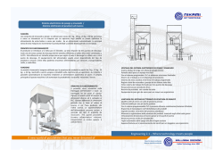
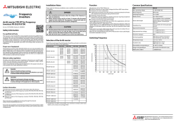


© Copyright 2026