
Hot Air Station
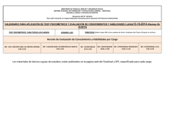
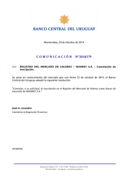
www.jbctools.com
Hot Air Station
Ref. JT-D
Page
English
2
Español
16
w w w.jbctools.com
Packing List
Features
The following items should be included:
JTE Control Unit ............1 unit
Ref. JTE-1D
JTE-2D
JTE-9D
Stand ..................................1 unit
Ref. JT-SD
Heater hose set ............1 unit
Ref. JT-T1A (100V / 120V)
JT-T2A (230V)
USB-B connector
Update the station
software from
the JBC website
Activates the
suction pump
Heating
element
Extractor desk* ..............................................1 unit
Ref. 0008752
Power Cord .....1 unit
Ref. 0009417
(100V/120V)
0009401
(230V)
Manual .............1 unit
Ref. 0016475
JT Accessory set
Ref. 0012332
Extractors*
Ref. E2184
E2064
E2052
Tripod*
Ref. T2050
T2250
Protectors*
Ref. P2220
P2230
P2235
P4000
P4010
Suction Tube*
Ref. 0932330
Suction Cups*
Ref. 0930110
Ø 10 - 0934050 (x3)
Ø 4.7 - 0934070
Nozzles
Ref. JN2015
JN2012
JN2020
www.jbctools.com
Heater Hose set
Ref. JT-T1A (100V/120V)
JT-T2A (230V)
Suction Tube
Ref. 0932330
For tripods
and extractors
Hot Air button
(On / Off)
Another connectable tool:
Precision Heater hose set
Ref: TE-TB
Stand
Ref. JT-SD
Optional:
P-005 Pedal
connection
Power Socket
Fuse
Hot Air Station
Ref. JT-D
* Not supplied with JT-Q stations
2
Equipotential
connection
3
w w w.jbctools.com
Adjustable Stand
Quick Nozzle Changer
Adjust the tool holder angle to suit your work position.
Changing nozzles quickly and safely.
2
1
Turn the tool off
and handle with
care. The heating
element and the
nozzle are still hot.
Operation Modes
1. From the main Menu, select the mode to activate the tool depending on the task.
Stand + Autostart OFF
Stand + Autostart ON
Compatible Nozzles
Pedal*
The JT-TA works with JT nozzles. Find the model that best suits your soldering needs in www.jbctools.com
Press
Press the start/stop button to
blow hot air.
Do not
press
The tool automatically starts
blowing hot air when lifted
from the stand.
2. The tool stops blowing hot air when returned to the stand.
4
Press
Press the Pedal to blow hot
air and release to stop.
*The P-005 Pedal is not
supplied with this station.
See our website.
Straight
Ø mm
Ø mm
Bent
Flat
A x B mm
Ref.
Shape
Size
JN2020
Straight
Ø 8mm
JN8417
Straight
Ø 10mm
JN2015
Bent
Ø 4mm
JN2012
Bent
Ø 6mm
JN6633
Bent
Ø 8mm
JN7637
Flat
10 x 2mm
JN7638
Flat
20 x 2mm
JN7639
Flat
30 x 2mm
In case of a loosely fitting nozzle:
1. Push the nozzle tab inwards with a
screwdriver or flat-nosed pliers.
2. Insert the nozzle into the JT-TA Heater again.
5
w w w.jbctools.com
Protectors & Extractors
Operation
For small components (fig. 1 and 2).
We recommend using the protector + tripod
1
2
Protectors
* Ref. AxB (mm)
For large components (fig. 3 and 4).
We recommend using the extractors
3
* Ref. AxB (mm)
P3353 4,3 x 3
48 P2230 15 x 15
52 E2052 20 X 20
P3786 5,2 x 5,2
60 P4010 17 x 17
64 E2064 20 X 26
P3352 5,2 x 7,5
P4005 18 x 29
80 E2184 24 X 24
P3355 5,2 x 9,5
P4030 18,5 x 18,5
E2068 27 X 27
P3356 6,2 x 4,2
P1068 18,5 x 24
E4020 28,5 X 28,5
P3785 7,2 x 7,2
P2685 28,5 x 28,5
E4015 31,5 X 31,5
P3784 8,2 x 8,2
P4085 31,5 x 31,5
E2084 33 X 33
P4035 9 x 13
P2672 33 x 46
E2100 38 X 38
P4040 9,5 x 19
P4002 50 x 50
P4080 9,5 x 21
P3357 52,5 x 14
32 P2220 10 x 10
P4045 10,5 x 21
P4090 11 x 16
24 P2235 12 x 17
2. Heating
3. Releasing
Position the extractor with the
appropriate suction cup and
press the suction button.
Heat the component.
The component lifts off
automatically when the
solder melts.
4
Extractors
* Ref. AxB (mm)
1. Placing
* Ref. AxB (mm)
E2124 45 X 45
Process Control
Manual Mode
Time to stop
T e m p ºC
Current temperature
Selected temperature
Tripods
* Ref. øC (mm)
45 seconds
Air %
400 85
Current air flow
400ºC Select
Power 70%
% Instant power supplied
to heater
T2050 39
T2250 85
P1249 12 x 23
44 P4000 12,5 x 12,5
Access Menu (pess key 2 seconds) & Confirm Selection
P3354 13,2 x 13,2
P4025 13,5 x 21,5
* Reference Desk
Manual extractor
* Ref. øD (mm)
You can switch between operating modes (Manual Mode / Program Mode) by pressing the
“increase” and “decrease” keys simultaneously for 2 seconds (Only when programs mode is ON).
E2190 7
øD
6
7
w w w.jbctools.com
Program Mode
Menu Screen
Original PIN: 0105
ºC
Graph of selected
program
Program 8
Selected program
Main menu
T e m p ºC
380
Air
100%
Time 125s.
1
2
3
4
Current temperature
Selected air flow
Remaining time
Reset station
Station Settings
Program Settings
Counters
5 Program version
Exit
Decrease program
number
Increase program
number
Station Settings
Program Options
Edit Program
This option allows you to edit or create a program.
First, you must select the program to edit and then modify the points that make up the program.
Each program is composed of 9 points, each point consisting of 3 parameters:
1. Time (seconds)
2. Temperature (°C / °F)
3. Flow rate (%)
You can delete the last point of the program by selecting “-----” in the time parameter.
It should be taken into account that the regulation range permitted by the station is 150-450°C, whereby it is not possible to create temperature ramps between room temperature (Toff) and 150°C.
The station can store up to 25 temperature programs.
The first three programs are edited by JBC as an example.
Copy Program
This option allows you to copy a program.
You must select the program source and its destination (where it will be copied).
Delete Program
This option will allow you to delete a previously selected program.
8
Program Settings
1
2
3
4
Temp unit
Celsius
Maximum temp 4500C
Minimum temp
T OFF
Fix temp
-----
5
6
7
8
Temp Adjust
Max air
Min air
Fix air
+ 00C
100%
10%
-----
9 Time to stop
10 Stand/Pedal
Autostart
11 Beep
120 sec
Stand
OFF
ON
12 Pop up
13 Change PIN
1
2
3
4
ºC
Programs OFF
Edit program
Copy program
Delete program
Edit Program
Select
Program
1
ºC
ON
Back
* Selecting Minimum Temp as
“T OFF”, the air blows at room
temperature.
Edit Program 1
Step
1
Time
30
Temp 300
Air
100
Exit
Counters
1
2
3
Station ON hours
Works hours
Works cycles
0
0
0
Back
9
w w w.jbctools.com
Replacing the Heating Element
Pick & Place (not supplied with JT)
Only perform this operation when the element is cold and the unit is disconnected from the mains.
This tool helps you easily place and remove SMDs of any size thanks to the suction pump.
1. Loosen the screw.
2. Pull the heating element away from the handle.
3. Connect the new heating element, ensuring its pushed all the way in.
4. Tighten the screw.
Pick & Place
Ref. T260-A
Bent Needles Set
Ref. 0861660
Straight Needles Set
Ref. 0901546
Heating Element
Ref. 0014107 (230V)
0014105 (100V / 120V)
Handle
Ref. 0009829
Heating Hose Set
Ref. JT-T1A (100V / 120V)
JT-T2A (230V)
Operation
Choose the needle and the suction cup that best fits the component and start working as follows:
Press the button to
start/stop the suction
Pick & Place
Ref. T260-A
Changing the JT-TA Heater Hose Set
1. Ensure that the tool is turned off.
2. Use a spanner to unscrew the connecting nut.
3. The tube end of the new heater must be inserted
so that the longitudinal rib fits into the groove.
5. Follow the same steps conversely.
1. Suction
2. Release
Once the suction is
activated, cover the
pen hole with your
finger and lift off the
component.
Lift your finger
to release the
component in the
appropriate place.
Maximum working temp: 250ºC (482ºF)
Insert the needle
with the appropriate
cup for a correct
suction process.
10
You should
avoid the needle
protruding from the
lower part.
11
w w w.jbctools.com
Maintenance
Safety
Before carrying out maintenance or storage, always allow the equipment to cool.
It is imperative to follow safety guidelines to prevent electric
shock, injury, fire or explosion.
- Clean the station screen with a glass cleaner or a damp cloth.
- Do not use the units for any purpose other than soldering or rework. Incorrect use may cause fire.
Clean periodically
- Use a damp cloth to clean the casing and the tool. Alcohol can only be used to clean
the metal parts.
- The power cord must be plugged into approved bases. Be sure that it is properly grounded
before use. When unplugging it, hold the plug, not the wire.
- Maintain heating element clean prior to storage in order to avoid its oxidation.
Rusty and dirty surfaces reduce heat transfer.
- Do not work on electrically live parts.
- The tool should be placed in the stand when not in use in order to stop blowing hot air The nozzle, the heating element and the metal part of the stand may still be hot even when the station is turned off. Handle with care, including when adjusting the stand position or changing nozzles.
- Periodically check all cables and tubes.
- Do not leave the appliance unattended when it is on.
- Replace a blown fuse as follows:
- Do not cover the ventilation grills. Heat can cause inflamable products to ignite.
- Use a “non residue” classified flux and avoid contact with skin or eyes to prevent irritation.
Fuse
- Keep your workplace clean and tidy. Wear appropriate protective glasses and gloves when working to avoid personal harm.
Fuse holder
Fuse holder
1. Pull off the fuse holder and remove the
fuse. If necessary use a tool to lever it off.
- Be careful with the fumes produced when soldering.
2. Press the new fuse into the fuse holder and replace it in the station.
- Utmost care must be taken with liquid tin waste which can cause burns.
- This appliance can be used by children over the age of eight and also persons with reduced
physical, sensory or mental capabilities or lack of experience provided that they have been given adequate supervision or instruction concerning use of the appliance and understand the hazards involved. Children must not play with the appliance.
- Maintenance must not be carried out by children unless supervised.
- Replace any defective or damaged pieces. Use original JBC spare parts only.
- Repairs should only be performed by a JBC authorized technical service.
12
13
w w w.jbctools.com
Specifications
JT-1D 120V 50/60Hz. Input fuse 8A. Rated current: 6A. Control Unit model: JTE-1D
JT-2D 230V 50/60Hz. Input fuse 4A. Rated current: 3A. Control Unit model: JTE-2D
JT-9D 100V 50/60Hz. Input fuse 8A. Rated current: 7A. Control Unit model: JTE-9D
- Weight: 6.7 Kg (14.7lb)
- Dimensions: 148 x 184 x 140
- Nominal Power: 700W
- Temperature selection: Room temperature / 150ºC to 450°C (300ºF to 840ºF)
Cool mode: T Off. Used to blow air at room temperature
- Ambient Operating Temperature: 10 to 40ºC (50-104ºF)
- Air flow regulation: 10-50 SLPM
- Vacuum: 30% / 228 mmHg / 9 inHg
- USB connector station-PC
- P-005 Pedal Connection
Complies with CE standards
ESD protected housing “skin effect”
Estación de Aire Caliente
Ref. JT-D
14
15
w w w.jbctools.com
Composición
Características
Los siguientes artículos deben estar incluidos:
JTE Control Unit
Unidad de control JTE .... 1 ud
Ref. JTE-1D
JTE-2D
JTE-9D
Stand
Soporte ....................... 1 unidad
Ref. JT-SD
Heater Hose set
Conjunto calefactor ......... 1 ud
Ref. JT-T1A (100V / 120V)
JT-T2A (230V)
Conector USB-B
Actualice el software
de la estación desde la
web de JBC
Activación de
la bomba de
succión
Elemento
calefactor
JT Accessory set
Conjunto accesorios JT
Ref. 0012332
Extractor desk*
Soporte extractores* ............................... 1 unidad
Ref. 0008752
Power Cord
Cable de red ...... 1 ud
Ref. 0009417
(100V/120V)
0009401
(230V)
Manual ...... 1 unidad
Ref. 0016475
www.jbctools.com
Extractors*
Extractores*
Ref. E2184
E2064
E2052
Tripod*
Trípode*
Ref. T2050
T2250
Protectors*
Protectores*
Ref. P2220
P2230
P2235
P4000
P4010
Suction Tube*
Conjunto conector
aspiración*
Ref. 0932330
Suction Cups*
Conjunto ventosas*
Ref. 0930110
Ø 10 - 0934050 (x3)
Ø 4.7 - 0934070
Nozzles
Boquillas
Ref. JN2015
JN2012
JN2020
Suction Tube
Conjunto conector
aspiración
Ref. 0932330
Para trípodes y
extractores
Heater Hose set
Conjunto calefactor
Ref. JT-T1A (100V/120V)
JT-T2A (230V)
Botón
de aire
caliente
(ON / OFF)
Otra herramienta conectable:
Precision Heater hose set
Conjunto calefactor de precisión
Ref: TE-TB
Stand
Soporte
Ref. JT-SD
Opcional:
Conexión para
el pedal P-005
Entrada
de Red
Fusible
Hot Air Station
Conexión
equipotencial
Ref. JT-D
* No suministrados con las estaciones JT-QD
16
17
w w w.jbctools.com
Soporte ajustable
Cambio rápido de boquillas
Ajuste el soporte de la herramienta para adaptarlo a su posición de trabajo.
Cambio de boquillas rápido y seguro.
2
Desconecte
la herramienta
y manipule
cuidadosamente.
El elemento
calefactor y la
boquilla todavía
están calientes.
1
Modos de funcionamiento
1. Desde el menú principal, seleccione el modo de activar la herramienta en función de la tarea a realizar.
Soporte + Autostart OFF
Pulse
Presione el botón de start/
stop para emitir aire caliente.
Soporte + Autostart ON
No pulse
La herramienta emite aire
caliente automáticamente
cuando se extrae del soporte.
Pulse
Pulse el pedal para emitir aire
caliente y deje de pulsar para
cortar la emisión.
*El pedal P-005 no se
suministra con esta estación.
Consulte nuestra página web.
2. La herramienta deja de emitir aire caliente cuando se devuelve al soporte.
18
Boquillas compatibles
Pedal*
El conjunto calefactor JT-TA trabaja con boquillas JT. Encuentre el modelo que mejor se adapte a sus
necesidades en www.jbctools.com
Ref.
Forma
Tamaño
Recta
Acodada
Plana
Ø mm
Ø mm
A x B mm
JN2020
Recta
Ø 8mm
JN8417
Recta
Ø 10mm
JN2015
Acodada
Ø 4mm
JN2012
Acodada
Ø 6mm
JN6633
Acodada
Ø 8mm
JN7637
Plana
10 x 2mm
JN7638
Plana
20 x 2mm
JN7639
Plana
30 x 2mm
En el caso de que una boquilla no quede del todo ajustada o alineada:
1. Doble la lengüeta de la boquilla hacia aden
tro con la ayuda de un destornillador o unos
alicates planos.
2. Inserte de nuevo la boquilla en el elemento calefactor de su JT-TA.
19
w w w.jbctools.com
Protectores y extractores
Proceso de desoldar
Para desoldar componentes pequeños,
recomendamos que utilice un protector y un
trípode (fig. 1 y 2).
1
2
Protectores
* Ref. AxB (mm)
Para desoldar componentes grandes, recomendamos que utilice los extractores (fig. 3 y 4).
3
* Ref. AxB (mm)
P3353 4,3 x 3
48 P2230 15 x 15
52 E2052 20 X 20
P3786 5,2 x 5,2
60 P4010 17 x 17
64 E2064 20 X 26
P3352 5,2 x 7,5
P4005 18 x 29
80 E2184 24 X 24
P3355 5,2 x 9,5
P4030 18,5 x 18,5
E2068 27 X 27
P3356 6,2 x 4,2
P1068 18,5 x 24
E4020 28,5 X 28,5
P3785 7,2 x 7,2
P2685 28,5 x 28,5
E4015 31,5 X 31,5
P3784 8,2 x 8,2
P4085 31,5 x 31,5
E2084 33 X 33
P4035 9 x 13
P2672 33 x 46
E2100 38 X 38
P4040 9,5 x 19
P4002 50 x 50
P4080 9,5 x 21
P3357 52,5 x 14
32 P2220 10 x 10
P4045 10,5 x 21
P4090 11 x 16
24 P2235 12 x 17
2. Caliente
3. Extraiga
Posicione el extractor con la
ventosa apropiada y pulse
el botón de activación de la
bomba de succión.
Caliente el componente.
El elemento se extrae
automáticamente cuando la
soldadura se funde.
4
Extractores
* Ref. AxB (mm)
1. Coloque
* Ref. AxB (mm)
E2124 45 X 45
Control del proceso
Modo manual
Time to stop
T e m p ºC
Temperatura actual
Temperatura
seleccionada
Trípodes
* Ref. øC (mm)
45 seconds
Air %
400 85
Caudal de aire actual
400ºC Select
Power 70%
% Potencia instantánea
suministrada al calefactor
T2050 39
T2250 85
P1249 12 x 23
44 P4000 12,5 x 12,5
Menú de acceso
(pulse 2 segundos)
y
Confirmar selección
P3354 13,2 x 13,2
P4025 13,5 x 21,5
* Escritorio de referencia
Extractor manual
* Ref. øD (mm)
E2190 7
øD
20
Se pueden modificar los modos de funcionamiento (Modo manual / Modo de programa) pulsando
las teclas de “incrementar” y “reducir” simultáneamente durante 2 segundos. (Sólo con el modo
de programa activado).
21
w w w.jbctools.com
Modo de programa
Pantalla de menú
PIN original: 0105
ºC
Gráfica del programa
seleccionado
Program 8
Programa seleccionado
Main menu
T e m p ºC
380
Air
100%
Time 125s.
1
2
3
4
Temperatura actual
Caudal de aire selecc.
Tiempo restante
Reset station
Station Settings
Program Settings
Counters
5 Program version
Exit
Reducir número
de programa
Incrementar número
de programa
Station Settings
Opciones de programa
Editar programa
Esta opción le permite editar o crear un programa.
En primer lugar, debe seleccionar el programa a editar, y entonces, modificar los puntos que lo
forman.
Cada programa consta de 9 puntos, cada uno de ellos basado en tres parámetros:
1. Tiempo (segundos)
2. Temperatura (°C / °F)
3. Caudal de aire (%)
Para eliminar el último punto de un programa, debe seleccionar “-----” en el parámetro de tiempo.
Además, debe tenerse en cuenta que el rango de temperatura de la estación es de entre 150ºC
y 450ºC, por lo tanto no es posible crear rampas de temperatura entre la temperatura ambiente
(T OFF), y 150ºC.
La estación puede almacenar hasta 25 programas de temperatura.
Los tres primeros programas son editados por JBC como ejemplo.
Copiar programa
Esta opción le permite copiar un programa.
Primero deberá seleccionar el origen del mismo, y después el destino donde será copiado.
Eliminar programa
Esta opción le permitirá eliminar un programa previamente seleccionado.
22
Program Settings
1
2
3
4
Temp unit
Celsius
Maximum temp 4500C
Minimum temp
T OFF
Fix temp
-----
5
6
7
8
Temp Adjust
Max air
Min air
Fix air
+ 00C
100%
10%
-----
9 Time to stop
10 Stand/Pedal
Autostart
11 Beep
120 sec
Stand
OFF
ON
12 Pop up
13 Change PIN
1
2
3
4
ºC
Programs OFF
Edit program
Copy program
Delete program
Edit Program
Select
Program
1
ºC
ON
Back
* Seleccionar “T OFF” como
temperatura mínima habilita el
soplado de aire a temperatura
ambiente.
Edit Program 1
Step
1
Time
30
Temp 300
Air
100
Exit
Counters
1
2
3
Station ON hours
Works hours
Works cycles
0
0
0
Back
23
w w w.jbctools.com
Cambio del elemento calefactor
Pick & Place (no se suministra con las estaciones JT-D)
Realice únicamente esta operación cuando el elemento calefactor esté frío y la unidad de control
desconectada.
Esta herramienta le ayuda fácilmente a posicionar y extraer componentes SMD de cualquier tamaño
por medio de la bomba de succión.
1. Afloje el tornillo.
2. Extraiga el elemento calefactor del mango.
3. Conecte el nuevo elemento calefactor, asegurando que quede totalmente insertado.
4. Apriete el tornillo.
Pick & Place
Ref. T260-A
Bent Needles Set
Conjunto de agujas dobladas
Ref. 0861660
Straight Needles Set
Conjunto de agujas rectas
Ref. 0901546
Elemento calefactor
Ref. 0014107 (230V)
0014105 (100V / 120V)
Mango
Ref. 0009829
Conjunto calefactor
Ref. JT-T1A (100V / 120V)
JT-T2A (230V)
Funcionamiento
Escoja la aguja y la ventosa que mejor se adapte al componente que desee desoldar y comience a
trabajar de la siguiente manera:
Pulse el botón para
empezar/terminar la
succión
Pick & Place
Ref. T260-A
Cambio del conjunto calefactor JT-TA
1. Asegúrese que la herramienta esté desconectada.
2. Utilice una llave inglesa para desenroscar la tuerca de conexión.
3. El extremo del tubo del nuevo calefactor debe insertarse de manera que el nervio
longitudinal encaje en la ranura.
4. Siga los mismos pasos a la inversa.
1. Succione
2. Extraiga
Una vez que la
succión esté
activada, cubra el
orificio del lápiz con
su dedo y extraiga
el componente.
Quite el dedo del
orificio para dejar el
componente en el
lugar deseado.
Temperatura máx. de trabajo: 250ºC (482ºF)
Inserte la aguja
con la ventosa
adecuada para una
correcta succión.
24
Debe evitar que la
aguja sobresalga
por la parte inferior
de la ventosa.
25
w w w.jbctools.com
Mantenimiento
Seguridad
Antes de almacenar o de su mantenimiento, desconecte el equipo y déjelo enfriar.
- Use un paño húmedo para limpiar
la pantalla del equipo, la carcasa y la herramienta. Solamente utilice alcohol
para las partes metálicas.
Es necesario cumplir estas normas de seguridad para prevenir cualquier
choque eléctrico, heridas, fuego o explosiones.
Limpie periódicamente
- No utilice el equipo para otros fines que no sea la soldadura o reparación. El uso incorrecto puede causar fuego.
- Mantenga el elemento calefactor limpio antes de almacenar para evitar la oxidación de la punta de la herramienta.
Superficies oxidadas o sucias reducirán la transferencia de calor a la soldadura.
- El cable de red debe enchufarse en bases homologadas. Asegúrese de que está conectado a tierra correctamente antes de su uso. Al desenchufarlo, tire del conector, no del cable.
- La herramienta debe permanecer en el soporte cuando no está en uso con el fin de activar el modo de Sleep. El cartucho, la parte metálica de la herramienta y el soporte puede estar caliente incluso cuando la estación está apagada. Manipule con cuidado, incluso cuando ajuste la posición del soporte.
- Revise periódicamente la conexión de cables y/o tubos.
- Cambie un fusible fundido de acuerdo con las siguientes instrucciones:
- No deje el aparato desatendido cuando esté en funcionamiento.
Fusible
- No cubra las rejillas de ventilación. El calor puede causar que los productos inflamables se enciendan.
- Utilice un flux clasificado como “non residue” y evite el contacto con la piel y los ojos para evitar que se irriten.
Portafusible
- Tenga cuidado con el humo producido al trabajar.
Portafusible
- Mantenga su lugar de trabajo limpio y ordenado. Use gafas y guantes de protección adecuados.
Así evitará cualquier daño.
1. Tire del portafusible para retirar el fusible.
Si lo precisa, utilice una pequeña palanca.
2. Sustituya el fusible y coloque de nuevo el
portafusibles en su sitio.
- Cambie cualquier pieza defectuosa o dañada. Utilice solamente recambios originales de JBC.
- Cualquier reparación sólo se podrá realizar por un servicio técnico oficial JBC.
26
- Tenga cuidado con los restos de estaño líquido. En contacto con la piel, puede causar quemaduras.
- Este aparato puede ser utilizado por personas a partir de 8 años y también por aquellas personas con movilidad reducida o capacidades físicas, sensoriales o mentales limitadas o con falta de experiencia y conocimientos siempre y cuando reciban supervisión o instrucciones relativas al uso del aparato de una manera segura y entiendan los riesgos que implica. Los niños no deben jugar con el aparato.
27
w w w.jbctools.com
Especificaciones técnicas
JT-1D 120V 50/60Hz. Fusible de entrada: 8A. Corriente nominal: 6A. Unidad de control: JTE-1D
JT-2D 230V 50/60Hz. Fusible de entrada: 4A. Corriente nominal: 3A. Unidad de control: JTE-2D
JT-9D 100V 50/60Hz. Fusible de entrada: 8A. Corriente nominal: 7A. Unidad de control: JTE-9D
- Peso: 6,7 Kg (14.7lb)
- Dimensiones: 148 x 184 x 140 mm
- Potencia nominal: 700W
- Selección de temperatura: Temperatura ambiente / 150-450°C (300-840ºF)
Modo de enfriamiento: T OFF. Utilizado para emitir aire a temperatura ambiente
- Temperatura ambiente de trabajo: 10-40ºC (50-104ºF)
- Regulación de caudal de aire : 10-50 SLPM
- Vacío: 30% / 228 mmHg / 9 inHg
- Conector USB estación-PC
- Conexión de pedal P-005
Cumple con las normativas CE
Seguridad ESD
28
29
w w w.jbctools.com
Exploded View · Despiece
30
31
Warranty
JBC’s 2 year warranty covers
this equipment against all
manufacturing defects, including
the replacement of defective
parts and labour.
Warranty does not cover product
wear due to use or mis-use.
In order for the warranty to
be valid, equipment must be
returned, postage paid, to the
dealer where it was purchased.
Garantía
Esta garantía de 2 años cubre
este equipo contra cualquier
defecto de fabricación,
incluyendo la sustitución de partes
defectuosas y mano de obra.
La garantía no cubre el desgaste
del producto por uso o mal uso.
Para que esta garantía sea válida,
el equipo debe ser devuelto, a
portes pagados, al distribuidor
donde se compró.
This product should not be thrown in the garbage.
In accordance with the European directive 2012/19/EU, electronic equipment at the end of their life
must be collected and returned to an authorized recycling facility.
www.jbctools.com
0016475-0116
Este producto no debe desecharse en la basura.
De acuerdo a la directiva europea 2012/19/UE, los equipos electrónicos al final de su vida se
deberán recoger y trasladar a una planta de reciclaje autorizada.

© Copyright 2026