
Dear SpaceX Hyperloop Pod Competition Designers and
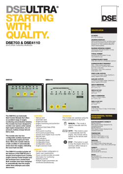
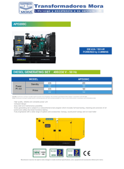
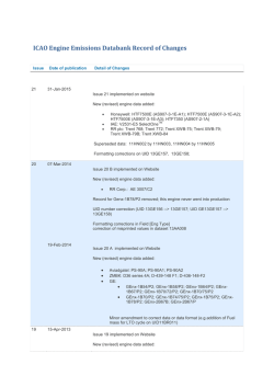
Dear SpaceX Hyperloop Pod Competition Designers and FellowSuppliers: This is an exciting time! On October 7, 2015, SpaceX released its draft specifications for the Hyperloop Pod Competition and we are pleased to announce that SpaceX is accommodating our proprietary Magnetic Field Architecture (MFA™) technology in those draft specifications. As a result, Arx Pax will soon be taking orders for hover engines for use in the pod competition. One year ago, Arx Pax introduced the world’s first real hoverboard as a proof of concept for its MFA technology. The highly successful launch of the Hendo Hoverboard led to accolades such as one of Time Magazine’s top inventions of the year and focused a spotlight on the many applications of MFA technology that we believe will ultimately change the way people work, play, and live. What follows in this document is our draft specification and introduction to our technology as well as details about how to incorporate it into a successful pod design. SpaceX has opened a comment period for its draft specifications which is scheduled to end October 14th. Participants will have until that date to comment on and propose changes to the current test track’s design. Likewise, we want to give all participants the opportunity to get to know our technology and better understand why we believe our hover engines and related technology are ideal for this competition and ultimately for realworld application. So, in the spirit of collaboration, we are providing participants with this draft specification to give us the feedback you think is important and let us know what you need to see in our final specifications that would be the most helpful for your success. We will close our call for comments on October 18 and provide our final specifications after October 20, 2015. Please submit your comments and questions directly to: [email protected] . And also remember to provide your comments and other feedback to SpaceX showing your support for MFA! Hover a Pod! The Arx Pax Team DRAFT SPECIFICATIONS Hover Engine Design Details for SpaceX Hyperloop Pod Competition Congratulations on entering the SpaceX Hyperloop Pod Competition! This competition supports several modalities of transport as defined by SpaceX. At Arx Pax we have developed a new magnetic levitation technology based on our proprietary Magnetic Field Architecture (MFA™). We believe our revolutionary technology solves all of the preexisting challenges that have prevented Hyperloop platforms from being constructed in the past. HOVERING = Levitation + Propulsion + Control + Braking Now, you can simultaneously solve levitation, propulsion, and guidance/control with one system that is readily controlled through software and related mechanical systems. Our hover engine provides that solution: levitation, propulsion, control and braking to the vehicle designer in a granular architecture that allows for maximum design flexibility. In other words, this is a new fundamental technology that will help make the Hyperloop a reality. BENEFITS MFA provides a quantum effectiveness benefit over traditional airbearing systems at a fraction of the cost of traditional maglev transport. And, unlike traditional maglev, all system control is done on the vehicle, removing the need for an expensive and complex active track system. MFA offers designers flexibility in system architecture, as our engines can be placed anywhere under a vehicle and can be independently programmed to optimize vehicle performance. Further, MFA can work easily in systems that require banked turns, which allows for maximum routing flexibility in the eventual passengerbased Hyperloop system. We’re big supporters of the Hyperloop and are fully committed to seeing it built. We’ve built the technology that can make it happen. And we can’t wait to work with you to build the pod that will make transportation history. Page 2 of 11 ArxPax.com DRAFT SPECIFICATIONS Introduction The Arx Pax HE3.0 Hover Engine has been designed and developed for the half scale, SpaceX Hyperloop competition. The engine is designed with Arx Pax’s patented MFA technology which efficiently shapes and controls magnetic fields. A hover engine works by inducing eddy currents in a conductive substrate by providing a highly concentrated, specifically designed primary magnetic field. The induced eddy currents result in secondary repulsive magnetic fields which generate lift. Each hover engine consists of an electric motor, a motor controller and a STARM™. A STARM is the Arx Pax MFA hover component. Each hover engine ships with a shroud which covers the engine and provides additional safety for the engine itself and for the user. Finally, the system comes with a mounting bracket intended to simplify installation. The motor controller is typically electronically disposed between the electric motor and a DC electric power source. It controls the power reaching the electric motor by a software interface that will allow the user to modify parameters such as current, voltage, and timing. Fig. 1 shows a rendering of the Arx Pax HE 3.0 Hover Engine. The top of the system (in blue) is the cover of the Motor Controller. Red and Grey wires connect to the Motor Assembly and the STARM, both of which are located inside the shroud (shown in white). Refer below for dimension data. Page 3 of 11 ArxPax.com DRAFT SPECIFICATIONS The orientation of a hover engine relative to the conductive surface generates thrust, i.e. forces parallel to the subtrack. The net force from the a pod’s hover engines can be controlled to propel the vehicle in any direction, forward or backward, sideways or on a diagonal. More importantly (and unlike wheels) they can be made to turn or rotate 360 degrees while moving in any direction. Teams will be responsible for designing their own mechanical and software systems to control the lift and thrust forces of their pod’s engines. Onboard DC power should be planned for. See data below. Hover Engines: At the heart of Arx Pax's proprietary MFA technology are its hover engines. Arx Pax will provide hover engines to all participants. A discounted uniform cost structure is below. All pricing and data are provided for the HE3.0 Hover Engine to be confirmed after final tube specs are released by SpaceX. While future custom models may be developed by Arx Pax through a specific engagement it is our intent to provide only one type of engine for the SpaceX Pod Competition to ensure a level playing field. Please note that the minimum order size is for four (4) hover engines. Additional hover engines can be ordered in groups of two (2). Some Pod configurations may require more hover engines depending on overall mass, and other pod specific design parameters. Commercial and Technical Support: Arx Pax wants all participants to succeed in bringing their vision to fruition. In order to facilitate the incorporation of Arx Pax's technology and products into their designs, Arx Pax will provide and maintain a FAQ list and technical support necessary for the participants to achieve their goals. Page 4 of 11 ArxPax.com DRAFT SPECIFICATIONS Pricing All competition participants can purchase Arx Pax’s hover engine technology, which includes a license for use solely in the pod competition and for their ongoing research. Participants will be restricted from using the technology for commercial purposes. We are offering specially discounted pricing for universities and nonprofits. The costs are as follows: Basic 4 Pack, HE3.0 Hover Engines: $TBD Additional 2 HE3.0 Hover Engines: $TBD Hover Engine Safety The HE3.0 Hover Engine contains strong permanent magnets. Therefore, precaution should be used when using ferromagnetic parts, (steel, iron, nickel, etc.) including control hardware, support components and tools. Likewise, parts made from conductive materials may heat up if they are in close proximity (less than 10 cm) below the hover engine during operation. The STARM cover should not be removed under any circumstances and a hover engine should not be operated without a cover. The hover engines operate in a high current range (especially if loaded) so proper safety cutoffs should be established for testing and operation. Specifications for a single HE3.0 Hover Engine All data is based on a single HE3.0 Hover Engine operating in a stationary position over a conductive surface of 9.5mm thickness of copper. The competition tube specifications will utilize 6101T64 grade Aluminum subtracks at roughly 1” thickness. The performance of our device in the competition tube will be largely equivalent to the specifications list below: Page 5 of 11 ArxPax.com DRAFT SPECIFICATIONS Maximum Nominal Lift : 68kg (150lbs). Rated Lift : 55kg (120lbs). Engine Weight (excluding controller) : 7kg (15lbs). Rated Payload : 48kg (105lbs). Approximate Engine Dimensions : Diameter 266mm (10.5in), Height 76mm (3.0in). Current Draw : This engine is expected to operate in the range of 70W per kilogram lifted. For example, at Rated Input Voltage of 39V, the system is expected to draw 1.8A per kg or 0.82A per pound payload. Actual current draw is designspecific and varies with payload and voltage, an example of which is noted in Figure 2 . Hover Height: As measured from engine bottom, 20mm (.79in) 5mm (.2in) depending on payload. Please refer to Figure 2 . Motor Controller Dimensions : Length 139mm, Width 126mm, Height 58mm. See datasheet linked below for other dimensions. Motor Controller Maximum Current: 150A absolute peak, 100A 1min period, 50A Continuous. Motor Controller Maximum Voltage : 72V. Motor Controller Spec Sheet and Software: Accelerated Systems Cadmium Series BAC 200072100 Figure 2 Page 6 of 11 ArxPax.com DRAFT SPECIFICATIONS HE3.0 Hover Engine Performance The above graph shows the relationship of power consumption and hover height as the mass of the system payload increases, based on 70W/Kg. The trendline provides an approximation of a power/lift ratio for the HE3.0 Hover Engine. In general, power consumption increases and hover height decreases with additional load. This graph gives a representation of typical hover engine performance. Individual performance will vary based on unique system designs. Arx Pax has designed and built hover engines to optimize characteristics such as lift, lift/drag ratio, propulsion, efficiency, etc. Arx Pax has demonstrated engines with efficiency better than 33W/kg. Interestingly, like the passive Inductrack maglev system, once a critical translational speed has been reached (approximately 10m/s) the power requirements drop dramatically. Notes on designing with the Arx Pax HE3.0 Hover Engine 1. There is an inverse relationship between hover height and payload capacity 2. Begin with the desired hover height for system design. 3. To achieve hover height, use the lift value associated with it as provided here: Hover Height (mm) Payload Lift Value (Kg) 5 41 10 23 15 13 20 8 4. Estimate the total pod mass and divide by the payload capacity for planned hover height. This provides an estimate of the number of hover engines needed. 5. Additional hover engines may be required if system weight is not evenly distributed. Page 7 of 11 ArxPax.com DRAFT SPECIFICATIONS 6. When actuated, some of the hover engine’s lift vector can be converted into propulsion. Said actuation can provide directional control as well as braking. Depending on the magnitude of actuation, the lift provided by the hover engine can be diminished. 7. To optimize performance, additional hover engines may be deployed for propulsion, control and/or stabilization of the system. Propulsion and Control Photos, videos and other design information will be available shortly. Please go to http://arxpax.com/technology/transportation/ for updates (coming soon). In general, thrust generated from a single hover engine depends on its tilt orientation relative to the hover surface. A horizontal position is neutral. As a hover engine is tilted near the hover surface the closer portion generates more traction than the distant portion, generating thrust. The direction of the thrust is parallel to the axis of tilt ( see Figure 3 ). Directional control will therefore involve mechanical and software systems that can control rotational speed, spin direction, and actuation of the STARM relative to the hover surface. In practice, very little actuation is required in order to generate force in a properly designed system substantial forces can be generated with as little as 2 degrees of actuation. Pod competition designers can generate custom actuation schemes that differentiate their endsystem performance. Figure 3 Page 8 of 11 ArxPax.com DRAFT SPECIFICATIONS Fig. 3 depicts the generation of a directional force to effect control and propulsion of a hover engine relative to a conductive surface. A depicts the device being tilted along its axis of rotation. With the direction of rotation in a counterclockwise direction as shown in B , the hover engine will move in direction C . Page 9 of 11 ArxPax.com DRAFT SPECIFICATIONS Appendix 1 Mounting Hole Drawing for HE3.0 Hover Engine For designers who would like to mount a hover engine directly to their systems without using the attached mounting bracket, please refer to this drawing. Appendix 2 Page 10 of 11 ArxPax.com DRAFT SPECIFICATIONS Notes on Hover Material for Lab Environments Hover efficiency is a function of surface material conductivity %IACS as represented below. Minimum Hover surface for HE3.0 Hover Engine : 1100grade Aluminum (%IACS 57.00), 7mm thickness 110grade Copper (%IACS 100.00), 4mm thickness 6061grade Aluminum (%IACS 40.00), 10mm thickness Recommended Hover surface for HE3.0 Hover Engine : 1100grade Aluminum , 20mm thickness 110grade Copper , 10mm thickness 6061grade Aluminum , 30mm thickness Note: SpaceX Tube plans for .8 inches of 6101T64 Aluminum (%IACS 60.00) Minimum hover surface is defined as the minimum surface characteristics required in order to achieve hover with NO payload in a lab environment. Recommended hover surface allows for better efficiencies and moderate payloads along with better thermal performance for the material and components. As perengine payload increases the amount of material needed to support efficient performance may increase as well. In a lab environment copper may be stacked in thin sheets to achieve the same performance as a thicker piece of copper. For example, we often stack 3 1/8” sheets of 110grade Cu for our system testing. However, the same is not true for Aluminum, as Al sheets typically develop an oxide layer which can act as an electrical insulator and will affect performance of the hover engine. Other conductive materials can also be used in proportional amounts determined by referencing the International Annealed Copper Standard of Conductivity (%IACS). Page 11 of 11 ArxPax.com
© Copyright 2026