
Manual montaje KIT DPS J3C-140/300
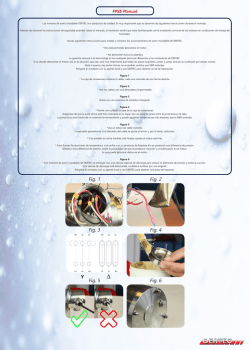
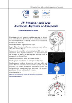
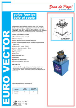
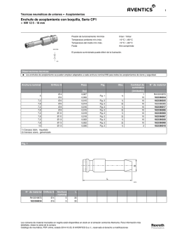
INSTRUCCIONES MONTAJE KIT “DPS 2005” J3C-140/300
1– Tapa
2– Electrónica posicionador
3– Columna hexagonal
4– Tornillo
5– Esquema eléctrico
6– Etiqueta nº serie del KIT
7– Formulario a rellenar
1
KDJ3C2V001
1
TORNILLO / SCREW
2
3
5
6
7
3
4
6
ZOOM
5
2
4
7
ELECTRÓNCA
PCB DPS 2005
8
MUY IMPORTANTE!!!!
AGUJERO
ENGRANAJE
PARA CONVERTIR UN ACTUADOR ELECTRICO STANDARD J3C (ON-OFF) A ACTUADOR CON POSICIONADOR PROCEDER DE LA SIGUIENTE MANERA:
GEAR HOLE
La unidad debe ser desconectada de cualquier conexión a la red eléctrica o de señal antes de instalar el Kit.
1: Desatornillar el tornillo de sujeción del volante y extraerlo (Fig.1).
2: Desatornillar los 8 tornillos de unión entre la tapa y el cuerpo (Fig.2).
3: Retirar cuidadosamente la tapa. (Fig.3).
4: Retirar cuidadosamente el indicador visual de posición (Fig.4).
5: Desatornillar el tornillo situado en la chapa metálica del actuador (Fig.5).
6: Fijar la columna hexagonal (3) a la chapa del actuador (Fig.6).
7: Montar la electrónica posicionador DPS2005 (2), haciendo coincidir el perfil del engranaje con el del eje central . Introducir el engranaje en el eje hasta que el conector de la electrónica posicionador DPS2005 esté conectado
al conector de la electrónica del actuador (Fig 7).
8: Fijar con el tornillo (4), la electrónica posicionador DPS2005 (2) a la columna hexagonal (3) (Fig.8).
9: Insertar el conector de 3 pins de la tapa (corriente), a la base conector (1) (Fig.9) e insertar el conector de toma
tierra (cable amarillo/verde) en la base conector (2) (Fig.9).
10: Insertar el conector de 4 pins de la tapa (señal), a un lado o a otro de la base conector (3), dependiendo de si
desea trabajar en la posición 0-10V o en la de 4-20mA (Fig.9).
11: Insertar el conector de 5 pins de la tapa (confirmación), en la base conector (4) (Fig.9).
12: Insertar cuidadosamente el indicador visual de posición haciendo coincidir el perfil del indicador con el del eje
(Fig.10).
13: Montar la tapa, con cuidado de no aprisionar los cables (Fig.11).
14: Atornillar los 8 tornillos de unión entre la tapa y el cuerpo (Fig.12).
15: Montar el volante al eje y fijarlo mediante el tornillo (Fig.13).
16: Sustituir el esquema adjunto al actuador por el suministrado en el KIT (5).
17: Pegar la etiqueta nº serie del KIT (6) en el cuerpo del actuador.
18: Rellenar el formulario (7) y enviarlo por e-mail o por fax.
El actuador esta listo para trabajar.
COMO HACER UN AUTOAJUSTE EXTERNO DEL POSICIONADOR:
1º Hacer un cruce entre el PIN tierra y el PIN 1 en la base de conector central de la tapa.
2º Alimentar voltaje al conector gris del actuador.
3º Desconectar el cruce de la base del conector central.
El actuador realizará una maniobra completa haciendo un autoajuste en el posicionador.
ZOOM
EJE
ZOOM
SHAFT
9
0/10 V
1
3
1
2
13
4
2
4
11
10
TORNILLO / SCREW
4/20mA
3
12
14
PEGAR ETIQUETA
RELLENAR Y ENVIAR EL
FORMULARIO
COMPLETE THIS FORM
AND SEND IT
CAMBIAR LA ETIQUETA
CHANGE THE LABEL
KIT “DPS 2005” POSITIONER ASSEMBLY INSTRUCTIONS J3C-140/300
1– Cover
2– Positioner PCB
3– Hexagonal column
4– Screw
5– Label electricl diagramo
6– Label serial number
7– Form to fill in.
1
1
TORNILLO / SCREW
2
3
5
6
7
3
4
6
5
ZOOM
2
4
VERY IMPORTANT!!!! PLEASE FOLLOW THE INSTRUCTIONS STEP BY STEP
7
ELECTRÓNCA
PCB DPS 2005
8
TO CONVERT A STANDARD (ON-OFF) J3C ELECTRIC ACTUATOR INTO A MODULATING FUNCTION
WITH POSITIONER, PROCEED AS FOLLOWS:
The unit must be disconnected from any electrical power or signal before installing.
1: Remove the screw from the top of the hand wheel (Fig.1).
2: Remove the 8 cover screws (Fig.2).
3: Carefully lift the cover (Fig.3).
4: Carefully remove the position indicator (Fig.4).
5: Remove the screw from the base plate (Fig.5).
6: Fix the hexagonal column (3) on the base plate (Fig.6).
7: Mount the DPS2005 positioner PCB (2), matching the flat side of the shaft with the flat side of the gear (Fig. 7).
Press the DPS2005 positioner PCB (2) along the shaft until the DPS2005 positioner PCB connector is plugged in
the actuator PCB (Fig. 7).
8: Fix the DPS2005 positioner PCB (2) to the hexagonal column (3) with the screw (4) (Fig.8).
9: Connect the 3 pin power supply plug to the socked (1) (Fig.9) on the actuator PCB, then, connect the earth connector (yellow/green) cable into the socked (2) (Fig.9).
10: Connect the 4 pin (control signal) plug into the corresponding socked 4/20mA or 0/10V (3) (Fig.9).
11: Connect the 5 pin (confirmation) plug into the socked (4) (Fig.9).
12: Carefully insert the position indicator, matching its flat sides with the flat sides of the shaft (Fig.10).
13: Carefully mount the cover, minding the cables not to be pressed between the cover and de body of the actuator.
(Fig.11).
14: Fix the cover to the body by using the before mentioned 8 screws (Fig.12).
15: Mount the hand wheel on the shaft and fix it by using the screw (Fig.13).
16: Remove the wiring diagram of the actuator and put the one supplied together with the DPS 2005 KIT (5).
17: Stick the label with the serial number, supplied with the DPS 2005 KIT on the body of the actuator.
18: Fill in the blanks of the form and send it back to the manufacturer, either by mail or by fax.
THE ACTUATOR IS READY TO WORK.
HOW TO MAKE AN EXTERNAL SELF-ADJUSTMENT OF THE POSITIONER:
1º Connect a cable between PIN 1 (on the left side) and Earth PIN (on the bottom) in the socket, located in
the center of the cover.
2º Connect the grey connector to the power supply.
3º Remove the cable between PIN 1 and the Earth PIN from point 1º
The actuator will make a complete maneuver and a self adjustment of the positioner.
ZOOM
AGUJERO
GRANAJE
GEAR HOLE
EJE
ZOOM
SHAFT
9
0/10 V
1
3
1
2
13
4
2
4
11
10
TORNILLO / SCREW
4/20mA
3
12
14
PEGAR ETIQUETA
RELLENAR Y ENVIAR EL
FORMULARIO
COMPLETE THIS FORM
AND SEND IT
CAMBIAR LA ETIQUETA
CHANGE THE LABEL


© Copyright 2026