
FIRST Team 5526
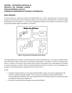
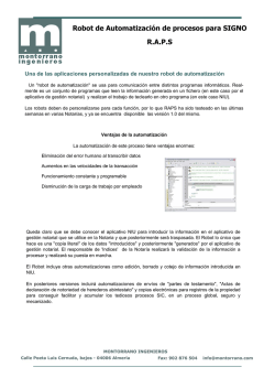
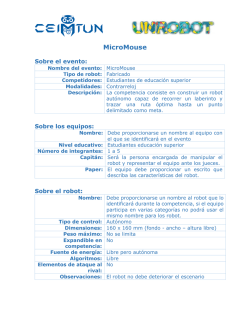
Torreón, Coahuila México
FIRST Team 5526
Season 2015
Excellence for Life through Science and Technology
Colegio Americano de Torreón
2015
tCATs 5526
Colegio Americano de
Torreón
[MANUAL:
SAFETY/SEGURIDAD]
Captain: Itzel Trejo
SAFETY FIRST
In the tCats 5526 workshop...
At tCats 5526 we consider safety a priority for everyone. At the start of the season, before handling
equipment, we gave all of our members a workshop on safety using the STOP approach which
was offered by Peñoles. This approach emphasized the need to stop, analyze, and reduce the risk
factors in the work area. After the workshop, we also had our mentors teach the team members the
proper way to use the equipment in the workshop.
Safety measures
One of the basic safety measures we have at the workshop is having a first aid kit properly labeled
and visible to everyone in case of emergencies. We also follow the safety regulations such as
having an emergency exit and a fire extinguisher, properly labeled as well. We emphasize the
need to clean up the workshop after a work session between our team members. This helps to
keep the risk factors to a minimum level and also maintains an organized and tidy work area.
Safety Rules
Basics
1. Keep your anti-cut gloves on at all times.
2. Keep your protection glasses on at all times.
3. Long sleeved shirt has to be worn at all times.
4. Everybody has to use closed shoes.
5. Do not get close to any of the sharp/automatic tools without a supervisor or proper knowledge
of use.
6. Do not throw objects around in the workshop.
7. When someone is welding, please stay away from the area and avoid at all costs to see the
light emitted from the process, as it may be harmful for your eyes.
8. Do not leave any sharp objects unattended and/or in places where someone may step on them
and/or cut themselves.
9. Leave all personal belongings inside the lockers or in any of the small tables close to the walls
by the entrance.
10. If the noise begins to hurt your ears, please use your earplugs to avoid damage to your
hearing.
11. Be careful with liquids. Do not bring them close to the electrical components as they might
cause a short circuit if they are spilled.
12. After cutting a piece, round the edges by using a file to avoid having accidents when handling
the piece.
13. Make sure no pieces are left on the ground, as they may become hazardous objects if left
unattended.
14. Do not play around with any of the tools.
15. Keep the work area clean.
16. When all work in the workshop is done, you must help put all the tools back into their proper
place for ease of use and to emphasize on points 8, 11, and 13.
Mechanics
1. Be careful when cutting do not look directly at the lights.
2. Disconnect the electrical tools after usage.
3. Mind your surroundings when operating tools
Electronics
1. Don’t move the cables while the robot is on
2. Cut the cables away from the components of the robot to avoid any pieces of wire coming in
contact with the pins.
3. Don’t leave any kind of wire without electrical tape
4. Be careful connecting the right cables in their specific poles
5. Don’t touch the pins at any circumstances
Programming
1. Don’t have liquids near the work area
2. Don’t download or use illegal software
3. Don't enable the robot when people are still working on/around it
4. Be ready to disable the robot at anytime you are running the code on it
SEGURIDAD FIRST
En el taller de tCats 5526...
En tCats 5526 consideramos a la seguridad como una prioridad para todos. Al comienzo de la
temporada, antes de usar las herramientas y el equipo, le dimos a todos nuestros miembros un
curso de seguridad usando el método STOP, el cual fue ofrecido por Peñoles. Este método
enfatiza la necesidad de detenerlos, analizar y reducir los factores de riesgo en el área de trabajo.
Después del curso, hubo también clases impartidas por nuestros mentores sobre la manera
correcta de usar el equipo de trabajo.
Medidas de Seguridad
Una de las medidas de seguridad básicas que tenemos en el taller de tCats 5526 es tener un
botiquín de emergencias adecuadamente marcado y visible para todos en caso de una situación
en el que tenga que ser usado. También seguimos las regulaciones de seguridad como tener una
salida de emergencia y un extintor de fuegos, los cuales están apropiadamente marcados.
Enfatizamos la necesidad de limpiar el taller después de una sesión de trabajo entre los miembros
de nuestro equipo. Esto ayuda mantener los factores de riesgo en un nivel mínimo además de
mantener un área de trabajo limpia y organizada.
Reglas de Seguridad
Básicas
1. Mantén tus guantes anti-corte puestos en todo momento.
1. Mantén tus lentes de seguridad puestos en todo momento.
2. Usar playera de manga larga en todo momento.
3. Usar zapatos cerrados.
4. No acercarse a ninguna herramienta sin un supervisor o conocimiento de uso.
5. No lanzar objetos en el taller.
6. Cuando alguien este soldando, mantente alejado del área y evita ver la luz emitida en el
proceso, porque es dañina para la vista.
7. No dejar objetos afilados sin atender y/o en lugares donde alguien los pueda pisar o cortarse
con ellos.
8. Dejar todos los objetos personales dentro de los casilleros para evitar accidentes.
9. Si el ruido empieza a lastimar tus oídos, usa tus tapones de oídos para evitar lastimarte.
10. Ser cuidadoso con líquidos. No traerlos cerca de los componentes eléctricos porque pueden
causar un corto circuito si se caen.
11. Después de cortar una pieza, redondea las esquinas usando una lima para evitar accidentes.
12. Asegurarse de no dejar piezas en el suelo, ya que se pueden volver objetos peligrosos si se
dejan desatendidos.
13. No jugar con las herramientas.
14. Mantener el área de trabajo limpia y ordenada.
15. Cuando todo el trabajo en el taller ha terminado, ayudar a poner todas las herramientas en su
lugar y enfatizar los puntos 8, 11 y 13.
Mecánica
1. Ser cuidadoso al cortar piezas para no ver la luz emitida por la maquina.
2. Desconectar las herramientas eléctricas después de usarlas.
3. Estar atento de tus alrededores cuando usas herramientas.
Electrónica
1. No mover los cables mientras el robot este encendido.
2. Cortar los cables alejado de los componentes del robot para evitar que algún pedazo de cable
entre en contacto con los pines.
3.No dejar ningún tipo de cable sin protegerlo con cinta aislante.
4. Asegurarse de conectar los cables correctos a sus polos específicos.
5. No tocar los pines electrónicos.
Programación
1. No tener liquido cerca del área de trabajo.
2. No descargar o usar software ilegal.
3. No habilitar el robot cuando hay personas cerca o trabajando en el.
4. Estar listo para apagar el robot en cualquier momento cuando estés corriendo código en el robot.
2015
tCATs 5526
Colegio Americano de
Torreón
[MECHANICS MANUAL]
Captain: Jorge Clorio
Subcaptain: René Nieto
Workshop rules
General Rules
1. Always wear your gloves
2. Always wear your glasses
3. Use long sleeved shirt
4. Wear closed shoes
5. No playing
6. Clean your work area
7. Only use machinery you know how to operate
8. Don’t threaten the people with the tools
9. Put your personal belongings in lockers
10. No drinks or food
11. Mark your personal protection equipment (gloves, glasses, earphones, etc)
12. No fighting at the workshop
13. Zero bad words
14. Don’t leave any kind of tool on the floor
15. Close the workshop with a lock when leaving
16. Return the tools you take to their particular spot
17. Turn the lights off when leaving the workshop
18. Clean the workshop at least once a week
19. When welding do not stand anywhere near the area and do not look at the
lights directly (if you are not welding)
20. No sharp objects unattended
21. NEVER operate any kind of heavy tool without the supervision of a mentor
Rules for the mechanics workshop
1. Round edges after cutting the metals
2. Be careful when cutting do not look directly at the lights.
3. Disconnect the electrical tools after usage.
4. Charge the batteries of the electrical drill after usage
5. Recycle metallic parts that can “be used in the future”
Materials List
Tools List
Nombre/
Name
Lentes de
seguridad /
Safety goggles
Imagen / Image
Nombre /
Name
Guantes de
seguridad /
Safety
gloves
Botiquín / First
aid kit
Pericas /
Adjustable
wrench
Pinzas / Plyers
Exactos /
Box Cutter
Remachadora
/ Riveter
Flexómetro /
measuring
tape
Desarmadores
/ screw drivers
Puntas de
matraca /
Wrench
sockets
Imagen / Image
Pistola para
cinchos
Zip-tie gun
Llaves
mixtas /
Mixed
spanners
Brocas / Drill
bits
Taladro /
Driller
Regla de Nivel
(12”) / Level
(12”)
Pinzas
Perras /
Locking
plyers
Llaves Mixtas/
Spanners
Lima /
Sander stick
Prensas / Cclamp
Segueta /
Metal hand
saw
Extensión /
Extension
Martillo /
Hammer
Prensa para
Ángulos /
Angle clamp
Punzón /
Center
punch
Llaves
hexagonales T
/ T-handle ball
point hex key
set.
Matraca /
Pear head
ratchet
Taladro de
columna / Drill
press
Lijadora De
Banda Y
Disco Lija
Banda / Belt
disc
Sanders
Remaches /
Rivets
Kit de
desarmador
es de caja /
Box kit
screwdrivers
Carritos para
marco / Frame
cars
Aluminio /
Aluminum
Kit de
remaches y
tornillos /
Rivets and
screws kit
Sierra
circular
eléctrca /
Compound
miter saw
kit de
neumática /
Pneumatics Kit
Tanques de
almacenamiento de
aire / Air
storage
tanks
The building of the robot
Chapter one: Chassis
The chassis we used was provided by FIRST for the competition. When building
the chassis, we followed the steps that were written on the FIRST Robotics
Manual. The first step we made was the preparation for the transmission of the
motors. We built and greased them for them to work appropriately. The job of the
transmission is to control the power and velocity of the gear inside. Every engine
has a transmission.
The chassis uses six wheels, three on the left side and three on the right side.
These wheels are connected by a band on each side that passes through the rear
wheel, then through the middle wheel and at last, through a front wheel. The
design of the chassis we used has the electrical components of the pneumatic
system. In the middle of the motors, we left a small opening in the front making
space for the boxes so they can fit in.
Chapter two: Engines (wheels and elevator)
In total, we used five engines in the robot: four for the chassis and one for the
elevator. Of the four engines that were used in the motors, we put two on each
side. Each engine has a power of 6200 RPM. The elevator is powered by a pulley
of three lines, were a band was pasted to the frame that lifts with its arms. At the
end it was added to the transmission of the engine that we used for the elevator.
The car that we used was designed to lift and pull down the frame, because it has
some karts on it that allow the movement.
Chapter three: Elevator system and frame (engine and pulley)
We installed an engine on one transmission; we use this one with a pulley system
so it can carry the arms of the robot that will allow the lift of boxes. The pulley
system lifts the base and frame with its arms and it also puts them back down. This
is because it has two karts (one on each side), that make the movement possible
throughout the mark.
After that, we added two pairs of holders that are connected in the mark with the
rear part of the robot. These holders are attached to the frame and to the chassis
with cable ties. Also we added a camera on the elevator for the driver. This way, he
can guide himself and see the arms of the robot easily.
Chapter 4: Grip System (pneumatic)
Chapter four: Grip System (pneumatic)
For the grip system, we built aluminum arms over a strong base. One arm was set
on the base while the second one was placed over a kart that moved with the help
of a piston.
The arms of the robot have cuts in them. They help insert the openings in the arms
to the box.
Diagram of our Pneumatic System:
Obstacles in the building of the robot
Building the robot was a completely new experience for the CAT community. We
made our mistakes, especially because we are rookies. We faced many difficulties
that we were able to overcome by working together. We had some problems in the
building of the chassis. For example, in the beginning, we made a piece 1/16 of an
inch shorter because we did not take in count the width of the saw. Therefore, we
had to cut another piece.
Another problem we had was when we first assembled the engines. There was a
problem in the manual and it was built and placed backwards on the chassis. The
same thing happened with the wheels. To fix this, we had to disassemble them and
build them all over again.
We had some problems with the arms of the robot because we did not take into
account that it would need to lift more than one box at a time. When it did this, the
arms bended forward and could potentially cause it to break. This was a little bit
more complex for us to figure out. We tried making the arms and the base that
holds the arms, of a stronger material; however, this was not enough. In the end,
the solution was to place a support between the base and the car.
We had some trouble with the way the karts slide over the frame rail. There was
too much friction created whenever the kart moved. We had to change the karts we
were using and add oil as well.
In the pneumatic system, one of our problems was that the hose that connected
the compressor to the relief valve exploded because it overheated. We had to
connect the relief valve directly to the compressor.
Diagram of the Frame
2015
t-CATs 5526
Colegio Americano de
Torreón
[MANUAL DE MECÁNICA]
Capitán: Jorge Clorio
Subcapitán: René Nieto
Reglas del Taller
Reglas Generales
1. Usar guantes.
2. Usar lentes de seguridad.
3. Usar camisa de manga larga.
4. Usar zapatos cerrados.
5. Solo usa herramientas que sepas usar.
6. No jugar.
7. Poner objetos personales en casilleros.
8. No comida ni bebidas en el taller.
9. No dejar piezas afiladas desatendidas.
10. Limpiar tu área de trabajo después de trabajar.
11. Marcar tu equipo de protección personal
12. Regresar los materiales de donde se tomaron.
13. Limpiar el taller por lo menos dos veces a la semana.
14. Si no estás soldando alejarse del área y no ver la luz directamente.
15. Apagar la luz al salir del taller.
16. Cerrar el taller con candado al salir.
17. No usar maquinaria pesada si supervisión de un mentor.
18. No amenazar a nadie con herramientas.
19. No decir groserías
20. No pelear en el taller.
Mecánica
1. Desconectar las herramientas electrónicas después de usarlas.
2. Recargar la batería del taladro eléctrico después de usarse.
3. Tener cuidado al cortar y no mirar directo a las luces.
4. Reciclar piezas metálicas que se pudieran usar en un futuro.
5. Redondear todos los bordes después de cortar.
Lista de Materiales
Nombre/
Name
Lentes de
seguridad /
Safety
goggles
Imagen / Image
Nombre /
Name
Guantes
de
seguridad /
Safety
gloves
Botiquín /
First aid kit
Pericas /
Adjustable
wrench
Pinzas /
Plyers
Exactos /
Box Cutter
Remachador
a / Riveter
Flexómetro
/
measuring
tape
Desarmadore
s / screw
drivers
Puntas de
matraca /
Wrench
sockets
Imagen / Image
Pistola para
cinchos
Zip-tie gun
Llaves
mixtas /
Mixed
spanners
Brocas / Drill
bits
Taladro /
Driller
Regla de
Nivel (12”) /
Level (12”)
Pinzas
Perras /
Locking
plyers
Llaves
Mixtas/
Spanners
Lima /
Sander
stick
Prensas / Cclamp
Segueta /
Metal hand
saw
Extensión /
Extension
Martillo /
Hammer
Prensa para
Ángulos /
Angle clamp
Punzón /
Center
punch
Llaves
hexagonales
T / T-handle
ball point hex
key set.
Matraca /
Pear head
ratchet
Taladro de
columna /
Drill press
Lijadora De
Banda Y
Disco Lija
Banda /
Belt disc
Sanders
Remaches /
Rivets
Kit de
desarmado
res de caja
/ Box kit
screwdrivers
Carritos para
corredera /
Wheels
Aluminio /
Aluminum
Kit de
remaches y
tornillos /
Rivets and
screws kit
Sierra
circular
eléctrca /
Compound
miter saw
kit de
neumática /
Pneumatics
Kit
Tanques
de
almacenamiento de
aire / Air
storage
tanks
Como armar el robot
Capítulo 1: Chasis
Para el chasis utilizamos las piezas que nos ofreció FIRST para la competencia.
Seguimos los pasos que venían en el manual para el armado de chasis así como
de las transmisiones. Lo primero que hicimos fue preparar las transmisiones de los
motores. Las ensamblamos y las engrasamos para que funcionara. El trabajo de
las transmisiones es controlar la potencia y la velocidad con lo que va a girar el
engrane ya que sin este, las llantas giraban sin control. Todos los motores tienen
una transmisión para evitar que esto suceda.
El chasis utiliza seis llantas, tres en el lado izquierdo y tres del lado derecho. Estas
llantas están conectadas de cada lado por un sistema de banda donde la llanta
trasera y delantera se conectan a la de en medio. El diseño del chasis es uno
donde en la parte trasera vienen todos los componentes del sistema de
neumática, y encima de ellos en medio el motor para el elevador. Se corto la parte
de adelante del chasis para dejar una abertura donde poner las cajas facilitando
como agarrarlas. Para ayudarnos a que hubiera suficiente espacio para las llantas
insertamos churros
Capítulo 2: Motores (llantas y elevador)
En total en el robot instalamos cinco motores, cuatro para el chasis y uno para el
elevador. De los cuatro motores del chasis, usamos dos de cada lado y tienen una
potencia de seis mil doscientos revoluciones por minuto. El elevador es impulsado
por un sistema de poleas de tres líneas. La primera línea empieza desde la polea
colocada en el chasis hasta la segunda polea en el techo del elevador por la parte
trasera. Después sigue al marco del elevador y al final regresa de nuevo a la
tercera polea de la altura máxima del elevador, pero esta vez desde el frente. El
carro que usamos está diseñado de tal forma que puede subir y bajar por el marco
ya que tiene cuatro carritos por los lados del marco que permite este movimiento
con ayuda de la polea.
Capítulo 3: Sistema de Elevador y Marcó (motor y poleas)
Creamos un sistema de polea como mecanismo para que los brazos del robot
pudieran subir y bajar a la hora de acomodar las cajas. Este sistema de polea
sube y baja un marco que contiene los brazos con el pistón y así mismo el carro
se mueve en un marco por carritos más chico que se desplazan. La polea
funciona con un motor que se encarga de jalar el lazo, este motor se encuentra en
medio de la parte trasera del robot. El motor que se encarga de este trabajo tiene
una transmisión con una cadena se conecta a la polea así logrando aplicar la
fuerza del motor. En la primera polea el final de la cinta está pegada y en la última
polea con unos dobles en la cinta donde se cierra. El sistema de poleas esta
constituido por tres líneas y cuatro poleas para levantar el carro. Dos de las poleas
están en la parte de arriba del marco, uno sobre el carro y otra junto al motor que
aplica la fuerzas para levantar el carro
Capítulo 4: Sistema de Agarre (Neumática)
Para el sistema de agarre construimos unos brazos de aluminio sobre una base de
mismo material suficientemente gruesa para que no se dañara. Un brazo se fijó
permanentemente mientras que el otro se encuentra sobre un carrito que se
mueve con un pistón. El pistón está conectado a un sistema de neumática que
permite que el pistón tenga movimiento.
Los brazos del robot tienen cortes en la parte superior para tener un mejor agarre
por la parte debajo de las cajas y así tener mayor ajuste. Así mismo, en los brazos
pegamos cinta de agarre para mayor firmeza.
Diagrama de nuestro sistema de neumática:
Contratiempos en el armado del robot
El armado del robot fue algo totalmente nuevo para tCATs, ya que como cualquier
equipo cometimos errores frecuentemente. En el proceso nos enfrentamos a
muchos retos que sobre pasamos juntos para cumplir nuestros objetivos aunque
tuvimos muchos contratiempos en el proceso. Un contratiempo que tuvimos en el
armado del robot fue que al principio una pieza del chasis. Se cortó una pieza 1/16
de pulgada más de lo que debería ya que hubo confusión a la hora de cortar con
la sierra, no se consideró el grosor de esta, para corregirlo cortamos la otra pieza
igual de esta manera esto no afectaría al rendimiento del robot.
Otro problema que se presentó en el armado del robot fue que al principio que se
ensamblaron los motores las personas que los ensamblaron lo hicieron de manera
errónea y los pusieron incorrectamente en el chasis esto pasó con las llantas. Para
corregir los errores tuvimos que desarmar todo y comenzar desde cero.
Contratiempo que tuvimos fue que teníamos problemas con los brazos del robot,
al cargar dos o más cajas el marco se inclinaba demasiado hacia delante y esto
con el tiempo haría que los brazos se rompieran. Esto fue una complicación que
nos tomó demasiado tiempo resolver creamos diferentes soluciones, una fue
hacer los brazos más gruesos para que estos no se doblaran tan fácilmente. Otra
solución fue que la base sobre la que estaban montados los brazos fuera también
más gruesa, esto no fue suficiente puesto que también tuvimos que montar un
soporte entre la base y el carro. Los soportes que pusimos, ayudaron a solucionar
este problema. Intentamos cambiar también el diseño del carro de tal forma que
estuviera acomodado de diferente forma así como los carritos pequeños pero esta
idea no ayudó.
Otro problema que se nos presentó fue que después de hacerle los cambios a los
brazos y todo lo necesario para que no se inclinara hacia enfrente, los carritos no
se deslizaban de forma apropiada dentro del marco. Los carritos hacían
demasiada fricción y cuando bajábamos las cajas, estas se frenaban y se caían
así que tuvimos que cambiar los carritos a unos más eficientes y aparte agregar
aceite dentro del marco para que el robot pudiera levantar y soltar las cajas.
En el sistema de neumática uno de nuestros problemas es que uno de las
mangueras que conectaba al compresor con la válvula de alivio. Esta manguera
tronaba el problema fue que la manguera después de los diez minutos, para
resolver esto tuvimos que conectar directamente la válvula de alivio al compresor.
Diagrama de nuestro marco
2015
t-CATS
Colegio Americano de
Torreon
[ELECTRONICS MANUAL]
Captain: Carlos Cabello
Subcaptain: Gretel Furrer
Workshop Rules
General Rules
1. Always wear your gloves
2. Always wear your glasses
3. Use long sleeved shirt
4. Wear closed shoes
5. No playing
6. Clean your work area
7. Only use machinery you know to operate
8. Don’t threaten the people with the tools
9. Put your personal belongings in locker
10. No drinks or food
11. Mark your personal protection equipment (gloves, glasses, earphones, etc.)
12. No fighting at the workshop
13. Zero bad words
14. Don’t leave any kind of tool on the floor
15. Close the workshop with a lock when leaving
16. Return the tools you take to their particular spot
17. Turn the lights off when leaving the workshop
18. Clean the workshop at least one time every week
19. When welding do not stand anywhere near the area and do not look at the lights directly
(if you are not welding)
20. No sharp objects unattended
21. NEVER operate any kind of heavy tool without the supervision of a mentor
Rules of the electronic workshop
1. Don’t move the cables while the robot is on
2. Cut the cables away from the components of the robot
3. Don’t leave any kind of cable without electrical tape
4. Be careful connecting the right cables in their specific poles
5. Don’t touch the pins during any circumstances
Materials List
Tool List
Nombre/
Name
Lentes de
seguridad /Safety
goggles
Imagen/Image
Nombre /
Name
Guantes de
seguridad/
Safety
gloves
Panel de
distribuicion de
energia/ Power
Distribution Panel
Cortador de
circuito /
Breaker
Radio
Modulo
regulador
de voltage/
Voltage
Regulator
Module
Modulo
controlador
de
Neumatica /
Pneumatics
Control
Module
Exacto/ Box
cutter
RoboRIO
Cable Rojo/ Red
Cable
(6,10,14,18)
Cable Negro /
Black Cable
(6,10,14,18)
Terminal de
cable/Wire
Terminal
Imagen/Image
Gancho/ganzua /
Pick Lock
Conector
de cable
/Wire
Conectors
Bateria/ Batery
Cincho/ Zip
tie
Pinzas peladoras
de cable / Wire
Strippers
Cinta
aislante/
Isolated
tape
Marro / Mace
Desarmado
r plano /
Flathead
screwdriver
Controles de
Motor /Motor
Controllers
Desarmado
r de cruz /
Star
screwdriver
Pinzas de corte /
Tweezers
Mini
desarmador
plano / Mini
flathead
screwdriver
Pinza multiosos /
Multi clam
ps
Terminal
para la
bateria/
Batery
terminal
Ponchadora/Ratc
heting crimping
tool
Ponchador
de
terminales
/Hammer
style
crimper
Ventilador /Fan
Botiquin /
First aid
Cable Key
Radio - Voltage Regulator Module (AWG 18)
Breaker - Power Distribution Panel (AWG 6)
Motor - Chasis Motor Contoller - Power Distribution Panel
(AWG 10)
Motor – Elevator Motor Controller - Power Distribution Panel (AWG 10)
Chasis Motor Controller - roboRIO (AWG 10)
Pneumatics Control Module - Compressor
(AWG 18)
Radio – RoboRIO (Ethernet Cable 5E)
Robot Signal Light - RoboRIO (AWG 18)
Voltage Regulator Module - Power Distribution Panel (AWG 18)
Pneumatics Control Module - Pressure Switch (AWG 18)
Pneumatics Control Module - Power Distribution Panel(AWG 18)
Breaker - Battery (AWG 6)
Voltage Regulator Module - Camera (AWG 18)
Radio - Camera (Ethernet Cable 5E)
Electronic Component Description
The battery supplies energy to the PDP through the circuit breaker. The battery must be a
sealed battery of 12 volts and 18 amperes. (Fig. 1)
The battery is connected to the circuit breaker directly. The breaker then connects to the
Power Distribution Panel, distributing energy to the robot. The red button is there to manually
break the circuit. (Fig. 2)
The Power Distribution Panel (PDP) is the main electrical supply of the robot. It serves as a
transformer, taking in 12 volts of power from the battery and transforming the into 40
amperes, 30 amperes, 20 amperes, 10 amperes and 5 amperes. It has slots for individual
circuit breakers, for increased security. It supplies power to: roboRIO, motor controllers, VRM
and PCM. (Fig. 3)
The roboRIO is the principal robot controller. It controls the motor controllers through PWM
and communicates with the PDP and PCM with a CAN connection. It can also control digital
input and output signals and relay outputs. (Fig. 4)
The Pneumatics Control Module (PCM) is controlled by the roboRIO with the CAN
connections. The PCM controls pneumatic solenoids and the compressor. It uses LEDs to
monitor the state and temperature of the compressor, pressure switch and solenoids. It is
alimented by the PDP. (Fig. 5)
The Voltage Regulator Module (VRM) is used to connect the radio, camera and other 5 or 12
volt components. It is alimented by the PDP. (Fig. 6)
We used 2 different kinds of motor controllers. 4 TALON controllers, that control the four
motors of the chassis, and a VEX Victor motor controller, used for the lift system. They are
alimented by the PDP and connected to the roboRIO by a PWM connection. (TALON: Fig
7, VEX: Fig 8)
The radio we used is a D-LINK DAP 1522 Rev B. The radio connects the driver station with
the roboRIO, delivering instruction to the other components. It is alimented by the VRM.(Fig.
9)
The camera we used is a Axis M1013. We decided to include a camera to facilitate the vision
of our drivers. It is alimented by the VRM. (Fig. 10)
The robot signal light's function is to let anybody know if the robot is powered on or off. It is
connected to the roboRIO directly. (Fig. 11)
The Building of the Robot
Chapter 1: Learning
At first, we did not know much about electronics. We had to learn from the very basics. We
were taught by our mentor Rafael. We had 2 4-hour electronic workshops. In them, Rafael
taught us the very basics of electronics, like how to strip wires and how to crimp them. They
are very basic concepts, but we did not even know that. We had to start from the very basics
of electronics. We also learned the different calibers of cables, and how to identify a positive
from a negative. Likewise, we learned how to use the different components, how to wire them
and what they did in the robot. We learned how to connect cables into the PDP and where to
use each caliber of cable. We learned a lot during those two days, and thanks to that, we
were able to build the robot that we did.
Our first prototype was built on a wood surface for easy access. We did a lot of things wrong,
like cutting too much or too little cable, not getting the cable all the way into the PDP, and
tightening up screws too much or too little. This prototype helped us more by showing us what
we did not know and our mistakes than by helping us practice. This prototype was never
connected to the robot or any motors, since we just wanted to practice mounting the
components.
Chapter 2: First Working Prototype
After much tweaking and improving the first prototype, we decided to do everything again. We
disassembled the first prototype and reordered the components in order to make a more
efficient build. This time, we did use the prototype. We had to think where we wanted to
mount the board, since we had to be careful in order to protect the fragile components. We
ultimately decided to mount it on the upper back side of the robot. We had to make very large
cables from the motors to the controllers, since we did not know how much space they would
need. The final product of this prototype was a working and moving robot. Maybe it was not
optimized or pretty, but it got the job done. Thanks to this prototype, and to the work of our
teammates in mechanics and programming, we were able to make our first robot.
This prototype was missing some components, like the ArduinoUnov3 for the LEDs, and the
cooling fans of our controllers. This implementations were done after our prototype.
Chapter 3: Final Version
For the final iteration of the model, we had to remove the wood table. We decided against it
mainly for aesthetic purposes. The wood didn’t look nice between all of the aluminum and
now that we were more experienced, it was not necessary. The problem with this is that since
we decided to mount the electronic components on an aluminum mesh. This means that the
components will look very nice, since they look like they are floating. The bad part is that we
can’t use screws with the mesh. Because of this, we had to tie up all of the cables and all of
the components with zip-ties. This was a very tedious process, since there was a lot of
aluminum bars and the back part of the mesh was hard to access. This last step in mounting
the components was the hardest and the most lengthy one. After this, we mounted an acrylic
protection in order to protect the components and got LEDs all around the acrylic to make it
look nicer.
Obstacles in the building of the robot
During the building process, we had a lot of obstacles and difficulties. One of this problems
was our collective experience. We did not know much about electronics, and without previous
knowledge, we had to use time to learn the basics of electronics, and the basics of building
this year´s robot. We made rookie mistakes, but that is why we are in the rookie category. We
are rookies. We are supposed to make rookie mistakes.
Other problems we had were cables. We needed to cut cables of a specific length, but more
than often we ended up cutting more than needed. Then we would try to trim it, but then it
would be too short and we had to cut a new cable segment all over again. This happened a
lot of times.
Other problems were the connections and the terminals. The 18 caliber cables were too little
to fit in the connections and we had to fold the tip to make it bigger so that we could crimp
them. Some terminals were faulty and got disconnected. This caused us problems because
they would disconnect without us noticing.
On the PCM, we had to use a cable that was of a different caliber than the one it needed. This
caused us a problem in the “Cascarita”. A cable got unplugged and the pneumatics stopped
working. We had to use a tape to quickly fix it, and on our workshop we fixed it correctly.
2015
t-CATs 5526
Colegio Americano
de Torreón
[MANUAL DE ELECTRÓNICA]
Capitan: Carlos Cabello
Subcapitan: Gretel Furrer
Reglas Generales
1. Usar guantes.
2. Usar lentes de seguridad.
3. Usar camisa de manga larga.
4. Usar zapatos cerrados.
5. Solo usa herramientas que sepas usar.
6. No jugar.
7. Poner objetos personales en casilleros.
8. No comida ni bebidas en el taller.
9. No dejar piezas afiladas desatendidas.
10. Limpiar tu área de trabajo después de trabajar.
11. Marcar tu equipo de protección personal
12. Regresar los materiales de donde se tomaron.
13. Limpiar el taller por lo menos una vez a la semana.
14. Si no estás soldando alejarse del área y no ver la luz directamente.
15. Apagar la luz al salir del taller.
16. Cerrar el taller con candado al salir.
17. No usar maquinaria pesada si supervisión de un mentor.
18. No amenazar a nadie con herramientas.
19. No decir groserías
20. No pelear en el taller.
21. No dejar herramienta tirada.
Electrónica
1. No mover cables mientras el robot este prendido.
2. Cortar cables lejos de componentes electrónicos.
3. No dejar ningúna terminal eléctrica sin cinta aislante.
4. Tener cuidado conectando los cables en los polos correctos.
5. No tocar los pins en cualquier circunstancia.
Tool List
Nombre/
Name
Lentes de
seguridad /Safety
goggles
Imagen/Image
Nombre /
Name
Guantes de
seguridad/
Safety
gloves
Panel de
distribuicion de
energia/ Power
Distribution Panel
Cortador de
circuito /
Breaker
Radio
Modulo
regulador
de voltage/
Voltage
Regulator
Module
Modulo
controlador
de
Neumatica /
Pneumatics
Control
Module
Exacto/ Box
cutter
RoboRIO
Cable Rojo/ Red
Cable
(6,10,14,18)
Cable Negro /
Black Cable
(6,10,14,18)
Terminal de
cable/Wire
Terminal
Gancho/ganzua /
Pick Lock
Conector
de cable
/Wire
Conectors
Imagen/Image
Bateria/ Batery
Cincho/ Zip
tie
Pinzas peladoras
de cable / Wire
Strippers
Cinta
aislante/
Isolated
tape
Marro / Mace
Desarmado
r plano /
Flathead
screwdriver
Controles de
Motor /Motor
Controllers
Desarmado
r de cruz /
Star
screwdriver
Pinzas de corte /
Tweezers
Mini
desarmador
plano / Mini
flathead
screwdriver
Pinza multiosos /
Multi clam
ps
Terminal
para la
bateria/
Batery
terminal
Ponchadora/Ratc
heting crimping
tool
Ventilador /Fan
Ponchador
de
terminales
/Hammer
style
crimper
Botiquin /
First aid
Leyenda de Mapa
Radio - Modulo regulador de voltaje (AWG 18 )
Cortacircuitos - Panel de distribuicion de poder (AWG 6 )
Motor – Controlador de motor de chasis - Power Distribution Panel
(AWG 10 )
Motor – Controlador de motor de “Lift System” - Power Distribution Panel (AWG10 )
Controlador de motor de chasis - roboRIO (AWG 18 )
Modulo controlador de neumatica - Compressor
Radio – RoboRIO (Ethernet Cable 5E
(AWG 18 )
)
Luz indicadora - RoboRIO (AWG 18 )
Modulo regulador de voltaje - Power Distribution Panel (AWG 18 )
Modulo controlador de neumatica - Pressure Switch (AWG 18 )
Modulo controlador de neumatica - Power Distribution Panel (AWG 18 )
Cortacircuitos - Bateria (AWG 6 )
Modulo regulador de voltaje - Camera (AWG 18 )
Radio Camara (Ethernet Cable 5E )
Descripción de Componentes
La batería brinda energía al PDP por medio del cortacircuito. La batería tiene que estar
sellada y debe de ser de 12 volts y 18 amperes. (Fig. 1)
La batería está conectada al cortacircuito directamente. El cortacircuito está conectado a
la PDP, donde esta distribuye la energía a todo el robot. El botón rojo se utiliza para
apagar el robot sin desconectar la batería. (Fig. 2)
La PDP es el distribuidor de energía principal. Sirve como transformador, pues convierte
la corriente de 12 volts a una de 40, 30, 20, 10 y 5 amperes. Tiene ranuras para introducir
cortacircuitos individuales para incrementar la seguridad. (Fig. 3)
El roboRIO es el controlador principal del robot. Controla los 5 controladores de motor por
medio de una conexión PWM. También comunica a la PDP y al PCM por medio de cables
CAN. También controla entradas y salidas digitales y salidas de relevador. (Fig. 4)
El Modulo Controlador de Neumática (PCM) es controlado por el roboRIO con las
conexiones CAN. El PCM controla los solenoides de neumática y el compresor. Usa LEDs
para monitorear el estado y la temperatura del compresor, el switch de presión y los
solenoides. Es alimentado por el PDP. (Fig. 5)
El Modulo Regulador de Voltaje (VRM) es usado para conectar el radio, la cámara, y otros
aparatos que funcionen con 5 o 12 volts. Esta alimentado por el PDP. (Fig. 6)
Usamos dos tipos diferentes de controladores de motores. 4 controladores TALON, que
controlan los cuatro motores del chasis, y un controlador de motor VEX Víctor usado para
el sistema “lift system”. Ellos están alimentados por el PDP y conectados al roboRIO por
una conexión PWM. (TALON: Fig 7, VEX: Fig 8)
El radio que usamos es un D-LINK DAP 1522 Rev B. El radio conecta al driver station con
el roboRIO, mandando instrucciones a los otros componentes. Esta alimentado por el
VRM.(Fig. 9)
La cámara que usamos es Axis M1013. Decidimos incluir una cámara para facilitar la
visión de nuestros conductores. Esta es alimentada por el VRM. (Fig. 10)
La luz es la señal del robot para que cualquiera pueda saber si el robot esta prendido o
apagado. Está conectado al roboRIO directamente. (Fig. 11)
La construcción del Robot
Capítulo 1: Aprendizaje
Primero no sabíamos mucho sobre electrónica. Tuvimos que aprender desde lo básico. El
que nos ayudó y enseño todo fue nuestro mentor Rafael. Tuvimos 8 horas de taller de
electrónica, en el que Rafael nos enseñó lo básico de electrónica. Nos enseñó cosas
como pelar cables y ponchar los cables. Los conceptos eran muy básicos, pero nosotros
no sabíamos nada de esto. También aprendimos los calibres de los cables y como
identificar si era positivo o negativo. Aprendimos cómo usar los diferentes componentes,
como conectarlos y ver qué hacían en el robot. Aprendimos cómo conectar los cables en
el PDP y donde usar cada calibre del cable. Aprendimos mucho en esos dos días, y
gracias a eso ya somos capaces de construir nuestro robot.
Capítulo 2: El primer prototipo trabajando
Después de muchos ajustes y mejoramientos en el primer prototipo, decidimos hacer todo
otra vez. Nosotros desmontamos el primer prototipo y acomodamos los componentes
diferente para poder hacer un trabajo más eficaz. Esta vez si usamos el prototipo, y
tuvimos que pensar muy bien lo que queríamos montar en la tabla, ya que tuvimos que
tener mucho cuidado para no dañar los componentes. Nosotros decidimos montarlo en lo
superior de la espalda del robot. Tuvimos que hacer cables muy largos desde el motor
hasta los controladores, ya que no supimos cuánto espacio ocupará el cable. El producto
final de este prototipo el robot se estaba funcionando y moviéndose. Tal vez no estaba
optimizado ni bonito pero se hizo el trabajo. Gracias a este prototipo y el trabajo de
nuestro equipo de mecánica y programación, pudimos hacer el primer robot.
A este prototipo le estaban faltando alguno componentes, como el ArduinoUnoV3 para los
LEDs y lo ventiladores de refrigeración de nuestros controladores. Estas
implementaciones fueron hechas después del prototipo.
Capítulo 3 La Versión Final
Para la integración final del modelo, tuvimos que remover la tabla de madera. Nosotros
decidimos no hacerlo principalmente por los fines estéticos. La madera no se veía bien
entre todo el aluminio y ahora que estamos más experimentados, no la nececitabamos. El
problema con esto era que nosotros decidimos montar los componentes electrónicos en
una malla de aluminio. Esto significa que los componentes se verán muy bonitos, ya que
se ven como si estuvieran flotando. Lo malo de esto es que no se podían poner tornillos
en la malla. Por esto tuvimos que usar cinchos para amarrar todos los cables y todos los
componentes. Esto fue un proceso muy tedioso, ya que había muchas barras de aluminio
y la parte de atrás de la malla era de difícil acceso. El último paso en montar los
componentes es el más difícil y el más largo. Después de esto montamos una protección
acrílica para proteger los componentes y montamos LEDs en todo el acrílico para que se
vea más bonito.
Obstáculos en construir el robot
Durante el proceso de construcción, tuvimos un montón de obstáculos y dificultades. Uno
de estos problemas era nuestra experiencia colectiva. No sabíamos mucho acerca de la
electrónica, y sin conocimientos previos, tuvimos que usar el tiempo para aprender los
fundamentos de la electrónica y los fundamentos de la construcción de este robot. Hemos
cometido errores de novato, pero es por eso que estamos en la categoría de Rookie.
Somos Rookie . Se supone que debemos hacer errores Rookie.
Otros problemas que tuvimos eran cables. Teníamos que cortar los cables de una longitud
específica, pero muchas veces terminamos cortando más de lo necesario. Entonces
íbamos a tratar de recortar, pero entonces era demasiado corto y tuvimos que cortar un
segmento de cable de nuevo. Esto sucedió muchas veces
Otros problemas eran las conexiones y los terminales. Los cables calibre 18 eran
demasiado pequeños como para encajar en las conexiones y tuvimos que doblar la punta
para hacerlo más ancho para que pudiéramos poncharlos. Algunas terminales eran
defectuosas y se desconectaban. Esto nos causó problemas porque se desconectaban
sin
que
nos
dieramos
cuenta.
En el PCM , que tuvimos que utilizar un cable que era de un calibre diferente a la que
necesitaba. Esto nos causó un problema en la " Cascarita”. Un cable estaba
desenchufado y la neumática dejó de funcionar. Tuvimos que usar una cinta de aislar
para fijar rápidamente, y en nuestro taller lo arreglaron correctamente.
2015
t-CATs 5526
Colegio Americano de
Torreón
[PROGRAMMING MANUAL]
Captain: Itzel Trejo
Subcaptain: Ricardo Castillo
tCATs 5526
Programming Manual
RoboRio
-
The RoboRio works as the “brain” for the robot. It runs your program from LabVIEW.
The RoboRio also receives information via the Bridge from the Driver Station on the
computer.
Driver Station
- Enabled and Disabled
o On the bottom left of the Driver Station, you’ll see a list of modes
the station can be in. Below that, you’ll see the Enable and Disable buttons.
Enable mode will allow the use of PWM (Pulse Width Modulation), relay and
solenoid outputs. Disabled mode on the other hand kills the connection and
disables PWM, relay and solenoid outputs. Data is still sent though.
- Battery
o On your station, you will be able to see the voltage of your battery, properly
allowing you to test whether you need X number of volts for the robot to run. Of
course this allows you to see the charge of your battery, allowing you to know
until what voltage your robot stops receiving enough energy.
- Teleoperated Mode
o During the Teleoperated mode, the robot moves according to the inputs from the
Joystick/Control connected to the Driver Station. A developed program will be
needed, which would contain data from the input devices transferred to the robot
which will respond accordingly.
- Autonomous Mode
o The robot will not receive data from input devices. In order to make the robot do
a task, a code in LabVIEW will be needed. When enabled, the robot moves
accordingly to the instructions of the program.
o There are many ways to accomplish such program to run autonomously: time,
sensors and a camera.
Dashboard
tCATs 5526
-
Programming Manual
Graphical Data
o All the graphical data required and needed will be displayed there. This data can
include buttons from the joystick or controller, camera, gyroscopes, between
others.
LabVIEW Software
o
o
-
WPI Robotics Library
o RobotDriveClose.vi
▪ Closes the reference to the robot drive you specify. Use this VI to close
each robot drive reference that you open with the Open2Motor VI or the
Open4Motor VI.
o ArcadeDrive.vi
▪ Configures the motors for arcade driving. Arcade driving uses a single
joystick where the y-axis controls driving speed and the x-controls
turning rate. This VI encodes the x-axis and the y-axis values to supply
different signals to each motor for turning.
o
-
Registry Set.vi
▪ Sets a reference into a registry so that the other Vis can call the
reference. After you set a reference, you can recall that reference with
the Get.vi
Registry Get.vi
▪ Gets the reference you specify; you first must set the reference with the
Registry Set.vi
MotorControlOpen.vi
▪ Opens a reference to the Jaguar, CAN Jaguar or Victor motor controller
you specify.
o MotorControl Enable.vi
▪ Enable the closed loop controller in the Control Mode that was specified
in Open on a CAN Jaguar. You must also call this VI after calling the
Change Mode VI to start the closed loop controller.
o MotorControl Disable.vi
▪ When the motor controller is connected via PWM, this VI will disable the
PWM output on that channel. This is the same behavior that occurs with
all PWM outputs in the event of a watchdog error. To resume the output,
simply call Set.vi
o MotorControl GetOutput.vi
▪ Returns the last output value or set-point that was written to the motor
controller with the Set.vi
o MotorControl SetOutput.vi
▪ Specifies the output value or set-point for the motor controller
Joystick
tCATs 5526
Programming Manual
o
-
JoystickOpen.vi
▪ Opens a reference to the joystick you specify. You must open a
reference before using any other Vis on this palette. After you open a
reference to the joystick, you can use the other Joystick Vis to read the
button and axis values of the joystick.
o JoystickClose.vi
▪ Closes a reference to the joystick you specify. Use this VI to close each
joystick reference that you open with the Open VI.
o JoystickGetValue.vi
▪ Returns button and scaled axis information about a joystick that you
specify. Use the GetAxis.VI to return the scaled value of a specific axis of
the joystick. Use the GetRawValue.VI to return button and raw axis
information about the joystick.
o JoystickSetOutput.vi
▪ Updates rumble and driven outputs for a USB joystick device that you
specify.
Solenoid
o SolenoidOpen.vi
▪ Opens a reference to the solenoid you specify. You must open a
reference before using any other VIs on this palette.
o
o
o
SolenoidClose.vi
▪ Closes the reference to the solenoid you specify. Use this VI to close
each solenoid reference that you open with the Open VI.
SolenoidGet.vi
▪ Returns whether you specified the NI 9472 to send a 12V signal to the
solenoid you specify. When the solenoid receives the 12V signal, the
solenoid releases air, thus moving the associated robot part.
SolenoidSet.vi
▪ Specifies whether the NI 9472 sends a 12V signal to the solenoid you
specify. When the solenoid receives the 12V signal, the solenoid
releases air, thus moving the associated robot part.
Tutorials
-
How to make your Joystick/Controller move a motor.
o The default code will allow you to use a joystick/controller to move the four
motors in the chassis of the robot. Allowing the robot to go forward, back, as well
as turn left and right. However, to be able to move another motor, such as the
elevator in this year’s robot: Pump, you will need to add some extra code code.
o You need to access the Begin.vi code of the robot and open a new motor by
selecting the MotorControlOpen VI in the WPI Robotics Library. Then you select
the type of motor controller you are using and add a constant device reference
to the PWM channel the controller is connected to. Next, you will create a
RefNumSet VI and make a constant device reference to the name of the motor.
tCATs 5526
-
-
Programming Manual
This is the reference you will have to use every time you want to access that
specific motor controller. You connect the previous VI to the SetOutput VI.
o In the TeleOp VI, you create a RefNumGet VI and create a constant device
reference, which is the same one you previously created. Connect this VI to a
new MotorControl SetOutput VI and connect the Output point in the
MotorControl SetOutput VI to the Joystick Axis you choose from the array of axis
that was already in the default code.
o In the Finish. vi code of the program, create a RefNumGet VI and create the
constant device reference, then connect this to a MotorControlClose VI.
How to move a solenoid (pneumatics) with a button.
o First, to use the solenoid you need to access the Begin.vi code of the robot and
open a new solenoid by selecting the SolenoidOpen VI in the WPI Robotics
Library. Then, add a constant device reference to the Solenoid number the
solenoid is connected to. Afterwards, create a RefNumSet VI and make a
constant device reference to name the solenoid. This reference is the ID of this
specific solenoid, like the name of a variable in a program. You will use it every
time you want to access this solenoid.
o Open the TeleOp VI, where you will create a constant device reference, named
just like the one you previously created, and a RefNumGet Vi. After that,
connect this VI to a new Solenoid SetOutput VI and connect the Output point in
the Solenoid SetOutput VI to the array of buttons that is already in the default
code.
o In the Finish.vi code, create a RefNumGet VI and create the constant device
reference. Lastly, connect this to a SolenoidClose VI to close the solenoid
system sucessfully.
How to program a time autonomous?
o There are several ways to program a timed autonomous mode; a sequence
structure might be the easiest way. The sequence structure will run in
chronological order. You may do several things at a time and can do them
separately as well.
o Using the Wait.vi, state 50 milliseconds to wait, and place that inside a while
loop.
o Inside the while loop you will iterate a sum, +1 and state it to be less than 20. If
we do the math, the 20 will end up multiplying our 50 milliseconds, causing the
loop to execute for 1 second (1000 milliseconds).
o You must then call the ArcadeDrive.VI and specify the values for the motor
speed. (.25 and .5 will make it move backwards for example, and placing these
values negative will make it move forward; it’s all about trial and error)
tCATs 5526
Programming Manual
Framework
-
-
-
TypeDefs
o Contains definitions for specifying data and values.
TeamCode
o Begin.vi
▪ Initializes data for use throughout the Robot Main VI. You can open
references to motors and sensors you want to use.
o Autonomous
▪ The VI that runs during the autonomous period of the competition.
o TeleOp.vi
▪ The TeleOp Vi contains the code that will be used to control the robot
during the TeleOp stage of the competition. The code will set the output
for motors, solenoids, etc. from joystick axis or buttons. It is the code that
allows the drivers to control the robot’s devices via the Joystick(s).
o Finish.vi
▪ Performs a cleanup task before the Robot Main VI stops.
Robot Main.vi
o Establishes communication with the driver station. Acquires and processes
images and performs Autonomous and TeleOp modes.
Build Specifications
o Contains all the settings for the build.
o In order to run a program you must first build it by right clicking the build
specifications icon and selecting Build.
o To load the code into the RoboRio and run it, you must right click and choose
RunAsStartup. This will load the code and save it into the RoboRio.
Creating a FRC Robot Project
-
Creating a New Project
o Open LabView and click on: Create a New Robot Project; this will open the
dialog box.
o Next you must enter the Project Name into the appropriate box.
o Enter the team number.
o Click on Finish.
Troubleshooting
-
-
Electronics Part
o Make sure all the electronic components have been correctly connected to the
appropriate ports in the RoboRio.
Connections
o When you select a VI and click on Ctrl+H you will get info on the VI. The bold
names in the connections of the VI indicate which must always be connected to
something, else the program won’t be able to build.
2015
tCATs 5526
Colegio Americano de
Torreón
[MANUAL DE PROGRAMACIÓN]
Capitán: Itzel Trejo
Subcapitán: Ricardo Castillo
RoboRio
- El RoboRio funciona como el cerebro del robot. Este corre en base a un programa
desarrollado en LabVIEW. El RoboRio así mismo recibe la información desde el puente
en la computadora de la estación de conductores.
Estación de conductores
Activado y desactivado
En el botón a la izquierda de la estación de conductores, se encuentra una lista de
modalidades en las que la estación puede operar. Debajo de ella se localizan los
botones de activado y desactivado. El modo activado permite el uso del PWM, salidas
solenoides y de relevo. El modo desactivado mata la conexión y desactiva el PWM,
salidas solenoides y de relevo. Aun así la información se sigue transmitiendo al robot.
Batería
- En la estación, se pude ver el voltaje de la batería, pudiendo así probar si necesitas un
el robot cuenta con el voltaje necesario para que pueda operar. Esto permite monitorear
la carga de la batería por lo que se puede saber a partir de qué voltaje el robot deja de
recibir energía suficiente para operar.
Modo teleoperado
- Durante el modo teleoperado, el robot se mueve en base a las instrucciones que recibe
del joystick/control conectado a la estación de conductores. Es necesario desarrollar un
programa que cuente con información de los dispositivos de entrada la cual se transfiere
al robot para que este responda apropiadamente.
Modo autónomo
Durante la operación en modo autónomo el robot no recibe información de los
dispositivos de entrada. Para esto el robot opera en base al código en LabVIEW que
contiene las instrucciones necesarias para que este cumpla con su tarea.
-
Hay muchas interfaces en las cuales se puede basar el funcionamiento del robot, las
más utilizadas son: Tiempo, sensores y cámaras.
Tablero de instrumentos
- Datos gráficos
- Todos los datos gráficos requeridos se muestran en esta sección. Esta
información incluye pero no se limita a: botones del control, cámaras y
giroscopios, entre otras cosas.
LabVIEW Software
- Registry Set.vi
Ingresa una referencia en un registro para que otros VIs puedan llamar a esta
referencia. Después de que se implemente una referencia, se le puede llamar con la
opción de Get.vi
-
Registry get.vi
Llama a una referencia especifica. Primero se debe de sentar la referencia con Registry
set.vi
-WPI Librería de robótica
- RobotDriveClose.vi
Cierra la referencia al piloto del robot que se especifique. Este VI se usa para cerrar
cada referencia de la unidad del robot que se abra con el Open2Motor VI o el
Open4Motor VI
-
ArcadeDrive.vi
Configura los motores para el modo de conducción arcade. La conducción arcade usa
una sola palanca de mando donde el axis-y controla la velocidad de conducción y el
axis-x controla la velocidad de giro.
-
MotorControlOpen.vi
Abre una referencia en el Jaguar, Can Jaguar o el controlador de motor Victor que
especifiques.
-
MotorControl Enable. vi
Activa el controlador de bucle cerrado en el modo de control que fue especificado en
Open en un CAN Jaguar. También se tiene que llamar a este VI después de llamar el
Change Mode VI para iniciar el controlador del bucle cerrado.
-
MotorControl Disable.vi
Cuando el controlador del motor se encuentra conectado vía PWM, este VI desactiva la
salida de PWM en ese canal. Este es el mismo procedimiento que se sigue con todas
las salidas de PWM en el evento de un error de vigilancia. Para resumir las salidas, se
llama a Set.vi
-
MotorControl GetOutput. vi
Regresa el ultimo valor de salida o constante que fue escrita en el controlador del motor
con Set.vi
-
MotorControl SetOutput.vi
Especifica el valor de salida o la variable para el motor del control.
-Joystick
- JoystickOpen.vi
Abre una referencia a un joystick especifico. Se tiene que abrir una referencia antes de
usar cualquier otro VI en esta gama. Después de que abrir una referencia a un joystick,
se pueden usar los otros VIs de joystick para leer el botón y lo valores de eje del
joystick.
-
JoystickClose.vi
Cierra las referencia hacia un joystick especifico. Este VI se utiliza para cerrar cada
referencia de joystick que se abrió con Open VI.
-
JoystickGetValue.vi
Regresa información del botón y la escala del axis de un joystick especifico. Utiliza el
comando GetAxis.VI para enviar el valor escalado de un eje especifico al joystick. Utiliza
el comando GetRawValueVI para enviar al joystick la información original del botón y del
axis.
-
JoystickSetOutput.vi
Actualiza el pulso rumble y driven de un Joystick USB especifico.
- Solenoide
- SolenoidOpen.vi
Abre una referencia hacia un solenoide especifico. Se debe de crear una referencia
antes de utilizar cualquier otro VI de esta gama.
-
SolenoidClose.vi
Cierra las referencias hacia a un solenoide especifico. Este VI se utiliza para cerrar cada
referencia de solenoide abierta con SelenoidOpen VI.
-
SolenoidGet.vi
Señala si se especifico al NI 9472 que enviara una señal de 12V a un solenoide
especifico. Cuando el solenoide recibe la señal de 12V, este libera aire, así
moviendo la parte del robot asociada a este solenoide.
-
SolenoidSet.vi
Especifica si el NI 9472 envía una señal de 12V a un solenoide especifico. Cuando el
solenoide recibe la señal de 12V el solenoide libera aire, así moviendo la parte del robot
asociada a este.
Tutoriales
- Como lograr que tu joystick de mando mueva un motor
- El código predeterminado dejará que uses un controlador para mover cuatro
motores en el chasis del robot. Esto deja que el robot se mueva hacia adelante,
hacia atrás, derecha e izquierda. Para lograr que otro motor se mueva, como el
motor de un elevador en el robot de este año, se tendría que agregar mas
código.
-
-
Primero necesitas acceder el código Begin.vi del robot y abrir un nuevo motor
seleccionando el MotorControlOpen VI dentro de la librería. Después, declararás
el tipo del motor que vas a usar, (Ejemplo: Elevador) y agregarle un aparato
constante a referencia del puerto PWM al que el controlador está conectado.
Después, crearas un RefNumSet.vi con una constante, con el nombre del motor.
Tendrás que entrar a esta referencia cada vez que quieras acceder el motor.
Finalmente, crea un SetOutput VI y conéctalos.
-
En el modo Teleoperado crearas un RefNumGet VI con un aparato constante; el
mismo que antes. Después, conecta este VI a un nuevo MotorControl SetOutput
VI y conecta la salida (output) al axis del joystick. El axis se escoge del código
predeterminado.
-
E el código de Finish.vi, crea un RefNumGet VI y agrega la constante de
referencia; después conéctalo a una secuencia MotorControlClose.vi.
Como mover un solenoide (Neumática) con un botón.
- Antes que nada, para utilizar un solenoide necesitas accesar al código Begin.Vi
del robot y abrir un nuevo solenoide seleccionando la opción SolenoidOpen.Vi
en la biblioteca WPI Robotics Library. Después, agrega una referencia del
dispositivo constante al número Solenoide el cual el solenoide está conectado.
Crearas un RefNumSet VI y harás una referencia de dispositivo constante para
nombrar el solenoide. Esta referencia es la ID de este solenoide específico,
como el nombre de una variable en una programa. Lo vas a utilizar cada vez que
quieras accesar este solenoide.
-
-
Después, abre TeleOp VI, donde crearas una referencia del dispositivo
constante nombrado exactamente como el que creamos previamente, y un
RefNumGet Vi. Después de esto, conectas este VI a un nuevo solenoide
SetOutPut VI y conecta el punto Output al solenoide SetOutput VI a la colección
de botones que están en el código predeterminado.
-
En el código Finish.vi, crea un RefNumGet VI y crea la referencia del dispositivo
constante. Finalmente, conecta esto a SolenoidClose VI para cerrar el sistema
exitosamente.
Como programar un tiempo autónomo
- Hay varias maneras de programara un modo de tiempo autónomo; una
estructura de secuencia puede ser la manera más fácil. La estructura de
secuencia va a correr en orden cronológico. Puedes hacer varias cosas al
mismo tiempo y los puedes hacer de manera separada también.
-
Usando el Wait.vi, establece 50 milisegundos para esperar, y coloca eso dentro
de un bucle.
-
Dentro del bucle vas a iterar una suma, +1 y establécelo para que sea menos
que 20. Si hacemos las matemáticas, el 20 multiplicara los 50 milisegundos,
causando que el bucle se ejecute por un segundo (1000 milisegundos).
-
Luego debes llamar el ArcadeDrive.VI y especifica los valores para la velocidad
del motor. (.25 y .5 va a hacerlo que se mueva al revés por ejemplo, y colocando
estos valores negativos va hacer que se mueva hacia adelante; es todo sobre
prueba y error).
Framework
TypeDefs
Contiene definiciones para especificar información y variables.
Team Code
Begin.vi
Inicializa información para usar a través del Robot Main VI. Puedes abrir
referencias a los motores y sensores que quieras usar.
-
Autónomo
El VI que está corriendo durante el periodo autónomo de la competencia.
-
-
-
TeleOp.vi
El TeleOp.vi contiene el código que va ser usado para controlar el robot durante
la etapa TeleOp en la competencia. El código va a establecer la salida para los
motores, solenoides, etc. desde los botones de el joystick. Es el código
que permite a los conductores controlar los dispositivos del robot vía el joystick.
-
Finish.vi
Realiza una tarea de limpieza antes que el Robot Main VI se detenga.
Robot Main.vi
Establece comunicación con la estación de conductores. Adquiere y procesa
imágenes realiza el modo autónomo y TeleOp.
Especificaciones de construcción
Contiene todos los ajustes para la construcción.
Para correr un programa primero debes construirlo haciendo clic derecho en las
especificaciones de construcción y seleccionando construir.
Para cargar el código a el RoboRio y correrlo, debes hacer clic derecho y
escoger RunAsStartup. Esto va a cargar el código y lo salvas en el RoboRio.
Creando un proyecto Robot FRC
Creando un proyecto nuevo
- Abre LabView y haz clic en Crea un nuevo Proyecto Robot. Esto abrirá una
ventana de texto.
- Ahí escribirás el nombre del proyecto en el espacio apropiado.
- Escribe el número del equipo.
- Haz clic en finalizar.
Solución de problemas
Parte electrónica
Asegúrate de que todos los componentes electrónicos han sido correctamente
conectados a los puertos apropiados del RoboRio.
-
Conexiones
Cuando seleccionas un VI y haces clic en Ctrl+H vas a conseguir la información
del VI. Los nombres en negritas de las conexiones del VI indican cual debe estar
siempre conectado a algo, sino el programa no va a poder hacer la construcción.
2015
t-CATs 5526
Colegio Americano de
Torreón
[ADMINISTRATION MANUAL]
Captain: Abraham Martínez
Subcaptain: Gerardo Emmerth
1. Rules
I.
II.
III.
IV.
Always update files, documents, accounts, and notes and keep track of said updates
All contact outside the team (including school office) should be reported.
All campaigns, designs, systematic models, and plans must be approved by the captain
and the mentors.
The task(s) given must be accomplished and reported to the captain and mentor
2. Overview
Throughout FIRST®, it’s well known that the business area is one of the most
important ones being in charge of the publicity, financial status, awards, business plan,
as well as making sure all the other areas are working in synchrony. Therefore, there
are frequent meetings with all the members of the team, where they’re informed about
everything that’s going on.
2.1 What is Coopertition® & Gracious Professionalism®?
Dr. Woodie Flowers, FIRST National Advisor and co-founder of FRC, coined the
term Gracious Professionalism®: part of the ethos of FIRST; a way of doing things that
encourages high-quality work, emphasizes the value of others, and respects individuals
as well as the community.
With Gracious Professionalism, fierce competition and mutual gain are not separate
notions. Gracious professionals learn and compete at a bigger rate, but treat one
another with respect and kindness in the process. No chest thumping tough talk, and no
sticky-sweet platitudes either. Knowledge, competition, and empathy are comfortably
blended.
In the long run Gracious Professionalism is part of pursuing a meaningful life. One
can add to society and thus enjoy the satisfaction of knowing one has acted with
integrity and sensitivity.
2.2 Rookies
This is our first year in the competition; several difficulties were presented. We had
no idea how we were supposed to get sponsorships nor how to make a business plan. It
was definitely difficult to start from scratch, but it wasn’t such an obstacle that would
bring us down. We were able to overcome this with effort and compromise; after hard
work we made a business plan, gained sponsorships, created uniforms, designed a
logo, obtained funds, helped the community and promoted FIRST® among our
community.
2.3 Manual and Rules
The business area was in charge of the communication among all the other areas.
We created a manual and a list of ruled for each one of them to make sure that
everyone worked safely and in harmony with one another. These rules were reinforced
by the captains of each area and consequences were given when someone wouldn’t
follow them.
2.4 Financial Statement
Team members were selected in order to make a financial statement and were given
special access to critical information. The financial statement was made both in dollars
and pesos to get the most accurate result and demonstrate where the money was
invested as well as giving an idea of what would be the investment needed for next
year.
3. Business Model
3.1 Classic Model
For us, having a business area also means having a system that serves the purpose of
keeping order and productivity within the team. The system we’ve adopted is a classic
model controlled by a hierarchy in which captains and sub captains assign specific jobs
to each team member, in addition to meticulously planning community outreach
projects, marketing and sponsorship strategies, selective resources recollection, and
establishment of social benefits that stick to our most recent actions, aimed to the
community
3.2 Marketing and Media
Due to the technologic era in which we live, we’ve adopted a commercial marketing
model, which consists of keeping the people interested in our project updated about our
progress through the usage of different social networks; this is done with the purpose of
getting them to know us better and to be part of our team’s development. This model
also includes a wide participation in local media in order to expand FIRST’s and our
team’s message
3.3 Systemic Vision
The business team set the basis to define the functions of each department in the
business area through an affinity diagram. It is our intention to formalize our
administration system, for which we have taken a systemic vision model, which
objective is to focus the departments to a common objective while each one carries
individual goals that correlate through team work based on communication and
responsibility.
4. Administration System tCATs
4.1 Administration and Finance Department
The administration and finance department is divided in 2 sub departments:
4.1.1 Administrative Systems
It makes sure that all the functions are getting done correctly; in charge
of all the reports, awards, business plans, paper work, etc. Organizes
fundraising events for our activities and labor. Finally, it gets local,
national and international sponsors, and makes sure the contribution is
properly used based on indicators.
4.1.2 Finances
Controls the money balance of the team; registers incomes and
outcomes.
4.2 Internal Logistics Department
Organizes activities according to time, robot’s transportation and programming. It also
makes sure that the materials and needs are being met according to usage and priority.
4.3 Organizational Communication Department
The organizational communication department is divided in 2 sub departments:
4.3.1 Internal Communication
Communicates to the whole team in meetings, activities, fundraising
events, etc. It also communicates with the mentors.
4.3.2 Publicity
Image: Designs campaigns that promote our activities: spaces, logos,
posters, etc.
Marketing: Guards the use and distribution of both FIRST’s and our logos
in videos, pins, stickers, etc.
Public Relations: Takes charge of social media, radio, presentations,
business meetings, treatment with other external factors and other FRC
teams. Designs and connects with our dealers for the team’s uniforms
and marketing.
4.4 Human Resources Administration Department
The human resources administration department is divided in 3 sub departments:
4.4.1 FIRST Philosophy
Completes the productivity reports, attendance list, promotes the values
of Gracious Professionalism ® and Coopertition ®, applies our mission to
our team goals and objectives.
4.4.2 Recruitment
Recruits and trains new tCATs members.
4.4.3 Scholarships
Provides our members with contact information from various universities
and their FIRST related scholarships.
4.5 Development and Innovation of New Projects Department
The development and innovation of new projects department is divided in 3 sub
departments:
4.5.1 Future Plans
Plans projects in a short, medium, and long term.
4.5 2 Awards
Monitors the requirements for all the awards during the season and
compiles the needed documentation for its register.
4.5.3 Community Service
Planes community service and social interaction for the benefit of our
environment. Registers the projects made that need continuity for new
generations.
2015
t-CATs 5526
Colegio Americano de
Torreón
[MANUAL DE
ADMINISTRACIÓN]
Capitán: Abraham Martínez
Subcapitán: Gerardo Emmerth
1. Reglas
1. Llevar archivos, documentación, cuentas y notas bajo registro y constante actualización
2. Todo contacto a exteriores (incluyendo oficinas del Colegio) deberá ser reportado
3. Campañas, diseños, modelos sistemáticos y planeaciones deberán ser aprobadas con
anterioridad.
4. Se tendrá que cumplir con la tarea(s) asignadas y se reportará el avance al capitán y
mentor
2. Introducción
A lo largo de la competencia de robótica FIRST ®, se sabe que el área principal es la
de negocios, ya que está a cargo de publicidad, estado financiero, premios, plan de
negocios y también tiene que asegurarse que todas las áreas estén trabajando juntos
por medio de Coopertition ®. Hay numerosas juntas entre todos los miembros, donde
se les informa de todo lo que está pasando.
2.1 Qué es Coopertition® y Gracious Professionalism®?
El Dr. Woodie Flowers, co-fundador y consejero de FIRST, denominó al término
Gracious Professionalism®:
Gracious Professionalism es una parte muy importante de la competencia de FIRST
Robotics. Esto enfatiza el trabajo en equipo, calidad de trabajo y respeto al valor de los
demás individuos y de la comunidad colectivamente.
Con el concepto de Gracious Professionalism® presente, competencia y labor mutua
no son nociones diferentes. Los seguidores de este concepto compiten como si no
hubiera un mañana, pero con un espíritu deportivo en el que hay respeto y se ayuda a
los demás. De esta manera se consigue una competencia en la que no hay malos
tratos, pero tampoco se hace demasiado fácil para los demás equipos. El saber, la
competencia y la empatía crean una mezcla perfectamente balanceada.
A largo plazo, Gracious Professionalism® es una manera de competir y darse cuenta
de cuánto bien se hizo durante la competencia. Uno puede disfrutar la satisfacción de
saber que se ha actuado con integridad y sensibilidad.
2.2 Rookies
Este año, siendo nuestro primero, se han presentado varias dificultades. Por ejemplo,
nadie tenía la menor idea de cómo conseguir patrocinadores o como elaborar un plan
de negocios. Fue algo muy difícil, pero no fue algo que detuvo nuestra trayectoria.
Estas dificultades fueron superadas después de que todo el plan de negocios fue
creado, conseguimos patrocinadores, hicimos uniformes, creamos un logo, obtuvimos
fondos, ayudamos a la comunidad y promovimos la ideología de FIRST ® entre toda
nuestra comunidad.
2.3 Manual & Reglas.
El área de negocios está encargada de la comunicación entre todas las áreas, para
poder crear un manual y reglas para cada área, para poder asegurar que haya
seguridad y todos trabajemos en armonía, ya que se cree que la comunicación es
importante para nuestro equipo. Es una prioridad crear reglas donde nuestra
comunidad está involucrada y todos sin excepciones necesita seguir estos manuales y
las reglas, si no las siguen habrá consecuencias.
2.4 Estado Financiero
Miembros del equipo fueron seleccionados para poder hacer el estado financiero. Se
les dieron asesorías especiales para poder hacer el estado financiero en las mejores
condiciones y fue hecha en dólares y pesos para obtener el mejor resultado y para
demostrar donde fue invertido el dinero y para tener una idea de que va a ser el gasto
del próximo año.
3. Modelo de Negocios
3.1 Modelo clásico
Para nosotros, tener un área administrativa conlleva el tener un sistema que tenga el
propósito de mantener orden y productividad dentro del equipo. El sistema utilizado por
nosotros es un sistema clásico controlado por una jerarquía en la cual capitanes y
subcapitanes asignan tareas específicas a los miembros del área, además de planear
minuciosamente proyectos de impacto a la comunidad, estrategias de marketing y
patrocinio, recolección selectiva de recursos y establecimiento de beneficios sociales a
la comunidad que se apeguen a nuestras más recientes acciones.
3.2 Mercadotecnia y Medios
Debido a la era tecnológica en la que vivimos, hemos adoptado un modelo de
mercadotecnia comercial, el cual consiste en mantener a las personas interesadas en
nuestro proyecto actualizadas sobre nuestro avance por medio de redes sociales; esto
con el fin de que nos conozcan mejor y formen parte del desarrollo del equipo. Este
modelo incluye también una amplia participación en los medios locales para expandir el
mensaje de nuestro equipo.
3.3 Visión sistémica
El equipo administrativo sentó las bases para definir las funciones departamentales del
área de negocios mediante un diagrama de afinidad. Es nuestra intención formalizar
nuestro sistema de administración, por lo que hemos tomado como organización un
modelo de visión sistémica, el cual tiene como objetivo focalizar los departamentos
hacia un bien común mientras éstos se fijan metas individuales que se correlacionan
mediante un trabajo en equipo a base de comunicación y responsabilidad.
Los objetivos de cada departamento se enfocan a base de la pregunta “¿Qué?”, cuya
respuesta se define como subsistema, y cuyo meta es fijar las actividades y acciones a
realizar de cada bloque para realizar esos ¿qué? A partir de esos ¿qué? se responden
con acciones que son parte de un proceso, en el cual el equipo define las
responsabilidades de cada miembro y se empiezan con las labores que
consecuentemente llevan a resultados, los cuales son monitoreados a través de la
temporada y si es necesario, con una continuidad fija.
4. Sistema de Administración tCATs
4.1 Departamento de Administración y Finanzas
El departamento de administración y finanzas está dividido en 2 subdepartamentos:
4.1.1 Sistemas Administrativos
Se asegura que todas las funciones se estén llevando a cabo
correctamente; encargado de todos los reportes, premios, plan de
negocios, papeleo, etc. Organiza eventos de recaudación de fondos
para nuestras actividades y labores. Finalmente, consigue patrocinios
locales, naciones e internaciones y se asegura que la contribución sea
utilizada correctamente a base de indicadores.
4.1.2 Finanzas
Se encarga de controlar los recursos monetarios del equipo y registrar
los ingresos y egresos.
4.2 Departamento de Logística Interna
Organiza actividades de acuerdo con el tiempo, transporte del robot y la programación.
Igualmente, se asegura que los materiales y necesidades están siendo cumplidas de
acuerdo con su uso y prioridad.
4.3 Departamento de Comunicación Organizacional
El Departamento de comunicación organizacional está dividido en 2 subdepartamentos:
4.3.1 Comunicación Interna
Comunica a todo el equipo en juntas, actividades, eventos para
recaudación de fondos, etc. También se comunica con los mentores.
4.3.2 Publicidad
Imagen: Diseña las campañas que promueven nuestras actividades:
espacios, logos, lienzos, posters, etc.
Mercadotecnia: Vigila la distribución y uso, tanto de nuestro logo como el
logo de FIRST en videos, pins, stickers, lienzos, etc.
Relaciones Públicas: Toma a cargo las redes sociales, radiodifusoras,
presentaciones, juntas de negocios, tratamiento con factores externos y
otros equipos de FIRST. Diseña y contacta a nuestros fabricantes para
los uniformes y mercancía del equipo.
4.4 Departamento de Administración de Recursos Humanos
El departamento de administración de recursos humanos está dividido en 3
subdepartamentos:
4.4.1 Filosofía FIRST
Completa los reportes de productividad, lista de asistencia, promueve los
valores de Gracious Professionalism ® y Coopertition ®, aplica nuestra
misión a nuestras metas del equipo y objetivos.
4.4.2 Reclutamiento
Recluta y entrena de nuevos miembros de tCATs.
4.4.3 Becas
Provee a los miembros con la información para contactos con
universidades y sus becas relacionadas con FIRST
4.5 Departamento de Desarrollo e Innovación de Nuevos Proyectos
El departamento de desarrollo e innovación de nuevos proyectos está dividido en 3
subdepartamentos:
4.5.1 Proyectos a Futuro
Planea proyectos grandes a corto, mediano y largo plazo.
4.5 2 Premios
Monitorea los requerimientos para todos los premios durante la
temporada y compila la documentación necesaria para su registro
4.5.3 Proyectos Comunitarios
Planea el servicio a la comunidad e interacción social para el beneficio
de nuestro alrededor. Registra los proyectos hechos a continuarse para
las siguientes generaciones.
© Copyright 2026