perfiles abiertos conformados en frío perfil cf. une
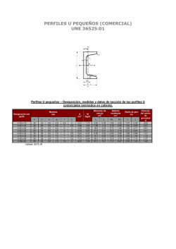
PERFILES ABIERTOS CONFORMADOS EN FRÍO
PERFIL CF. UNE 36-573-79
PERFIL C CUADRADO CONFORMADO EN FRÍO
Perfiles abiertos normalizados – Perfil C cuadrado - Medidas
PERFIL
CF 20 x 1.5
CF 25 x 1.5
CF 25 x 2.0
CF 30 x 1.5
CF 30 x 2.0
CF 40 x 1.5
CF 40 x 2.0
CF 50 x 2.0
CF 50 x 3.0
CF 65 x 4.0
b
mm
20
25
25
30
30
40
40
50
50
65
Dimensiones
c
e
mm
mm
8
1.5
10
1.5
10
2.0
10
1.5
10
2.0
15
1.5
15
2.0
20
2.0
20
3.0
25
4.0
r
mm
1.6
1.6
2.5
1.6
2.5
1.6
2.5
2.5
3.0
6.0
A
cm2
M
kg/m
u
m2/m
d
cm
xM
cm
0.988
1.27
1.62
1.50
1.92
2.10
2.72
3.52
5.10
8.60
0.776
0.999
1.27
1.18
1.50
1.65
2.13
2.76
4.00
6.75
0.135
0.173
0.166
0.203
0.196
0.283
0.276
0.356
0.347
0.439
0.944
1.18
1.18
1.36
1.35
1.86
1.86
2.36
2.36
3.04
1.91
2.57
2.23
2.98
2.68
4.42
4.11
5.56
5.19
6.13
Perfiles abiertos normalizados – Perfil C cuadrado - Momentos
PERFIL
CF 20 x 1.5
CF 25 x 1.5
CF 25 x 2.0
CF 30 x 1.5
CF 30 x 2.0
CF 40 x 1.5
CF 40 x 2.0
CF 50 x 2.0
CF 50 x 3.0
CF 65 x 4.0
Referido al eje X - X
IX
WX
iX
cm4
cm3
cm
0.578
0.578
0.765
1.21
0.967
0.974
1.45
1.16
0.947
2.17
1.45
1.20
2.66
1.77
1.18
5.46
2.73
1.61
6.84
3.42
1.59
14.0
5.60
2.00
19.4
7.76
1.95
54.9
16.9
2.53
Referido al eje Y - Y
IY
WY
iY
cm4
cm3
cm3
0.524
0.496
0.728
1.10
0.834
0.930
1.31
0.993
0.901
1.85
1.13
1.11
2.24
1.36
1.08
4.88
2.28
1.52
6.08
2.84
1.50
12.8
4.86
1.91
17.7
6.70
1.86
49.0
14.2
2.39
Siendo:
A
M
I
W
i
d
xM
IT
IA
u
=
=
=
=
=
=
=
=
=
=
Area de la sección recta.
Masa por metro.
Momento de inercia (referido al eje correspondiente de flexión).
Momento resistente (referido al eje correspondiente de flexión).
√(I/A) = Radio de giro (referido al eje correspondiente de flexión).
Distancia del centro de gravedad a la cara exterior.
Distancia del centro de presión M al eje Y-Y.
Módulo de torsión.
Módulo de alabeo.
Perímetro (superficie por metro lineal).
IT
cm4
IA
cm6
0.00742
0.00956
0.0216
0.0112
0.0256
0.0158
0.0363
0.0469
0.153
0.459
1.12
3.44
4.76
6.63
9.16
32.8
45.2
151
217
1120
PERFIL C RECTANGULAR CONFORMADO EN FRÍO
Perfiles abiertos normalizados – Perfil C rectangular - Medidas
PERFIL
h
mm
CF 60 x 2.0
CF 60 x 2.5
CF 60 x 3.0
CF 80 x 2.0
CF 80 x 2.5
CF 80 x 3.0
CF 100 x 2.0
CF 100 x 2.5
CF 100 x 3.0
CF 120 x 2.0
CF 120 x 2.5
CF 120 x 3.0
CF 140 x 2.0
CF 140 x 2.5
CF 140 x 3.0
CF 160 x 2.0
CF 160 x 2.5
CF 160 x 3.0
CF 180 x 2.0
CF 180 x 2.5
CF 180 x 3.0
CF 200 x 2.0
CF 200 x 2.5
CF 200 x 3.0
CF 225 x 2.5
CF 225 x 3.0
CF 225 x 4.0
CF 250 x 2.5
CF 250 x 3.0
CF 250 x 4.0
CF 275 x 2.5
CF 275 x 3.0
CF 275 x 4.0
CF 300 x 2.5
CF 300 x 3.0
CF 300 x 4.0
60
60
60
80
80
80
100
100
100
120
120
120
140
140
140
160
160
160
180
180
180
200
200
200
225
225
225
250
250
250
275
275
275
300
300
300
Dimensiones
b
c
e
m
mm
mm
m
40
15
2.0
40
15
2.5
40
15
3.0
40
15
2.0
40
15
2.5
40
15
3.0
40
15
2.0
40
15
2.5
40
15
3.0
50
20
2.0
50
20
2.5
50
20
3.0
50
20
2.0
50
20
2.5
50
20
3.0
60
20
2.0
60
20
2.5
60
20
3.0
60
20
2.0
60
20
2.5
60
20
3.0
60
20
2.0
60
20
2.5
60
20
3.0
80
25
2.5
80
25
3.0
80
25
4.0
80
25
2.5
80
25
3.0
80
25
4.0
80
25
2.5
80
25
3.0
80
25
4.0
80
25
2.5
80
25
3.0
80
25
4.0
r
mm
2.5
2.5
3.0
2.5
2.5
3.0
2.5
2.5
3.0
2.5
2.5
3.0
2.5
2.5
3.0
2.5
2.5
3.0
2.5
2.5
3.0
2.5
2.5
3.0
2.5
3.0
6.0
2.5
3.0
6.0
2.5
3.0
6.0
2.5
3.0
6.0
A
cm2
M
kg/m
u
m2/m
d
cm
xM
cm
3.12
3.84
4.50
3.52
4.34
5.10
3.92
4.84
5.70
4.92
6.08
7.20
5.32
6.58
7.80
6.12
7.58
9.00
6.52
8.08
9.60
6.92
8.58
10.2
10.5
12.5
16.2
11.1
13.2
17.2
11.7
14.0
18.2
12.3
14.7
19.2
2.45
3.01
3.53
2.76
3.40
4.00
3.08
3.80
4.48
3.86
4.78
5.65
4.17
5.17
6.12
4.80
5.95
7.07
5.12
6.35
7.54
5.43
6.74
8.01
8.21
9.78
12.7
8.70
10.4
13.5
9.19
11.0
14.3
9.68
11.5
15.1
0.316
0.312
0.307
0.356
0.352
0.347
0.396
0.392
0.387
0.496
0.492
0.487
0.536
0.532
0.527
0.616
0.612
0.607
0.656
0.652
0.647
0.696
0.692
0.687
0.842
0.837
0.819
0.892
0.887
0.869
0.942
0.937
0.919
0.992
0.987
0.969
1.63
1.63
1.63
1.46
1.46
1.46
1.32
1.32
1.32
1.72
1.72
1.72
1.60
1.60
1.60
1.86
1.86
1.86
1.75
1.76
1.75
1.66
1.66
1.66
2.38
2.38
2.36
2.25
2.25
2.23
2.14
2.14
2.12
2.04
2.04
2.02
3.72
3.62
3.45
3.40
3.31
3.17
3.14
3.06
2.94
4.22
4.14
4.02
3.97
3.89
3.78
4.62
4.54
4.43
4.40
4.33
4.22
4.20
4.13
4.04
5.96
5.86
5.53
5.70
5.60
5.30
5.47
5.37
5.09
5.25
5.16
4.89
PERFIL C RECTANGULAR CONFORMADO EN FRÍO
Perfiles abiertos normalizados – Perfil C rectangular - Momentos
PERFIL
CF 60 x 2.0
CF 60 x 2.5
CF 60 x 3.0
CF 80 x 2.0
CF 80 x 2.5
CF 80 x 3.0
CF 100 x 2.0
CF 100 x 2.5
CF 100 x 3.0
CF 120 x 2.0
CF 120 x 2.5
CF 120 x 3.0
CF 140 x 2.0
CF 140 x 2.5
CF 140 x 3.0
CF 160 x 2.0
CF 160 x 2.5
CF 160 x 3.0
CF 180 x 2.0
CF 180 x 2.5
CF 180 x 3.0
CF 200 x 2.0
CF 200 x 2.5
CF 200 x 3.0
CF 225 x 2.5
CF 225 x 3.0
CF 225 x 4.0
CF 250 x 2.5
CF 250 x 3.0
CF 250 x 4.0
CF 275 x 2.5
CF 275 x 3.0
CF 275 x 4.0
CF 300 x 2.5
CF 300 x 3.0
CF 300 x 4.0
Referido al eje X – X
IX
WX
iX
cm4
cm3
cm
17.8
5.93
2.39
21.5
7.16
2.37
24.6
8.22
2.34
34.9
8.74
3.15
42.4
10.6
3.13
49.0
12.3
3.10
59.2
11.8
3.89
72.1
14.4
3.86
83.6
16.7
3.83
109
18.1
4.70
133
22.2
4.68
156
25.9
4.65
156
22.3
5.42
192
27.4
5.40
225
32.1
5.37
240
30.0
6.26
295
36.8
6.23
346
43.3
6.20
316
35.1
6.97
389
43.2
6.94
458
50.9
6.90
406
40.6
7.66
500
50.0
7.63
588
58.8
7.60
806
71.7
8.78
953
84.7
8.75
1210
108
8.66
1030
82.6
9.65
1220
97.7
9.62
1560
125
9.52
1290
94.1
10.5
1530
111
10.5
1960
142
10.4
1590
106
11.4
1890
126
11.3
2410
161
11.2
IY
cm4
7.16
8.56
9.71
8.00
9.57
10.9
8.67
10.4
11.8
17.9
21.7
25.0
18.9
22.9
26.3
30.5
37.0
42.9
31.7
38.5
44.5
32.7
39.7
46.0
90.8
106
131
93.8
110
136
96.5
113
140
98.9
116
143
Referido al eje Y - Y
WY
iY
cm3
cm3
3.03
1.52
3.62
1.49
4.10
1.47
3.15
1.51
3.77
1.49
4.28
1.46
3.24
1.49
3.87
1.46
4.40
1.44
5.47
1.91
6.61
1.89
7.60
1.86
5.56
1.89
6.72
1.86
7.74
1.84
7.37
2.23
8.95
2.21
10.4
2.18
7.46
2.20
9.06
2.18
10.5
2.15
7.53
2.17
9.15
2.15
10.6
2.12
16.2
2.95
18.9
2.92
23.3
2.85
16.3
2.91
19.1
2.88
23.5
2.81
16.5
2.87
19.2
2.84
23.8
2.77
16.6
2.83
19.4
2.80
24.0
2.73
Siendo:
A
M
I
W
i
d
xM
IT
IA
u
=
=
=
=
=
=
=
=
=
=
Area de la sección recta.
Masa por metro.
Momento de inercia (referido al eje correspondiente de flexión).
Momento resistente (referido al eje correspondiente de flexión).
√(I/A) = Radio de giro (referido al eje correspondiente de flexión).
Distancia del centro de gravedad a la cara exterior.
Distancia del centro de presión M al eje Y-Y.
Módulo de torsión.
Módulo de alabeo.
Perímetro (superficie por metro lineal).
IT
cm4
IA
cm6
0.0416
0.0800
0.135
0.0469
0.0904
0.153
0.0523
0.101
0.171
0.0656
0.127
0.216
0.0709
0.137
0.234
0.0816
0.158
0.270
0.0869
0.169
0.288
0.0923
0.179
0.306
0.218
0.374
0.865
0.231
0.396
0.916
0.244
0.419
0.971
0.257
0.441
1.02
74.9
90.4
109
122
148
179
189
228
275
547
668
808
751
917
1100
1490
1830
2190
1930
2360
2830
2440
2980
3560
8320
9980
14100
10500
12600
17600
13100
15600
21700
15900
19000
26200
© Copyright 2026

