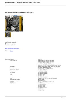
CX H81-M1 Series
Conectores internos
Dual-channel, 2 Slots, Non-ECC, Unbuffered, 240 pin DDR3, Max. up to 16GB for all.
PS/2 KB/MS ports
Types: 1066/PC3-8500, 1333/PC3-10600, 1600/PC3-12800
Graphics
12
ROM Recovery
Realtek ALC662
Gigabit : Realtek RTL8111G
BUZZER
Memory
sockets
Serial Port/
Display (DVI) port
2 x PCI slots
LAN
COM
2x SATA III connectors
Storage
10
Display (VGA)/
HDMI ports
2x SATA II Connectors
8 x USB 2.0 ports, 12/480Mbps
USB
ATX power
connector
7
2 x USB 3.0 ports, 5Gbps
1x PS/2 Mouse/Keyboard
LAN (RJ-45) port
& USB3.0 ports
4x USB2.0 ports
USB2.0
connector
System FAN 14
1x ATX power connector
10
1x Front panel audio connector
1x Front panel connector
8
1x Internal serial port connectors
1x TPM (Trusted Platform Module) connector
SATA3.0/2.0
connectors
PCI slots
1x Chassis intrusion connector
7
Front panel
connector
1x ME Update
BIOS
SPI 64Mb (AMI)
Form factor
uATX, 9.6inches x 7.5 inches
1
2
SPDIF_OUT
Front panel
audio connector
Conectores del panel trasero
Display (VGA) port
A
LAN (RJ-45) port
B
6
CLEAR CMOS
3 2 1
3 2 1
Normal
(Default)
Clear
CMOS
Ground
+5 Volts
+5 Volts
+5 Volts
-5 Volts
Ground
Ground
Ground
PSON#
Ground
-12 Volts
+3 Volts
A
INTRUDER Clear CMOS
FLASH OVERRIDE
(Intel Management Engine) SELECTOR
FLASH_OVERRIDE
1
1
2
2
Enable
(Default)
USB3.0
Disable
13
ATX CPU POWER
CONNECTOR
ATX_CPU
ROM RECOVERY
CONNECTOR
SPI_CS#
SPI_MOSI
SPI_MISO
SPI_CS
+3P3VSB
GND
SPI_CLK
ATXPOWER
Ground
+12V_CPU
USB2.0
5
11
Ground
+12V_CPU
Pink: Mic Input
HDMI ports
4
Serial port TPM header
FLASH
header
OVERRIDE
B
Clear CMOS
Lime: Front L/R Output
Display (DVI-D)
port
3
LPT header
Selectores de función
Blue: Line Input
Keyboard
(PS/2) Port
F_USB3
F_USB2
SATA1
UEFI
14
12
CPU FAN
CONNECTOR
Ground
CPU FAN PWR
CPU FAN TACH
CPU FAN PWM
1x Clear CMOS selector & 1x Clear password selector
SERIAL Port
+SBV
USB*(-)
USB*(+)
Ground
NC
SATA2
ATX POWER
CONNECTOR
+3 Volts
+12 Volts
+12 Volts
+5V Standby
ATX_PWRGD
Ground
+5 Volts
Ground
+5 Volts
Ground
+3 Volts
+3 Volts
2 x USB 2.0 connectors
Mouse (PS/2) Port
+SBV
USB*(-)
USB*(+)
Ground
PCI Express slot (x1)
4x SATA connectors
Internal Selectors
USB CONNECTORS
SATA3
FRONT PANEL
1x System fan connector
Internal
connectors
9
SATA3.0/2.0
CONNECTORS
PWRBTN PLED
PCI Express slot (x16)
1x CPU fan connector
INTRUDER
SATA4
PLED(+)
PLED( - )
9
Audio jacks
1x ATX CPU power connector
PWR
Ground
1x LAN (RJ-45) port + 2x USB2.0 ports
3x Audio jacks (5.1 CH)
8
FRONT PANEL
CONNECTOR
HDLED(+)
HDLED( - )
Ground
Reset
NC
1x Display (DVI) port
1x HDMI port
TPM
RESET HDLED
USB 2.0 ports
1x Display (VGA) port
Rear Panel I/O
ports
(Depending on
Model)
INTRUDER
GND
1 x PCI Express slot (x1)
NC
LAD2
LAD1
GND
NC
SERIRQ
GND
SMB_CLK_MAIN
1 x PCI Express slot (x16)
Audio
6
11
Integrated Graphics
Expansion slots
TPM (Trusted Platform
Module) CONNECTOR
Ground
SATA_RX(+)
SATA_RX(-)
Ground
SATA_TX(-)
SATA_TX(+)
Ground
Memory
CPU fan connector
13
Intel H81
DDCD*#
TTXD*
Ground
RRTS*#
RRI*#
Chipset
5
RRXD*
DDTR*#
DDSR*#
CCTS*#
TDP: 95W
INTERNAL SERIAL
PORT CONNECTOR
CK_33M_TPM
LFRAME#
PLTRST#
LAD3
+3P3V
LAD0
LDREQ0#
+3P3VSB
GND
LPCPD#
ATX CPU power
connector
Intel socket 1150
CPU Socket
4
PARAELLE
Ground
INTRUDER#
Diseño de Motherboard
INTERNAL PARAELLE
PORT CONNECTOR
NC
Ground
Ground
Ground
Ground
Ground
Ground
Ground
Ground
SLIN#
PINIT#
ERROR#
AFD#
SPDIF_OUT
F_AUDIO
Especificaciones
3
SPDIF_OUT
CONNECTOR
MIC*_L
MIC*_R
LINE*_R
GND
LINE*_L
• Especificaciones
• Selectores de función
• Diseño de Motherboard
• Conectores internos
• Conectores del panel trasero
2
SLCT
PE
BUSY
ACK#
SPD7
SPD6
SPD5
SPD4
SPD3
SPD2
SPD2
SPD1
SPD0
STB#
GND
F_AUDIO_DET#
MIC*_RTU
Contenidos
FRONT PANEL
AUDIO CONNECTOR
+5V
1
Ground
SPDIF Out
Referencia de diseño de Motherboard
LINE*_RTU
CX
H81-M1 Series
CPU_FAN
SYSTEM FAN
CONNECTOR
Ground
SYS FAN PWR
SYS FAN TACH
SYS FAN PWM
SYS_FAN
Indicadores LED del puerto LAN
Left (ACTIVITY)
Green: Activity
Off:
No activity
LAN port
Right (LINK)
Orange: 1G Link
Green:
100M Link
Off:
10M Link
Para borrar los ajustes de usuario CMOS RTC RAM:
1. Apague el ordenador y desconecte el cable de alimentación.
2. Mueva el jumper para borrar el BIOS por 5 a 10 segundos,
luego mueva jumper por defecto.
3. Conecte el cable de alimentación y encienda el equipo.
4. Durante el proceso de arranque, entrar en la configuración del BIOS
para volver a entrar en la configuración del usuario.
Soporte técnico: 0810 - 7777 - 247
www.redcx.com
[email protected]
Las imágenes son sólo ilustrativas.
© Copyright 2026

