
66CLP BALANCED BREAKAWAY
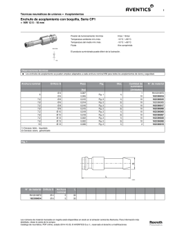
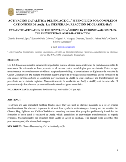
206203 August 2015
66CLP BALANCED BREAKAWAY
ACOPLAMIENTOS DE SEGURIDAD EQUILIBRADOS TIPO “BREAKAWAY” 66CLP
IMPORTANT SAFEGUARDS
MEDIDAS PREVENTIVAS
IMPORTANTES
•For your protection, please read these safety
instructions completely before installing and
operating this equipment.
• Para su protección, lea completamente estas
instrucciones de seguridad antes de instalar y
operar este equipo.
•Keep this manual on file for future reference.
• Mantenga archivado este manual para futuras
consultas.
•This manual contains material that may be
required by authorities having jurisdiction
to be on site at all times.
• Las autoridades con jurisdicción pueden exigir
que el material de este manual esté in situ en
todo momento.
•Carefully observe all warnings, precautions
and instructions for this equipment and
in the operating instructions and adhere
to them.
• Observe y cumpla cuidadosamente todas las
advertencias, precauciones e instrucciones
de este equipo, y siga las instrucciones para
el funcionamiento del equipo.
THIS MANUAL MUST BE LEFT WITH FACILITY MANAGEMENT
ESTE MANUAL DEBE ESTAR EN POSESIÓN DEL ENCARGADO DE LA INSTALACIÓN
WARNINGS & INSTRUCTIONS/ADVERTENCIAS E INSTRUCCIONES............................................. Page/Página 2
INSTALLATION/INSTALACIÓN............................................................................................................ Pages/Páginas 2
DRIVE OFF PROCEDURE/PROCEDIMIENTO DE PUESTA EN MARCHA..................................Pages/Páginas 3-5
MAINTENANCE/MANTENIMIENTO....................................................................................................... Page/Página 6
SITE NAME:
NOMBRE DEL SITIO:
ADDRESS:
DIRECCIÓN:
SERIAL NUMBER OR BREAKAWAY:
NÚMERO DE SERIE DE O BREAKAWAY:
DATE OF INSTALLATION:
FECHA DE INSTALACIÓN:
CONTRACTOR IN CHARGE
OF THE FACILITY:
CONTRATISTA A CARGO DE
LA INSTALACIÓN:
Please visit OPW’s website: www.opwglobal.com for further information or contact OPW Customer Service at 1-800-422-2525 (US)
Visite el sitio web de OPW: www.opwglobal.com para más información o comuníquese con el Servicio al Cliente de OPW al 1-800-422-2525 (EE. UU.)
9-16
ARB Approved IOM 9 -EVR Balance Breakaways VR-203-O and VR-204-O
IOM 9-EVR aprobado por ARB para acoplamientos de seguridad tipo “breakaway” equilibrados modelos VR-283-O y VR-204-O
11
INSTALLATION/INSTALACIÓN
206203 August 2015
ADVERTENCIA
Failure to comply with the following warnings could result in
property damage, injury or death.
El incumplimiento de las siguientes advertencias puede provocar daños
a la propiedad, lesiones e incluso la muerte.
Fire Hazard
Do not use power tools (Class I Division I and Class I Division II)
during installation process and maintenance of equipment.
Chemical Exposure Hazard
Always wear appropriate safety equipment during installation
or maintenance of equipment.
Fire Hazard
Do not install an unlisted ad/billboard or other unlisted after-market
device on any automatic nozzle. Doing so may change the sensitivity
of the shut-off mechanism. Nozzle may not shut off, causing a
fuel spill. Reference: sensitivity test per Underwriters
Laboratories specification UL842.
Peligro de incendio
No utilice herramientas eléctricas (Clase I División I y Clase I División II)
durante el proceso de instalación y mantenimiento del equipo.
Peligro de exposición a sustancias químicas
Use siempre equipo de seguridad adecuado durante la instalación
o el mantenimiento del equipo.
Peligro de incendio
No instale anuncios, carteleras ni dispositivos accesorios no autorizados
en ninguna pistola surtidora automática. Si lo hace puede cambiar la
sensibilidad del mecanismo de cierre. La pistola podría no cerrarse y
provocar un derrame de combustible. Consultar: prueba de sensibilidad
según la especificación UL842 de Underwriters Laboratories.
WARNINGS
ADVERTENCIAS
• Dispensing system must be tested to determine if a maximum
separation force of 350 pounds would damage it.
• Dispenser must be securely attached to the dispensing island.
• Keep gasoline away from your eyes and skin.
• Keep gasoline out of reach of children.
PREPARATION AND TEST
• Attach a spring scale to the location where
the breakaway will be installed (see FIG 1).
1-7/8" - 12
ADAPTOR/
ADAPTADOR DE
1-7/8" – 12
FORCE/
FUERZA
• Apply a 350 pound pull-force at various
angles to the dispenser.
• Check emergency valves, dispenser, and hose
assemblies for damage.
• If there is no damage, the installation is ready
for breakaways.
INSTALLATION – HIGH HOSE MPD
ROPE/
SOGA
Figure 1/Figura 1
• Orient breakaway based on flow arrow on
outside cover.
• Install breakaway into whip hose from the
dispenser first (see FIG 2).
Hose Whip/
Manguera
flexible
Main
Hose/
Manguera
principal
• Use flats at top of breakaway to tighten.
• Tighten breakaway connection to 50 footpounds torque.
• Install long hose into bottom of breakaway.
• Use flats at bottom of breakaway to
tighten.
• Tighten breakaway connection to 50 footpounds torque.
Figure 2/Figura 2
• Do not wrench across the body of the breakaway.
• Do not over-tighten.
• If a separation occurs, see reconnection section on page 3.
• El sistema de provisión debe comprobarse para determinar si una
máxima fuerza de separación de 350 libras le ocasionaría daños.
• El surtidor deberá estar conectado firmemente a la plataforma
de provisión.
• Mantenga la gasolina lejos de los ojos y la piel.
• Mantenga la gasolina fuera del alcance de los niños.
PREPARACIÓN Y PRUEBA
• Conecte una báscula a resorte en el lugar en donde se
instalará el acoplamiento de seguridad tipo “breakaway”
(consulte la FIG. 1).
• Aplique una fuerza de tracción de 350 libras a diversos
ángulos al surtidor.
• Revise las válvulas de emergencia, el surtidor y los
conjuntos de mangueras en busca de daños.
• Si no hay daños, la instalación está lista para la colocación
de los acoplamientos de seguridad.
INSTALACIÓN – ALTO MPD DE LA MANGUERA
• Oriente el acoplamiento de seguridad tipo “breakaway” según
la flecha de flujo sobre la cubierta externa.
• Instale el acoplamiento de seguridad tipo “breakaway” en la
manguera flexible primero desde el surtidor (consulte la FIG. 2).
• Utilice las piezas planas en la parte superior del acoplamiento
de seguridad tipo “breakaway” para apretarlo.
• Apriete la conexión del acoplamiento de seguridad tipo
“breakaway” hasta una torsión de 50 pies-libras.
• Instale la manguera larga en la parte inferior del acoplamiento
de seguridad tipo “breakaway”.
• Utilice las piezas planas en la parte inferior del acoplamiento
de seguridad tipo “breakaway” para apretarlo.
• Apriete la conexión del acoplamiento de seguridad tipo
“breakaway” hasta una torsión de 50 pies-libras.
• No apriete con llave el cuerpo del acoplamiento de seguridad
tipo “breakaway”.
• No apriete demasiado.
• Si se produce una separación, consulte la sección de
reconexión en la página 3.
9-17
2
ARB Approved IOM 9 -EVR Balance Breakaways VR-203-O and VR-204-O
IOM 9-EVR aprobado por ARB para acoplamientos de seguridad tipo “breakaway” equilibrados modelos VR-283-O y VR-204-O
DRIVE OFF PROCEDURE/ PROCEDIMIENTO DE PUESTA EN MARCHA
The following maintenance may be
performed by the GDF owner/operator or
any authorized service contractor
206203 August 2015
El siguiente mantenimiento puede ser realizado
por el propietario/operador del GDF o por cualquier
contratista de servicio autorizado
ADVERTENCIA
It will require at least 40-50 lbs. of effort to re-connect the breakaway.
An optional clamping tool is available (purchased separately) to make
the re-connection process easier. If you have any questions or concerns,
STOP and contact an authorized service contractor.
Se requerirán al menos 40-50 lbs. de esfuerzo para reconectar el acoplamiento
de seguridad tipo “breakaway”. Se dispone de una herramienta opcional de
apriete (se compra por separado) para facilitar el proceso de reconexión.
Si tiene preguntas o inquietudes, DETÉNGASE y póngase en contacto con un
contratista de servicio autorizado.
Some residual pressure may be present on the dispenser side of the
separated breakaway – use caution when removing. A small amount of
gasoline may leak out of the connection – a towel wrapped loosely
around the breakaway can help minimize fuel spills.
Puede haber alguna presión residual del lado del surtidor del acoplamiento de
seguridad tipo “breakaway” separado – tenga cuidado al desmontarlo. Puede
haber fugas de una pequeña cantidad de gasolina en la conexión – una toalla
envuelta de manera floja alrededor del acoplamiento de seguridad tipo
“breakaway” puede ayudar a minimizar los derrames de combustible.
ADVERTENCIA
BREAKAWAY RECONNECTION PROCEDURE
PROCEDIMIENTO DE RECONEXIÓN DEL ACOPLAMIENTO DE
SEGURIDAD TIPO “BREAKAWAY”
1. Verify the dispenser is not authorized/activated.
1. Verifique que el surtidor no esté autorizado/activado.
2. Remove both halves of the breakaway from the hose.
2. Desmonte ambas mitades del acoplamiento de seguridad tipo
“breakaway” de la manguera.
3. Perform visual inspection of the breakaway body components.
a. If the “Spud” assembly (see FIG 3, page 4) is damaged beyond
repair, the entire breakaway will need to be replaced.
3. Realice una inspección visual de los componentes del cuerpo del
acoplamiento de seguridad tipo “breakaway”.
b. If the “Body” assembly (see FIG 3, page 4) is damaged beyond
repair, the entire breakaway must be replaced.
a. Si el ensamble con el “relieve” (consulte la FIG. 3, página 4) está
dañado sin posibilidad de reparación, deberá reemplazarse todo
el acoplamiento de seguridad tipo “breakaway”.
c. Ensure the “spring” is not damaged or missing (see FIG 3, page 4).
b. Si el ensamble con el “cuerpo” (consulte la FIG. 3, página 4) está
dañado sin posibilidad de reparación, deberá reemplazarse todo
el acoplamiento de seguridad tipo “breakaway”.
4. Replace damaged and missing breakaway components.
a. The O-ring will need to be replaced every time breakaway
separation occurs, replace with part number 204870.
c. Asegúrese de que el “muelle” no esté dañado o falte (consulte la
FIG. 3, página 4).
b. If the Spring is damaged (or missing), replace with part
number 204872.
c. If the Plastic Sleeve is damaged, replace with part number 204811.
4. Reemplace los componentes dañados o faltantes del acoplamiento de
seguridad tipo “breakaway”.
a. El aro tórico deberá reemplazarse cada vez que ocurra una
separación del acoplamiento de seguridad tipo “breakaway”,
reemplace con el número de pieza 204870.
b. Si el muelle está dañado (o falta), reemplace con el número de
pieza 204872.
c. Si el manguito plástico está dañado, reemplace con el número
de pieza 204811.
9-18
ARB Approved IOM 9 -EVR Balance Breakaways VR-203-O and VR-204-O
IOM 9-EVR aprobado por ARB para acoplamientos de seguridad tipo “breakaway” equilibrados modelos VR-283-O y VR-204-O
3
DRIVE OFF PROCEDURE/ PROCEDIMIENTO DE PUESTA EN MARCHA
5. Re-connection procedure:
206203 August 2015
5. Procedimiento de reconexión::
a. Lubricate the O-ring with petroleum jelly or silicone grease.
a. Lubrique el aro tórico con vaselina o grasa silicónica.
b. Push the “spud” into the “body” by applying increasing force while
wiggling the “spud” in a rotating motion until it enters the spring
in the “body”.
b. Empuje el “relieve” en el “cuerpo” aplicando una fuerza
creciente mientras desplaza suavemente el “relieve” con un
movimiento rotativo hasta que ingrese el muelle en el
interior del “cuerpo”.
c. Align the pins with slots and continue pushing the “spud” into the
“body” until they latch together. The pins should be in the bottom
of the slot. See “connected” picture in FIG 3.
c. Alinee los pasadores con las ranuras y continúe empujando el
“relieve” al interior del “cuerpo” hasta que se enganchen entre
sí. Los pasadores deben llegar al fondo de la ranura. Consulte
la ilustración del dispositivo “conectado” en la FIG. 3.
d. Use a ratchet style one-handed bar clamp such as Bessey part
number DUO30-8 (Grainger part number 6XE60) or equivalent
to compress the two halves together (see FIG 4).
d. Utilice una abrazadera de barra de tipo trinquete, de uso con
una mano, tal como el número de pieza de Bessey DUO30-8
(número de pieza de Grainger 6XE60) o equivalente para
comprimir las dos mitades entre sí (consulte la FIG. 4).
6. Reinstall the breakaway onto the hose ends, making sure that the
arrow on the label is pointing toward the nozzle.
7. Authorize the dispenser and perform functional testing, refer to VST IOM 5.
6. Vuelva a colocar el acoplamiento de seguridad tipo “breakaway”
en los extremos de la manguera, asegurándose de que la flecha
en la etiqueta esté orientada hacia la boquilla.
7. Autorice el surtidor y realice las pruebas funcionales;
consulte VST IOM 5.
BODY/ CUERPO
SHOWN CUT AWAY FOR CLARITY /
SE MUESTRA ESQUEMA DE CORTE
PARA MAYOR CLARIDAD
PIN AT BOTTOM OF SLOT/ PASADOR
EN EL FONDO DE LA RANURA
TO DISPENSER/
AL SURTIDOR
PIN/
PASADOR
SLOT/
RANURA
O-RING/ ARO TÓRICO
SPRING/ MUELLE
SPUD/
RELIEVE
TO NOZZLE/
A LA
BOQUILLA
IMPORTANT: PAINTED STRIPE
ON SPRING MUST BE FACING
THIS DIRECTION FOR PROPER
OPERATION. /
PLASTIC SLEEVE/
MANGUITO
PLÁSTICO
BREAKAWAY SHOWN SEPARATED/
SE MUESTRA EL ACOPLAMIENTO DE
SEGURIDAD TIPO “BREAKAWAY” SEPARADO
IMPORTANTE: PINTAR STRIPE
EN PRIMAVERA LA FRANJA DEBE
ESTAR ORIENTADA DE ESTE
MODO PARA UN FUNCIONAMIENTO CORRECTO
BREAKAWAY SHOWN CONNECTED/
SE MUESTRA EL ACOPLAMIENTO DE SEGURIDAD
TIPO “BREAKAWAY” CONECTADO
Figure 3/Figura 3
Please visit OPW’s website: www.opwglobal.com for further information or contact OPW Customer Service at 1-800-422-2525 (US)
Visite el sitio web de OPW: www.opwglobal.com para más información o comuníquese con el Servicio al Cliente de OPW al 1-800-422-2525 (EE. UU.)
9-19
4
ARB Approved IOM 9 -EVR Balance Breakaways VR-203-O and VR-204-O
IOM 9-EVR aprobado por ARB para acoplamientos de seguridad tipo “breakaway” equilibrados modelos VR-283-O y VR-204-O
206203 August 2015
DRIVE OFF PROCEDURE/ PROCEDIMIENTO DE PUESTA EN MARCHA
Step 1:
Place separated breakaway
in clamp jaws with the pins
aligned with the slots
Step 3:
Breakaway is now fully connected
when the pins are at the bottom
of the slots. Press the release
button on the clamp to release
the breakaway from the clamp.
Paso 1:
Coloque el acoplamiento
de seguridad separado en
mordazas de sujeción con los
pasadores alineados con las
ranuras
Paso 3:
El acoplamiento de seguridad
tipo “breakaway” está
ahora totalmente conectado
cuando los pasadores están
en el fondo de las ranuras.
Pulse el botón de liberación
de la abrazadera para liberar
el acoplamiento de seguridad
tipo “breakaway” de la
abrazadera.
Clamping/spreading switch:
Make sure it is set in the
“clamp” direction
Interruptor de sujeción/
difusión: Asegúrese de que
esté colocado en la dirección
de “fijación”
Step 2:
Squeeze lever several
times to ratchet the clamp
closed to re-connect
breakaway
Paso 2:
Presione varias veces la
palanca de trinquete para
cerrar la abrazadera y
volver a conectar el
acoplamiento de
seguridad tipo
“breakaway”
Clamp release button
Botón de liberación
de la abrazadera
Figure 4/Figura 4
The following is to be completed by the individual reconnecting the breakaway:
I, ____________________________, hereby declare that I have followed these instructions per the manufacturer’s recommendations on this
day ________, in the month of _________________, 2012
Lo siguiente deberá ser completado por el individuo que reconecta el acoplamiento de seguridad tipo “breakaway”:
Yo, ____________________________, por este medio declaro que he seguido estas instrucciones de acuerdo con las recomendaciones del
fabricante el día ________ del mes de _________________ de 2012
Please visit OPW’s website: www.opwglobal.com for further information or contact OPW Customer Service at 1-800-422-2525 (US)
Visite el sitio web de OPW: www.opwglobal.com para más información o comuníquese con el Servicio al Cliente de OPW al 1-800-422-2525 (EE. UU.)
9-20
ARB Approved IOM 9 -EVR Balance Breakaways VR-203-O and VR-204-O
IOM 9-EVR aprobado por ARB para acoplamientos de seguridad tipo “breakaway” equilibrados modelos VR-283-O y VR-204-O
5
6
Date and time of each repair. / Fecha y hora de cada reparación.
Description of services performed. / Descripción de los servicios realizados.
(vi)Receipts for parts used in the repair and, if applicable, work orders, which shall
include the name and signature of the person responsible for performing the repairs. /
Recibos de los repuestos utilizados y, si corresponde, órdenes de trabajo con nombre
y firma de la persona responsable de la reparación.
(v)Each component that was installed as replacement, if applicable, including the
required component identification information. Example: manufacturer and
product serial number. / Repuestos instalados (si corresponde), incluidos los datos de
identificación de cada uno de ellos. Ejemplo: fabricante y número de serie del producto.
9-21
4/1/00
Date of
Problem
(MM/DD/YY) /
Fecha del
problema
(MM/DD/AA)
3:30 pm
Grade of Gas: 87 / Octanaje: 87
ARB Approved IOM 9 -EVR Balance Breakaways VR-203-O and VR-204-O
IOM 9-EVR aprobado por ARB para acoplamientos de seguridad tipo “breakaway” equilibrados modelos VR-283-O y VR-204-O
Please visit OPW’s website: www.opwglobal.com for further information or contact OPW Customer Service at 1-800-422-2525 (US)
Visite el sitio web de OPW: www.opwglobal.com para más información o comuníquese con el Servicio al Cliente de OPW al 1-800-422-2525 (EE. UU.)
Grade of Gas: / Octanaje:
Noozzle #: / Pistola nº:
Grade of Gas: / Octanaje:
Nozzle #: / Pistola nº:
Nozzle spout for 3-87 out of round, Called repair company on 4/1. / Pérdida de circularidad
en la boquilla de la pistola 3-87, Llamada a la
empresa de mantenimiento el 1/4.
4/2/00
Nozzle #: 3 / Pistola nº: 3
Description of Defect,
Alarm or Spill /
Descripción del defecto, la alarma o
el derrame
Date/Time
of Repair/
Remedy
(MM/DD/YY) /
Fecha y hora de la
reparación/
intervención
(MM/DD/AA)
Replaced OPW 11VAI-69 nozzle serial #456789 with new OPW 11VAI-69
nozzle serial #458901. / Cambio de pistola OPW 11VAI-69 (nº serie 456789
por nueva pistola OPW 11VAI-69 (nº serie 458901).
Description of Repair or Remedy
List each component repaired, replaced and/or installed
including make, model and serial number of old and new components /
Descripción de la reparación o intervención. Anote cada
componente reparado, sustituido y/o instalado e incluya la marca, el
modelo y el número de serie de los componentes antiguos y nuevos
560-345-6789
La Habra, CA
1111 E. Fourth Ave.
Tom Smith, ABC Nozzle Co.
Name/Company/Address
Phone Number of Person
Who Performed the Repair /
Nombre/Empresa/Dirección /
Número de teléfono de la persona
encargada de la reparación
ALL repairs should be logged! / Se deben anotar TODAS las reparaciones
Whether the new equipment is from the station’s own stock or from a maintenance company, everything should be entered into the daily repair log. / Haga todas las anotaciones necesarias en el registro
diario de reparaciones, tanto si los repuestos proceden del almacén de la estación como de una empresa de mantenimiento.
(iv)Each component that was repaired, serviced, or removed, including the required component identification information. Example: manufacturer and product serial number. Componentes reparados, revisados
o retirados, incluidos los datos de identificación de cada uno de ellos. Ejemplo: fabricante y número de
serie del producto.
(iii)
(ii)The name of person(s) who performed the repair, and if applicable, the name, address and phone
number of the person’s employer. / Nombre de la(s) persona(s) encargada(s) de la reparación y, si
corresponde, nombre, dirección y número de teléfono de la empresa.
(i) Repair Logs, which shall include: / Registros de reparaciones, que deben incluir:
• For each new alarm condition on the station’s monitoring system, complete an entry on this form. / Haga una anotación en este formulario para cada condición de alarma del sistema de supervisión de la estación.
• For each repair or product change out, complete an entry on this form. / Haga una anotación en este formulario para cada reparación o cambio de producto.
Maintenance Log Instructions / Instrucciones del registro de mantenimiento
MAINTENANCE/MANTENIMIENTO
206203 August 2015
© Copyright 2026