
Alertas Tecnológicas - ENERGÍA SOLAR TÉRMICA DE
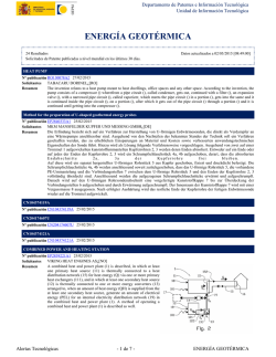
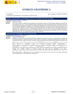
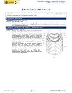
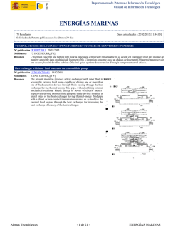
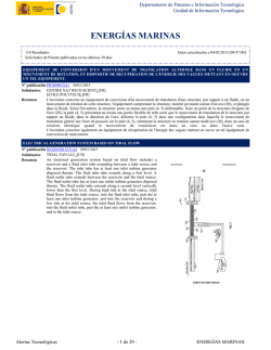
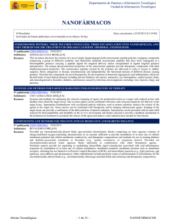
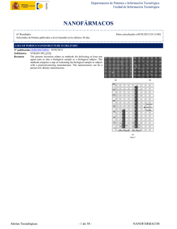
Departamento de Patentes e Información Tecnológica
Unidad de Información Tecnológica
ENERGÍA SOLAR TÉRMICA DE CONCENTRACIÓN
124 Resultados
Solicitudes de Patente publicadas en los últimos 15 días
Datos actualizados a 28/12/2015 [14:47:00]
SOLAR CELL DEVICE
Nº publicación EP2958230A1 23/12/2015
KYOCERA CORP¿[JP]
Solicitantes
A solar cell device (X) includes a first solar cell array (1) and a second
Resumen
solar cell array (2) disposed side by side in one direction and each
including a plurality of solar cell modules (10) disposed side by side
along a direction inclined with respect to an installation surface (P)
and a holding member (22) holding an outer circumference of each of
the solar cell modules (10). The solar cell device (X) also includes a
support member (21) disposed between the first solar cell array (1)
and the ground (P) and extending from the first solar cell array (1) to
the ground (P). According to the present invention, in the first solar
cell array (1), a part of the holding member (22) positioned on the
upper side in the inclined direction is fixed to the top portion (211) of
the support member (21), and in the second solar cell array (2), a part
of the holding member (22) positioned on the lower side in the
inclined direction is fixed to a side portion (212) of the support
member (21).
Solar battery assembly support
Nº publicación EP2956970A1 23/12/2015
BYD CO LTD¿[CN]
Solicitantes
The utility model provides a solar battery assembly support,
Resumen
comprising a main rotating shaft rotatable along the latitude direction,
a supporting mechanism supporting a solar battery assembly, an
adjusting mechanism adjusting the inclination angle of the supporting
mechanism in the longitude direction, and vertical columns supporting
the main rotating shaft. The supporting mechanism enables the solar
battery assembly mounted thereon to be divided into an upper part and
a lower part by taking the main rotating shaft as the boundary. The
solar battery assembly of the utility model is divided into the upper
part and the lower part by taking the main rotating shaft as the
boundary. The southward inclination angle of the solar battery
assembly can be calculated based on the latitude and radiation, and the
adjustment angle can be adjusted according to the irradiance in the
spring and autumn. In the east-west direction, the assembly rotates
around the main rotating shaft based on a certain angle so as to enable
a battery piece to face and track the sun. By employing the solar
battery assembly support of the utility model, not only can the torque
of the assembly when rotating around the rotating shaft along the east-west direction be reduced so that the requirements on the
support bearing and driving can be lowered, but also the installation is enabled to be more convenient.
Alertas Tecnológicas
- 1 de 20 -
ENERGÍA SOLAR TÉRMICA DE CONCENTRACIÓN
Departamento de Patentes e Información Tecnológica
Unidad de Información Tecnológica
Solar cell support system
Nº publicación EP2956971A1 23/12/2015
BYD CO LTD¿[CN]
Solicitantes
The utility model discloses a solar cell support system. The solar cell
Resumen
support system comprises a drive device, a push rod, a plurality of
columns of cross beams, a plurality of vertical columns, a plurality of
vertical column supports, and cell panels, wherein the push rod is
driven by the drive device to move along the length direction of the
drive device; each column of the cross beams is connected with the
push rod via swing rods, the extension directions of the cross beams
are vertically intersected with the push rod, the cross beams form
hollow tubes, and the wall thickness of each column of the cross
beams is gradually reduced along a direction form the intersection
with the push rod to the both ends of each cross beam; and each
column of the cross beams is supported by the plurality of vertical
columns, and capable of rotating on the upper ends of the vertical
columns with the horizontal movement of the push rod; and a plurality
of the cell panels are supported on each column of the cross beams
respectively. According to the solar cell support system disclosed by
the utility model, on the premise of avoiding influence on the stability
of the whole cross beam square matrix, materials are saved, the weight
of the whole square matrix is reduced, the probability of foundation
settlement is decreased, and the stability of the system is improved;
and the solar cell support system is suitable for large-scale surface
power station construction.
Geothermal heat exchanger circuit
Nº publicación EP2957841A1 23/12/2015
DYNAMIC BLUE HOLDING GMBH¿[DE]
Solicitantes
The earth probe system (1) has an influx pipe, which has an influx
Resumen
pipe inner surface looking to the influx pipe, and an influx pipe outer
surface that facing to soil (25). An exhaust pipe is provided, which has
an exhaust pipe inner surface looking to the exhaust pipe. A unit is
provided for the turbulence of a heat transmission liquid in a heat
transmission area.
Alertas Tecnológicas
- 2 de 20 -
ENERGÍA SOLAR TÉRMICA DE CONCENTRACIÓN
Departamento de Patentes e Información Tecnológica
Unidad de Información Tecnológica
PLUG-IN SYSTEM FOR COVERING A SURFACE OF AN OBJECT
Nº publicación EP2956599A1 23/12/2015
LUDWIG THOMAS¿[DE]
Solicitantes
The invention relates to a plug-in system for covering a surface of an
Resumen
object, comprising a first plate (10) that is designed, on one of its
sides, to be secured to said object surface and that has, on its other
side, a plurality of elevations (20) that are arranged parallel to one
another and extend across the plate surface, each set of adjacent
elevations (20) forming a first receiving portion (30) on the first plate
(10); as well as a second plate which carries a decoration or is
designed to receive a decoration or a further covering element on one
of its sides, and has a plurality of elevations on its other side that are
arranged parallel to one another and extend across the plate surface,
the elevations of the second plate being able to connect form-fittingly
to the receiving portions (30) that are located on the first plate (10),
and each set of adjacent elevations on the second plate forming a
second receiving portion for form-fittingly connecting to the
elevations (20) of the first plate (10). The invention is characterised in
that a channel (40) is designed in each of the elevations (20) of the
first plate (10) and/or the elevations of the second plate, and extends
through said elevations (20) for the purpose of receiving a thermal
fluid, a first connection is provided on the first plate (10) and/or the
second plate for conducting the thermal fluid into at least one channel
(40), and a second connection is provided for discharging the thermal
fluid from said at least one channel (40).
HEAT EXCHANGE NANOFLUID
Nº publicación ES2554651A1 22/12/2015
UNIV JAUME I DE CASTELLO¿[ES]
Solicitantes
The present invention relates to a nanofluid comprising an organic
Resumen
synthetic oil which is a polyphenyl, nanoparticles comprising carbon,
and at least one sulfone.
Alertas Tecnológicas
- 3 de 20 -
ENERGÍA SOLAR TÉRMICA DE CONCENTRACIÓN
Departamento de Patentes e Información Tecnológica
Unidad de Información Tecnológica
ENERGY STORAGE METHOD AND SYSTEM FOR STORING ENERGY
Nº publicación WO2015189452A1 17/12/2015
UNIV MADRID CARLOS III¿[ES]
Solicitantes
UNIV POLITÉCNICA DE MADRID¿[ES]
The invention describes an energy-storage system which is based on the phenomenon of sorption/desorption of a vapour in a
Resumen
sorbent, and includes: a) a first thermally insulated tank (2) which houses a sorbent having an affinity for a vapour; b) a second
thermally insulated tank (3) which also houses a sorbent having an affinity for said vapour; c) a compressor device (4) connected
between the first tank (2) and the second tank (3) in order to compress the vapour by making same pass from the first tank (2) to
the second tank (3) in an energy-accumulation phase; and d) an expander device (5) connected between the first tank (2) and the
second tank (3) in order to expand the vapour, enabling same to return from the second tank (3) to the first tank (2) in an
energy-depletion phase.
Solarkollektorvorrichtung und Verfahren zu dessen Montage
Nº publicación DE102014210681A1 17/12/2015
BOSCH GMBH ROBERT¿[DE]
Solicitantes
Die Erfindung betrifft eine Solarkollektorvorrichtung (1) mit wenigstens zwei Fluidröhren (11, 31) und einem Montagegestell
Resumen
(20), wobei das Montagegestell (20) einen rechteckigen Montagerahmen (21) umfassend zwei Längsstreben (22, 23) und zwei
Querstreben (24, 25) sowie eine Rahmenoberseite (26) und eine Rahmenunterseite (27) aufweist, wobei die zwei Fluidröhren (11,
31) am Montagegestell (20) angebunden sind, und wobei die zwei Querstreben (24, 25) fluidführend ausgebildet und die
Fluidröhren (11, 31) jeweils mit den Querstreben (24, 25) strömungsverbunden sind.; Ausserdem betrifft die Erfindung ein
Verfahren zur Montage einer solchen Solarkollektorvorrichtung (1), wobei die Montage des Montagegestells (20) an einem
Aufstellungsort der Solarkollektorvorrichtung (1) durch Ausrichtung und Festlegung des Montagerahmens (21) mittels
wenigstens eines Befestigungsmittels (28) erfolgt, bevor die Fluidröhren (11, 31) am Montagerahmen (21) derart positioniert und
festgelegt werden, dass die Fluidröhren (11, 31) jeweils mit den Querstreben (24, 25) strömungsverbunden sind.
METHOD FOR PRODUCING A SOLAR COLLECTOR
Nº publicación DE102014210674A1 17/12/2015
BOSCH GMBH ROBERT¿[DE]
Solicitantes
Solarkollektor (16) und Verfahren zum Herstellen eines
Resumen
Solarkollektors mit einem Gehäuse (1) und einem Absorber (8), wobei
Partikel (6) in das Gehäuse gefüllt werden und der Absorber (8) in
eine Schicht aus Partikeln (6) gelegt wird, wobei die Partikel durch
Schwingungen des Absorbers (8) und/oder Gehäuses (1) verdichtet
werden und somit eine dicht gepackte Schicht (5, 12) aus den
Partikeln (6) erhalten wird, in die der Absorber (8) eingebettet und
positioniert ist.
Alertas Tecnológicas
- 4 de 20 -
ENERGÍA SOLAR TÉRMICA DE CONCENTRACIÓN
Departamento de Patentes e Información Tecnológica
Unidad de Información Tecnológica
Zweistufiges Konzentratorsystem für einen Paraboloidkollektor
Nº publicación DE102014008794A1 17/12/2015
GRIMM FRIEDRICH¿[DE]
Solicitantes
HERKOMMER ALOIS¿[DE]
Die Erfindung betrifft einen photovoltaischen und solarthermischen Sonnenkollektor (1) mit einer Symmetrieachse (O),
Resumen
bestehend aus einer ersten Konzentratorstufe (10), die von einer auf einen Brennpunkt (F) fokussierenden Parabolschüssel (100)
oder von einem auf einen Brennring (R) fokussierenden Parabolringspiegel (101) oder von einer auf einen Brennpunkt (F) oder
einen Brennring (R) fokussierenden Fresnellinse (102) gebildet wird, und aus einer zweiten Konzentratorstufe (11) und aus einem
Wärmeübertrager (2), der an seiner Oberfläche PV-Zellen (12) trägt.; Die erste Konzentratorstufe (10), die zweite
Konzentratorstufe (11) und der Wärmeübertrager (2) sind jeweils rotationssymmetrisch zu der Symmetrieachse (O) angeordnet,
bilden untereinander eine in sich unverdrehbare Einheit und bündeln bei zweiachsiger Nachführung des Sonnenkollektors (1) um
die Drehachsen (x, y) zum jeweiligen Stand der Sonne die tages- und jahreszeitlich in unterschiedlichen Winkeln einfallenden
parallelen Strahlen (Sp) auf den Wärmeübertrager (2).; Erfindungsgemäss weist die zweite Konzentratorstufe (11) einen
Linsenring (110) oder einen Prismenring (111) auf, der die von der ersten Konzentratorstufe (10) zentrierten Strahlen (Sz) in
mindestens einem konvergenten Strahlenbündel (Sk) auf mindestens einen Brennring (r1) oder in einer Vielzahl von
konvergenten Strahlenbündeln (Sk) auf eine Vielzahl von Brennringen (r1-rn) an der Oberfläche des Wärmeübertragers (2)
fokussiert, wobei die Brennringe (r1-rn) mit einem radialen Abstand konzentrisch zu dem Brennpunkt (F) oder dem Brennring
(R) der ersten Konzentratorstufe (10) angeordnet sind und die Arbeitsflächen der PV-Zellen (12) auf den Brennringen (r1-rn)
liegen.
Vorrichtung zum Halten von Solarmodulrahmen
Nº publicación DE102014007971A1 17/12/2015
SCHLETTER GMBH¿[DE]
Solicitantes
Die Erfindung betrifft eine Vorrichtung zum Halten von Solarmodulrahmen, die nach innen ragenden Rahmenunterseiten und
Resumen
dazu rechtwinkligen Rahmenaussenseiten haben, wobei die Vorrichtung einen Rahmenträger (1) und ein Hakenelement (2)
aufweist, und der Rahmenträger (1) einen ersten Stützschenkel (3) umfasst zum Tragen der nach innen ragenden
Rahmenunterseite (RU) eines solchen Solarmodulrahmens (R), und das Hakenelement (2) verschiebbar an dem Rahmenträger (1)
angeordnet ist zum Hintergreifen der nach innen ragenden Rahmenunterseite (RU).; Dabei ist vorgesehen, dass der Rahmenträger
(I) einen zweiten Stützschenkel (5) aufweist zum Abstützen der senkrechten Rahmenaussenseite (RA) des Solarmodulrahmens
(R), und das Hakenelement (2) in einer Schliessrichtung (4) zu dem zweiten Stützschenkel (5) verschiebbar ist, und zwischen dem
Rahmenträger (1) und dem Hakenelement (2) eine Rastverbindung (6a, 6b) mit mehreren hintereinandergeschalteten
Fügepositionen angeordnet ist, die eine Verschiebung des Hakenelements (2) in die Schliessrichtung (4) zulassen und gegen die
Schliessrichtung (4) sperren.
Alertas Tecnológicas
- 5 de 20 -
ENERGÍA SOLAR TÉRMICA DE CONCENTRACIÓN
Departamento de Patentes e Información Tecnológica
Unidad de Información Tecnológica
CONSTRUCTION ELEMENT HAVING A CONTROLLABLE HEAT-TRANSFER COEFFICIENT U
Nº publicación US2015361654A1 17/12/2015
BASF SE¿[DE]
Solicitantes
FRAUNHOFER GES ZUR FÖRDERUNG DER ANGEWANDTEN FORSCHUNG E V¿[DE]
FRAUNHOFER INST ISE FÜR SOLARE ENERGIESYSTEM¿[DE]
The present invention relates to a construction element (1) having a
Resumen
controllable heat-transfer coefficient U, comprising - a frame (7), - a
first panel (3) and a second panel (5), which are opposite each other
and which are arranged at a distance A from each other in the frame
(7), wherein a closed volume V that is filled with at least one gas is
defined by the first panel (3), the second panel (5), and the frame (7), at least one planar element (9), the width of which corresponds to the
vertical clear width W of the frame (7) and the height of which is less
than the clear height H of the frame (7), wherein the planar element
(9) is arranged between the first panel (3) and the second panel (5) in
such a manner that the planar element ends laterally at the insides of
the frame (7), and wherein an upper intermediate space (11) is formed
between the planar element (9) and the frame (7); vertically upward
and a lower intermediate space (13) is formed between the planar
element (9) and the frame (7) vertically downward, - a first cavity
(15), which is formed between the first panel (3) and the planar
element (9) having a distance X, - a second cavity (17), which is
formed between the planar element (9) and the second panel (5)
having a distance Y, wherein the first cavity (15) and the second
cavity (17) are connected by means of the upper intermediate space
(11) and the lower intermediate space (13) in such a manner that a
convection flow can flow between the first cavity (15) and the second
cavity (17) via the upper intermediate space (11) and the lower
intermediate space (13), - at least one means for controlling the
convection flow, said means being arranged for the upper intermediate
space (11) and/or for the lower intermediate space (13). The present
invention further relates to the use of the construction element (1)
according to the invention as a wall element and/or roof element in
buildings and to a method for controlling the heat-transfer coefficient
U in a construction element (1) according to the invention.
Alertas Tecnológicas
- 6 de 20 -
ENERGÍA SOLAR TÉRMICA DE CONCENTRACIÓN
Departamento de Patentes e Información Tecnológica
Unidad de Información Tecnológica
Fastening system for mounting solar modules
Nº publicación US2015362002A1 17/12/2015
MOUNTING SYSTEMS GMBH¿[DE]
Solicitantes
The profiled rail (100) has a base plate (110) that is provided with a
Resumen
flat bottom surface. A first receiving space (120) and a second
receiving space (130) are set with lateral apertures (171) facing in
opposite directions. A third receiving space (170) is set in form of
hammer head groove to which an aperture is turned away from
underside of main portion. The first and second receiving spaces are
enclosed by cavity sides and are arranged opposite to each other. The
third receiving space is arranged adjacent to first and second receiving
spaces. Independent claims are included for the following: (1) a clip
holder; (2) a cross jointer; and (3) a mounting system for assembly of
solar modules.
IMPROVED SOLAR RECEIVER CONFIGURATION
Nº publicación US2015362218A1 17/12/2015
ALSTOM TECHNOLOGY LTD¿[CH]
Solicitantes
A solar receiver configuration (receiver) adapted to include a plurality
Resumen
of receiver heat transfer passes. Each pass includes a plurality of
panels. Further, each panel includes a plurality of tubes, tangentially
arranged, vertically extending between horizontally placed lower and
upper headers. The headers, which are pipe assemblies with closed
ends, of adjacent panels are horizontally and vertically offset one to
another to form a substantially continuous tube surface. Such
continuous tube surface enables solar heating of the fluid flow
therefrom in at least a parallel flow arrangement and a serpentine flow
arrangement.
Alertas Tecnológicas
- 7 de 20 -
ENERGÍA SOLAR TÉRMICA DE CONCENTRACIÓN
Departamento de Patentes e Información Tecnológica
Unidad de Información Tecnológica
OVER-TEMPERATURE PROTECTION FOR FLOWING FLUID SYSTEMS
Nº publicación US2015362219A1 17/12/2015
WEHNER THOMAS RICHARD¿[US]
Solicitantes
The present invention keeps fluid temperature at a point in a flowing
Resumen
fluid system below a preset limit by providing automatic
self-adjusting over-temperature protection that cools the fluid when
needed and without requiring a separate cold fluid source. The present
invention keeps the temperature of the fluid at a point in the system
clipped at a cutoff temperature and prevents overcooling the fluid.
When the fluid temperature is below the cutoff temperature, the
temperature of the fluid is unchanged as it passes through the
apparatus of the present invention. The present invention can operate
without electrical power or any power source, can function in any
orientation, and works for both unpressurized and pressurized
systems.; The present invention has application in the areas of solar
thermal energy systems, fluid storage tanks, engine oil and coolant
systems, transmission oil systems, hydraulic systems, and cutting oil
systems, among others.
Fastening system for mounting solar modules
Nº publicación US2015362220A1 17/12/2015
MOUNTING SYSTEMS GMBH¿[DE]
Solicitantes
The profiled rail (100) has a base plate (110) that is provided with a
Resumen
flat bottom surface. A first receiving space (120) and a second
receiving space (130) are set with lateral apertures (171) facing in
opposite directions. A third receiving space (170) is set in form of
hammer head groove to which an aperture is turned away from
underside of main portion. The first and second receiving spaces are
enclosed by cavity sides and are arranged opposite to each other. The
third receiving space is arranged adjacent to first and second receiving
spaces. Independent claims are included for the following: (1) a clip
holder; (2) a cross jointer; and (3) a mounting system for assembly of
solar modules.
Alertas Tecnológicas
- 8 de 20 -
ENERGÍA SOLAR TÉRMICA DE CONCENTRACIÓN
Departamento de Patentes e Información Tecnológica
Unidad de Información Tecnológica
MODULE ATTACHMENT APPARATUS AND METHOD
Nº publicación US2015365044A1 17/12/2015
SUNRUN SOUTH LLC¿[US]
Solicitantes
Exemplary systems and methods described herein can be used to secure a rail to a module or the rail to a support using a nut that
Resumen
can be inserted at a desired point of mounting. Another exemplary system describes a flashing to be inserted under a roof shingle,
wherein the flashing is secured to a support for a rail or module. Yet another exemplary system describes a clamp that secures a
rail or module and is adjustable along the length of a post. Spacers can be added to the post to extend the adjustment range of the
clamp.
SOLAR HEAT COLLECTION SYSTEM
Nº publicación ES2554282A2 17/12/2015
MITSUBISHI HITACHI POWER SYS LTD¿[JP]
Solicitantes
In order to reduce the risk of damage to heat exchanger tubes of a
Resumen
high-temperature heat collection device, this solar heat collection
system is provided with a low-temperature heat collection device (1)
which heats supplied water with solar heat to generate steam, a
brackish water separation device (4) which separates a water-steam
two-phase fluid generated in the low-temperature heat collection
device into water and steam, a high-temperature heat collection device
(5) which heats the steam separated by the brackish water separation
device (4) with solar heat reflected by multiple heliostats (8) to
generate superheated steam, and a heliostat control device (13); which
controls the angle of the heliostats such that the metal temperature of
the high-temperature heat collection device is less than or equal to a
threshold temperature set in order to prevent overshoot of the steam
temperature at the outlet of the high-temperature heat collection
device.
Alertas Tecnológicas
- 9 de 20 -
ENERGÍA SOLAR TÉRMICA DE CONCENTRACIÓN
Departamento de Patentes e Información Tecnológica
Unidad de Información Tecnológica
ENERGY STORAGE METHOD AND SYSTEM FOR STORING ENERGY
Nº publicación ES2554133A1 16/12/2015
UNIV MADRID CARLOS III¿[ES]
Solicitantes
UNIV MADRID POLITECNICA¿[ES]
The invention describes an energy-storage system which is based on
Resumen
the phenomenon of sorption/desorption of a vapour in a sorbent, and
includes: a) a first thermally insulated tank (2) which houses a sorbent
having an affinity for a vapour; b) a second thermally insulated tank
(3) which also houses a sorbent having an affinity for said vapour; c) a
compressor device (4) connected between the first tank (2) and the
second tank (3) in order to compress the vapour by making same pass
from the first tank (2) to the second tank (3) in an
energy-accumulation phase; and d) an expander device (5) connected
between the first tank (2) and the second tank (3) in order to expand
the vapour, enabling same to return from the second tank (3) to the
first tank (2) in an energy-depletion phase.
CN204880913U
Nº publicación CN204880913U 16/12/2015
CN204880867U
Nº publicación CN204880867U 16/12/2015
CN204880831U
Nº publicación CN204880831U 16/12/2015
CN204880830U
Nº publicación CN204880830U 16/12/2015
CN204880829U
Nº publicación CN204880829U 16/12/2015
CN204880828U
Nº publicación CN204880828U 16/12/2015
CN204880827U
Nº publicación CN204880827U 16/12/2015
CN204880826U
Nº publicación CN204880826U 16/12/2015
CN204880825U
Nº publicación CN204880825U 16/12/2015
CN204880824U
Nº publicación CN204880824U 16/12/2015
Alertas Tecnológicas
- 10 de 20 -
ENERGÍA SOLAR TÉRMICA DE CONCENTRACIÓN
Departamento de Patentes e Información Tecnológica
Unidad de Información Tecnológica
CN204880823U
Nº publicación CN204880823U 16/12/2015
CN204880822U
Nº publicación CN204880822U 16/12/2015
CN204880821U
Nº publicación CN204880821U 16/12/2015
CN204880819U
Nº publicación CN204880819U 16/12/2015
CN204880818U
Nº publicación CN204880818U 16/12/2015
CN204880817U
Nº publicación CN204880817U 16/12/2015
CN204880816U
Nº publicación CN204880816U 16/12/2015
CN204880815U
Nº publicación CN204880815U 16/12/2015
CN204880814U
Nº publicación CN204880814U 16/12/2015
CN204880813U
Nº publicación CN204880813U 16/12/2015
CN204880812U
Nº publicación CN204880812U 16/12/2015
CN204880811U
Nº publicación CN204880811U 16/12/2015
CN204880810U
Nº publicación CN204880810U 16/12/2015
CN204880809U
Nº publicación CN204880809U 16/12/2015
CN204880808U
Nº publicación CN204880808U 16/12/2015
CN204880807U
Nº publicación CN204880807U 16/12/2015
CN204880806U
Nº publicación CN204880806U 16/12/2015
CN204880805U
Nº publicación CN204880805U 16/12/2015
CN204880804U
Nº publicación CN204880804U 16/12/2015
CN204880803U
Nº publicación CN204880803U 16/12/2015
Alertas Tecnológicas
- 11 de 20 -
ENERGÍA SOLAR TÉRMICA DE CONCENTRACIÓN
Departamento de Patentes e Información Tecnológica
Unidad de Información Tecnológica
CN204880802U
Nº publicación CN204880802U 16/12/2015
CN204880801U
Nº publicación CN204880801U 16/12/2015
CN204880800U
Nº publicación CN204880800U 16/12/2015
CN204880799U
Nº publicación CN204880799U 16/12/2015
CN204880798U
Nº publicación CN204880798U 16/12/2015
CN204880797U
Nº publicación CN204880797U 16/12/2015
CN204880796U
Nº publicación CN204880796U 16/12/2015
CN204880794U
Nº publicación CN204880794U 16/12/2015
CN204880793U
Nº publicación CN204880793U 16/12/2015
CN204880792U
Nº publicación CN204880792U 16/12/2015
CN204880791U
Nº publicación CN204880791U 16/12/2015
CN204880790U
Nº publicación CN204880790U 16/12/2015
CN204880789U
Nº publicación CN204880789U 16/12/2015
CN204880788U
Nº publicación CN204880788U 16/12/2015
CN204880787U
Nº publicación CN204880787U 16/12/2015
CN204880786U
Nº publicación CN204880786U 16/12/2015
CN204880785U
Nº publicación CN204880785U 16/12/2015
CN204880784U
Nº publicación CN204880784U 16/12/2015
CN204880783U
Nº publicación CN204880783U 16/12/2015
CN204880782U
Nº publicación CN204880782U 16/12/2015
Alertas Tecnológicas
- 12 de 20 -
ENERGÍA SOLAR TÉRMICA DE CONCENTRACIÓN
Departamento de Patentes e Información Tecnológica
Unidad de Información Tecnológica
CN204880781U
Nº publicación CN204880781U 16/12/2015
CN204880780U
Nº publicación CN204880780U 16/12/2015
CN204880779U
Nº publicación CN204880779U 16/12/2015
CN204880778U
Nº publicación CN204880778U 16/12/2015
CN204880777U
Nº publicación CN204880777U 16/12/2015
CN204880776U
Nº publicación CN204880776U 16/12/2015
CN204880775U
Nº publicación CN204880775U 16/12/2015
CN204880774U
Nº publicación CN204880774U 16/12/2015
CN204880772U
Nº publicación CN204880772U 16/12/2015
CN204880771U
Nº publicación CN204880771U 16/12/2015
CN204880770U
Nº publicación CN204880770U 16/12/2015
CN204880753U
Nº publicación CN204880753U 16/12/2015
CN204880744U
Nº publicación CN204880744U 16/12/2015
CN204880501U
Nº publicación CN204880501U 16/12/2015
CN204880329U
Nº publicación CN204880329U 16/12/2015
CN204879448U
Nº publicación CN204879448U 16/12/2015
CN204879078U
Nº publicación CN204879078U 16/12/2015
CN204876389U
Nº publicación CN204876389U 16/12/2015
CN204876386U
Nº publicación CN204876386U 16/12/2015
CN204876213U
Nº publicación CN204876213U 16/12/2015
Alertas Tecnológicas
- 13 de 20 -
ENERGÍA SOLAR TÉRMICA DE CONCENTRACIÓN
Departamento de Patentes e Información Tecnológica
Unidad de Información Tecnológica
CN204873910U
Nº publicación CN204873910U 16/12/2015
CN204865027U
Nº publicación CN204865027U 16/12/2015
CN204865026U
Nº publicación CN204865026U 16/12/2015
CN204862690U
Nº publicación CN204862690U 16/12/2015
CN204860358U
Nº publicación CN204860358U 16/12/2015
Modification of UV Absorption Profile of Polymer Film Reflectors to Increase Solar-Weighted Reflectance
Nº publicación CN105164914A 16/12/2015
Provided are reflective thin film constructions including a reduced
Resumen
number of layers, which provides for increased solar-weighted
hemispherical reflectance and durability. Reflective films include
those comprising an ultraviolet absorbing abrasion resistant coating
over a metal layer. Also provided are ultraviolet absorbing abrasion
resistant coatings and methods for optimizing the ultraviolet
absorption of an abrasion resistant coating. Reflective films disclosed
herein are useful for solar reflecting, solar collecting, and solar
concentrating applications, such as for the generation of electrical
power.
Alertas Tecnológicas
- 14 de 20 -
ENERGÍA SOLAR TÉRMICA DE CONCENTRACIÓN
Departamento de Patentes e Información Tecnológica
Unidad de Información Tecnológica
MOUNTING STRUCTURES FOR PHOTOVOLTAIC CELLS
Nº publicación CN105164817A 16/12/2015
Mounting systems for PV modules and assemblies of modules,
Resumen
including apparatus and methods of use. The disclosed systems
generally involve mounting a flexible photovoltaic module in a slight
arch, bending it with a large radius around one axis of the module.
CN105157261A
Nº publicación CN105157261A 16/12/2015
CN105157260A
Nº publicación CN105157260A 16/12/2015
CN105157259A
Nº publicación CN105157259A 16/12/2015
CN105157258A
Nº publicación CN105157258A 16/12/2015
CN105157257A
Nº publicación CN105157257A 16/12/2015
CN105157256A
Nº publicación CN105157256A 16/12/2015
CN105157255A
Nº publicación CN105157255A 16/12/2015
CN105157254A
Nº publicación CN105157254A 16/12/2015
CN105157252A
Nº publicación CN105157252A 16/12/2015
CN105157251A
Nº publicación CN105157251A 16/12/2015
Alertas Tecnológicas
- 15 de 20 -
ENERGÍA SOLAR TÉRMICA DE CONCENTRACIÓN
Departamento de Patentes e Información Tecnológica
Unidad de Información Tecnológica
CN105157250A
Nº publicación CN105157250A 16/12/2015
CN105157248A
Nº publicación CN105157248A 16/12/2015
CN105157247A
Nº publicación CN105157247A 16/12/2015
CN105157246A
Nº publicación CN105157246A 16/12/2015
CN105157245A
Nº publicación CN105157245A 16/12/2015
CN105157244A
Nº publicación CN105157244A 16/12/2015
CN105157243A
Nº publicación CN105157243A 16/12/2015
CN105156144A
Nº publicación CN105156144A 16/12/2015
CN105157249A
Nº publicación CN105157249A 16/12/2015
IMPROVED SOLAR RECEIVER CONFIGURATION
Nº publicación EP2955461A1 16/12/2015
ALSTOM TECHNOLOGY LTD¿[CH]
Solicitantes
A solar receiver configuration (receiver) adapted to include a plurality of receiver heat transfer passes. Each pass includes a
Resumen
plurality of panels. Further, each panel includes a plurality of tubes, tangentially arranged, vertically extending between
horizontally placed lower and upper headers. The headers, which are pipe assemblies with closed ends, of adjacent panels are
horizontally and vertically offset one to another to form a substantially continuous tube surface. Such continuous tube surface
enables solar heating of the fluid flow therefrom in at least a parallel flow arrangement and a serpentine flow arrangement.
Alertas Tecnológicas
- 16 de 20 -
ENERGÍA SOLAR TÉRMICA DE CONCENTRACIÓN
Departamento de Patentes e Información Tecnológica
Unidad de Información Tecnológica
REFLECTING MIRROR FOR SOLAR LIGHT COLLECTION
Nº publicación EP2955549A1 16/12/2015
FUJIFILM CORP¿[JP]
Solicitantes
The purpose of the present invention is to provide a reflecting mirror
Resumen
for solar light collection having excellent scratch resistance as well as
excellent ease of installation and release. This reflecting mirror for
solar light collection has a resin substrate, a polygonal film mirror for
solar light collection having a metal reflecting layer and a surface
coating layer, and a frame-shaped support member for supporting a
peripheral edge part of the film mirror.
Solar Automatic soaking and gathering-heat pipe, slot-typed assembly, thermal power generating system and craft
Nº publicación EP2955460A1 16/12/2015
ZHONGYING CHANGJIANG INTERNAT NEW ENERGY INVEST CO LTD¿[CN]
Solicitantes
The invention relates to a solar automatic soaking and gathering-heat
Resumen
pipe, a slot-typed assembly, a thermal power generating system and a
craft. The solar automatic soaking and gathering-heat pipe comprises a
glass tube and an absorption tube which is installed inside the glass
tube and is coated with an endothermic layer. Vacuum is arranged
between the glass tube and the absorption tube. The solar automatic
soaking and gathering-heat pipe is characterized in that segregation
board which is used for enabling fluid to turn flow up and down
alternatively in the absorption tube and is installed inside the inner
chamber of the absorption tube. The segregation board is in a
heliciform and is fixed in the absorption tube enabling the solar
automatic soaking and gathering-heat pipe to be filled with water to
heat directly without the worry of booster.; Meanwhile, the electrical
power generating system and the craft through photo-thermal
supplementary electricity generation enables the photo-thermal
supplementary power station to be unaffected by the weather so that
the electricity can be generated steadily at night or when the sunlight
is inadequate. Energy conservation and environment protection can be
achieved.
Alertas Tecnológicas
- 17 de 20 -
ENERGÍA SOLAR TÉRMICA DE CONCENTRACIÓN
Departamento de Patentes e Información Tecnológica
Unidad de Información Tecnológica
SYSTEMS AND METHODS FOR PROVIDING SUPPLEMENTAL AQUEOUS THERMAL ENERGY
Nº publicación EP2954205A1 16/12/2015
ADVANCED GREEN TECHNOLOGIES LLC¿[US]
Solicitantes
Systems and methods for collecting, storing, and conveying aqueous
Resumen
thermal energy are disclosed. In a particular embodiment, a floating
film retains solar energy in a volume of water located under the film.
A series of curtains hanging from a bottom surface of the film define a
passage between a periphery of the film and a center of the film to
direct the heated water at the center of the film. The heated water is
circulated to deliver the heat to a dissociation reactor and/or donor
substance. The donor is conveyed to the reactor and dissociated.
SOLAR FACILITY WITH A PLURALITY OF IN-LINE TRACKER SUPPORT SYSTEMS
Nº publicación EP2954267A1 16/12/2015
OPTIMUM TRACKER¿[FR]
Solicitantes
A linear solar facility (1) comprising at least two tracker support
Resumen
systems (2) for solar collectors, in which each tracker support system
(2) can be oriented according to a main axis of rotation (20) with the
tracker support systems (2) aligned along a same line with the main
axes of rotation (20) of same being merged, in which each tracker
support system (2) comprises: a fixed ground-anchoring structure
(21); a mobile structure comprising a platform (22) for supporting the
solar collectors, rotatably mounted on the fixed structure (21)
according to the main axis of rotation (20); a mechanical drive system
(24) for driving the mobile structure in rotation according to the main
axis of rotation (20). The facility comprises an actuating system (3)
shared by the tracker support systems (2), coupled to the mechanical
drive systems (24) of same via a mechanical transmission device (4)
that extends parallel to the main axis of rotation, such that the
platforms (22) are driven in rotation concomitantly by said actuating
system (3) via the transmission device (4) and the mechanical drive
systems (24).
Alertas Tecnológicas
- 18 de 20 -
ENERGÍA SOLAR TÉRMICA DE CONCENTRACIÓN
Departamento de Patentes e Información Tecnológica
Unidad de Información Tecnológica
TRACKING PHOTOVOLTAIC SOLAR SYSTEM, AND METHODS FOR INSTALLING OR FOR USING SUCH TRACKING
PHOTOVOLTAIC SOLAR SYSTEM
Nº publicación EP2954266A1 16/12/2015
HELIOSLITE¿[FR]
Solicitantes
MENARD ETIENNE¿[FR]
A tracking photovoltaic solar system, and methods for installing or for
Resumen
using such tracking comprising at least a dual axis tracker unit
maintaining an array of photovoltaic modules aligned to the sun. Said
tracker unit includes :a pair of sub-frames supporting photovoltaic
modules, a torque tube supporting said sub-frames rotating around a
primary rotation axis, a pole structure fixed and extending vertically
above an anchoring basis and being rotatively connected to said
longitudinal support, secondary rotating means controlling the
orientation of said sub-frames around corresponding secondary
rotation axis of said sub- frames, said secondary rotation axis being
orthogonal to said primary rotation axis and actuators means for
controlling said primary and secondary rotating means. The secondary
rotation axis are located at each end of said torque tube, said pole
structure being central with regard to said sub-frames and said
actuators means of both primary and secondary rotating means are
linear.
RECEIVER FOR SOLAR PLANTS AND SOLAR PLANT
Nº publicación EP2954264A1 16/12/2015
SUNOYSTER SYSTEMS GMBH¿[DE]
Solicitantes
The invention relates to a receiver (4) for mounting in the focal line of
Resumen
a solar collector (1) having a linear focusing mirror element (3). The
receiver (4) has an elongate hollow profile (10) with a duct (11) for
heat transfer fluid, and solar cells (12) on one side of the hollow
profile (10) for converting solar radiation into electrical energy. The
solar cells (12) and the hollow profile (10) are heat-conductively
connected and mounted in a transparent protective tube (13). Between
the protective tube (13) and the solar cells (12) is at least one
beam-manipulating element, and the hollow profile (10), solar cells
(12), protective tube (13) and beam-manipulating element of the
receiver (4) are positioned in fixed relation to each other. The
invention also relates to a solar plant (1) having a linear focusing
optical element (3) with a receiver (4) mounted in its focal line, and
according to the invention the receiver (4) is designed and arranged so
that the solar cells (12) of the receiver (4) are facing the linear
focusing optical element (3).
Alertas Tecnológicas
- 19 de 20 -
ENERGÍA SOLAR TÉRMICA DE CONCENTRACIÓN
Departamento de Patentes e Información Tecnológica
Unidad de Información Tecnológica
HOUSING FOR PHOTOVOLTAICS
Nº publicación AT515875A1 15/12/2015
TAPPEINER ROLAND¿[AT]
Solicitantes
Gehäuse für ein Photovoltaikgerät, bestehend aus zwei dreieckigen
Resumen
Seitenteilen (2,3), einem Boden (11), einer Rückwand (10) und einem
Photovoltaikpaneel (1) welche in Nuten (21,22,23) der Seitenteile
(2,3)geschoben werden und mittels dreier Stangen (4, 5, 6)
zusammengehalten werden.
FILM MIRROR AND REFLECTION DEVICE FOR SOLAR POWER GENERATION
Nº publicación JPWO2013146980A1 14/12/2015
A film mirror (20a) provided with a silver reflective layer (3) and an
Resumen
acrylic layer (5) on a resin substrate (1), wherein the acrylic layer (5)
contains a compound represented by the general formula (1) below.
(In the formula, R1a, R1b, R1c, R1d, R1e, R1f, R1g, R1h, R1i, R1j,
R1k, R1m, R1n, and R1p are mutually independent and represent
hydrogen atoms or monovalent substituent groups. Also, substituent
groups may bond together to form a ring.)
Alertas Tecnológicas
- 20 de 20 -
ENERGÍA SOLAR TÉRMICA DE CONCENTRACIÓN
© Copyright 2026