
Alertas Tecnológicas
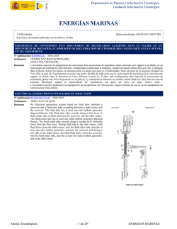
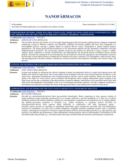
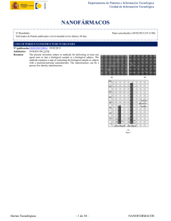
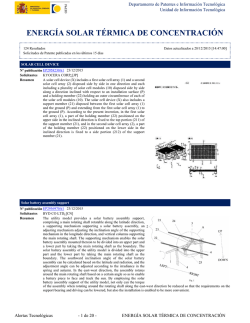
Departamento de Patentes e Información Tecnológica
Unidad de Información Tecnológica
ENERGÍAS MARINAS
79 Resultados
Solicitudes de Patente publicadas en los últimos 30 días
Datos actualizados a 22/02/2015 [11:44:00]
TURBINE, CHASSIS DE LOGEMENT D'UNE TURBINE ET SYSTEME DE CONVERSION D'ENERGIE
Nº publicación FR3009738A1 20/02/2015
P3 INGENIEURS¿[FR]
Solicitantes
L'invention concerne une turbine (20) pour la génération d'électricité remarquable en ce qu'elle est configurée pour être montée de
Resumen
manière amovible dans un châssis de logement (30). L'invention concerne aussi un châssis de logement (30) agencé pour recevoir
une ou une pluralité de telles turbines (20) ainsi qu'un système de conversion d'énergie comprenant un tel châssis.
Heat exchanger with inner fluid to actuate the external fluid pump
Nº publicación US2015047810A1 19/02/2015
YANG TAI-HER¿[TW]
Solicitantes
The present invention provides a heat exchanger with inner fluid to
Resumen
actuate the external fluid pump capable of driving one or more than
one of fluid actuation devices through fluids passing through the heat
exchanger having thermal-energy fluid pipe, without utilizing external
mechanical rotational kinetic energy or power of electric motors
respectively driving external fluid pumping blade devices installed at
lateral sides of the heat exchanger having thermal-energy fluid pipe
with a direct or non-contact transmission means, so as to drive the
external fluid to pass through the heat exchanger for increasing the
heat exchange efficiency of the heat exchanger.
Alertas Tecnológicas
- 1 de 21 -
ENERGÍAS MARINAS
Departamento de Patentes e Información Tecnológica
Unidad de Información Tecnológica
ROTOR BLADE FOR A WATER TURBINE, IN PARTICULAR FOR A TIDAL POWER STATION, AND METHOD FOR
OPERATING SAME
Nº publicación US2015050146A1 19/02/2015
DORWEILER HARALD¿[DE]
Solicitantes
PERNER NORMAN¿[DE]
BISKUP FRANK¿[DE]
The invention relates to a rotor blade for a water turbine having a
Resumen
hydrodynamic profile, with which a suction side and a pressure side is
associated, comprising a plurality of overflow channels that are
arranged in the hydrodynamic profile and that establish a hydraulic
connection between the suction side and the pressure side and with
each of which a valve unit is associated. The invention is
characterized in that the valve unit is closed below a predetermined
maximum load threshold for the rotor blade and open above the
maximum load threshold, wherein, in the open position of the valve
arrangement, each overflow channel reduces the power coefficient
and/or the thrust coefficient of the rotor blade with respect to the
closed position thereof.
Modularized ocean energy power generating device
Nº publicación US2015048619A1 19/02/2015
HANGZHOU LHD INST OF NEW ENERGY LLC¿[CN]
Solicitantes
The utility model provides a modularized ocean energy power
Resumen
generating device, which comprises an outer framework, at least four
inner frameworks and at least four hydraulic turbine generator
modules, wherein the at least four inner frameworks are arranged in
the outer framework in a separable way, and the at least four hydraulic
turbine generator modules are respectively arranged in the four inner
frameworks. The modularized ocean energy power generating device
is provided with at least four built-in modules, and the hydraulic
turbine generator modules can form arrayed arrangement. Through the
arrangement of the separable inner frameworks and outer framework,
the modularized assembly is realized, and the repair and installing cost is greatly reduced.
Steuerung der Rotationsgeschwindigkeit einer rotierenden Wellenenergieanlage in Abhängigkeit von der Strömungsgeschwindigkeit
Nº publicación DE102013216339A1 19/02/2015
BOSCH GMBH ROBERT¿[DE]
Solicitantes
Die Erfindung betrifft ein Verfahren zum Betreiben einer Wellenenergieanlage (1) zur Umwandlung von Energie aus einer
Resumen
Wellenbewegung eines Fluids in eine andere Energieform, wobei die Wellenenergieanlage (1) einen um eine Rotordrehachse (x)
drehbar gelagerten Hebelarm (4), der einen Kopplungskörper (3) trägt, und einen mit dem drehbar gelagerten Hebelarm (4)
gekoppelten Energiewandler (2, 7) aufweist, wobei in einem ersten Betriebsmodus die Wellenenergieanlage (1) so betrieben wird,
dass eine Rotationsgeschwindigkeit ([omega]1) des Hebelarms (4) um die Rotordrehachse (x) im zeitlichen Mittel über eine
Umdrehung einer Orbitalgeschwindigkeit ([Omega]) der Wellenbewegung entspricht, wobei in einem zweiten Betriebsmodus die
Wellenenergieanlage (1) so betrieben wird, dass die Rotationsgeschwindigkeit ([omega]1) des Hebelarms (4) um die
R o t o r d r e h a c h s e
( x )
im zeitlichen Mittel über eine Umdrehung nicht der Orbitalgeschwindigkeit ([Omega]) der Wellenbewegung entspricht, wobei die
Wellenenergieanlage (1) in dem zweiten Betriebsmodus betrieben wird, wenn eine eine Strömungsgeschwindigkeit (v)
kennzeichnende Grösse (H) einen unteren Schwellwert unterschreitet.
Alertas Tecnológicas
- 2 de 21 -
ENERGÍAS MARINAS
Departamento de Patentes e Información Tecnológica
Unidad de Información Tecnológica
ADAPTIVE HYDRAULIC PRESSURE GENERATOR
Nº publicación EP2836713A2 18/02/2015
UNIV AALTO FOUNDATION¿[FI]
Solicitantes
The invention relates to an adaptive hydraulic pressure generator (10)
Resumen
for systems in which the mechanical force producing energy varies
significantly, especially for wave energy systems. The pressure
generator comprises at least two fluid chambers (11, 12
2 0 1 ,
2 0 2
3 0 1 ,
3 0 2 ,
3 0 3
401, 402, 403) with a piston surface/displacement surface (A1y, A1a,
A2y, A2a), which piston surface/displacement surface and fluid
chamber are arranged to reciprocate with respect to one another,
whereby the piston surface/displacement surface (A1y, A1a, A2y,
A2a) acts on the fluid in the chamber (11, 12
2 0 1 ,
2 0 2
3 0 1 ,
3 0 2 ,
3 0 3
401, 402, 403) by means of the said mutual reciprocating movement.
The pressure generator is arranged to produce a pressure exceeding a
certain threshold pressure in the fluid supplied to the application.
The pressure generator (10) is equipped with a control system (18)
which is arranged to connect the chambers to each other and/or to
different pressure ducts in such a way that the effective area (Aeff) of
the piston/displacement surfaces (A1y, A1a, A2y, A2a) changes in
accordance with the changes in the driving force exerted on the
piston/displacement surfaces (A1y, A1a, A2y, A2a) and/or the body
forming the fluid chamber in such a way that the pressure
produced-by the-pressure generator in the fluid supplied to the
application exceeds the threshold pressure.
Device for recovering so-called wave power energy from a swell
Nº publicación EP2837817A1 18/02/2015
WINDECK CLAUDE¿[FR]
Solicitantes
La présente invention concerne l'énergie de la houle récupérée puis
Resumen
transformée en énergie électrique. Une ossature rigide horizontale
semi flottante submergée relie moult systèmes identiques consistant en
un petit flotteur lenticulaire actionnant individuellement un alternateur
électrique spécial à l'aide d'une transformation du mouvement
alternatif vertical en un mouvement rotatif unisens régularisé,
concrétisé par une vis verticale non tournante reliée au dit flotteur, et
par un écrou rotatif relié au dit alternateur électrique. L'ensemble est
quasi totalement immergé, puisque seuls les dits nombreux flotteurs
sont
en
surface
actionnés
par
la
houle.
Les avantages procurés sont les suivants : - Actif même à faible houle
car éléments mobiles de petites dimensions donc très agiles - Sans
appui côtier ni au fond coûteux et difficile à établir - Flottant donc
insensible au marnage et halable, protégé des coups de mer car
submergé Rendement énergétique électro magnétique exceptionnel
Modulaire d'où extensible et facile à construire et à entretenir Léger et
économique Peu visible donc n'affecte que très peu l'image idyllique
de la mer
Alertas Tecnológicas
- 3 de 21 -
ENERGÍAS MARINAS
Departamento de Patentes e Información Tecnológica
Unidad de Información Tecnológica
Tidal current generating device and installation frame thereof
Nº publicación US2015042095A1 12/02/2015
HANGZHOU LHD INST OF NEW ENERGY LLC¿[CN]
Solicitantes
A tidal current generating device comprises an installation frame 1 for
Resumen
supporting tidal turbines 4, the frame including at least two vertically
orientated buoyancy units 2 . The installation frame 1 may hold at
least three hydro turbines 4 and at least one power generation module
(5, figure 3). One or more turbines 4 may be mounted on a detachable
inner frame 3. The buoys 2 may comprise an upper fixed buoyancy,
and a lower body with variable buoyancy (21, 22, figure 3). The
system may include tapered deflectors (203, figure 8) and a lattice
grille 6 to protect the turbines 4
FLEXIBLE WATER TURBINE
Nº publicación US2015042096A1 12/02/2015
MASEK VLASTIMIL¿[CA]
Solicitantes
COOK ANDREW¿[CA]
GENESIS GROUP INC¿[CA]
The invention relates to a water mill, power generator, for use
Resumen
underwater, having a flexible support shaft which permits the water
current to orient the turbine axis substantially parallel to the direction
of flow so that the force of the water on the blades is optimized for a
given turbine, without the need for slip ring style connections between
the generator at the turbine and the5 anchored base. Optionally, the
design features fins or cowlings on the flexible support shaft to further
improve reorientation of the turbine with the water current or flow
acting
as
the
source
of
power
and/or output power links or power conditioning systems at the
anchored base. The generators may be selected to meet low rotation
operating conditions, and the entire system may be designed for
particular ocean bottom and/or current parameters applicable to the10 deployment. The power generator could be used to provide
electrical power to underwater installations for military, security, oceanography, monitoring and oil & gas exploration purposes.
Ocean Thermal Energy Conversion Plant
Nº publicación US2015040563A1 12/02/2015
ABELL FOUNDATION INC¿[US]
Solicitantes
An offshore power generation structure comprising a submerged portion having a first deck portion comprising an integral
Resumen
multi-stage evaporator system, a second deck portion comprising an integral multi-stage condensing system, a third deck portion
housing
power
generation
equipment,
cold
water
pipe
and a cold water pipe connection. The heat exchangers in the evaporator and condenser systems include a multi-stage cascading
heat exchange system. Warm water conduits in the first deck portion and cold water conduits in the second deck portion are
integral to the structure of the submerged portion of the offshore platform.
Alertas Tecnológicas
- 4 de 21 -
ENERGÍAS MARINAS
Departamento de Patentes e Información Tecnológica
Unidad de Información Tecnológica
Power Generating Hydroconveyor
Nº publicación US2015042097A1 12/02/2015
CUNNANE FRANK PATRICK¿[US]
Solicitantes
Hydroconveyors are described which utilize magnetic levitation or
Resumen
magnetic suspension to support a collection of conveyor elements.
The hydroconveyors are located above or partially within a
flowstream such as a river. Additional versions of the hydroconveyors
are described which include velocity increasing waterways located
upstream of an end of the hydroconveyor. The various
hydroconveyors can be used in conjunction with electrical generators
to provide electrical power.
An electro-pneumatic generator
Nº publicación GB2517018A 11/02/2015
F X K PATENTS LTD¿[GB]
Solicitantes
An apparatus generates electrical current using pressure fluctuation in
Resumen
a gas supply valve. A generator 12 may comprise a coil and a magnet,
one of which is attached to a diaphragm 4 or pusher pin 5 of the valve.
Alternatively movement may be transmitted to a piezoelectric member
(figures 6-8). The apparatus may be used with a valve of a breathing
apparatus, e.g. for medical or diving use, in which the valve member
will be continuously moving as the user breathes. The electrical output
may be used e.g. to display a reading of the state of the contents of a
gas cylinder.
Alertas Tecnológicas
- 5 de 21 -
ENERGÍAS MARINAS
Departamento de Patentes e Información Tecnológica
Unidad de Información Tecnológica
Tidal current generating device and installation frame thereof
Nº publicación GB2516989A 11/02/2015
HANGZHOU LHD INST OF NEW ENERGY LLC¿[CN]
Solicitantes
A tidal current generating device comprises an installation frame 1 for
Resumen
supporting tidal turbines 4, the frame including at least two vertically
orientated buoyancy units 2 . The installation frame 1 may hold at
least three hydro turbines 4 and at least one power generation module
(5, figure 3). One or more turbines 4 may be mounted on a detachable
inner frame 3. The buoys 2 may comprise an upper fixed buoyancy,
and a lower body with variable buoyancy (21, 22, figure 3). The
system may include tapered deflectors (203, figure 8) and a lattice
grille 6 to protect the turbines 4
Dispositivo sumergible para aprovechamiento energético de la diferencia de nivel de agua, para un sistema y procedimiento de bombeo,
almacenamiento y turbinado, con el fin de obtención de energía eléctrica
Nº publicación ES2528334A1 06/02/2015
UNIV LA RIOJA¿[ES]
Solicitantes
Dispositivo sumergible (1) que comprende: una campana de fijación por vacío (105) para la fijación del dispositivo sumergible
Resumen
(1)
al
lecho
marino,
lacustre,
o
fluvial
(100)
una carcasa (101), con forma hidrodinámica, dotada de una rejilla inferior (103) y una rejilla superior (102)
una cámara inferior (200) con forma cilíndrica y una cámara superior (201), con forma cilíndrica en su base inferior y en su
cuerpo
central,
y
con
forma
semiesférica
en
su
base
superior
un émbolo (202) con un extremo inferior de forma plana y con un extremo superior de forma semiesférica. La finalidad del
sistema es bombear agua por una tubería de bombeo general (400) hasta un depósito elevado (401) con el fin de mediante una
tubería de turbinado (402) turbinar el agua en una central hidroeléctrica (403).
WAVE ACTIVATED POWER GENERATION SYSTEM WITH RACK & PINION MECHANISM
Nº publicación WO2015015245A1 05/02/2015
NOZAWA TSUKASA¿[JP]
Solicitantes
A
wave
activated
power
generating
device
that
incorporates
a
support
frame
(15)
Resumen
a buoy vertically positioned to rise and fall relative to motion of waves impacting the buoy and the support frame, the buoy being
formed
with
a
hollow
interior
space
a rack and pinion structure operatively connected between the buoy and the support frame such that a pinion element (30) of the
rack and pinion structure generates rotating torque by moving along the rack element (13) in response to the buoy rising and
falling
by
the
wave
motion
and a power generator unit operative connected to the rack and pinion structure to generate electricity in response to rotating
torque generated by the pinion element. The rack structure (13) is fixedly connected to at least one vertical surface inside the
hollow interior space of the buoy. The pinion element is fixedly mounted on the support frame to extend into the hollow interior
space of the buoy.
Alertas Tecnológicas
- 6 de 21 -
ENERGÍAS MARINAS
Departamento de Patentes e Información Tecnológica
Unidad de Información Tecnológica
WAVE POWER CONVERTER
Nº publicación AU2013279831A1 05/02/2015
PATENTSELSKABET AF 30 NOVEMBER 2014 APS
Solicitantes
A wave power converter including a wave power converter housing
Resumen
with a bottom and a top between which there is a distance limiting
structure, and through which there is a central axis, and wherein
entirely or partially outside the wave power converter housing there is
at least one preferably elongated paddle having a longitudinal
direction of a first generatrix and a lower end and an upper end, and
which via a first connection to a first power converter with a rotary
axis at an angle, preferably at right angles, to the central axis and
fastened to the wave power converter housing at the top. The first
power converter interacts via at least one piston rod with at least one
second power converter as a first end of the piston rod via a flexible
joint is fastened to the first power converter, and as a second end of
the piston rod has a piston adapted for a linear movement along a
second generatrix in the at least one second power converter which
includes a linear chamber surrounded by a chamber casing upon
which is provided a rotatable and pivotable connection to the wave
power converter housing at the bottom in continuation of the second
generatrix.
ARRANGEMENT FOR A SELF-LUBRICATING BEARING
Nº publicación AU2012384575A1 05/02/2015
MINESTO AB
Solicitantes
The invention relates to an arrangement (1) for a self-lubricating
Resumen
bearing. The arrangement (1) comprises a fluid bearing (13)
comprising a first fluid bearing element (13a) located in a bearing
housing (12) and a piston (3) located in a pump housing (2). The
bearing housing (12) comprises a bearing housing opening (14). The
pump housing (2) comprises a pump housing opening (7). The first
fluid bearing element (13a) is connected to the piston (3) by means of
a connection means (15) extending from the first fluid bearing element
(13a) through the bearing housing opening (14) to the piston (3)
through the pump housing opening (7). The piston (3) is arranged to
reciprocate in the pump housing (2). The pump housing (2) is
connected to a fluid reservoir by means of a first inlet (10). The
bearing housing (12) comprises a first outlet (19) for allowing fluid to
exit the bearing housing (12). The arrangement (1) further comprises a
fluid transport means fluidly connecting the pump housing (2) and the
bearing housing. A longitudinal movement of the bearing housing (12)
or the pump housing (2) causes the piston (3) to cause a pumping
action, whereby fluid from the fluid reservoir is pumped to the fluid
bearing (13) through the fluid transport means, lubricating the fluid
bearing (13).
Alertas Tecnológicas
- 7 de 21 -
ENERGÍAS MARINAS
Departamento de Patentes e Información Tecnológica
Unidad de Información Tecnológica
Hydraulic pressure type wave energy converter
Nº publicación WO2015014241A1 05/02/2015
CHEN JIASHAN¿[CN]
Solicitantes
The utility model provides a hydraulic pressure type wave energy
Resumen
converter used for converting wave energy into high pressure water
energy. The hydraulic pressure type wave energy converter comprises
mooring facilities such as an upper floating body (1), a lower floating
body (2), a first mooring rope (3), a second mooring rope (4), a
hanging rod (5), a ball hinge hook (6), a seabed anchor pile (7) and the
like, wherein the rectangular upper floating body (1) floats on the
w a t e r
s u r f a c e
the lower floating body (2) adopts a cylindrical casing shape and is
located
under
the
water
and a plurality of hydraulic pressure cylinders (8) are perpendicularly
fixed on two wider side edges of the upper floating body (1) and
reliably connected with the lower floating body (2) through piston
heads (27), piston rods (28) and piston rod seats (29) . The hydraulic
pressure type wave energy converter can convert the vertical
component and horizontal component of wave motion into high
pressure water energy which is used for impacting a hydroelectric
generating set to generate electricity. The wave energy converter is
lower in construction cost, simple to maintain and high in wave
energy conversion rate.
CROSS FLOW TURBINE WITH STRAIGHT VERTICAL AND HELICAL SLANTED BLADES
Nº publicación US2015037153A1 05/02/2015
AXIS ENERGY GROUP PTY LTD¿[AU]
Solicitantes
A structural duct apparatus includes a cross flow turbine for use in a
Resumen
fluid flow. The turbine has at least one straight vertical aerofoil blade
and at least one helical aerofoil blade slanted toward the direction of
rotation. Inner and outer walls of the duct apparatus provide an inner
diffuser flow passageway that houses turbine power take off modules
with the outer surfaces of the duct influencing flow direction so that
where there are at least two ducts an open flow barrage is
advantageously formed.
Alertas Tecnológicas
- 8 de 21 -
ENERGÍAS MARINAS
Departamento de Patentes e Información Tecnológica
Unidad de Información Tecnológica
POWER CONVERSION DEVICE
Nº publicación WO2015016457A1 05/02/2015
INGINE INC¿[KR]
Solicitantes
The present invention relates to a power conversion device, which receives power from a power source floating on the ocean and
Resumen
carries out irregular motion by waves within a predetermined range in the vertical and lateral directions so as to generate
intermittent linear power, generates electricity by rotating an output shaft connected to a power generator using some of the power
from the power source, and stores the remaining power in an energy storage device such that, after storage, the output shaft is
rotated by the stored energy when the power is not transmitted from the power source, thereby improving power generating
efficiency.
OVERHUNG TURBINE AND GENERATOR SYSTEM WITH TURBINE CARTRIDGE
Nº publicación US2015037136A1 05/02/2015
CONCEPTS ETI INC¿[US]
Solicitantes
A turbine- generator device for use in electricity generation using heat
Resumen
from industrial processes, renewable energy sources and other
sources. The generator may be cooled by introducing into the gap
between the rotor and stator liquid that is vaporized or atomized prior
to introduction, which liquid is condensed from gases exhausted from
the turbine. The turbine has a universal design and so may be
relatively easily modified for use in connection with generators having
a rated power output in the range of 50KW to 5MW. Such
modifications are achieved, in part, through use of a modular turbine
cartridge built up of discrete rotor and stator plates sized for the
desired application with turbine brush seals chosen to accommodate
radial rotor movements from the supported generator.
The cartridge may be installed and removed from the turbine
relatively easily for maintenance or rebuilding. The rotor housing is
designed to be relatively easily machined to dimensions that meet
desired operating parameters.
Wave energy conversion system
Nº publicación US2015035279A1 05/02/2015
RYAN WILLIAM JOSEPH¿[US]
Solicitantes
The Wave Energy Conversion System is a fresh or salt water wave induced land based system to convert wave action into circular
Resumen
power for compressed air, water pump, hydraulic oil pump and/or by attaching same to one or more high voltage generators. The
system is capable of extracting tremendous power from minimal water movement, transferring same into a rotation system, with
multiple high speed storage controlled regulatory loading systems utilizing the intense power. Having a greater reliability and
longer range of stored and smooth power time, it does not rely on direct sun or wind but the longer lasting term effects of same on
water. The system has the flexibility to be protected from periodic damaging waves, quick disconnects in the eventuality of
hurricanes, ease of maintenance/repairs, for when assembled in a series or battery of cylinder systems, will be capable of
producing rotation power rivaling any solar power system to date.
TURBINE FOR A CONTINUOUS-FLOW POWER PLANT
Nº publicación WO2015014523A1 05/02/2015
VOITH PATENT GMBH¿[DE]
Solicitantes
The invention relates to a turbine, in particular for a continuous-flow
Resumen
power plant, comprising the following features: - a hub body (11)
which has a shaft for transmitting the torque which is generated by the
turbine
to
a
mobile
machine
- a number of turbine blades which are supported by the hub body and
can be rotated about the longitudinal axes thereof
- an adjusting body (10) is provided in the interior of the hub body,
designed in the manner of a spherical link chain, which adjusting body
(10) runs coaxially with respect to the shaft and can be rotated about
t h e
s h a f t
a x i s
- a link chain for each blade with two links (1, 2), namely a first link
(1), the first end of which is articulated on the adjusting body via a
rotary joint, and a second link (2), the first end of which is articulated
on the second end of the first link via a rotary joint, and the second
end of which is mounted on the hub body such that it can be rotated
about the longitudinal axis of the relevant blade
- wherein the adjusting body comprises a drive journal (10.1) and a
ball socket (10.2), and - at least the first link (1) is of spherical design
as viewed in side view.
Alertas Tecnológicas
- 9 de 21 -
ENERGÍAS MARINAS
Departamento de Patentes e Información Tecnológica
Unidad de Información Tecnológica
OCEAN CURRENT POWER GENERATION FACILITY AND METHOD FOR MOORING OCEAN CURRENT POWER
GENERATION FACILITY
Nº publicación WO2015016378A1 05/02/2015
MITSUBISHI HEAVY IND LTD¿[JP]
Solicitantes
The objective of the present invention is to provide an ocean current power generation facility, and a method for mooring an
Resumen
ocean current power generation facility, with which a large amount of power can be generated in an area with a fast ocean current,
and with which the size of newly installed mooring equipment for mooring an ocean current power generation device and the size
of the equipment for transmitting the power generated by an ocean current power generation device can be reduced. The ocean
current power generation facility (1) is equipped with: an ocean current power generation device (2) that is installed floating in
the ocean, and has blades (4) rotated by an ocean current, and generators that generate power due to the rotational force of the
b l a d e s
( 4 )
and a mooring wire (3), one end of which is connected to the ocean current power generation device (2), and the other end of
which is connected to an oil or natural gas production platform (10) that is anchored or moored to the ocean floor (20).
VERTICAL AXIS WIND AND HYDRAULIC TURBINE WITH FLOW CONTROL
Nº publicación EP2831408A1 04/02/2015
RUBIO HUMBERTO ANTONIO¿[AR]
Solicitantes
RUBIO ANA ELISA¿[AR]
A vertical axis wind and hydraulic turbine with flow control
Resumen
comprising a regular hexagonal structure of radius R,
parallelepiped-shaped, inside which a rotor rotates with three or more
vanes on a vertical axis which is located in the center of the hexagon
as seen from above, wherein said vanes when rotating generate a
circle of radius Rt, further comprising six articulated deflector vanes
that grab and concentrate the flow of air or liquid entering the rotor
vanes, from the wind or liquid current entry side to the turbine and
diffuse the flow of air or liquid exiting from the rotor vanes, from the
side opposite to the wind or liquid entry side to the turbine.
Improved underwater turbine brake
Nº publicación GB2516668A 04/02/2015
ANDRITZ HYDRO HAMMERFEST UK LTD¿[GB]
Solicitantes
A yaw brake 3 for an underwater turbine comprises a stacked disc brake comprising a plurality of overlapping brake fins 35, 37
Resumen
which can be urged against one another to restrict or prevent movement of a rotating portion of the underwater turbine and/or
urged apart to allow the rotating portion to move relative to a fixed portion. The pitch of the turbine blades may be varied before
or during rotation of the turbine nacelle about the yaw axis to reduce drag. Also disclosed is a means of compensating for bearing
wear in a yawing turbine, comprising a coupling which is adapted to permit relative displacement between the first portion and
the second portion corresponding to the amount of bearing wear. Further disclosed is a cable management system for handling a
cable during installation of a turbine nacelle on a substructure comprising a support arm to support a cable connected to the
turbine nacelle as the interface is lowered onto or raised from the substructure.
CN104329207A
Nº publicación CN104329207A 04/02/2015
CN104329208A
Nº publicación CN104329208A 04/02/2015
Alertas Tecnológicas
- 10 de 21 -
ENERGÍAS MARINAS
Departamento de Patentes e Información Tecnológica
Unidad de Información Tecnológica
CN104329209A
Nº publicación CN104329209A 04/02/2015
CN104329210A
Nº publicación CN104329210A 04/02/2015
CN104329211A
Nº publicación CN104329211A 04/02/2015
CN104329212A
Nº publicación CN104329212A 04/02/2015
CN104329213A
Nº publicación CN104329213A 04/02/2015
CN104329214A
Nº publicación CN104329214A 04/02/2015
APPARATUS AND METHOD FOR HARVESTING RENEWABLE ENERGY
Nº publicación CN104334870A 04/02/2015
This invention relates to an installation for harvesting renewable
Resumen
energy. The installation includes a first part, a second part and a
harvesting means. The first part includes a first harvest point, a weight
element and a first connecting element while the second part includes
a second harvest point and a second connecting element. The
harvesting means is connectable between the first harvest point and
the second harvest point. The first connecting element and the second
connecting element are freely connectable to each other to allow the
first part and the second part to move relative to each other in
response to renewable energy impacted on the installation, translating
kinetic energy to the harvesting means.
CN204140271U
Nº publicación CN204140271U 04/02/2015
CN204140270U
Nº publicación CN204140270U 04/02/2015
CN104329205A
Nº publicación CN104329205A 04/02/2015
Alertas Tecnológicas
- 11 de 21 -
ENERGÍAS MARINAS
Departamento de Patentes e Información Tecnológica
Unidad de Información Tecnológica
Feeding member for a screw device for power generation or material handling
Nº publicación EP2831407A2 04/02/2015
TOWERLANE LTD¿[GB]
Solicitantes
An Archimedes screw device for power generation or material
Resumen
handling has a number of helical pipes supported around a central
support structure. The helical pipes may be formed from pipe portions
that are joined together and wound around the central cylinder.
Attached to the upper end of each helical pipe are feeder members
(scoops) that together form an annular aperture feeding the helical
pipes. The number of feeder members and pipes is selected depending
upon the design flow of the device. This enables a standard kit of
central support and pipe portions to produce e.g. a water turbine with a
fully annular inlet, regardless of the number of helical pipes selected
for a particular installation, by providing different feeder members for
respective numbers of helical pipes.
Energy generation device and energy harvesting device comprising the same
Nº publicación EP2832987A1 04/02/2015
KING ABDULAZIZ CITY FOR SCIENCE & TECHNOLOGY KACST¿[SA]
Solicitantes
Energy generation device (10,42,50), comprising a fixed casing (12), in which a multiple-axis rotational joint, in particular a
Resumen
spherical joint (20) or universal joint (44), is arranged and in which an aperture (26) is arranged opposite to said joint (20,44), said
aperture being surrounded by a, preferably spherical, segment (28) on the inner surface of the casing (12) and at least one
electrical induction coil (30) being arranged in or on said segment, and a pendulum (18,40,56) with a first and a second end, the
first end being attached to the multiple-axis rotational joint and the second end projecting through said aperture out of said casing,
a segment corresponding to the segment of the casing being arranged between the first and seconds ends of the pendulum and at
least one permanent magnet or electromagnet being arranged on said segment of said pendulum, and energy harvesting device
with the same.
PL404919A1
Nº publicación PL404919A1 02/02/2015
MIKLASZEWICZ WALDEMAR¿[PL]
Solicitantes
Yhdistelmävoimala
Nº publicación FI20130217A 31/01/2015
RAIKAMO ESKO¿[FI]
Solicitantes
Alertas Tecnológicas
- 12 de 21 -
ENERGÍAS MARINAS
Departamento de Patentes e Información Tecnológica
Unidad de Información Tecnológica
A WAVE POWER UNIT WITH GUIDING DEVICE
Nº publicación NZ603871A 30/01/2015
SEABASED AB
Solicitantes
The invention relates to a wave power unit having a submerged station
Resumen
anchored on the sea bottom, a floating body floating on the sea surface
and flexible connection means (3) connecting these. The submerged
station has a linear generator with a reciprocating translator.
According to the invention, the station includes a guiding device (9)
for the flexible connection means (3). The guiding device (9) has a
plurality of rotatable rollers (15a - 18c). The rollers (15a - 18c) form a
passage for the flexible connection means (3). The invention also
relates to use of the wave power unit and to a method for producing
electric power.
OCEAN WAVE ENERGY SYSTEM
Nº publicación NZ606158A 30/01/2015
HAVKRAFT AS
Solicitantes
An ocean wave energy system (200, 1000, 3000) for generating power
Resumen
from ocean waves (40) includes a platform (520) supporting an array
of hollow columns (220) whose respective lower ends are in fluidic
communication with ocean waves (40) and whose respective upper
ends are in air communication with a turbine arrangement (230) such
that wave motion occurring at the lower ends is operable to cause air
movement within the columns (220) for propelling the turbine
arrangement (230) to generate power output. The system (200, 1000,
3000) further includes one or more position-adjustable and/or
angle-adjustable submerged structures (300) near the lower ends of
the columns (220) for forming ocean waves propagating in operation
towards the lower ends of the columns (220) to couple the waves (40)
in a controllable manner into the hollow columns (220).
Alertas Tecnológicas
- 13 de 21 -
ENERGÍAS MARINAS
Departamento de Patentes e Información Tecnológica
Unidad de Información Tecnológica
SPIRAL SCREW FLUID TURBINE HAVING AXIAL VOID
Nº publicación AU2013271391A1 29/01/2015
RAJAKARUNA UPPALA
Solicitantes
A spiral turbine includes an axle configured to rotate and one or more
Resumen
spiral blades coupled to the axle by one or more support connections.
Each spiral blade is formed around and outside of a conical inner
space which is coaxial with the axle. For configurations in which two
or more spiral blades are included, the blades may be symmetrically
disposed around the axle.
MAGNETOSTRICTIVE WAVE ENERGY HARVESTER WITH HEAVE PLATE
Nº publicación AU2013280346A1 29/01/2015
OSCILLA POWER INC
Solicitantes
A device for generating electricity includes a buoyant structure, a
Resumen
heave plate, at least one load carrying structure that is mechanically
coupled to both the buoyant structure and the heave plate, and at least
one magnetostrictive element. The magnetostrictive element is
configured to to experienceforce changes applied by the load carrying
structure caused by hydrodynamic forces acting on the device.
Alertas Tecnológicas
- 14 de 21 -
ENERGÍAS MARINAS
Departamento de Patentes e Información Tecnológica
Unidad de Información Tecnológica
ELECTRICAL GENERATION SYSTEM BASED ON TIDAL FLOW
Nº publicación WO2015013608A1 29/01/2015
TIDAL FAN LLC¿[US]
Solicitantes
An electrical generation system based on tidal flow includes a
Resumen
reservoir and a fluid inlet tube extending between a tidal source and
the reservoir. The inlet tube has at least one inlet turbine generator
disposed therein. The fluid inlet tube extends along a first level. A
fluid outlet tube extends between the reservoir and the tidal source.
The fluid outlet tube has at least one outlet turbine generator disposed
therein. The fluid outlet tube extends along a second level vertically
lower than the first level. During high tide at the tidal source, tidal
fluid flows from the tidal source, into the fluid inlet tube, past the at
least one inlet turbine generator, and into the reservoir and during a
low tide at the tidal source, the tidal fluid flows from the reservoir,
into the fluid outlet tube, past the at least one outlet turbine generator,
and to the tidal source.
ELECTRICAL GENERATION SYSTEM BASED ON TIDAL FLOW
Nº publicación WO2015013231A2 29/01/2015
TIDAL FAN LLC¿[US]
Solicitantes
An electrical generation system based on tidal flow includes a
Resumen
reservoir and a fluid inlet tube extending between a tidal source and
the reservoir. The inlet tube has at least one inlet turbine generator
disposed therein. The fluid inlet tube extends along a first level. A
fluid outlet tube extends between the reservoir and the tidal source.
The fluid outlet tube has at least one outlet turbine generator disposed
therein. The fluid outlet tube extends along a second level vertically
lower than the first level. During high tide at the tidal source, tidal
fluid flows from the tidal source, into the fluid inlet tube, past the at
least one inlet turbine generator, and into the reservoir and during a
low tide at the tidal source, the tidal fluid flows from the reservoir,
into the fluid outlet tube, past the at least one outlet turbine generator,
and to the tidal source.
Alertas Tecnológicas
- 15 de 21 -
ENERGÍAS MARINAS
Departamento de Patentes e Información Tecnológica
Unidad de Información Tecnológica
UNDERWATER POWER GENERATOR
Nº publicación US2015028589A1 29/01/2015
ATLANTIS RESOURCES CORP PTE¿[SG]
Solicitantes
A power generation apparatus for generating power from water flows
Resumen
is described. The power generation apparatus includes: a generator
a first blade set operatively mounted to the generator for rotation in a
selected direction in response to flowing water from a selected
d i r e c t i o n
a second blade set operatively mounted to the generator for rotation
and operatively connected to the first blade set, the second blade set
being disposed coaxially with, and downstream of or in a wake zone
of,
the
first
blade
set
wherein the generator is adapted to be driven by at least one of the
blade sets, the generator being disposed generally coaxially between
the first and second blade sets.
A DEVICE FOR CONVERTING WAVE ENERGY INTO MECHANICAL ENERGY
Nº publicación US2015028595A1 29/01/2015
OXYDICE AS¿[DK]
Solicitantes
A wave power plant for extracting power from the wave movement of
Resumen
a water surface area, said wave power plant comprising a frame
construction in which at least one rotor is journalled, and wherein the
rotor is suspended in the frame construction on a rotor shaft which is,
in the normal use situation of the wave power plant, essentially
horizontal to the effect that the rotor is able to rotate about the rotor
shaft which is retained in the frame construction, and wherein means
are configured for maintaining each of the rotors partially immersed in
a water surface area. The invention provides increased output
efficiency of such wave power plant by the rotors being mounted on
the rotor shaft via a free-running mechanism which is configured such
that the rotor is able to transfer momentum to the rotor shaft
essentially only when it rotates the one way about the rotor shaft.
Alertas Tecnológicas
- 16 de 21 -
ENERGÍAS MARINAS
Departamento de Patentes e Información Tecnológica
Unidad de Información Tecnológica
WATER TURBINE
Nº publicación US2015030430A1 29/01/2015
HON CHEE WAH¿[SG]
Solicitantes
DE WIJS BERT¿[SG]
ENGTEK PTE LTD¿[SG]
This invention is relates to water turbine power. In particular, the
Resumen
invention relates to a water turbine for generating power in a body of
water. There is provided a turbine for operation in a body of water for
the generation of power, the turbine comprising: (a) a housing having
an inlet for receiving water and an outlet for allowing water to exit
and (b) a power generation unit disposed in the housing and
intermediate the inlet and outlet, the power generation unit comprising
two propellers for rotation about an axis in response to water flow,
wherein the inlet comprises a flared outer end for channelling the
water towards the power generation unit, and a truncated cone
disposed within the flared outer end of the inlet, the flared portion of
the truncated cone protrudes the inlet.
Alertas Tecnológicas
- 17 de 21 -
ENERGÍAS MARINAS
Departamento de Patentes e Información Tecnológica
Unidad de Información Tecnológica
Wind force and wave force complementary power supply device
Nº publicación WO2015010440A1 29/01/2015
WENG WEN-KAI¿[CN]
Solicitantes
WENG YUAN-YU¿[CN]
The utility model discloses a wind force and wave force
Resumen
complementary power supply device which comprises a wind force
kinetic energy module, a wave force kinetic energy module and a
mains supply module. The wind force kinetic energy module is
erected on an ocean and rotates a generator by utilizing kinetic energy
generated by wind force to generate power, the wave force kinetic
energy module and the wind force kinetic energy module are erected
on the ocean together and utilizes seawater fluctuation to generate
kinetic energy, and the output end of the wave force kinetic energy
module is in linkage with a transmission shaft to drive the generator to
generate power. The wind force kinetic energy module and the wave
force kinetic energy module generate power respectively to
complement each other to enable the transmission shaft to rotate the
generator continuously and stably to generate power, and the mains
supply module is driven by a servo motor and connected with the
transmission shaft. When the rotating speed of the transmission shaft
is reduced, the servo motor is started to complement and increase the
rotating speed of the transmission shaft to enable the generator to
generate enough electric energy.
CONSTRUCTION METHOD FOR FLOATING WAVE POWER GENERATION COMPLEX THROUGH SHARING OF
MOORING LINE AND FLOATING WAVE POWER GENERATION SYSTEM USING SAME
Nº publicación WO2015012481A1 29/01/2015
KOREA INST OCEAN SCI & TECH¿[KR]
Solicitantes
The present invention relates to the construction of a floating wave power generation complex including a plurality of floating
Resumen
wave power generation devices for wave power generation. According to the present invention, a method for designing a mooring
line for the construction of a floating wave power generation complex and the floating wave power generation system using the
same are provided, wherein it is possible solve the problems of the prior art which had no research on the design of a mooring line
for an energy farm, and a mooring line is shared instead of using an anchor between adjacent floating bodies when connecting the
mooring line for maintaining the positions of each of the floating wave power generation devices such that the length of the
mooring line to be used is reduced and, simultaneously, the use of an anchor is also minimized. Therefore, the costs for a mooring
system which occupies a heavy portion of the entire construction cost can be reduced. In addition, the entire construction cost can
be reduced thereby and, simultaneously, a public water surface area can be reduced.
END SUPPORTED HELICAL TURBINE
Nº publicación WO2015012752A1 29/01/2015
GOX AB¿[SE]
Solicitantes
The claimed invention relates to a turbine adapted to extract energy from the velocity of a streaming fluid such as wind, steam,
Resumen
tidal streams and water waves. The invented turbine is arranged with its axis of turbine rotation directed at substantially right
angles to the current direction of the streaming fluid and comprising a kind of self- supported blade body which is rotationally
symmetric and constructed by rotor blades integrated transversely and supported two by two, allowing the fluid to flow through
the turbine with less turbulence compared to other types of turbines equipped with separate rotor blades.
¿¿¿¿¿¿
Nº publicación JP2015017550A 29/01/2015
(¿¿)¿¿¿¿¿¿¿¿¿¿¿¿¿¿¿¿¿¿¿,¿¿¿¿¿¿¿¿¿¿¿¿¿¿¿¿¿¿¿¿¿,¿¿¿¿¿¿¿¿¿¿¿¿¿¿¿¿¿¿¿¿¿¿¿¿¿¿¿¿¿¿¿¿¿¿¿¿¿¿¿¿¿¿¿¿¿.(¿¿¿¿)¿¿¿¿1¿¿¿¿¿¿¿¿¿¿¿¿¿2¿¿¿
Resumen
¿¿¿¿¿,¿¿¿¿1¿¿¿¿¿¿¿¿¿¿¿¿¿¿2¿¿¿¿¿¿¿¿¿4A,4B¿¿¿¿¿¿¿¿1¿¿¿¿¿¿¿¿¿¿¿¿¿¿¿3¿¿¿¿¿¿¿¿¿¿,¿¿¿¿¿¿¿1¿¿¿¿¿¿¿¿¿¿¿¿¿¿¿¿¿¿,¿¿¿¿1¿¿¿¿¿¿¿¿¿¿10¿¿¿¿¿¿
¿¿¿¿¿¿¿¿¿¿,¿¿¿¿¿¿10¿¿¿¿¿¿¿¿¿¿¿¿¿¿¿¿¿¿¿¿¿¿¿1¿¿¿,¿¿¿¿¿¿10¿,¿¿¿¿¿¿¿¿¿¿¿¿¿¿¿¿¿¿¿¿¿¿¿¿¿¿¿¿¿¿¿¿¿¿¿¿¿¿¿¿¿¿¿¿¿¿¿¿¿¿¿¿.(¿¿¿)¿1
Alertas Tecnológicas
- 18 de 21 -
ENERGÍAS MARINAS
Departamento de Patentes e Información Tecnológica
Unidad de Información Tecnológica
¿¿¿¿¿¿¿¿¿¿¿¿¿¿
Nº publicación JP2015017614A 29/01/2015
(¿¿)¿¿¿¿¿¿¿¿¿¿¿¿¿¿¿¿¿¿¿¿¿¿¿¿¿¿¿¿¿,¿¿¿¿¿¿¿¿¿¿¿¿¿¿,¿¿¿¿¿¿¿¿¿¿¿¿¿¿¿¿¿¿¿¿¿¿¿¿¿¿¿¿¿¿¿(¿¿¿¿)¿¿¿¿¿¿¿¿¿,¿¿¿¿¿¿¿¿¿¿¿¿¿¿¿¿¿¿¿¿¿¿
Resumen
¿¿¿¿¿¿¿¿¿¿¿¿¿¿¿¿¿¿¿¿¿¿¿,¿¿¿¿¿¿¿¿¿¿¿¿¿¿¿¿¿¿¿¿¿¿¿¿¿¿¿¿¿¿¿¿,¿¿¿¿¿¿¿¿¿¿¿¿¿¿¿¿¿¿¿¿¿¿,¿¿¿¿¿¿¿¿¿¿¿¿¿¿¿¿¿¿¿¿¿¿¿¿¿¿¿¿¿¿¿¿¿¿
¿¿¿¿¿¿¿¿¿¿¿¿.(¿¿¿)¿1
Power Systems
Nº publicación JP2015503320A 29/01/2015
A power system comprises a tension harnessing arrangement to
Resumen
harness tension in a tether connected between a tensioning
arrangement and storage means. The tension harnessing arrangement
of the system comprises at least one first capstan roller arranged in a
predetermined configuration. The tether tensioningly abuts at least a
portion of the periphery of the first capstan rollers such that there is
substantial contact between the tether and the first capstan rollers,
thereby engaging the first capstan rollers to generate rotational energy.
Alternatively, second capstan rollers engage with the first capstan
rollers. At least one converter functionally co-operates with the first
capstan rollers, either directly or via the second capstan rollers, for
converting the rotational energy to energy in a transmissible form,
storage form dissipative form, or a combination thereof.
Procedimiento de generación de agua potable y energía eléctrica mareomotriz
Nº publicación ES2527699A1 28/01/2015
ECOSIST S DE AHORRO S L¿[ES]
Solicitantes
JIMENEZ LAVILLA ANGEL¿[ES]
LEIRA MARTINEZ JOSÉ ANTONIO¿[ES]
IGLESIAS BARTOLOME JAIME¿[ES]
Procedimiento de generación de agua potable y energía eléctrica mareomotriz que utilizando la variación de las mareas, produce
Resumen
electricidad y/o agua potable. Con marea alta, se abre una válvula que llena un recipiente vacío y cuyo flujo es aprovechado para
mover una turbina que genera electricidad. Una vez lleno el recipiente se enclava y se espera a la llegada de marea baja,
dejándose bajar el recipiente solidario a un pistón que comprime un volumen de agua confinado en un cilindro y que pasa a una
conducción de menor sección para aumentar la presión para atravesar una membrana osmótica para generar agua potable por
ósmosis inversa. Después se vacía el agua del recipiente por gravedad moviendo miniturbinas en sentido contrario al llenado. Al
subir la marea, sube el pistón que ayuda a la aspiración de agua marina del cilindro y se reinicia el ciclo.
CN204131363U
Nº publicación CN204131363U 28/01/2015
CN204126839U
Nº publicación CN204126839U 28/01/2015
CN204126812U
Nº publicación CN204126812U 28/01/2015
CN204126810U
Nº publicación CN204126810U 28/01/2015
Alertas Tecnológicas
- 19 de 21 -
ENERGÍAS MARINAS
Departamento de Patentes e Información Tecnológica
Unidad de Información Tecnológica
CN204126809U
Nº publicación CN204126809U 28/01/2015
CN204126808U
Nº publicación CN204126808U 28/01/2015
METHOD FOR PRODUCING A CIRCUIT BOARD AND USE OF SUCH A METHOD
Nº publicación CN104322157A 28/01/2015
The invention relates to a method for producing a circuit board
Resumen
comprising the following steps: - providing at least one first element
of the circuit board to be produced, more particularly a multilayer core
e l e m e n t
( 3 1 )
- applying an adhesion-preventing material (39) to a region of the first
element
(31)
to
be
subsequently
exposed
- applying at least one additional layer (40, 41) to the first element
(
3
1
)
- connecting the first element (31) and the at least one additional layer
( 4 0 ,
4 1 )
and - removing a portion (44, 45) of the additional layer to expose the
region of the first element, wherein in the additional layer
corresponding to the portion to be subsequently removed, the material
of the additional layer (40, 41) is cut through on at least one edge of
the portion (44, 45) to be subsequently removed and the cut-through
area (46, 47) is optionally filled with a different material from the
material of the additional layer, before an application onto the first
element (31) and/or a connection thereto is performed, so as to
subsequently enable easy removal of the portion (44, 45) to be
removed.
SYSTEM AND METHOD FOR CONVERTING FLUID MOTION INTO ELECTRICAL POWER
Nº publicación CN104321526A 28/01/2015
A system is provided for converting fluid motion into electrical
Resumen
power, with the system being deployable in a body of fluid. The
system includes a support structure (106) and a movable structure
(108, 300, 400) connected to the support structure (106). The support
structure (106) includes a generator assembly (120, 200) configured to
convert mechanical energy to electrical energy and provide electric
power from the electrical energy. The movable structure (108, 300,
400) has three or more degrees of freedom, and is configured to
generate mechanical energy for conversion by the generator assembly
(120, 200) during a power generation phase of a power cycle in which
the
fluid
motion
acts
on
the
movable
structure
(108,
300,
400).
The movable structure (108, 300, 400) has a first configuration during the power generation phase and a second, different
configuration during a recovery phase of the power cycle, with the movable structure (108, 300, 400) in the first configuration
having a greater surface area normal to the flow of fluid.
CN104320045A
Nº publicación CN104320045A 28/01/2015
CN104319973A
Nº publicación CN104319973A 28/01/2015
CN104314743A
Nº publicación CN104314743A 28/01/2015
Alertas Tecnológicas
- 20 de 21 -
ENERGÍAS MARINAS
Departamento de Patentes e Información Tecnológica
Unidad de Información Tecnológica
CN104314742A
Nº publicación CN104314742A 28/01/2015
CN104314741A
Nº publicación CN104314741A 28/01/2015
CN104314740A
Nº publicación CN104314740A 28/01/2015
CN104314739A
Nº publicación CN104314739A 28/01/2015
CN104314738A
Nº publicación CN104314738A 28/01/2015
CN104314737A
Nº publicación CN104314737A 28/01/2015
CN104314736A
Nº publicación CN104314736A 28/01/2015
CN104314735A
Nº publicación CN104314735A 28/01/2015
CN104314734A
Nº publicación CN104314734A 28/01/2015
DISPOSITIVO DE CONVERSÃO DE ENERGIA DAS ONDAS
Nº publicación BR102013023627A2 27/01/2015
YU YUN-CHANG¿[CN]
Solicitantes
DISPOSITIVO DE CONVERSÃO DE ENERGIA DAS ONDAS. Um dispositivo de conversão de energia das ondas que inclui
Resumen
uma plataforma, uma pluralidade de primeiras e segundas montagens de guia de fluido e montagem de flutuação. A plataforma
tem um poste de retenção ancorado a uma planta submarina. As primeiras e segundas montagens de guia de fluido são dispostas
debaixo da água para que a água possa fluir nas primeiras e segundas montagens de guia de fluido. A montagem de flutuação se
pode mover para cima ou para baixo em relação à plataforma a fim de pressionar a água para cima através das primeiras e
segundas montagens de guia de fluido a um reservatório. Sob esta estrutura, o potencial de energia da água no reservatório se
pode
Alertas Tecnológicas
- 21 de 21 -
ENERGÍAS MARINAS
© Copyright 2026