
Alertas Tecnológicas
Departamento de Patentes e Información Tecnológica
Unidad de Información Tecnológica
ENERGÍAS MARINAS
114 Resultados
Solicitudes de Patente publicadas en los últimos 30 días
Datos actualizados a 04/02/2015 [09:47:00]
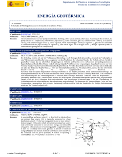
EQUIPEMENT DE CONVERSION D'UN MOUVEMENT DE TRANSLATION ALTERNEE DANS UN FLUIDE EN UN
MOUVEMENT DE ROTATION, ET DISPOSITIF DE RECUPERATION DE L'ENERGIE DES VAGUES METTANT EN OEUVRE
UN TEL EQUIPEMENT.
Nº publicación FR3009032A1 30/01/2015
CENTRE NAT RECH SCIENT¿[FR]
Solicitantes
ECOLE POLYTECH¿[FR]
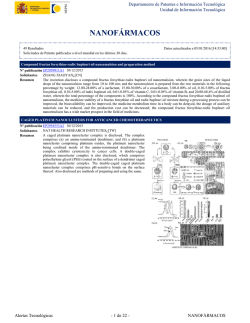
L'invention concerne un équipement de conversion d'un mouvement de translation d'une structure, par rapport à un fluide, en un
Resumen
mouvement de rotation de cette structure, l'équipement comprenant la structure, montée pivotante autour d'un axe (20), et plongée
dans le fluide. Selon l'invention, la structure porte au moins une pale (4, 5) déformable, fixée un point de la structure éloignée de
l'axe (20), la pale (4, 5) présentant au moins une partie flexible de telle sorte que le mouvement de translation de la structure par
rapport au fluide, dans la direction de l'axe, déforme la pale (4, 5) dans une configuration dans laquelle le mouvement de
translation génère une force de poussée sur la pale (4, 5), entrainant la structure en rotation autour dudit axe (20), dans un sens de
rotation identique quand le mouvement de translation est dans un sens ou dans l'autre sens.
L'invention concerne également un équipement de récupération de l'énergie des vagues mettant en ouvre un tel équipement de
conversion de mouvement.
ELECTRICAL GENERATION SYSTEM BASED ON TIDAL FLOW
Nº publicación WO2015013231A2 29/01/2015
TIDAL FAN LLC¿[US]
Solicitantes
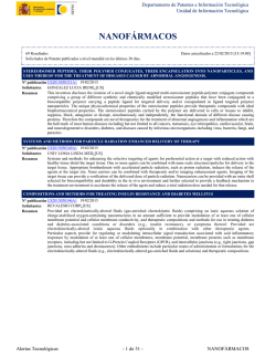
An electrical generation system based on tidal flow includes a
Resumen
reservoir and a fluid inlet tube extending between a tidal source and
the reservoir. The inlet tube has at least one inlet turbine generator
disposed therein. The fluid inlet tube extends along a first level. A
fluid outlet tube extends between the reservoir and the tidal source.
The fluid outlet tube has at least one outlet turbine generator disposed
therein. The fluid outlet tube extends along a second level vertically
lower than the first level. During high tide at the tidal source, tidal
fluid flows from the tidal source, into the fluid inlet tube, past the at
least one inlet turbine generator, and into the reservoir and during a
low tide at the tidal source, the tidal fluid flows from the reservoir,
into the fluid outlet tube, past the at least one outlet turbine generator,
and to the tidal source.
Alertas Tecnológicas
- 1 de 29 -
ENERGÍAS MARINAS
Departamento de Patentes e Información Tecnológica
Unidad de Información Tecnológica
UNDERWATER POWER GENERATOR
Nº publicación US2015028589A1 29/01/2015
ATLANTIS RESOURCES CORP PTE¿[SG]
Solicitantes
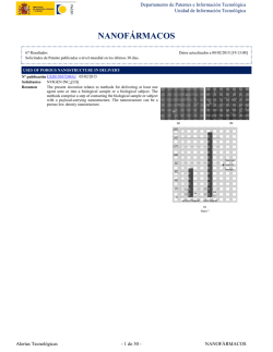
A power generation apparatus for generating power from water flows
Resumen
is described. The power generation apparatus includes: a generator
a first blade set operatively mounted to the generator for rotation in a
selected direction in response to flowing water from a selected
d i r e c t i o n
a second blade set operatively mounted to the generator for rotation
and operatively connected to the first blade set, the second blade set
being disposed coaxially with, and downstream of or in a wake zone
of,
the
first
blade
set
wherein the generator is adapted to be driven by at least one of the
blade sets, the generator being disposed generally coaxially between
the first and second blade sets.
A DEVICE FOR CONVERTING WAVE ENERGY INTO MECHANICAL ENERGY
Nº publicación US2015028595A1 29/01/2015
OXYDICE AS¿[DK]
Solicitantes
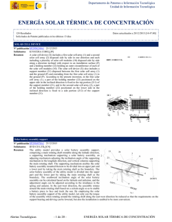
A wave power plant for extracting power from the wave movement of
Resumen
a water surface area, said wave power plant comprising a frame
construction in which at least one rotor is journalled, and wherein the
rotor is suspended in the frame construction on a rotor shaft which is,
in the normal use situation of the wave power plant, essentially
horizontal to the effect that the rotor is able to rotate about the rotor
shaft which is retained in the frame construction, and wherein means
are configured for maintaining each of the rotors partially immersed in
a water surface area. The invention provides increased output
efficiency of such wave power plant by the rotors being mounted on
the rotor shaft via a free-running mechanism which is configured such
that the rotor is able to transfer momentum to the rotor shaft
essentially only when it rotates the one way about the rotor shaft.
Alertas Tecnológicas
- 2 de 29 -
ENERGÍAS MARINAS
Departamento de Patentes e Información Tecnológica
Unidad de Información Tecnológica
Wind force and wave force complementary power supply device
Nº publicación WO2015010440A1 29/01/2015
WENG WEN-KAI¿[CN]
Solicitantes
WENG YUAN-YU¿[CN]
The utility model discloses a wind force and wave force
Resumen
complementary power supply device which comprises a wind force
kinetic energy module, a wave force kinetic energy module and a
mains supply module. The wind force kinetic energy module is
erected on an ocean and rotates a generator by utilizing kinetic energy
generated by wind force to generate power, the wave force kinetic
energy module and the wind force kinetic energy module are erected
on the ocean together and utilizes seawater fluctuation to generate
kinetic energy, and the output end of the wave force kinetic energy
module is in linkage with a transmission shaft to drive the generator to
generate power. The wind force kinetic energy module and the wave
force kinetic energy module generate power respectively to
complement each other to enable the transmission shaft to rotate the
generator continuously and stably to generate power, and the mains
supply module is driven by a servo motor and connected with the
transmission shaft. When the rotating speed of the transmission shaft
is reduced, the servo motor is started to complement and increase the
rotating speed of the transmission shaft to enable the generator to
generate enough electric energy.
CONSTRUCTION METHOD FOR FLOATING WAVE POWER GENERATION COMPLEX THROUGH SHARING OF
MOORING LINE AND FLOATING WAVE POWER GENERATION SYSTEM USING SAME
Nº publicación WO2015012481A1 29/01/2015
KOREA INST OCEAN SCI & TECH¿[KR]
Solicitantes
The present invention relates to the construction of a floating wave power generation complex including a plurality of floating
Resumen
wave power generation devices for wave power generation. According to the present invention, a method for designing a mooring
line for the construction of a floating wave power generation complex and the floating wave power generation system using the
same are provided, wherein it is possible solve the problems of the prior art which had no research on the design of a mooring line
for an energy farm, and a mooring line is shared instead of using an anchor between adjacent floating bodies when connecting the
mooring line for maintaining the positions of each of the floating wave power generation devices such that the length of the
mooring line to be used is reduced and, simultaneously, the use of an anchor is also minimized. Therefore, the costs for a mooring
system which occupies a heavy portion of the entire construction cost can be reduced. In addition, the entire construction cost can
be reduced thereby and, simultaneously, a public water surface area can be reduced.
END SUPPORTED HELICAL TURBINE
Nº publicación WO2015012752A1 29/01/2015
GOX AB¿[SE]
Solicitantes
The claimed invention relates to a turbine adapted to extract energy from the velocity of a streaming fluid such as wind, steam,
Resumen
tidal streams and water waves. The invented turbine is arranged with its axis of turbine rotation directed at substantially right
angles to the current direction of the streaming fluid and comprising a kind of self- supported blade body which is rotationally
symmetric and constructed by rotor blades integrated transversely and supported two by two, allowing the fluid to flow through
the turbine with less turbulence compared to other types of turbines equipped with separate rotor blades.
Alertas Tecnológicas
- 3 de 29 -
ENERGÍAS MARINAS
Departamento de Patentes e Información Tecnológica
Unidad de Información Tecnológica
ELECTRICAL GENERATION SYSTEM BASED ON TIDAL FLOW
Nº publicación WO2015013608A1 29/01/2015
TIDAL FAN LLC¿[US]
Solicitantes
An electrical generation system based on tidal flow includes a
Resumen
reservoir and a fluid inlet tube extending between a tidal source and
the reservoir. The inlet tube has at least one inlet turbine generator
disposed therein. The fluid inlet tube extends along a first level. A
fluid outlet tube extends between the reservoir and the tidal source.
The fluid outlet tube has at least one outlet turbine generator disposed
therein. The fluid outlet tube extends along a second level vertically
lower than the first level. During high tide at the tidal source, tidal
fluid flows from the tidal source, into the fluid inlet tube, past the at
least one inlet turbine generator, and into the reservoir and during a
low tide at the tidal source, the tidal fluid flows from the reservoir,
into the fluid outlet tube, past the at least one outlet turbine generator,
and to the tidal source.
Alertas Tecnológicas
- 4 de 29 -
ENERGÍAS MARINAS
Departamento de Patentes e Información Tecnológica
Unidad de Información Tecnológica
WATER TURBINE
Nº publicación US2015030430A1 29/01/2015
HON CHEE WAH¿[SG]
Solicitantes
DE WIJS BERT¿[SG]
ENGTEK PTE LTD¿[SG]
This invention is relates to water turbine power. In particular, the
Resumen
invention relates to a water turbine for generating power in a body of
water. There is provided a turbine for operation in a body of water for
the generation of power, the turbine comprising: (a) a housing having
an inlet for receiving water and an outlet for allowing water to exit
and (b) a power generation unit disposed in the housing and
intermediate the inlet and outlet, the power generation unit comprising
two propellers for rotation about an axis in response to water flow,
wherein the inlet comprises a flared outer end for channelling the
water towards the power generation unit, and a truncated cone
disposed within the flared outer end of the inlet, the flared portion of
the truncated cone protrudes the inlet.
CN204126812U
Nº publicación CN204126812U 28/01/2015
CN104320045A
Nº publicación CN104320045A 28/01/2015
CN104319973A
Nº publicación CN104319973A 28/01/2015
CN104314743A
Nº publicación CN104314743A 28/01/2015
CN104314741A
Nº publicación CN104314741A 28/01/2015
CN104314740A
Nº publicación CN104314740A 28/01/2015
CN104314739A
Nº publicación CN104314739A 28/01/2015
CN104314738A
Nº publicación CN104314738A 28/01/2015
CN104314737A
Nº publicación CN104314737A 28/01/2015
Alertas Tecnológicas
- 5 de 29 -
ENERGÍAS MARINAS
Departamento de Patentes e Información Tecnológica
Unidad de Información Tecnológica
CN104314736A
Nº publicación CN104314736A 28/01/2015
CN104314735A
Nº publicación CN104314735A 28/01/2015
CN204126839U
Nº publicación CN204126839U 28/01/2015
CN204131363U
Nº publicación CN204131363U 28/01/2015
SYSTEM AND METHOD FOR CONVERTING FLUID MOTION INTO ELECTRICAL POWER
Nº publicación CN104321526A 28/01/2015
A system is provided for converting fluid motion into electrical
Resumen
power, with the system being deployable in a body of fluid. The
system includes a support structure (106) and a movable structure
(108, 300, 400) connected to the support structure (106). The support
structure (106) includes a generator assembly (120, 200) configured to
convert mechanical energy to electrical energy and provide electric
power from the electrical energy. The movable structure (108, 300,
400) has three or more degrees of freedom, and is configured to
generate mechanical energy for conversion by the generator assembly
(120, 200) during a power generation phase of a power cycle in which
the
fluid
motion
acts
on
the
movable
structure
(108,
300,
400).
The movable structure (108, 300, 400) has a first configuration during the power generation phase and a second, different
configuration during a recovery phase of the power cycle, with the movable structure (108, 300, 400) in the first configuration
having a greater surface area normal to the flow of fluid.
CN104314734A
Nº publicación CN104314734A 28/01/2015
CN204126808U
Nº publicación CN204126808U 28/01/2015
CN204126809U
Nº publicación CN204126809U 28/01/2015
CN204126810U
Nº publicación CN204126810U 28/01/2015
CN204126811U
Nº publicación CN204126811U 28/01/2015
Procedimiento de generación de agua potable y energía eléctrica mareomotriz
Nº publicación ES2527699A1 28/01/2015
ECOSIST S DE AHORRO S L¿[ES]
Solicitantes
JIMENEZ LAVILLA ANGEL¿[ES]
LEIRA MARTINEZ JOSÉ ANTONIO¿[ES]
IGLESIAS BARTOLOME JAIME¿[ES]
Alertas Tecnológicas
- 6 de 29 -
ENERGÍAS MARINAS
Departamento de Patentes e Información Tecnológica
Unidad de Información Tecnológica
METHOD FOR PRODUCING A CIRCUIT BOARD AND USE OF SUCH A METHOD
Nº publicación CN104322157A 28/01/2015
The invention relates to a method for producing a circuit board
Resumen
comprising the following steps: - providing at least one first element
of the circuit board to be produced, more particularly a multilayer core
e l e m e n t
( 3 1 )
- applying an adhesion-preventing material (39) to a region of the first
element
(31)
to
be
subsequently
exposed
- applying at least one additional layer (40, 41) to the first element
(
3
1
)
- connecting the first element (31) and the at least one additional layer
( 4 0 ,
4 1 )
and - removing a portion (44, 45) of the additional layer to expose the
region of the first element, wherein in the additional layer
corresponding to the portion to be subsequently removed, the material
of the additional layer (40, 41) is cut through on at least one edge of
the portion (44, 45) to be subsequently removed and the cut-through
area (46, 47) is optionally filled with a different material from the
material of the additional layer, before an application onto the first
element (31) and/or a connection thereto is performed, so as to
subsequently enable easy removal of the portion (44, 45) to be
removed.
HYDROELECTRIC GENERATOR
Nº publicación US2015021920A1 22/01/2015
NOGUEIRA DIAS DA SILVA HERNANI JOSE¿[PT]
Solicitantes
The present invention essentially consists of a turbine that has rotary
Resumen
concave blades (11) and can be mounted in the stream of a river bed
for producing energy. The system can comprise maximum six
hexagonal helices, which is the most suitable shape for better
capturing the force of the current of the river stream, such that the
movement of the helix does not hinder turbine rotation, increasing on
the contrary the speed of rotation when immersed into or emerging
from the water. The helices are mounted on a rotation shaft having at
the ends thereof a male pinion (12) that is connected to a female
pinion (13) arranged inside a speed reduction gearbox. Multiple
turbines can be provided, depending on the motive force of each water
stream, and can be connected to two current generators arranged one
on each side, ensuring that the force impinging on the turbine is
regular and balanced.
Alertas Tecnológicas
- 7 de 29 -
ENERGÍAS MARINAS
Departamento de Patentes e Información Tecnológica
Unidad de Información Tecnológica
Multi-Megawatt Ocean Current Energy Extraction Device
Nº publicación US2015021919A1 22/01/2015
AQUANTIS INC¿[US]
Solicitantes
An underwater apparatus for generating electric power from ocean
Resumen
currents and deep water tides. A submersible platform including two
or more power pods, each having a rotor with fixed-pitch blades, with
drivetrains housed in pressure vessels that are connected by a
transverse structure providing buoyancy, which can be a wing
depressor, hydrofoil, truss, or faired tube. The platform is connected to
anchors on the seafloor by forward mooring lines and a vertical
mooring line that restricts the depth of the device in the water column.
The platform operates using passive, rather than active, depth control.
The wing depressor, along with rotor drag loads, ensures the platform
seeks the desired operational current velocity. The rotors are directly
coupled to a hydraulic pump that drives at least one constant-speed
hydraulic-motor generator set and enables hydraulic braking.
A fluidic bearing decouples non-torque rotor loads to the main shaft
driving the hydraulic pumps.
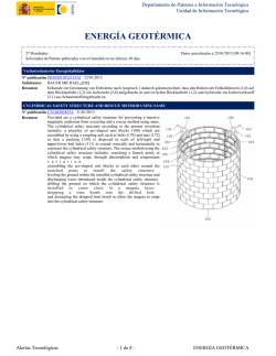
DEVICE FOR CONVERSION OF MECHANICAL ENERGY FROM SEA WAVES TO ELECTRIC ENERGY
Nº publicación US2015021918A1 22/01/2015
ENSEA S R L¿[IT]
Solicitantes
Device (100) for conversion of mechanical energy from sea waves to
Resumen
electric energy, characterized by: - at least a float (101) and two rigid
rods (102), (103), preferably anchored at one end to the seabed (108),
and at the other end to the float (101) through flexible cables (106),
( 1 0 7 )
two respective masses (104), (105) keep the free ends of that rods
(102), (103), constantly in traction condition pulled towards the sea
b e d
( 1 0 8 )
- at least a power generator (109), or other similar device suitable to
convert and/or transmit energy, that is placed close to its respective
hinge (110), (111), placed at the bottom parts of the rods (102), (103),
so that the oscillatory motion of the float (101), following the waves
level (112), causes a force with a vertical component that leads to a
rotatory and oscillatory motion of the rods (102), (103), which are
pivoted on its respective hinge (110), (111), and generates therefore
electric energy by motion of gears of the same generator (109)
the horizontal component of the force due to the float (101)
oscillations is balanced by a system of counterweights, so that the
same float (101) tends to place itself constantly on vertical line A-A'.
Alertas Tecnológicas
- 8 de 29 -
ENERGÍAS MARINAS
Departamento de Patentes e Información Tecnológica
Unidad de Información Tecnológica
VERTICAL AXIS WIND AND HYDRAULIC TURBINE WITH FLOW CONTROL
Nº publicación AU2013291592A1 22/01/2015
RUBIO ANA
Solicitantes
RUBIO HUMBERTO
A vertical axis wind and hydraulic turbine with flow control
Resumen
comprising a regular hexagonal structure of radius R,
parallelepiped-shaped, inside which a rotor rotates with three or more
vanes on a vertical axis which is located in the center of the hexagon
as seen from above, wherein said vanes when rotating generate a
circle of radius Rt, further comprising six articulated deflector vanes
that grab and concentrate the flow of air or liquid entering the rotor
vanes, from the wind or liquid current entry side to the turbine and
diffuse the flow of air or liquid exiting from the rotor vanes, from the
side opposite to the wind or liquid entry side to the turbine.
MODULAR SAND FILTRATION-ANCHOR SYSTEM
Nº publicación AU2013286961A1 22/01/2015
MURTECH INC
Solicitantes
A filter-anchor is provided, including a filter housing for filtering sea
Resumen
water prior to entry into a water desalination system for placement on
a sea floor, the filter housing having an exterior, an interior chamber,
at least one inlet for providing the sea water to the interior chamber,
and at least one outlet for providing filtered water to exit the interior
chamber. A sand filter disposed is in the filter-housing, separating the
exterior from the interior chamber, the filter housing having at least
one water conduction outlet conduit for filtered water to exit the
interior chamber to provide filtered water. A wave energy conversion
system utilizing the filter anchor is also provided. A method of
anchoring a wave energy conversion system and providing filtered
water to a desalination system is also provided.
Alertas Tecnológicas
- 9 de 29 -
ENERGÍAS MARINAS
Departamento de Patentes e Información Tecnológica
Unidad de Información Tecnológica
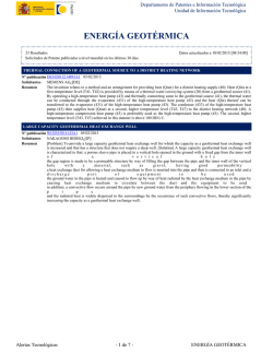
Turbine with venturi pump augmented flow
Nº publicación AU2013279111A1 22/01/2015
VERDERG LTD
Solicitantes
An apparatus for generating electricity from water flow 32, 34
Resumen
comprises a convergent section 14, a diffuser section 20 and tube 22
housing a turbine 26 located at least partly within the convergent
section 14. The convergent section is connected to a first end of a
mixing chamber 16 such that a venturi 18 is defined between the end
of the convergent section 14 and the mixing chamber 16. The diffuser
section 20 is connected to a second end of the mixing section 16. An
annulus is defined between the tube 22 and the convergent section 14,
to form a first flow passage. Flow 32 through the venturi reduces
pressure and so induces greater flow through the tube 22, allowing a
smaller turbine 26 to be used to generate a given amount of power.
The apparatus may be located with a barrier or dam (figure 1) to
increase static head.
WAVE POWER GENERATION SYSTEM AND METHOD
Nº publicación AU2013271344A1 22/01/2015
DDNT CONSULTANTS AUSTRALIA PTY LTD
Solicitantes
A power generator comprises a casing (110) that in use is deployed in
Resumen
an environment in which the casing is subjected to an excitation
motion such as wave motion. A series of masses (101, 103a-c) is
located within the casing, wherein at least a first mass is coupled to
the casing by a first spring (102), each of the masses is coupled to at
least one adjacent mass by a respective spring, and wherein the casing
and the series of masses bring a motion of the power generator into
resonance with the excitation motion. A plurality of electric machines
each comprising a stator and a field source are each associated with a
corresponding mass such that a relative motion of a mass and
associated electric machine generates electrical power. A power
takeoff circuit receives generated electrical power from the plurality
of electric machines and outputs electrical power from the power
generator.
Alertas Tecnológicas
- 10 de 29 -
ENERGÍAS MARINAS
Departamento de Patentes e Información Tecnológica
Unidad de Información Tecnológica
APPARATUS FOR GENERATING ENERGY
Nº publicación AU2013255987A1 22/01/2015
FRIEDENTHAL REGINALD
Solicitantes
Apparatus for generating energy in which an oscillating air column
Resumen
created by wave motion continuously drives a turbine in one direction.
SYSTEM FOR GENERATING ELECTRICAL ENERGY, BASED ON AN ARTIFICIAL REEF
Nº publicación WO2015009134A1 22/01/2015
ZALDÍVAR VELÁZQUES CARLOS EDUARDO¿[MX]
Solicitantes
Pure wave energy or energy converted into kinetic energy in the form of a wave on the coast is received by an artificial reef
Resumen
which has a ramp, on the upper part thereof, suitably designed to raise the maximum volume of sea water to the maximum
possible height, depositing it in the channel of the reef as potential energy or altitude energy, and flows through a horizontal
channel to land area. Once it arrives at the weir, it falls on the rotor of a generator, producing electricity which is sent to the
distribution network. The sea water returns in the form of a river and/or filters through the marine farm, providing said farm with
calm, oxygenated water which is safe to be used as a hatchery for breeding sea species.
Alertas Tecnológicas
- 11 de 29 -
ENERGÍAS MARINAS
Departamento de Patentes e Información Tecnológica
Unidad de Información Tecnológica
WAVE POWER GENERATION APPARATUS
Nº publicación WO2015008891A1 22/01/2015
LIM CHE KYUNG¿[KR]
Solicitantes
The present invention is capable of transmitting the continuous
Resumen
driving force without a break even if the wave power is not
transmitted as pendulum movement is performed by the wave power
progressed in both directions on the water surface and pendulum
movement force is delivered to a generator by converting into the
continuous rotational force with a plurality of weights. The wave
power generator according to the present invention comprises: a frame
formed in a wedge structure in order for the lower end to be supported
on an ocean floor and in which the upper end is protruding from a sea
l e v e l
a main body arranged on the upper part of the frame
a floating body in which pendulum movement is performed around
pivot by wave energy delivered from the progressing wave delivered
in both direction of one side and the other side as being constrained on
one side of the main body and the lower part is arranged on the sea
l e v e l
a movement force converting unit formed on the upper part of the
main body, connected to be interlocked with a connection board
connected to be flexible in a longitudinal direction on the upper part of
the floating body so that the pendulum movement of the floating body
is
converted
into
the
rotational
force
a gear box built in the main body and for converting the rotational
force of the movement force converting unit into the continuous
rotational force in a one-way clutch method with the weight
and a driving force transmission member for transmitting the output of
the gear box to the generator.
Power Generating Hydroconveyor
Nº publicación US2015021921A1 22/01/2015
CUNNANE FRANK PATRICK¿[US]
Solicitantes
Hydroconveyors are described which utilize magnetic levitation or
Resumen
magnetic suspension to support a collection of conveyor elements.
The hydroconveyors are located above or partially within a
flowstream such as a river. Additional versions of the hydroconveyors
are described which include velocity increasing waterways located
upstream of an end of the hydroconveyor. The various
hydroconveyors can be used in conjunction with electrical generators
to provide electrical power.
CN204119003U
Nº publicación CN204119003U 21/01/2015
Alertas Tecnológicas
- 12 de 29 -
ENERGÍAS MARINAS
Departamento de Patentes e Información Tecnológica
Unidad de Información Tecnológica
SYSTEM FOR GENERATING ELECTRICITY BY MEANS OF NATURAL-ELEMENT PRESSURE
Nº publicación EP2826990A1 21/01/2015
CAMPILLO FERRE JOAN¿[ES]
Solicitantes
The subject matter of the present invention is a system for generating
Resumen
electricity by means of natural-element pressure, which is set up, in
terms of the basic use thereof, to utilize the hydraulic pressure in a
channel (1) of flowing water (2) with preferably sloping lateral zones
(3), comprising platforms (4) and turbines (5) supported on shafts (6)
and (7) located transversely over the channel (1). The platform (4) has
a first, straight portion (41) over the flowing water (2) and a second,
submerged portion (42) with a curvature (43) below which is the
turbine (5) and ending with a final straight portion. The shafts (6) and
(7) of platforms (4) and turbines (5) are fixed in supporting ends (11)
and (8) anchored at the sides (3) of the channel (1), linking the shaft
(7) of the turbine to an alternator (9) connected to the grid (10).
Upstream of the platforms are gates (12) in the form of a funnel that
reduce the amount of water (2) passing through.
CN204113530U
Nº publicación CN204113530U 21/01/2015
CN204113529U
Nº publicación CN204113529U 21/01/2015
CN204113528U
Nº publicación CN204113528U 21/01/2015
CN204113527U
Nº publicación CN204113527U 21/01/2015
CN204113526U
Nº publicación CN204113526U 21/01/2015
CN204113525U
Nº publicación CN204113525U 21/01/2015
CN204113523U
Nº publicación CN204113523U 21/01/2015
CN204113522U
Nº publicación CN204113522U 21/01/2015
CN204113521U
Nº publicación CN204113521U 21/01/2015
CN204113520U
Nº publicación CN204113520U 21/01/2015
CN104295434A
Nº publicación CN104295434A 21/01/2015
CN104295433A
Nº publicación CN104295433A 21/01/2015
Alertas Tecnológicas
- 13 de 29 -
ENERGÍAS MARINAS
Departamento de Patentes e Información Tecnológica
Unidad de Información Tecnológica
SMALL HYDROELECTRIC GENERATOR USING SEWAGE
Nº publicación CN104295430A 21/01/2015
The present invention relates to a small hydroelectric generator using
Resumen
sewage, which is installed between the end hole of a sewer pipe and
an intercepting pipe, and able to produce electricity by using sewage
flowing from the end hole of the sewer pipe. The small hydroelectric
generator using sewage of the present invention in order to solve the
problem is installed between the end hole of a sewer pipe and an
intercepting pipe, and comprises a rainwater/wastewater pipe part
fixed to the end hole of the sewer pipe on one end
a turbine room having a water wheel generater inside, a top through
which the other end of the rainwater/wastewater pipe part penetrates,
and a bottom with a drainpipe connected to the intercepting pipe
a power transfer unit including a shaft in gear with a rotary shaft of the
water
wheel
generator
and a generating room having a generator in gear with the shaft,
wherein the water wheel generator is arranged on the outlet portion of
the rainwater/wastewater pipe part, and the rotary shaft is vertically
installed.
CN204113531U
Nº publicación CN204113531U 21/01/2015
¿¿¿¿¿¿¿¿¿¿¿¿¿
Nº publicación JP2015010599A 19/01/2015
(¿¿)¿¿¿¿¿¿¿¿¿¿¿¿¿¿¿¿¿¿¿¿¿¿¿¿¿¿¿¿¿¿¿¿¿¿¿¿,¿¿¿¿¿¿¿¿¿¿¿¿¿¿¿¿¿¿¿¿¿¿¿¿¿¿¿¿.(¿¿¿¿)¿¿¿¿¿¿¿¿¿¿¿¿¿¿,¿¿¿¿¿¿¿¿¿¿¿¿¿¿¿¿¿,¿¿¿¿¿¿¿¿w¿¿
Resumen
¿¿¿¿¿¿¿¿¿¿¿¿¿¿¿¿¿¿¿¿¿¿¿¿¿¿¿¿¿¿¿¿,¿¿¿¿¿¿¿¿¿¿¿¿¿¿¿¿¿¿¿¿¿¿¿¿¿¿¿¿¿¿,¿¿¿¿¿¿¿¿¿¿¿¿¿,¿¿¿¿¿¿¿¿¿¿¿¿¿¿¿w¿¿¿¿¿¿¿¿¿¿¿¿¿¿¿¿¿¿¿¿¿
¿,w¿¿¿¿¿¿¿¿¿¿¿¿¿¿¿¿¿¿¿¿¿¿¿¿¿,¿¿¿¿¿¿¿¿¿¿¿¿¿¿¿¿¿¿¿¿¿¿¿¿¿¿¿¿¿¿¿¿¿¿¿¿¿¿¿¿¿¿¿.(¿¿¿)¿1
A TURBINE AND A ROTOR FOR A TURBINE
Nº publicación HK1156676A1 16/01/2015
BRI TOINNE TEORANTA¿[IE]
Solicitantes
Alertas Tecnológicas
- 14 de 29 -
ENERGÍAS MARINAS
Departamento de Patentes e Información Tecnológica
Unidad de Información Tecnológica
ENERGY PLANT AND PARTS OF AN ENERGY PLANT
Nº publicación US2015014996A1 15/01/2015
SILTALA TIMO¿[FI]
Solicitantes
SUBSEA ENERGY OY¿[FI]
The invention pertains to underwater energy plants utilizing water
Resumen
movement due to e.g. waves, tide or stream. The invention also relates
to parts of such a plant, namely an underwater wing (9, 10, 11) for
capturing wave energy, apparatus (12) to convert the mechanical
energy to electrical energy, and a connector (46) for transferring the
electrical energy. In certain embodiments of the invention, a wing (9,
10, 11) causes a moment around hinging axis due to water flow with
autonomous or tethered in-hinge electric generator and underwater
attachable high power electric connector (46) based on inductive
transfer of energy.
MARINE POWER GENERATING SYSTEM AND MARINE POWER GENERATING METHOD
Nº publicación US2015014995A1 15/01/2015
NISHIOKA TOSHIHISA¿[JP]
Solicitantes
[Problem] To provide a marine power generating system which is
Resumen
engineered to be able carry out power generation stably and highly
efficiently, using the large source of energy even in ocean currents
having insufficient speeds to create a water current, similar to a water
discharge from a dam, which is ideal for hydroelectricity. [Solution]
As an example of a water intake structure (10), a sea surface floatation
object floats on the sea by buoyancy, and has an aperture part (12)
through which seawater is taken therein. A water guide pipe (20) is
underwater, which secures a space underwater. One end of the water
guide pipe (20) is connected to the sea surface floatation object (10),
and the seawater which is taken in from the sea surface floatation
object which is the water intake structure (10), is introduced
downward under the sea surface. Power generators (30) which
generate power from either the falling motion of the seawater or water
pressure are in the water guide pipe (20), and carry out power
generation. A submersible body (40) is in the water, and an
accumulation space (41) is provided which takes in the seawater
which is discharged from another end of the water guide pipe (20).
The seawater which is taken into the accumulation space (41) in the
submersible body (40) is discharged outward from the submersible
body (40) by a discharge part (50).
Alertas Tecnológicas
- 15 de 29 -
ENERGÍAS MARINAS
Departamento de Patentes e Información Tecnológica
Unidad de Información Tecnológica
HYDROELECTRIC POWER SYSTEM AND PUMP
Nº publicación US2015013327A1 15/01/2015
BATEHAM LAIRD GALEN¿[CA]
Solicitantes
A hydroelectric power system and pump suitable for the system are
Resumen
disclosed which can make efficient use of the energy available in
water flows with considerably variable flow rates. A simple, compact
variable displacement axial piston pump can be operated so as to
provide an essentially constant output pumping pressure and variable
output volume that varies efficiently in accordance with water flow
rate. The system is particularly suitable for shoreline tidal power
generation and provides firm power output throughout the tidal slacks
occurring during the tidal reversals.
WAVE ENERGY CONVERTER SYSTEM
Nº publicación US2015013325A1 15/01/2015
DEHLSEN ASSOCIATES LLC¿[US]
Solicitantes
The invention is a wave energy device which optimizes energy
Resumen
conversion from waves with a stable submerged platform coupled to
compliant chain of floats ("pods") which are connected to the platform
by piston pumps. Wave action drives pumps to deliver pressurized
water to a hydro turbine coupled to an electric generator for delivery
of electric power to shore via a submarine cable. Alternatively, the
pressurized water may be delivered to shore through pipes on the
ocean floor, to generate electric power, also as input flow for reverse
osmosis potable water production and for cooling applications.
Alertas Tecnológicas
- 16 de 29 -
ENERGÍAS MARINAS
Departamento de Patentes e Información Tecnológica
Unidad de Información Tecnológica
DEVICE FOR CONVERTING SWELL MOVEMENT INTO ENERGY
Nº publicación WO2015004333A1 15/01/2015
SA2P¿[FR]
Solicitantes
The invention relates to a device for converting swell movement into energy, which comprises at least one arm (1) supporting a
Resumen
float and swinging about a horizontal axis (20) when the swell moves, and a reverser mechanism (3) including a main gear (4) for
rotating an output shaft and onto which, in two diametrically opposed areas, a pair of conical gears (5, 5') mesh that can be
rotatably secured to said arm (1) in two opposite directions, respectively. According to the invention, the device includes at least
three arms (1) which each support a float and extend radially along at least three directions (10) distributed about the central
vertical axis (30) of the carrier (M), in the shape of a star, wherein said arms (1) are swingably mounted, respectively, about
concurrent hinge axes (20) extending through said central axis (30), and the reverser mechanism (3) includes a single main wheel
(4) for rotating the output shaft and, for each arm (1), a pair of opposite conical gears (5, 5') each rotatably secured in one
direction with said arm (1). The device according to the invention is particularly intended for recovering swell energy for power
generation, fluid pumping or gas compression.
SEA WAVE GENERATOR WITH WATER-AIR COMPRESSION
Nº publicación WO2015005879A1 15/01/2015
OZDEMIR BERTAN¿[TR]
Solicitantes
The present invention is related to a wave generator which transfers the kinetic energy and lifting force of sea waves by
Resumen
compressing sea water and air, which stores said compressed sea water and air in closed containers and when necessary, produces
electric from said compressed air. The invention basically comprises a cylinder (1) submerged into the sea, a piston (2) which
moves forwards and backwards inside the cylinder, at least one, preferably cylindrical barge (3) which floats on the sea surface, a
rope-roller system (4,5) which transfers the motion of the barge (3) to the piston, a storage tank (6) comprising air and water, a
connection pipe (7) which connects the tank (6) to the cylinder (1), at least a small barge (8) submerged into the sea, which is
connected to the cylindrical barge (3) via a rope (Figure-1).
ANCHORABLE WAVE ENERGY CONVERTOR
Nº publicación WO2015003229A1 15/01/2015
LAMINARIA BVBA¿[BE]
Solicitantes
Anchorable wave energy convertor with a floating main body (110), at least two anchor lines (121, 122) and energy conversion
Resumen
means, wherein the at least one anchor line is adapted to be anchored to the bottom (20) of a body of water (10) at least at two
distinct points, wherein the main body is connected to the at least two anchor lines via rotation means (133), such that a horizontal
first movement of the main body with respect to the two points results in a second movement of the rotation means (133), and
wherein the conversion means are adapted to convert the second movement in another form of energy. The wave energy
convertor further comprising coiling means (140) for controlling the vertical position of the main body, wherein the coiling means
are formed as a differential.
UNDERWATER POWER STATION
Nº publicación WO2015003963A1 15/01/2015
VOITH PATENT GMBH¿[DE]
Solicitantes
An underwater power station having a generator which has a stator and a rotor, wherein water is located in a gap between the
Resumen
stator and the rotor and water flows around the encapsulated stator, the generator being a reluctance machine.
UNDERWATER POWER STATION
Nº publicación DE102013213479A1 15/01/2015
VOITH PATENT GMBH¿[DE]
Solicitantes
An underwater power station having a generator which has a stator and a rotor, wherein water is located in a gap between the
Resumen
stator and the rotor and water flows around the encapsulated stator, the generator being a reluctance machine.
CN204099118U
Nº publicación CN204099118U 14/01/2015
CN204099117U
Nº publicación CN204099117U 14/01/2015
CN204099116U
Nº publicación CN204099116U 14/01/2015
CN204099115U
Nº publicación CN204099115U 14/01/2015
Alertas Tecnológicas
- 17 de 29 -
ENERGÍAS MARINAS
Departamento de Patentes e Información Tecnológica
Unidad de Información Tecnológica
CROSS FLOW TURBINE WITH STRAIGHT VERTICAL AND HELICAL SLANTED BLADES
Nº publicación EP2823181A1 14/01/2015
AXIS ENERGY GROUP PTY LTD¿[AU]
Solicitantes
A structural duct apparatus includes a cross flow turbine for use in a
Resumen
fluid flow. The turbine has at least one straight vertical aerofoil blade
and at least one helical aerofoil blade slanted toward the direction of
rotation. Inner and outer walls of the duct apparatus provide an inner
diffuser flow passageway that houses turbine power take off modules
with the outer surfaces of the duct influencing flow direction so that
where there are at least two ducts an open flow barrage is
advantageously formed.
CN204099113U
Nº publicación CN204099113U 14/01/2015
CN204099112U
Nº publicación CN204099112U 14/01/2015
CN104278662A
Nº publicación CN104278662A 14/01/2015
CN104273064A
Nº publicación CN104273064A 14/01/2015
CN204099114U
Nº publicación CN204099114U 14/01/2015
Alertas Tecnológicas
- 18 de 29 -
ENERGÍAS MARINAS
Departamento de Patentes e Información Tecnológica
Unidad de Información Tecnológica
WAVE/TIDAL & WIND ENERGY CONVERTERS
Nº publicación DK201300188A1 12/01/2015
PEDERSEN MOGENS MÖLHEDE¿[DK]
Solicitantes
LOVING MICHAEL MÖLHEDE¿[DK]
DAMKIER CHRISTINA MÖLHEDE¿[DK]
The invention relates to an energy installation comprising one or more
Resumen
aerofoil profiles having a longitudinal axis oriented vertically, said
profile being configured on a rotatable lever arm, a support structure
comprising a transmission system where said vertical profile (1A)
may rotate around its longitudinal axis and in that said lever arm (2)
and said vertical profile (1A) may oscillate between a first and a
second horizontal positions by means of a flow of particles acting on
said vertical profile (1A) such that a horizontal movement of said
vertical profile (1A) is achieved and transmitted to said transmission
system via said lever arm (2).
¿¿¿¿¿¿¿¿¿¿¿¿¿¿¿¿
Nº publicación JP3195135U 08/01/2015
(¿¿)¿¿¿¿¿¿¿,¿¿¿¿¿¿¿¿¿,¿¿¿¿¿¿¿¿¿¿¿¿¿¿¿¿¿¿¿¿¿¿¿¿¿¿¿¿¿¿.(¿¿¿¿)¿¿¿¿¿¿¿¿(¿¿)¿¿¿¿¿¿¿¿¿¿¿¿¿¿¿¿¿¿¿¿¿¿¿¿¿¿¿¿¿,¿¿¿¿¿¿¿12¿¿¿¿¿¿¿¿¿¿¿1¿
Resumen
¿¿¿¿17¿¿¿¿¿¿,¿¿¿¿¿¿¿¿¿¿¿¿¿¿¿¿¿¿¿¿,¿¿¿¿¿¿¿¿17¿¿¿¿¿¿¿¿¿¿¿¿¿¿¿¿¿¿¿¿¿¿¿¿¿¿¿2¿¿¿¿¿¿¿¿¿¿¿¿¿¿¿¿¿¿¿¿¿¿¿¿¿¿¿¿¿¿¿¿¿¿¿¿¿¿¿¿¿¿¿¿¿¿
¿¿¿.(¿¿¿)¿3
Alertas Tecnológicas
- 19 de 29 -
ENERGÍAS MARINAS
Departamento de Patentes e Información Tecnológica
Unidad de Información Tecnológica
Releasable infrastructure module for underwater power installation
Nº publicación JP2015500952A 08/01/2015
An infrastructure arrangement 5 for use in an underwater power
Resumen
generation installation includes a support structure for engagement
with the bed 3 of a body of water, and an infrastructure module which
houses infrastructure equipment such as monitoring, switching or
control equipment, or transformers for connection to power generating
units of the installation. The infrastructure module is releasably
engaged with the support structure, so that it can be recovered to the
surface for maintenance. The connection between the infrastructure
module and the support may allow connection in any angular
orientation, and the connectors may be able to be rotated to allow
alignment. There may be a connector part on either the module or the
support that is axially moved into engagement with the mating part.
Releasable water turbine mount with electrical connector
Nº publicación JP2015500951A 08/01/2015
An underwater structure 1 comprises a power generation unit such as
Resumen
a turbine 4, attached to a support structure 2 via a mounting portion
31. The mounting portion connects to the support by continuous
support surfaces e.g. annular flanges 32, 51, which can engage in any
relative rotational position, thereby reducing the need for accurate
alignment during installation. An actuator 39 moves electrical
connectors 57 in rotation to the correct alignment, and linearly to
make up the connection. One of the connectors may be provided with
positional float, e.g. through flexible mountings (figures 9-14) to
allow for any misalignment due to manufacturing and assembly
tolerances. The electrical connector 57 of the support part may be
removable by locking actuators 53, 54 e.g. to allow for maintenance
without requiring underwater cutting and welding.
Alertas Tecnológicas
- 20 de 29 -
ENERGÍAS MARINAS
Departamento de Patentes e Información Tecnológica
Unidad de Información Tecnológica
Multifunctional carrying device for tidal generator and using method of multifunctional carrying device
Nº publicación WO2015000366A1 08/01/2015
ZHANG CHANG¿[CN]
Solicitantes
The invention provides a multifunctional carrying device for tidal
Resumen
generators and a using method of the multifunctional carrying device.
The multifunctional carrying device for the tidal generator comprises
a long main floating body, carrying frames, a remote air pipe and
automatic depth fixing and stabilizing parts, wherein the carrying
frames which horizontally extend towards the left side and the right
side from the middle part of the long main floating body and the end
parts of the carrying frames are used for carrying the tidal generators
the long main floating body is a central floating control pipe with two
closed ends, cable tying positions are arranged at the two ends of the
central floating control pipe, a pipe air inlet/outlet is arranged above
one end of the central floating control pipe and a pipe water
inlet/outlet is arranged below the other end of the central floating
c o n t r o l
p i p e
one end of the remote air pipe is connected with the pipe air
inlet/outlet and the other end of the remote air pipe is connected with a
control
switch
the central floating control pipe is connected with the carrying frames
through
orthogonal
node
components
and the automatic depth fixing and stabilizing parts are evenly
arranged on rigid parts which are directly connected with the
orthogonal node components along the vertical bisection plane of the
orthogonal node components. The multifunctional carrying device has
a high-efficiency floating and sinking control function and an
automatic depth fixing and stabilizing function.
Alertas Tecnológicas
- 21 de 29 -
ENERGÍAS MARINAS
Departamento de Patentes e Información Tecnológica
Unidad de Información Tecnológica
A wave energy converter
Nº publicación WO2015001115A1 08/01/2015
DICK WILLIAM¿[IE]
Solicitantes
A wave energy converter 100 comprises a heaving buoy 120 coupled
Resumen
to an adjustable reference mass 125 comprising a volume for
accommodating sea water. The heaving buoy 120 and the adjustable
reference mass 125 move together in response to passing waves. A
chamber 105 within the heaving buoy is in fluid communication with
the sea for trapping a volume of air above an enclosed column of
water. The height of the enclosed column of water varies as the point
absorber 122 reacts against its surface via an adjustable air-spring. A
power take off turbine is driven by a stream of vented air from the
chamber 105 as the point absorber reacts against the trapped volume
of air. The reference mass is adjustable by opening valves 150 at
either end of vertically orientated cylinders 146 to trap sea water. The
resistance of the turbines may be varied e.g. using switched reluctance
generators.
Alertas Tecnológicas
- 22 de 29 -
ENERGÍAS MARINAS
Departamento de Patentes e Información Tecnológica
Unidad de Información Tecnológica
MARINE TURBINE COMPRISING A STATOR, A ROTOR, A FIRST MAGNETIC BEARING SUPPORTING THE ROTOR AND
A SECOND SUPPORT BEARING WITH ROLLING ELEMENT(S)
Nº publicación US2015008676A1 08/01/2015
GE ENERGY POWER CONVERSION TECHNOLOGY LTD¿[GB]
Solicitantes
This marine turbine comprises a stator (12), a rotor (14), the rotor (14)
Resumen
being able to be driven in rotation about an axis of rotation (X) by a
stream of a liquid, and at least one first bearing (20A, 20B) for
supporting the rotor (14), the or each first bearing (20A, 20B,
comprising a magnetic stator element (46A, 46B) secured to the stator
(12) and a magnetic rotor element (48A, 48B) secured to the rotor
(14). The marine turbine further comprises at least one second bearing
(22A, 22B) for supporting the rotor (14), the or each second bearing
(22A, 22B) comprising at least one rolling element (50).
METHOD FOR PRODUCING A CIRCUIT BOARD AND USE OF SUCH A METHOD
Nº publicación US2015007934A1 08/01/2015
AUSTRIA TECH & SYSTEM TECH¿[AT]
Solicitantes
The invention relates to a method for producing a circuit board
Resumen
comprising the following steps: - providing at least one first element
of the circuit board to be produced, more particularly a multilayer core
e l e m e n t
( 3 1 )
- applying an adhesion-preventing material (39) to a region of the first
element
(31)
to
be
subsequently
exposed
- applying at least one additional layer (40, 41) to the first element
(
3
1
)
- connecting the first element (31) and the at least one additional layer
( 4 0 ,
4 1 )
and - removing a portion (44, 45) of the additional layer to expose the
region of the first element, wherein in the additional layer
corresponding to the portion to be subsequently removed, the material
of the additional layer (40, 41) is cut through on at least one edge of
the portion (44, 45) to be subsequently removed and the cut-through
area (46, 47) is optionally filled with a different material from the
material of the additional layer, before an application onto the first
element (31) and/or a connection thereto is performed, so as to
subsequently enable easy removal of the portion (44, 45) to be
removed.
Alertas Tecnológicas
- 23 de 29 -
ENERGÍAS MARINAS
Departamento de Patentes e Información Tecnológica
Unidad de Información Tecnológica
HYBRID DEVICE FOR PRODUCING POWER
Nº publicación WO2015001229A1 08/01/2015
GEPS INNOV¿[FR]
Solicitantes
The invention relates to a device which includes: a marine current
Resumen
turbine (14) and/or a wind turbine (8) and/or coupling means for
electromagnetically, electrically or mechanically coupling the marine
current turbine and/or the wind turbine to at least one pump, and a
wave-energy device (5) including: a receptacle which oscillates, when
exposed to said movements, about a vertical shaft, which includes at
least one peripheral compartment located around a central
compartment, placed in fluid communication with same and which the
pump supplies with liquid taken from elsewhere, and which contains
said liquid which, with the oscillations of the receptacle, flows via the
central
compartment
and at least one first turbine arranged in the central compartment and
coupled with an alternator connected to an electric power supply line
of a facility that is external to the device and located remotely.
A WAVE ENERGY EXTRACTION DEVICE
Nº publicación WO2015001284A1 08/01/2015
ADKINS NICHOLAS JAMES¿[GB]
Solicitantes
A wave energy extraction device comprises a hull and at least one driving mass, supported on the hull by a horizontal pivot, such
Resumen
that the driving mass has no significant tendency to harmonic motion, and at least one energy conversion device, operatively
associated with the hull and the driving mass. The vertical velocity of a wave produces a vertical velocity of the hull, this vertical
velocity passing to the driving mass via the energy conversion device, the energy conversion means further extracting energy
from periodic differences in the velocity of the hull and the velocity of the driving mass, at different phases of the wave cycle.
Alertas Tecnológicas
- 24 de 29 -
ENERGÍAS MARINAS
Departamento de Patentes e Información Tecnológica
Unidad de Información Tecnológica
MECHANICAL SYSTEM FOR GENERATING ELECTRICAL ENERGY FROM WAVE POWER
Nº publicación ES2526240A2 08/01/2015
UNIV VIGO¿[ES]
Solicitantes
The invention concerns a mechanical system for generating electrical
Resumen
energy by using the energy produced by wave movement (wave
power), based on the vertical displacement of a counterweight. The
system is disposed inside a housing which acts in the manner of a
floating buoy and is moved by the action of the surge. The
counterweight is connected to an anchored dead weight by a steel
cable, which is wound in a parbuckle. The upward movement of the
counterweight is brought about when the buoy rises owing to the
effect of the surge. The potential energy obtained by the
counterweight as it rises is used during its downward movement to
generate preferably electrical energy.
CN204082433U
Nº publicación CN204082433U 07/01/2015
Alertas Tecnológicas
- 25 de 29 -
ENERGÍAS MARINAS
Departamento de Patentes e Información Tecnológica
Unidad de Información Tecnológica
METHOD AND APPARATUS FOR ADJUSTING AND STABILIZING A WAVE GENERATOR TRAVELING THROUGH A BODY
OF WATER
Nº publicación EP2820292A1 07/01/2015
LOCHTEFELD THOMAS J¿[US]
Solicitantes
The invention relates to a positively buoyant wave generator adapted
Resumen
to travel through a body of water, wherein specific features are
incorporated into the wave generator to help create and off-set various
hydrodynamic forces that can act on the wave generator as it travels
through the water. Rather than eliminating these hydrodynamic forces,
the invention seeks to create and counter these forces, which has been
found to help keep the wave generator in substantial equilibrium. For
example, a connecting member can be extended forward and below
the wave generator's center of buoyancy, such that as the wave
generator is pulled, it creates an upward force that helps to counter a
downward force acting on the front end of the wave generator as water
is lifted up. Various internal moments can also be created and off-set
by adjusting the center of gravity and/or center of buoyancy and using
these forces to help keep the wave generator in substantial
equilibrium. Different configurations, surfaces and curvatures can also
be used to help create additional counteracting and stabilizing forces
and moments.
CN204082431U
Nº publicación CN204082431U 07/01/2015
CN204082430U
Nº publicación CN204082430U 07/01/2015
CN204082429U
Nº publicación CN204082429U 07/01/2015
CN204082428U
Nº publicación CN204082428U 07/01/2015
CN204082427U
Nº publicación CN204082427U 07/01/2015
CN204082426U
Nº publicación CN204082426U 07/01/2015
CN204082425U
Nº publicación CN204082425U 07/01/2015
CN204082424U
Nº publicación CN204082424U 07/01/2015
CN104265556A
Nº publicación CN104265556A 07/01/2015
CN104265555A
Nº publicación CN104265555A 07/01/2015
Alertas Tecnológicas
- 26 de 29 -
ENERGÍAS MARINAS
Departamento de Patentes e Información Tecnológica
Unidad de Información Tecnológica
CN104265554A
Nº publicación CN104265554A 07/01/2015
CN104265553A
Nº publicación CN104265553A 07/01/2015
CN104265552A
Nº publicación CN104265552A 07/01/2015
CN104265551A
Nº publicación CN104265551A 07/01/2015
CN104265550A
Nº publicación CN104265550A 07/01/2015
CN104265543A
Nº publicación CN104265543A 07/01/2015
CN104261498A
Nº publicación CN104261498A 07/01/2015
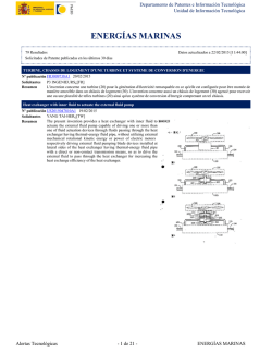
A wave energy extraction device
Nº publicación GB2515792A 07/01/2015
ADKINS NICHOLAS JAMES¿[GB]
Solicitantes
A wave energy converter comprises a floating wave operated member composed of two buoyant vessels 1 and connecting
Resumen
supports 3, and an inertial reaction member 2. The reaction member 2 is pivoted 4 about its centre of gravity, so that it has no
tendency to pendular or harmonic motion, about an axis parallel to the wave fronts. The pivots 4 are mounted on supports 3 on the
wave operated member. Energy is extracted from relative movement between the floats and the reaction member by e.g. hydraulic
cylinders 5a, 5b. Hydraulic pressure may be used directly for e.g. reverse osmosis desalination or a heat pump for liquid air
energy storage, or converted to electrical energy. The reaction member constitutes a large part of the total system mass, and the
mass may be concentrated away from the pivot axis to maximise the moment of inertia. The system may be operated without
contact with seabed or shore.
Alertas Tecnológicas
- 27 de 29 -
ENERGÍAS MARINAS
Departamento de Patentes e Información Tecnológica
Unidad de Información Tecnológica
Reducing bearing forces in an electrical machine
Nº publicación GB2515766A 07/01/2015
RODGER DAVID¿[GB]
Solicitantes
LAI HONG CHENG¿[GB]
A magnetic drive has a rotor 10 driven by a prime mover either via a
Resumen
rotor shaft (12 fig 1) or directly driven. The rotor 10 has a magnet
array on a surface thereof, and a further rotor 18 e.g. of a generator,
has a magnet array 504 on an outer surface thereof, which outer
surface of the rotor is located adjacent to the surface of rotor 10 such
that movement of the rotor 10 causes rotation of the rotor 18 about an
axis of rotation defined by a shaft 501 of a support member carrying a
mechanical bearing 505. Further magnet arrays form a magnetic
surface 28 on a flange 502 of the support member and a magnetic
surface 26 on the rotor. Interaction between these two surfaces forms a
magnetic bearing 506 to resist forces A18 acting along the axis of
rotation of the rotor. Alternatively the magnet surfaces may be
arranged radially inwards in the space 208 (fig 5a). Various array
arrangements of magnets on surfaces 26.28 are disclosed including a
Halbach array. Fig 15 (not shown) illustrates a repulsion force
magnetic bearing system used to offset the axial force on rotor 18.
Device for generating electricity 24/7 in all weathers
Nº publicación GB2515739A 07/01/2015
CHADWICK VAUGHN¿[GB]
Solicitantes
The device to generate electricity using several methods at once, in many climatic conditions, and during most hours of the day
Resumen
and night, is a tree-like object consisting of branches 1, and "leaves" 3 made of multi-layered composite material 4,5. The key
principle is to use layers of different materials to induce electricity by several methods at once such as: electrostatic charge
b u i l d - u p
p h o t o v o l t a i c
p i e z o e l e c t r i c
mechanical induction. The aim is to produce a device with a very high surface area so that low-yield approaches will generate
useful amounts of electricity. The device is flexible so that it will move even in light breezes. Twisting and bending motions will
induce an electrostatic charge and also induce a current in the piezoelectric layer. Use of multiple materials and colours will
contribute photovoltaic generation and also twisting which improves piezoelectric generation. The composite material may
comprise
an
outer
photovoltaic
layer
an
electropositive
static
material
in
a
darker
colour
a
middle
insulating
material
an electronegative static material in a lighter colour, and an outer photovoltaic layer.
CN204082432U
Nº publicación CN204082432U 07/01/2015
Alertas Tecnológicas
- 28 de 29 -
ENERGÍAS MARINAS
Departamento de Patentes e Información Tecnológica
Unidad de Información Tecnológica
SUPPORT FOR WATER TURBINE
Nº publicación JP2015500425A 05/01/2015
An underwater turbine mounting includes a rigid tether having one
Resumen
end attached thereto at a pivot, and the other end adapted for
connection to an underwater anchorage. The mounting is pivotable
between a deployment condition and an operating condition solely by
adjusting the buoyancy thereof.
DEVICE FOR CONVERSION OF MECHANICAL ENERGY FROM SEA WAVES TO ELECTRIC ENERGY
Nº publicación JP2015500412A 05/01/2015
Device (100) for conversion of mechanical energy from sea waves to
Resumen
electric energy, characterized by: - at least a float (101) and two rigid
rods (102), (103), preferably anchored at one end to the seabed (108),
and at the other end to the float (101) through flexible cables (106),
( 1 0 7 )
two respective masses (104), (105) keep the free ends of that rods
(102), (103), constantly in traction condition pulled towards the sea
b e d
( 1 0 8 )
- at least a power generator (109), or other similar device suitable to
convert and/or transmit energy, that is placed close to its respective
hinge (110), (111), placed at the bottom parts of the rods (102), (103),
so that the oscillatory motion of the float (101), following the waves
level (112), causes a force with a vertical component that leads to a
rotatory and oscillatory motion of the rods (102), (103), which are
pivoted on its respective hinge (110), (111), and generates therefore
electric energy by motion of gears of the same generator (109)
the horizontal component of the force due to the float (101)
oscillations is balanced by a system of counterweights, so that the
same float (101) tends to place itself constantly on vertical line A-A'.
Alertas Tecnológicas
- 29 de 29 -
ENERGÍAS MARINAS
© Copyright 2026