
AWUF Installation Manual
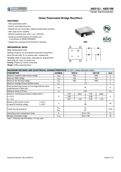
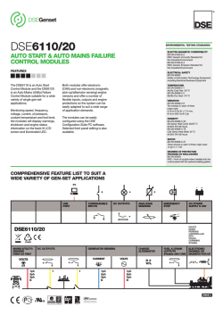
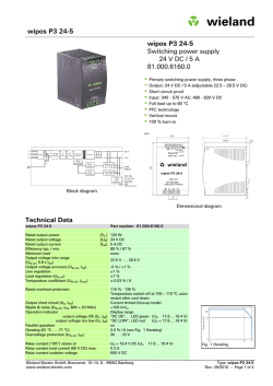
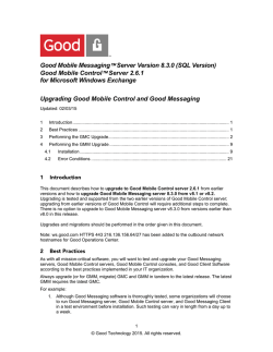
VERTICAL MOUNT AIR HANDLERS
INSTALLATION INSTRUCTIONS
Important Safety Instructions
As a professional installer, you have an obligation to know the
product better than the customer. This includes all safety precautions and related items. Prior to actual installation, thoroughly familiarize yourself with this Instruction Manual. Pay
special attention to all safety warnings. Remember, it is your
responsibility to install the product safely and to know it well
enough to be able to instruct a customer in its safe use.
Safety is a matter of common sense...a matter of thinking before acting. Most dealers have a list of specific, good safety
practices...follow them.
The precautions listed in this Installation Manual are intended
as supplemental to existing practices. However, if there is a
direct conflict between existing practices and the content of
this manual, the precautions listed here take precedence.
CARBON MONOXIDE POISONING HAZARD
Special Warning for Installation of Furnace or Air Handling Units in
Enclosed Areas such as Garages, Utility Rooms or Parking Areas
Carbon monoxide producing devices (such as an automobile, space
heater, gas water heater, etc.) should not be operated in enclosed areas
such as unventilated garages, utility rooms or parking areas because of
the danger of carbon monoxide (CO) poisoning resulting from the exhaust
emissions. If a furnace or air handler is installed in an enclosed area such
as a garage, utility room or parking area and a carbon monoxide producing
device is operated therein, there must be adequate, direct outside
ventilation.
HIGH VOLTAGE!
Disconnect ALL power before servicing or
installing this unit. Multiple power sources
may be present. Failure to do so may cause property
damage, personal injury or death.
This ventilation is necessary to avoid the danger of CO poisoning which
can occur if a carbon monoxide producing device continues to operate in
the enclosed area. Carbon monoxide emissions can be (re)circulated
throughout the structure if the furnace or air handler is operating in any
mode.
CO can cause serious illness including permanent brain damage or death.
B10259-216
-
Installations and repair of this unit should be
performed ONLY by individuals meeting the
requirements of an “Entry Level Technician” as
specified by the Air Conditioning, Heating, and
Refrigeration Institute (AHRI). Attempting to install
or repair this unit without such background may
result in product damage, personal injury, or death.
WARNING
To prevent the risk of property damage, personal injury,
or death, do not store combustible materials or use
gasoline or other flammable liquids or vapors in the
vicinity of this appliance.
CAUTION
This unit should not be connected to, or used in conjunction with, any devices that are not design certified
for use with this unit or have not been tested and
approved by the manufacturer. Serious property damage
or personal injury, reduced unit performance and/or
hazardous conditions may result from the use of devices
that have not been approved or certified by the
manufacturer.
IO-281L
10/2013
Have your contractor identify all the various cutoff switches
and devices that service this unit. Know where the switch is
that will cut off energy to the heating system in the event of
overheating.
Shipping Inspection
Pre-Installation Instructions
Upon receiving the product, inspect it for damage from shipment. Shipping damage, and subsequent investigation is the
responsibility of the carrier. Verify the model number, specifications, electrical characteristics, and accessories are correct prior to installation. The distributor or manufacturer will not
accept claims from dealers for transportation damage or installation of incorrectly shipped units.
Carefully read all instructions for the installation prior to installing product. Make sure each step or procedure is understood
and any special considerations are taken into account before
starting installation. Assemble all tools, hardware and supplies needed to complete the installation. Some items may
need to be purchased locally. Make sure everything needed to
install the product is on hand before starting.
Before attempting any installation, the following points should
be considered:
Codes & Regulations
This product is designed and manufactured to comply with
national codes. Installation in accordance with such codes and/
or prevailing local codes/regulations is the responsibility of the
installer. The manufacturer assumes no responsibility for equipment installed in violation of any codes or regulations.
The United States Environmental Protection Agency (EPA)
has issued various regulations regarding the introduction and disposal of refrigerants. Failure to follow these
regulations may harm the environment and can lead to
the imposition of substantial fines. These regulations may
vary by jurisdiction. A certified technician must perform
the installation and service of this product. Should you
have any questions please contact the local office of the EPA.
Structural strength of supporting members
•
Clearances and provision for servicing
•
Power supply and wiring
•
Air duct connections
•
Drain facilities and connections
Application Information
The unit is designed to be installed in conditioned space, either recessed into a wall or hanging in a vertical “upflow” position. If units are recessed in a wall, use the holes along the
inside of the front flange to attach units to the framing studs.
The vertical air handler comes equipped with an offset hanging
bracket attached to the rear of the cabinet for hanging applications.
The air handler also has a bottom and front return. Large chassis installations should be installed as front return only. If
the small chassis air handler is to be installed in a bottom
return application, discard the drain access panel in the bottom of the unit. If the air handler is to be installed in a front
return application, remove and discard the front access panel
with insulation. The unit is shipped with a filter rack and filter.
Remember to inspect, clean and/or replace the filter monthly.
Replacement Parts
When reporting shortages or damages, or ordering repair parts,
give the complete product model and serial numbers as stamped
on the product. Replacement parts for this product are available through your contractor or local distributor. For the location of your nearest distributor, consult the white business
pages, the yellow page section of the local telephone book or
contact:
CONSUMER AFFAIRS
GOODMAN MANUFACTURING COMPANY, L.P.
7401 SECURITY WAY
HOUSTON, TEXAS 77040
(877) 254-4729
Units are equipped with both a bottom primary and secondary
drain. Both drains must be trapped. Failure to install a trap
could result in condensation overflowing the drain pan resulting
in substantial water damage to the nearby area.
The connectors required are 3/4" NPT male, either PVC or
metal pipe, CPVC piping is not approved, and should be hand
tightened to a torque of no more than 37 in-lbs. to prevent
damage to the drain pan connection.
The installation and servicing of this equipment must be performed by qualified, experienced technicians only.
Installer’s Note:
To prevent potential sweating and dripping on to finished space,
it may be necessary to insulate the condensate drain line located inside the building. Use Armaflex® or similar material.
Replacement air filters can be ordered directly from the supplier:
United Air Filter
Charlotte, NC
Phone: 704-334-5311
AWUF18-24 AWUF30-37 -
•
NOTE: If you intend to install this unit with a “WAD” door
it must be mounted 1/4” behind front edge of stud.
Part #BT1369604,14” x 18” x 1”
Part #BT1369608,18” x 20” x 1”
2
Electrical Supply Wire and MOP
Maximum Allowable Length in Feet
to Limit Voltage Drop to 2%*
Wire Size
(AWG)
HIGH VOLTAGE
To avoid the risk of fire or equipment
damage, use only copper conductors.
Disconnect ALL power before servicing or
installing this unit. Multiple power sources may
be present. The electrical power to this unit
MUST be in the OFF position and all power supplies
disconnected. Failure to do so may cause property
damage, personal injury or death.
14
12
10
8
6
Minimum Circuit Ampacity (MCA)
10
75
118
188
301
471
15
50
79
125
201
314
20
37
59
95
150
235
25
NR
47
75
120
188
30
NR
NR
63
100
157
35
NR
NR
54
86
134
40
NR
NR
NR
75
118
45
NR
NR
NR
68
110
*Based on NEC 1996
Table 2
Maximum Overcurrent Protection (MOP)
The unit MUST have an uninterrupted, unbroken
electrical ground to minimize the possibility of
personal injury if an electrical fault should occur. The
electrical ground circuit may consist of an appropriately sized electrical wire connecting the ground lug
in the unit and control box wire to the building’s
electrical service panel. Other methods of grounding
are permitted if performed in accordance with the
“National Electric Code” (NEC)/”American National
Standards Institute” (ANSI)/”National Fire Protection
Association” (NFPA) 70 and local/state codes. In
Canada, electrical grounding is to be in accordance
with the Canadian Electric Code CSA C22.1. Failure
to observe this warning can result in electrical shock
that can cause personal injury or death.
Every installation must include an NEC (USA) or CEC (Canada)
approved overcurrent protection device. Also, check with local
or state codes for any special regional requirements.
Protection can be in the form of fusing or HACR style circuit
breakers. The Series and Rating Plate can be used as a guide
for selecting the MAXIMUM overcurrent device.
NOTE: Fuses or circuit breakers are to be sized larger than
the equipment MCA but not to exceed the MOP.
IMPORTANT NOTE: Torch heat required to braze tubes of
various sizes is proportional to the size of the tube. Tubes of
smaller size require less heat to bring the tube to brazing
temperature before adding brazing alloy. Applying too much
heat to any tube can melt the tube. Service personnel must use
the appropriate heat level for the size of the tube being brazed.
NOTE: The use of a heat shield when brazing is recommended
to avoid burning the serial plate or the finish on the unit. Heat
trap or wet rags should be used to protect heat sensitive
components such as service valves and TXV valves.
Inspection of the Building Electrical Service
This unit is designed for single-phase electrical supply. DO
NOT OPERATE ON A THREE-PHASE POWER SUPPLY.
Measure the power supply to the unit. The supply voltage
must be in agreement with the unit nameplate power requirements and within the range shown in Table 1.
Nominal Input
Minimum Voltage
Maximum Voltage
208/230
187
253
Electrical Connections – Supply Voltage
USE COPPER CONDUCTORS ONLY.
A knockout is provided on the air handler top panel or side to
allow for the entry of the supply voltage conductors. If the knockouts on the cabinet sides are used for electrical conduit, an
adapter ring must be used in order to meet UL1995 safety
requirements. An NEC or CEC approved strain relief is to be
used at this entry point. The wire is to be sized in accordance
with the “Electrical Wire and MOP” section of this manual.
Some areas require the supply wire to be enclosed in conduit.
Consult your local codes.
Table 1
Wire Sizing
Wire size is important to the operation of your equipment. Use
the following check list when selecting the appropriate wire
size for your unit.
•
Wire size must carry the Minimum Circuit Ampacity
(MCA).
•
Wire size allows for no more than a 2% voltage drop
from the building breaker/fuse panel to the unit.
Refer to the latest edition of the National Electric Code or in
Canada the Canadian Electric Code when determining the correct wire size. The following table shows the current carrying
capabilities for copper conductors rated at 75oC with a 2%
voltage drop. Use Table 2 to determine the voltage drop per
foot of various conductors.
3
8. Insert the suction line into the connection, slide the insulation at least 18" away from the braze joint. Braze suction line.
Special Instructions
This air handler comes equipped with an evaporator coil with a
check style flowrator assembly, an indoor blower and all necessary internal electrical wiring. For most installations with
matching applications, no change to the flowrator orifice is required. However, in mix-matched applications, a flowrator
change may be required. See the piston kit chart or consult
your local distributor for details regarding mix-matched orifice
sizing. If the mix-match application requires a different piston
size, change the piston in the distributor on the indoor coil
before installing the coil and follow the procedure in this section.
9. AFTER THE TAILPIECE HAS COOLED, confirm position of the white Teflon® seal and hand tighten the 13/16"
flare nut.
10. Torque the 13/16" flare nut to 10-25 ft-lbs or tighten 1/6th
turn.
CAUTION
Excessive torque can cause orifices to stick. Use the proper
torque settings when tightening orifices.
WARNING
11. Replace suction line insulation.
The evaporator coil is shipped from the factory with
approximately 90 PSI tracer gas charge. Use caution
when relieving pressure.
12. After installation, evacuation and charging of the low side
is complete, check fittings for leaks.
NOTE: With the piston in the distributor, the seal end should
point inside the distributor body and should not be seen when
looking into the end of distributor. Make sure the piston is free
to rotate, and move up and down in the distributor body.
CAUTION
To prevent feeder tube damage, hold the distributor body
with a 3/4" open end wrench when removing or replacing
the 13/16" flare nut.
MAINTENANCE
1. Remove the valve core to allow high pressure tracer gas
to escape. No gas indicates a possible leak.
Periodic Checkup and Service
This unit is designed to provide many years of dependable,
trouble-free comfort when properly maintained. Proper maintenance will consist of annual checkups and cleaning of the internal electrical and heat transfer components by a qualified
service technician. Failure to provide periodic checkup and
cleaning can result in excessive operating cost and/or equipment malfunction.
2. Remove the 13/16" flare nut and tailpiece.
3. Unsweat the access fitting on the tailpiece
4. Remove the check piston to verify it is correct and then
replace the piston. See piston kit chart in instructions.
5. Unsweat the cap on the suction line.
6. Slide the 13/16" flare nut over the tailpiece.
7. Braze tailpiece to the lineset liquid tube.
4
SUCTION LINE
LIQUID LINE
REMOVABLE
SERVICE DOOR
FRONT ACCESS
PANEL
SMALL CHASSIS
BOTTOM PRIMARY AND SECONDARY
DRAINS CAN BE ACCESSED THROUGH THE
BOTTOM OF THE UNIT. (3/4" NPT FEMALE
CONNECTION)
NOTE: HAND TIGHTEN ONLY
CABINET DIMENSIONS
LARGE CHASSIS SMALL CHASSIS
2.5 & 3.0 TON
1.5 & 2.0 TON
A
B
C
D
E
36
24
21
19 7/8
15 7/8
5
36
20 3/16
16 1/8
16
11
NOTE: SPECIFICATIONS & PERFORMANCE DATA LISTED HEREIN
ARE SUBJECT TO CHANGE WITHOUT NOTICE
NOTE: Thermostat heat anticipator setting is 0.2.
W
Y
G
TAPE
W
Y
G
AWUF31/32
T2
T3
NOTE: Connect T1 to the Y
going to the outdoor unit.
T4
T1
TAPE
T5
T6
NOTE: Connect appropriate speed tap
(Pink/Purple/Yellow) to T1.
Refer to table below for speed tap selection
WIRE COLOR
BTUH
NOMINAL CFM
PURPLE
PINK
18,000
24,000
600
800
YELLOW
30,000
950
6
BLOWER CHART FOR VERTICAL MOUNT AIR HANDLERS
Model
AWUF18XX1/16A*
AWUF18XX16B*
AWUF24XX1/16A*
AWUF24XX16B*
AWUF30XX1/16A*
AWUF30XX16B*
AWUF310516XX
AWUF310816XX/
AWUF321016XX
AWUF36XX1/16A*
AWUF36XX16B*
AWUF37XX16A*
AWUF37XX16B*
Speed
CFM delivered against External Static Pressure
0.1"
0.2"
0.3"
0.4"
0.5"
High
750
730
690
650
595
Low
710
700
690
635
585
High
755
715
670
615
545
Low
740
700
655
595
535
High
880
845
810
770
735
Low
845
815
780
745
705
High
900
870
835
795
760
Low
865
835
800
765
725
High
1250
1195
1135
1085
1010
Low
1110
1055
1020
955
905
High
1255
1120
1100
1020
950
Low
1115
1010
990
900
820
T5
875
865
830
805
765
T4
1005
975
945
920
890
T3
840
795
785
745
700
T2
645
615
550
500
445
T1
645
615
550
500
445
T5
1090
1065
1040
1015
985
T4
1005
975
945
920
890
T3
840
795
785
745
700
T2
645
615
550
500
445
T1
645
615
550
500
445
High
1280
1190
1110
1010
930
Low
1170
1100
1030
950
890
High
1215
1145
1070
985
890
Low
1120
1065
1000
915
820
High
1326
1284
1232
1181
1115
Low
1086
1061
1028
996
950
T5
1385
1205
1130
1045
950
T4
1235
1180
1115
1040
955
T3
1165
1120
1075
1025
945
T2
1050
1010
970
930
860
T1
1050
1010
970
930
860
7
NOTE: SPECIFICATIONS AND PERFORMANCE DATA LISTED HEREIN ARE SUBJECT TO CHANGE WITHOUT NOTICE
Quality Makes the Difference!
All of our systems are designed and manufactured with the same high quality standards regardless of size or efficiency. We have designed
these units to significantly reduce the most frequent causes of product failure. They are simple to service and forgiving to operate. We use
quality materials and components. Finally, every unit is run tested before it leaves the factory. That’s why we know. . .There’s No Better
Quality.
Visit our website at www.daikincomfort.com, www.goodmanmfg.com or www.amana-hac.com for information on:
•
•
Products
Warranties
•
•
Customer Services
Parts
•
•
Contractor Program and Training
Financing Options
5151 San Felipe, Suite 500, Houston, TX 77056
© 2005-2009, 2013 Goodman Manufacturing Company, L.P.
is a registered trademark of Maytag Corporation or its related companies and is used under license. All rights reserved.
8


© Copyright 2026