
MARS
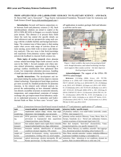
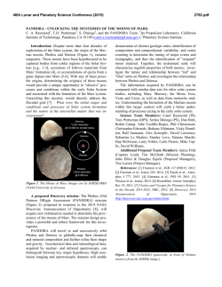
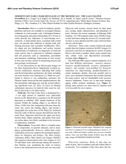
46th Lunar and Planetary Science Conference (2015)
2276.pdf
MARSDROP MICROPROBE ARCHITECTURE: BROADENING THE SCIENCE RETURN AND IN SITU
EXPLORATION FROM MARS MISSIONS. R.M.E. Williams1, M. A. Eby2, R. L. Staehle3, and R. Bhartia3.
1
Planetary Science Institute, 1700 E. Fort Lowell, Suite 106, Tucson, AZ 85719-2395, [email protected],
2
Aerospace Corporation, 3Jet Propulsion Laboratory—California Institute of Technology.
Introduction: The diversity of scientifically compelling targets on Mars has scarcely been explored in the
few landed spacecraft to date. Whether from the destination risks or just from the vast expense of a single
Mars lander, the majority of proposed scientific landing sites are eliminated from consideration. To help
bridge this shortfall, we propose an architecture to enable low cost delivery of small (~1 kg), useful scientific
payloads to designated spots on Mars as secondary
payload(s) on Mars-bound spacecraft. The Aerospace
Corporation’s and JPL’s experience with very small
reentry vehicles (Reentry Breakup Recorder [REBR],
and Deep Space 2 [DS2]) forms the starting point for a
passively stable entry vehicle, whose low mass/low
ballistic coefficient allows for a subsonic deployment
of a steerable parawing glider and guided flight for a
targeted landing (Fig. 1). In sum, MARSDROP represents
a new approach to augment Mars exploration by enabling precisely-targeted science at minimal cost for in
situ investigation at scientifically compelling locations
[1, 2]. Here, we discuss the scientific merit and capabilities of this approach, details of the MARSDROP architecture and technology demonstrations to date.
Science Motivation: The MARSDROP capability
enables a new class of Mars science investigations by
being able to deliver multiple miniaturized instruments
to the most desirable locations for network science,
ground truth studies, and enhances the search for
biosignatures by increasing the number of sample sites
The ability to steer to targets of interest during the gliding phase opens up a wide variety of enticing locations
including: a) within the canyons of Valles Marineris, b)
lava flows in volcanic regions such as Tharsis, c) water-transported sediment deposits in alluvial fans and
deltas9 (such as Eberswalde), d) proposed glaciers [3]
and ice-rich terrains, e) the subliming ‘Swiss cheese’
terrain of the southern polar cap [4], f) water carved
terrain from catastrophic floods (e.g., circum-Chryse
outflow channels), g) polar caps, h) potential geysers
that create spider-terrain in high southern latitudes [5],
i) bottoms of fresh impact crater sites [6] with high organic preservation potential, j) surface “windows” that
serve as skylights opening to subsurface ‘caves’ [7], k)
gullies[8, 9], and l) other surface changes, such as recurring slope lineae (RSL) [10] which may be signs of
seasonal subsurface water running down crater walls.
With multiple MARSDROP capsules on a single mission, there is the potential to create a distributed
weather station and/or seismic network. Taking advantage of periodic impact events (several occur annually), the interior structure of Mars can be probed. This
seismic data would complement forthcoming data from
the InSight mission and the ground penetrating radar
instrument (RIMFAX) on the Mars 2020 rover.
MARSDROP Architecture: The push for a viable
Mars microprobe landing architecture dates back to the
attempted, but unsuccessful, DS2 probes deployed
from Mars Polar Lander. While leveraging understood
technology, the overall approach of delivering miniaturized instruments using a self-guided gliding microprobe is a radical and unexplored departure from existing Mars exploration architectures.
MARSDROP enables low cost delivery of small
landers (~30 cm diameter probe, carrying a ~1kg scientific payload) to designated spots on Mars [1, 2]. Such
deliveries would piggyback on Mars-bound spacecraft,
making use of often-available excess launch vehicle
and cruise-stage mass capability, analogous to the DS2
probes. The Aerospace Corporation’s successful, very
small Earth Reentry Breakup Recorder (REBR) vehicle2 forms the starting point for a low mass/low ballistic
coefficient entry system that allows for subsonic deployment of a steerable parawing glider, capable of up
to 10 min and 10 + km of guided flight and impact the
surface with a 3:1 glide ratio at ~20.5 m/s. An imaging
system melded with an autonomous terrain-relative
navigation/control system and a tiny Electracompatible radio enable landing within tens of meters
of one of several specified targets within a 95% probability 53 x 8 km target ellipse5 and return of megabits
of data. The relatively low cost (estimated $20 – 50
M) of each probe, combined with an ability to send
multiple, redundant probes enables access to regions of
Mars deemed scientifically interesting, but too risky for
a large, expensive lander.
To study the viability of the concept, The Aerospace Corporation has conducted proof-of-concept
tests from high-altitude balloons. At ~100,000 feet
(~30 km) we find an ideal laboratory replicating the
Martian atmosphere, a cold and thin atmosphere with a
density a scant 1% of that at sea level on Earth. The
minimal size and weight of the probe, combined with
subsonic test speeds, permit the use of standard weather balloons, minimizing test costs. A mock capsule,
fitted with the proposed landing architecture, is attached to a weather balloon, which tows the vehicle to
46th Lunar and Planetary Science Conference (2015)
a 20 mile (~32 km) altitude. Cutting free from the balloon, the capsule free falls briefly until it matches the
speed (~400 mph; ~640 km/hr) and dynamic pressure
(~200 Pa) it would see during parawing deployment on
Mars. During backshell deployment, inflation loads are
measured with a 100-g accelerometer, while GPS readings track the probe’s forward and vertical velocity
during its descent. These tests showed that the
parawing constructed could withstand deployment dynamic pressure without damage, and the landing system
fits within the capsule, leaving sufficient volume and
mass for a useful landed payload.
The team has begun exploring plausible payload instruments that fit within the capsule (30 cm diameter,
~1 kg payload). Small, lightweight radios, scientific
instruments from seismometers to a lab-on-a-chip,
cameras, and higher-energy-density batteries all advance the utility of the landed mass far beyond DS2
capability. The breadth of viable instrumentation
ranged from high resolution science-grade and mineralogy cameras, to simple weather instrumentation, to
environmental sensors for near-surface atmosphere
characterization, to focused derivatives of organicssearch instrumentation. For example, the team is considering a miniaturized version of the deep UV fluorescence SHERLOC instrument that was recently selected
for the Mars2020 lander and is capable of characterizing trace organics and astrobiologically relevant minerals on unprepared rock surfaces [11]. Many of these
2276.pdf
instruments are considered feasible in the near-term to
meet the space constraints and tolerate the rigors of
space flight and landing.
Summary: The MARSDROP architecture can double or triple the number of Mars landers at small additional cost for each mission opportunity. With a guided flight capability, the payload can be delivered to
regions previously considered high-risk. In addition,
this targeted delivery enables distributed network science applications and could provide reconnaissance
data for future missions. In short, this delivery system
can dramatically enhance the scientific return of Mars
exploration, providing access to sites of high geologic
and astrobiologic interest.
References: [1]Staehle, R. L. et al. (2014) 65th International
Astronautical
Congress,
http://www.iafastro.net/iac/paper/id/22457/summary/
[2] Staehle, R. L. et al. (2014) Mars CubeSat Workshop. [3] Garvin, J. B et al., 2006, Meteoritics &
Planetary Science, 41. 1659-1674.. [4] Malin, M. C., et
al., Science 294, 2146-2148. [5] Kieffer, H. H., et al.,
2006, Nature 442, 793-796. [6] Malin, M. C., et al.,
2006, Science 314, 1573-1577. [7]Cushing, G. E.,
2007, LPSC #1371., [8] Dundas et al., 2010 GRL. [9]
Malin, M. C. and K. S. Edgett, 2000, Science, 288,
2330-2335. [10] McEwen et al., 2011, Science, 333,
740-743. [11] Beegle, L. W. et al., (2014) LPSC. Abstract #2835.
Figure 1: A) MARSDROP microprobe landing architecture. B) MarsDrop balloon test descending to Nevada desert
floor superimposed on MER scene. Image “color matched” to Mars. C) Engineering team holding parawing with
balloon test article on table.
© Copyright 2026