
MRO/HIRISE RADIOMETRIC CALIBRATION UPDATE. M. P. Milazzo
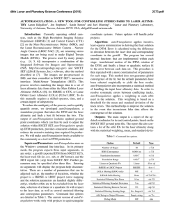
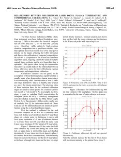
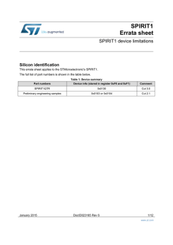
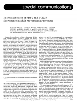
46th Lunar and Planetary Science Conference (2015)
1498.pdf
MRO/H I RISE R ADIOMETRIC C ALIBRATION U PDATE . M. P. Milazzo1, , K. Herkenhoff1 , K. Becker1 , P. Russell2 , A. Delamere3 ,
A. S. McEwen4 ; 1 Astrogeology Science Center, U.S. Geological Survey, 2 Smithsonian Institute, 3 Delamere Support Services,
4
University of Arizona; ([email protected])
Introduction: The High Resolution Imaging Science Experiment (HiRISE) onboard the Mars Reconnaissance Orbiter (MRO)
[1] has been observing Mars since 2006 and has acquired more than
38,000 observations of the martian surface. The HiRISE instrument is a pushbroom imaging system made up of fourteen linear,
two-channel, Charge Coupled Devices (CCDs). Ten 2048-pixelwide CCDs with a broadband red filter (RED CCDs) are laid sideby-side with an overlap of 48-pixels on each side for a total of
20,264 pixels. In front of and behind the RED CCDs, as viewed
in the along-track direction, are four more CCDs, two each with a
blue-green (BG CCDs) and near-IR (IR CCDs) filter respectively
(Figure 1). The HiRISE instrument thus consists of 28 separate
channels calibrated independently.
Radiometric calibration is a critical step in image analysis;
without it, quantitative comparisons of colors and brightnesses between observations and between instruments would be impossible.
To-date, because of a lack of accurate radiometric calibration, most
martian studies using HiRISE images have been morphological in
nature. Once radiometric calibration has been finalized, inter- and
intra-instrument brightness, color, color-ratio, and spectral studies
will be possible. For example, quantitative comparisons between
the high-spectral-resolution imaging spectrometer, CRISM (Compact Reconnaissance Imaging Spectrometer for Mars) and the highspatial-resolution HiRISE will be possible [2].
The two channels on a given CCD are commanded with identical imaging parameters but contain separate electronics, so require
independent calibration parameters. The two main imaging parameters that affect radiometric calibration are TDI (Time Delay and
Integration) and binning. TDI is a method for increasing signal by
capturing up to 128 lines of data over a single ground point; TDI
modes of 8, 16, 32, 64, and 128 are possible. Each CCD may be
binned over 2x2, 4x4, or 8x8 blocks of pixels, increasing signal to
noise at the expense of spatial resolution. The calibration routines
operate on each of these TDI, BIN combinations for each of the
28 CCD channels. A schematic of a HiRISE channel’s calibration
data is shown in Fig 2:
Figure 1: Schematic of the HiRISE Focal Plane Array. The IR
CCDs observe the ground first, then the RED CCDs, and finally
the BG CCDs.
* Pre-Observation Lines: For each sample, data are acquired
immediately before the image observation lines from three
distinct calibration sources.
– Reverse Clock Pixels: 20 lines of offset signal.
– Masked Pixels: charge generated in the active area of
the CCD is transferred, one line at a time, through 20
lines of pixels behind a mask.
– Ramp Lines: Number of lines equally to TDI ÷ BIN.
These include initial signal from the reverse and forward clocking through the CCD. For a flat target and no
dark current or offset, the last Ramp line should have
twice the signal of the image line immediately following.
* Pre-Image Samples: The Buffer Pixels comprise 12 samples read out of the serial register before each image line.
These Buffer Pixels only contain serial dark current and offset.
* Post-Image Samples: The Dark Pixels comprise the 16 pixels at the end of each line of the CCD. These pixels were
masked from exposure by metallization deposited onto the
CCD and should only contain serial and parallel dark current
and offset signal.
Radiometric Calibration: Below, we describe the radiometric calibration requirements and what has been accomplished to
date to meet those requirements. Updated analyses will be presented at the conference in March.
Scattered Light: The HiRISE baffle system was designed for
the minimization of scattered light from the disk of Mars with a
goal of less than 2% of the nominal signal. HiRISE acquired observations of Phobos for analysis of scattered light. Scattered light
was undetectable in the well-planned images, and from those analyses we conclude that scattered light contributes at most 0.22% and
more probably 0.1% or less.
Figure 2: Schematic of the structure of the raw HiRISE image
channel as delivered to the PDS.
46th Lunar and Planetary Science Conference (2015)
Relative (Pixel-to-Pixel) Calibration: The requirement for
HiRISE relative calibration was that calibrated pixels would exhibit better than 1% pixel-to-pixel accuracy for 99.5% of the pixels
within each CCD and across the FOV when using 128 lines of TDI.
Relative accuracy of 1% is required over a 10-second image exposure.
Flat-field calibration data were acquired in the laboratory before launch and at Mars by yawing the spacecraft 90-degrees to the
direction of travel. These data indicate a relative pixel-to-pixel accuracy of less than 0.5%. A more accurate number, with full error
analysis will be presented at the conference.
A 10-second exposure of an average brightness surface will
produce an observation of approximately 100,000 lines, assuming 100 µs line exposure time which is typical of science imaging.
Night-side calibration images were generally taken with fewer lines
for a number of operational reasons. On a 2.5-second exposure,
electronics-induced noise drifts by approximately 1.7% (∼20-DN),
but this effect is measurable using the Buffer Pixels. Our accuracy
in correcting the drift for a night-side, dark image is approximately
1.4% (∼20-DN) over 2.5-seconds, though the largest drift occurs
during the first 1-second (10,000 lines) and there appears to be minimal drift after about 50,000 lines. The absolute value of this error in measuring the drift is independent of the target (because it
is electronics noise rather than photon-generated), and is approximately 20 DN. For a well-exposed science image with average DN
of 4000 or more, the error is 0.5% or better.
The analysis of the relative calibration across the full observation FOV will be presented at the conference. At this time, we are
confident that the Reduced Data Records (RDRs) released to the
PDS have relative accuracy on a per-channel-basis of 1% or better
for a well-exposed surface image with TDI=128 and better than 2%
across the FOV.
Absolute Calibration: The absolute calibration accuracy requirement was 20% or better in all channels using 64 TDI lines.
Because HiRISE is a linescan/pushbroom imaging system, standard stellar calibration targets are not as useful for absolute radiometry as they are for framing cameras. The special calibration sequence we performed with Jupiter is phase-, time-, and thus modeldependent. Special calibration sequences with the Moon and Earth
have proven difficult to analyze due to imaging geometry and because the observations taken during cruise have few comparable
observations during science operations. The martian moons have
been observed by too few independent instruments for high quality
comparisons. We have been forced to compare HiRISE images of
the martian surface with much lower-resolution imaging systems
such as Hubble, CRISM, and MARCI. Our absolute calibration is
within 20% of the calibration of those instruments, but we have not
yet verified the calibration against well-established standard calibration targets.
Spectral Response: As a goal, the relative spectral response
of each pixel over the entire FOV should be 5% accuracy from 400
1498.pdf
to 1100-nm in steps of 50-nm. Calibration of the spectral response
is similarly complicated by the lack of standard calibration targets.
Based on laboratory measurements before launch, the relative spectral response of the three HiRISE filters is 4%.
Signal to Noise Ratio: The requirement for signal to noise
(SNR) is 100:1 for RED CCD data acquired at 300-km altitude
when imaging the martian surface with average albedo of 0.25, 70degree incidence angle, and when Mars is at its average distance
from the sun (1.5 AU) with imaging parameters of 128 TDI and
BIN 1. For the same situation, the BG CCDs (except with an average albedo of 0.1) are required to have SNR of at least 25:1 and the
IR CCDs 50:1. The HiRISE SNR is generally much higher (200:1
or better for the RED CCDs and 50:1 or better for the IR and BG
CCDs).
Conclusions: Results are summarized in Table 1.
Software: HiRISE Experimental Data Records (EDRs)
are processed through the HiRISE Operations Center (HiROC) via
a series of custom processing steps [3]. The key processing step is
the U.S. Geological Survey Astrogeology Science Center’s ISIS3
application hical [4]. hical is the software that produces nominally
calibrated products from the EDRs in the form of I/F or calibrated
radiance values.
Additional Complications: Beyond instrument response,
the martian atmosphere is variable from observation to observation
and its effects are not included in these calibration efforts. Atmospheric effects must be accounted for when performing color ratios,
comparing observations taken at different times, or comparing between multiple instruments.
References:
[1] McEwen, AS, et al. Journal of Geophysical Research, 112
(2007). doi:10.1029/2005JE002605. [2] Seelos, F, et al. AGU
Fall Meeting Abstracts, vol. 1, p. 1714 (2011). [3] Eliason, E,
et al. Lunar and Planetary Institute Science Conference
Abstracts, vol. 38, p. 2037 (2007). [4] Becker, K, et al. Lunar
and Planetary Institute Science Conference Abstracts, vol. 38,
p. 1779 (2007).
Table 1: Preliminary Calibration Results
Calibration
Requirement
Result
Scattered Light
2%
< 0.22%
Relative
1%
1 − 2%
Absolute
20%
Uncertain, ∼ 20%
Spectral
5%
4%
SNR
100 : 1
200 : 1

© Copyright 2026