
a simple technique for fine-scale, vertical sectioning of fresh
Made in United States ofAmerica
Reprinted from JOURNAL OF SEDIMENTARY PETROLOGY
Vol. 58, No.4, July 1988
© 1988 by The Society of Economic Paleontologists and Mineralogists
A SIMPLE TECHNIQUE FOR FINE-SCALE, VERTICAL SECTIONING OF FRESH SEDIMENT CORES 1
CHARLOTTE M. FULLER AND CHERYL ANN BUTMAN
Ocean Engineering Department
Woods Hole Oceanographic Institution
Woods Hole, Massachusetts 02543
INTRODUCTION
Biogeochemical processes occurring at the sediment-water interface
and within the very near-surface sediments are known to affect or control
what occurs above or below the sediment surface (see reviews ofNowell
1983· Jumars and Nowell 1984; Nowell and Jumars 1984; Grant and
Mad~en 1986; Butman 1987; Rumohr et a!. 1987). Studies of these
phenomena often require vertical sampling of the variables of interest
over very fine (e.g., millimeter) spatial scales. Existing techniques for
such fine-scale vertical sectioning of fresh sediment cores were developed primarily for studies of porewater chemistry (Craven et a!. 1986;
Jahnke et a!. 1986; Reimers and Smith 1986) and of the distributions
of meiofauna or microbes (Boaden and Platt 1971; Joint et a!. 1982;
Palmer and Molloy 1986), where only very small samples (cores ::53.0
em in diameter) are required. Furthermore, in most cases, the verticalsectioning technique requires subcoring a much larger sediment sample
(e.g., a box core) after it is taken. This potentially introduces error
(contamination between layers) when sectioning at millimeter intervals,
because near-surface sediments within the sample may mix vertically
1
Manuscript received 14 September 1987; revised 29 February 1988.
or horizontally on transit to the water surface (Rutledge and F1eeger
1988).
We here describe a technique for fine-scale vertical sectioning offresh
sediment cores that operates on the same general principle as many
previously described core extruders but that can be used on larger cores.
We also describe a technique for subcoring a box core while it is taking
a sample, to avoid errors which may be introduced by subsampling on
deck. The precision (in terms of vertical positioning, contamination
between adjacent layers, and smearing) of this extruding technique is
discussed, based on results of laboratory calibration experiments using
muddy sediments.
EXISTING TECHNIQUES FOR FINE-SCALE
VERTICAL SECTIONING
Existing techniques to extrude and section fresh sediment cores at
scales of millimeters (1-50-mm sections) involve the use of small (1050 ml), disposable or reusable syringes (Boaden and Platt 1971; Joint
eta!. 1982; Craven eta!. 1986; Jahnke eta!. 1986; Palmer and Molloy
1986; Reimers and Smith 1986). In most cases, the syringe barrel was
~sed to subcore a larger sedimeQ.t sample (box core or grab), exceptions
being Boaden and'Platt (1971) and Joint eta!. (1982), where intertidal
CHARLOTTE M. FULLER AND CHERYL ANN BUTMAN
764
A
/
J
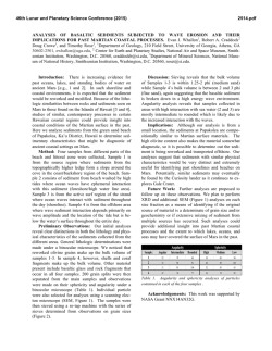
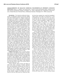
FIG. 1.-A) Diagram of a
0.25-m 2 MK-3 Hessler-Scandia box core, showing core
holders in the central nine sections of the vegematic. The
front panel of the box core has
been removed to expose the
vegematic sections; a cut-away
view of one section shows the
core tube inside. B) Expanded
view of core holder and bottom support in a vegematic
section of a box core; see text
for detailed description.
sands were cored with the syringe barrel directly. In all cases, the syringe
plunger was inserted into the bottom of the syringe barrel containing
sediments, and the sample was extruded through the top of the barrel,
either by turning a micrometer screw (Joint et al. 1982; Palmer and
Molloy 1986) or by simply pushing on the plunger (Boaden and Platt
1971; Craven et al. 1986; Jahnke et al. 1986; Reimers and Smith 1986).
The vertical resolution afforded by a given coring technique depends
on both the extent of core shortening and the vertical mixing of sediment
layers within the cores (e.g., see Wrath 1936; Piggot 1941; Emery and
Hulsemann 1964; Hongve and Erlandsen 1979; Lebel et al. 1982; Weaver and Schultheiss 1983; Blomqvist 1985; Rutledge and Fleeger
1988). The most recent results indicate that the depth at which core
shortening begins is positively correlated with core diameter, suggesting
that the sediment depth to which accurate, fine-scale, vertical resolution
may be expected decreases with decreasing core diameter (Blomqvist
1985). Furthermore, the very near-surface sediments tend to concentrate
in the center of the samples as they are brought to the water surface
(due to inadvertent shaking and jostling of the samples, even when
carefully transported by divers) (Rutledge and Fleeger 1988), so subsampling a larger core or grab once it is on deck could introduce error
if small-scale vertical resolution is required. The magnitude of both
phenomena depends on the sediment-sampling technique, as well as on
the sediment texture and environmental conditions at the time ofsampling. Particularly vexing, however, is that the existence of clear water
above the sediment surface when the sample is brought on deck does
not necessarily indicate an undisturbed sample (see Elmgren 1973).
Thus, to minimize these potential problems when attempting to discern
fine-scale vertical gradients in sediment grain size, porewater chemistry,
and organism abundance, we designed a subcoring technique that eliminates the potential error associated with subsampling after the sediments are brought on deck and an extruder that could be used to vertically section relatively large-diameter cores.
THE CORING AND SUBCORING TECHNIQUE
Initially, field cores taken by scuba divers in shallow water (depth,
10m, Buzzards Bay, Massachusetts) for biological and sedimentological
analyses were made of clear-cast acrylic tubing, with an inside diameter
of 3.9 em and a wall thickness of 6.5 mm. The acrylic material and
relatively large wall thickness were chosen to minimize distortion of the
core during the extruding process. Later we learned that nondistorting,
thinner walls were possible if we used polycarbonate (sold under the
trade name Lexan), which is more rigid than acrylic, so we currently
use polycarbonate cores with a 3.8-cm inside diameter and a 3-mm-wall
thickness. The bottom, outside perimeter of the cores are beveled to
minimize disturbance to surface sediments when the core is initially
inserted into the seabed.
To obtain cores for fine-scale vertical sectioning using a shipboardoperated sampling technique, we modified the vegematic sections of a
0.25-m 2 MK-3 Hessler-Scandia Box Core (Ocean Instruments, California; see initial description in Hessler and Jumars 1974) to hold our
shallow-water core tubes. The 25 vegematic sections each measure 10
em by 10 em (outside dimensions) and hang in the box by aluminum
rods which run horizontally through tabs at the top of the sections (see
Fig. lA). The rods thread through permanent cross supports which limit
the extent to which the sections are pushed up during sampling. Aluminum core holders (Fig. 1B) were machined to fit inside the vegematic
sections; the core holders have tabs with holes so that they also hang
from the removable rods.
The core holders (refer to Fig. lB) were designed for our 3.8-cmdiameter polycarbonate cores. Each core holder is a solid piece of aluminum 9.3 em square and 2.2 em thick so that it fits snugly inside a
vegematic section. The top of the core holder also has a small lip (2
mm wide and 1 mm thick) on two sides so that it can rest on top of
the vegematic section, and it has an indentation on one end to fit under
the permanent cross supports. The core holder is split in the middle so
that it can be slid onto a core and tightened with a bolt. The underside
of the core holder contains a 4.4-cm-diameter hole where the core is
inserted. A fine-mesh screen (400-J.Lm-square openings) is inserted into
this hole to reduce sloshing but also to allow water to escape out the
top of ~)le core when the box core is biting .. The screen is supported by
a 3-mm lip around the periphery of the core hole, so that the diameter
of the opening looking down at the top of the core holder is 3.9 em,
slightly larger than the inside diameter of the core. The core holder
contains four 1.5-mm-diameter holes in the comers, also for water
escape.
For long cores, we also clamp on a cross-bar support (see "bottom
support" in Fig. 1B) near the bottom of the core. The most important
feature of this cross bar is the beveled end of each strut that fits precisely
into the corners of the vegematic section to hold the biting end of the
core securely in the center of the vegematic section.
The core holders can be inserted into any or all of the vegematic
sections of the box core, depending on the number of samples required.
The length of core needed to obtain the required sample depth depends
on the depth of penetration of the box core. We usually mount both
13-cm- and 37-cm-long cores on the first deployment; the short cores
RESEARCH METHODS PAPERS
Threaded r o d - - - -
765
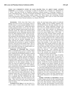
another plastic collar that fits around the core and tightens with set
screws to hold the core in place.
Near the top of the core is a polycarbonate mud catcher, which is
donut shaped and fits snugly around the outside of the core. A tight
seal, made by an o-ring set in a groove very close to the upper edge of
the mud catcher, prevents any loss of the sample and also holds the
. ring in place. The mud catcher has a hollowed-out trough and spout to
catch the sample. A thin ( -1-mm-thlck) but rigid sheet of aluminum,
held vertically to minimi21e smearing of the sample, is used to slice the
extruded sediment off the top of the core into the mud catcher. The
sample is then washed down the spout of the mud catcher into a collection container.
This extruder was designed for the cores used in our field studies (see
Butman and Grant 1986; Grant and Butman 1987) but is not limited
to use on relatively small cores as are the more delicate, syringe-type
extruders. The rugged construction of the screw assembly allows for
precise, fine-scale sectioning even at sea. Virtually any core of reasonable
size can be' sectioned using this technique, as long as the piston fits
tightly inside a sufficiently inflexible core tube.
CALIBRATION EXPERIMENTS
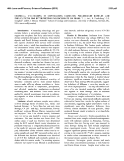
Position indicator
FIG. 2.-Drawing of the core extruder; see text for detailed description.
are preferable, to minimize sample processing time, if the box-core
sample is deep enough. As each vegematic section of the box core is
removed after sampling, the cores are capped on the bottom (by digging
out the mud from below) before the core holder is removed. Thus far,
we have successfully used this technique for obtaining fine-scale vertical
sections of bottom sediments at depths between 80 m and 400 m along
the southern California coast, where sediments ranged between almost
entirely sand to almost entirely mud.
THE CORE EXTRUDER
The core extruder is shown in Figure 2. It consists of a stand and
clamp to -hold the core vertical, a tight-fitting piston which is pushed
up by turning a threaded rod, and a "mud catcher" for washing the
extruded sample into a collecting vessel. M. H. Bothner and M. C.
Woodward provided valuable advice on the design and construction of
the core extruder.
The piston is a clear-cast acrylic rod slightly smaller than the inside
core diameter. 0-rings are set in grooves near each end of the piston to
ensure stability and a tight seal between the piston and the core. The
piston is pushed up through the core by a threaded rod which turns
freely in an indentation in the bottom of the piston. The rod is -machined
so that one complete tum pushes the piston up 2 mm. A pointer attached
to a washer sits on top of the screw knob at the bottom of the rod to
indicate the rod position. The pointer is free to rotate around the rod
so that it can be zeroed when the sediment surface is flush with the top
of the core; then the pointer is clamped in place so that it rotate~ with
the screw knob. The rod threads through a tapped plastic collar which
is mounted on the extruder stand. Attached to the tapped collar is
Calibration cores consisting of sediment layers increasing in grain
size downcore were assembled and extruded in the laboratory in an
attempt to define the precision of this core-extruding technique. The
sediments were collected from the field (intertidally from Sippewissett
Marsh, Massachusetts, in the first experiment and at 10-m depth from
Buzzards Bay in all others), frozen at least overnight, thawed and wetsieved through nested screens. Since there were no live animals to rework
the sediments, and thus change the layering of the m-ud, these calibration
cores indicate the maximum error introduced by the extruder itself(e.g.,
by smearing of the sample along the core wall) and by laboratory technique (sieving and layering).
Error introduced by our wet-sieving technique was estimated by resieving a subsample of.each presieved size class of sediment for use as
controls. Error introduced by our sediment-layering technique was estimated by measuring the height of each sediment layer at several points
around the outside perimeter of the core, assuming that the interface
between sediment layers, as viewed from the outside of the core, was
representative of the sediment interface in the core interior (the validity
of this assumption will be discussed later).
All sediment sieving was done very gently by the same individual,
using prefiltered seawater (particles > 5 11m were removed), and care
was taken to minimize breakage of natural aggregates. This sieving
technique was chosen for the grain-size analyses, as opposed to a more
classical grain-size analysis technique (e.g., using a disaggregant, such
as Calgon, and pipette analysis; see Folk 1980), because it would be
used in subsequent applications of the core extruder for sediment-transport studies, to determine the size of natural particulates in the very
surface sediments (i.e.; in the "resuspendable" fraction; see Grant and
Butman 1987). Sediments were sieved into the following fractions:· <45,
45-63, 63-300, ~300 11m (Expt. 1); and <20, 20-45, 45-63, 63-90,
90-180, 180-300, ~ 300 11m (Expt. 2). The second set of sieve sizes was
chosen to maintain an approximately constant fall-velocity interval; if
the 45-63- and 63-90-!Lm-size classes are combined, then successively
larger size classes represent about a four-fold increase in fall velocity,
with the exception of the largest- and smallest-size-class intervals. The
63-!Lm sieve was used to divide the 45-90-!Lm classes in two, for comparative purposes, because 63 11m is the cutoff between silt and very
fine sand.
In these experiments, the sediment fractions were added to the cores
in layers -4 mm thick, except for the bottom layer next to the piston,
which was -8 mm thick (to separate the analyzed sections from the
piston). Each layer was carefully introduced by a pipette held just beneath the seawater surface. Generally each layer was allowed to settle
several hours before adding the next layer, but in Experiment 2, each
layer sat for only one hour before addition of the next sediment layer.
In one experiment, a thin marker layer of white kaolin china clay was
sprinkled on top of each layer to identify clearly the interface between
layers. These marker layers were useful for qualitatively assessing the
extent of smearing during the extrusion process, but they contaminated
the sediment fractions by settling into pore spaces between all layers,
so only results of Experiments 1 and 2 will be discussed quantitatively.
Before a core was extruded, it was photographed, and the depth of
CHARLOTTE M. FULLER AND CHERYL ANN BUTMAN
766
Sediment
Layers
<44 p.m
Percent of Each Size
Class (I'm) Per 2mm Layer
(Expected Percent
Contamination)
Measurement Points Around Core
I
4
2
3
4
0
<44
"t3
~
99.6
0.4
99.6
0.4
-------------~~~~,.]4
~
~
0.9
f.3
96.9
99.7
0.3
2.4
95.2
2.4
02
0.3
980
1.5
0
0
0.6
99.4
<44p.m
44-63p.m
0.8
0.4
0.4
53.9 45.3
0.1
0.1
20.4 79.4
8 ----- ---------
10
·=
12 ;:
- - - - - - - - - - - - - - - - - - - - - - - - - - - 14
C>
63-300p.m
- - -- -- -- - - _l4~J-
~
300- 2,000 p.m
Control
Sediments
E
4.3 83.6 ii?,5L
12.1
.5 _______
__ _
CD
- ---- --- -- -- - ------ ---- - -
Control'' Sediments
7.4
------------------------- 6
Itz~========'2':2~~~~~
~
8
63-300p.m
11
---- JI?Ql __ -----23.6 69.0
44-63 p.m
Percent of Each Size
Class (I'm) for
~0 ~
--------------------------- 2
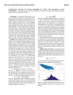
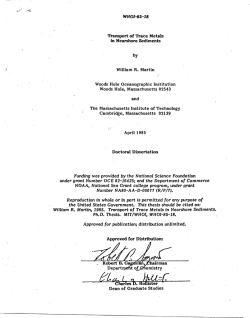
F1o. 3.-Results of the first
calibration experiment, showing initial layering of sediments (left), grain-size distributions recovered in the
extruded layers (middle), and
grain-size distributions of the
control sediments (right). The
dashed lines in the diagram on
the left indicate the 2-mm sectioning intervals. The shaded
regions are the "expected percent contamination" of sediments within a given 2-mm interval by sediments in the layer
below, as indicated by measurements of the layer interfaces around the core perimeter. The expected percent
contamination (shown in parentheses under the appropriate grain-size class of the extruded sediments in the middle
table) wa~ calculated by unrolling the core perimeter into
a rectangle of unit width and
using simple geometric shapes
to represent the contaminated
regions. "Uncontaminated"
horizons are those 2-mm sections which contain ·no shading.
--------------
0.1
0
2.8
97.0
- - - - - - - - - - - -- - - - - - - - - - - - - 16
18
20.
L-----~--~----~----~22
~
= Region Contaminated by Sediment
Layer Below
--- = 2 mm Layers Extruded
each sediment layer was measured at several (four in Ex pt. I, and eight
in Expt. 2) points around the core to 0.5 mm (using a ruler in Expt. I)
or to 0.1 mm (using calipers in Expt. 2). The seawater above the sediments was removed by pipette. before the sediment column was pushed
up so that it was level with the top of the core. In these calibration cores,
the sediment surface· was flat, with irregularities on the order of tenths
of millimeters. The core was extruded at 2-mm intervals. Sediments
from each layer were gently washed, with 5-!Lm prefiltered seawater,
through the same series of nested screens used to define the size class
of the layers for that particular calibration core. The material on the
sieves was either vacuum filtered onto preweighed 0.45-!Lm filters (when
very small amounts of a size fraction were collected) and rinsed with
distilled water, or was rinsed with distilled water into preweighed aluminum pans. The filters and pans were dried at -60°C to a constant
weight.
Results of the calibration experiments indicate very little error associated with the extruder itself. Since the screw that pushes the piston
up the core was machined to an accuracy of greater than 0.00 I mm,
any inaccuracy in the layer thickness is due to the positioning of the
pointer. The pointer can easily be returned to within 5° of its original
position, which would result in a maximum error of about one percent
for one complete turn of the screw (or 0.02 mm in a 2-mm section).
Percent of Each Size Closs (fJJn}
Percent of Each Size Closs (J.lm)
Per 2-mm Layer
for
11
Control" Sediments
(Expected Percent Contamination)
Measurement Fbints Around Core
Sediment
Layers
<20/'ffi
I
-------------------
<20
2~5
965
1.5
"g;3
6~0
91g0 18£o >300
<20
a3
20- 4
45
6
~o
1go ~~o >300
68.8 29.9
1.3
-· -- 111-:ll---------- - - 20-45/'ffi
-------------------
6
~--~---~--..J8
10
"E
..5
~
9.8 871 3.1
_IQ..2L - - - - - - - - - - - - - - 17.7 29.2 51.0 2.1
- - - - - i2~6l - - - - - - - _.- 6.1
11.0 679 15.1
---»~------------6.0
c
63-90/'ffi
12
~
14
°
16
90-180/'ffi
20
12.6 75.6
92.1
2.8
3.7
12.6 80.5 3.1
3.1
3.0
2.6
1.8
1.5
6.5
5.6
4.6
1.7
- - - - - - - _{!O:Q)_-- - , - - - -
9.0
-
3.7
6.6 43.2 36.7
0.9
~6- ~= -3~2- ~= .f.i;l. ~-~ -0~5-
- 9~6_
180-300/'ffi
4.1
5.1
- 9~1
_
11.7 79.6 2.6
78 85.0
1.3
:~ _ 3~3_ :~ _3~0- n~j ~~3_
~ ~-~-3~9- :~ -~~~~l. ~2!- ~9-
Sediments
!
!
979 2.1
2·
Control
5.1
11.6 62.1
4.4
l
l
l
!
20-45 J.lm
45-63J.lm
63-90Jim
.. 1.1~
90-180 J.lm
180-300/'ffi
63-90/'ffi
---
~
lllllJ
2-mm Layers Extruded
Region Contaminated by Sediment
Loyer Below
Region Contaminated by Sediment
Layer Above
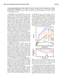
FIG. 4.-Results
for the second calibration experiment;
see caption to Figure
3 for explanation.
767
RESEARCH METHODS PAPERS
j
"\
Virtually no smearing of the core was observed during the experiment
where the white clay clearly marked the interface between layers. Furthermore, the mud catcher was effective in ensuring no loss of sample
during collection of each extruded layer.
In general, there was excellent agreement in the size-class distributions
ofthe initially layered and extruded sediments; the few large differences
can be explained by imprecision in our sieving or layering techniques
(refer to Figs. 3 and 4). The size-class distributions in the control sediments indicate the imprecision of our sieving technique. For the first
calibration experiment, the error introduced by sieving was less than
five percent (i.e., ~95% of the extruded sediments consisted of the
initially layered sieve-size class-the sediments were ~95% "pure").
When sediments were separated into smaller-size classes (Expt. 2), the
purity dropped to greater than or equal to 80 percent in all but the largest
size class (where the purity was only 62%), roughly increasing with
decreasing size class. This may reflect the breakdown of natural aggregates during processing. For Experiment 2, all extruded sediment layers
and control sediments were refrozen after sectioning, then thawed and
sieved several days later, whereas in Experiment 1, the sediments were
not refrozen before sieving. Thus, it is possible that refreezing and
thawing of sediments contributed to the breakdown of natural aggregates, resulting in lower purity for the larger-sediment-size classes.
The size-class distributions measured in the extruded sediments appear to reflect primarily the imprecision of our sieving technique (and
not errors introduced by the extruder), because all size classes represented in control sediments for a given layer also were retrieved in the
extruded sediments from that layer. In addition, there was excellent
quantitative agreement between extruded fractions and control fractions
in the ten layers which were not significantly "contaminated" (see caption to Fig. 3) by the sediment layer below (i.e., layers lacking a shaded
region making up > 2.5% of the area; see far left in Figs. 3 and 4); 77
percent of these extruded fractions agreed with the control fractions to
±3 percent. Thus, imprecision in sieving as indicated by the control
sediments, rather than smearing of the sample during extrusion, accounts for the extruded sediment grain-size distributions in all of the
uncontaminated sediment layers.
The control sediment grain-size distributions probably also account
for deviations between initially layered and extruded sediments in the
contaminated layers; however, the accuracy of our estimated percent
contamination of these layers (discussed below) limits the expected
quantitative agreement between initially layered and extruded sediments. The expected contamination of each sediment layer by the layer
below (shaded regions in far left and values in parentheses in middle
of Figs. 3 and 4) indicates the imprecision of our layering technique,
insofar as we were able to measure it. In fact, these are only crude
estimates of the contamination expected, since we can visually measure
the interface between layers only around the perimeter of the core; hence,
the extent to which the uneven sediment surface extends to the core
interior is unknown. Furthermore, the number of measurement points
around the core perimeter limits the resolution of the contaminated
sectors within the unit width rectangle used in calculations (see caption
to Fig. 3). Given these limitations, it is encouraging that the size-class
distribution in some extruded layers can be quantitatively explained by
the expected percent contamination alone (e.g., see the 6-8- and 1012-mm layers in Fig. 3 and the 14-16-mm layer in Fig. 4). In most
cases, however, both the expected percent contamination and the percent sediment purity (as determined from the control sediments) are
required to account for the observed contamination.
Any remaining disparity between the size-class distributions initially
layered and those recovered after extrusion (the 2-4-, 6-8-, 10-12-, and
12-14-mm layers in Fig. 4) is most likely due to small sediments from
above settling into pore spaces between the larger sediments below, thus
obscuring the interface between sediment layers. Following Experiment
I, we tried to limit this problem by using smaller size-class intervals
and to improve our detection of settling by measuring the layer thicknesses more accurately (i.e., with calipers) and at twice as many locations
around the core perimeter. In fact, it is difficult to evaluate the effectiveness of these measures in Experiment 2 because of 1) the relatively
large impurities of the layered size classes, as indicated in the control
sediments; 2) the relatively short period (one hour, compared to several
hours in Ex pt. I) that each layer of sediment was allowed to settle initially
before a smaller-size class was added on top; this may have actually
enhanced the settling of small particles into larger pore spaces below,
compared to Experiment I; and 3) the smaller size-class intervals; it
was much more difficult to distinguish the interface between two sediment layers.
There is an additional source of error associated with the extruding
process, which is difficult to account for quantitatively, but which ultimately limits the vertical resolution afforded by a given sediment
texture. This is the dragging of particles across the newly exposed sediment surface when a layer is sliced off the top. Even though we sought
to minimize this problem by holding a thin piece of aluminum vertically
so that contact between the solid surface and the sediment surface is
minimal, it is inevitable that some particles gouge the sediments and
can cause mixing as they are dragged across the exposed sediment surface. The maximum error introduced during slicing depends on the
maximum particle size that could be dragged by the slicer and where
these particles occur along the slicing face. For the 2-mm sediment layers
extruded in the calibration experiments, which comprise sediment primarily between 20 and 300 .urn, this slicing error ranges between 1 and
15 percent of the layer thickness for each layer interface. However, in
field cores with randomly distributed, large, irregular particles such as
shell hash, this could be a considerable problem, and we have periodically observed gouges up to 4 mm deep from shells being dragged across
the sediments by the slicer. During processing of field cores, we carefully
remove these large shells with forceps as soon as they appear during
slicing. The problem may be eliminated altogether if slicing is accomplished by a razor-sharp blade (e.g., as used for microtome or rock
slicing) that would sever rather than drag the shell hash or large-sediment
particles.
SUMMARY
A simple technique for vertical sectioning of fresh sediment cores at
scales of millimeters is described, calibrated in the laboratory and used
to determine fine-scale stratigraphy of field cores taken by scuba divers
or by subcoring a box core while it is taking a sample. The core extruder
is specifically designed for studies of sediment-transport phenomena
(i.e., to quantify grain-size and organism distributions in the very nearsurface sediments), where relatively large-diameter-core samples are
required. The core extruder provides vertical resolution in sediment
horizons on the order of millimeters, the precision being limited by the
maximum grain size at the interface between adjacent sediment layers.
Thus, greater vertical resolution is possible in relatively homogeneous,
fine-grained environments, which are free of shell hash. The calibration
experiments were done for extreme stratigraphic conditions, where cores
were layered with sediments increasing in grain size downcore, and thus,
certain phenomena (e.g., the mixing of sediments at layer interfaces due
to settling of small particles into large pore spaces below) may have
been enhanced relative to a more realistic field situation. The extent to
which the calibration experiments successfully defined the accuracy and
precision of the extruding technique was limited primarily by our ability
to measure the volume of the core initially layered by each grain-size
fraction and by the imprecision in our sediment-grain-size analysis technique. There was no visual evidence of smearing during extrusion, and
the quantitative results do not follow the contamination trends which
would be predicted if significant smearing occurred. While it may be
possible to reduce further the imprecision associated with the technical
errors (e.g., by using X-radiographs to estimate the volume of each grainsize fraction initially layered in the cores), it is unlikely that any new
information would be derived from further experiments to calibrate the
cores, since nearly all deviations between the grain-size distributions of
the initially layered and extruded sediments can be quantitatively explained by the sieving and layering error in these calibration experiments.
The precision associated with grain-size analyses by gentle wet sieving
(without addition of a disaggregant) was about 95 percent as long as
sediments were not frozen and thawed between sievings. This technique
is not proposed to replace standard, well-accepted grain-size analyses
(e.g., as in Folk 1980), nor do we suppose that it completely preserves
the natural character of all aggregates collected. We have simply defined
the precision of a simple technique which may be preferable for scientific
questions where the size distribution of intact aggregates is more meaningful than the size distribution of completely disaggregated sediments.
More sophisticated techniques for sizing natural aggregates (e.g., see
Barth 1984) may eventually confer greater accuracy and precision; how-
768
CHARLOTTE M. FULLER AND CHERYL ANN BUTMAN
ever, the most promising methods are still primarily in the developmental stage.
This is Contribution No. 6192 from Woods Hole Oceanographic
Institution and was supported by the WHOI Sea Grant Program (R/P21, Contract No. NA84AA-D-00033, and R/P-26, Contract No.
NA86AA-D-SG090), the PEW Memorial Trust, the U.S. Office ofNaval
Research (Contract No. N00014-86-0579), and a U.S. Department of
the Interior, Minerals Management Service Contract (No. 14-12-000130262).
REFERENCES
BARTH, H. G., Eo., 1984, Modern Methods of Particle Size Analysis:
New York, John Wiley and Sons, 309 p.
BLOMQVIST, S., 1985, Reliability of core sampling of soft bottom sediment-an in situ study: Sedimentology, v. 32, p. 605-612.
BOADEN, P. J. S., AND PLATT, H. M., 1971, Daily migration patterns in
an intertidal meiobenthic community: Thalassia Jugoslavica, v. 7, p.
1-12.
BuTMAN, C. A., 1987, Larval settlement of soft-sediment invertebrates:
The spatial scales of pattern explained by active habitat selection and
the emerging role ofhydrodynamical processes: Oceanogr. Mar. Bioi.
Ann. Rev., v. 25, p. 113-165.
BuTMAN, C. A., AND GRANT, W., 1986, Potential biological effects on
sediment transport and bottom flows in coastal embayments, in Wildish, D. J., ed., Fluxes ofParticulate Matter Across Benthic Boundaries:
A Workshop Report: Can. Tech. Rept. Fish. Aquat. Sci., v. 1458, p.
II.
CRAVEN, D. B., JAHNKE, R. A., AND CARLUCCI, A. F., 1986, Fine-scale
vertical distributions of microbial biomass and activity in California
Borderland sediments: Deep-Sea Res., v. 33, p. 379-390.
ELMGREN, R., 1973, Methods of sampling sublittoral soft bottom meiofauna: Oikos, Suppl., v. 15, p. 112-120.
EMERY, K. 0., AND HULSEMANN, J., 1964, Shortening of sediment cores
collected in open barrel gravity corers: Sedimentology, v. 3, p. 144154.
FoLK, R. L., 1980, Petrology of Sedimentary Rocks (2nd ed.): Austin,
Tex., Hemphill.
GRANT, W. D., AND BuTMAN, C. A., 1987, The effects of size class and
bioturbation on fine-grained transport in coastal systems: Specific
application to biogeochemistry of PCB transport in New Bedford
Harbor, in White, A. W., and Petrovits, A. W., eds., W.H.O.I. Sea
Grant Program Report, 1984-1987: Woods Hole, Mass., p. 15-17.
GRANT, W. D., AND MADSEN, 0. S., 1986, The continental-shelfbottom
boundary layer: Ann. Rev. Fluid Mech., v. 18, p. 265-305.
HESSLER, R. R., AND JUMARS, P. A., 1974, Abyssal community analysis
from replicate box cores in the central North Pacific: Deep-Sea Res.,
V. 21, p. 185-209.
HoNGVE, D., AND ERLANDSEN, A. H., 1979, Shortening of surface sediment cores during sampling: Hydrobio1ogia, v. 65, p. 283-287.
JAHNKE, R. A., EMERSON, S. R., COCHRAN, J. K., AND HIRSCHBERG, D.
J ., 1986, Fine-scale distributions of porosity and particulate excess
210
Pb, organic carbon and CaCO, in surface sediment of the deep
equatorial Pacific: Earth Planet. Sci. Lett., v. 77, p. 59-69.
JOINT, I. R., GEE, J. M., AND WARWICK, R. M., 1982, Determination
of fine-scale vertical distribution of microbes and meiofauna in an
intertidal sediment: Mar. Bioi., v. 72, p. 157-164.
JUMARS, P. A., AND NowELL, A. R. M., 1984, Fluid and sediment
dynamic effects on marine benthic community structure: Amer. Zoo!.,
V. 24, p. 45-55.
LEBEL,.]., SILVERBERG, N., AND SUNDBY, B., 1982, Gravity core shortening and pore water chemical gradients: Deep-Sea Res., v. 29, p. ·
1365-1372.
NOWELL, A. R. M., 1983, The benthic boundary layer and sediment
transport: Rev. Geophys. Space Physics, v. 21, p. 1181-1192.
NOWELL, A. R. M., AND JuMARS, P. A., 1984, Flow environments of
aquatic benthos: Ann. Rev. Ecol. System., v. 15, p. 303-328.
PALMER, M.A., AND MoLLOY, R. M., 1986, Water flow and the vertical
distribution of meiofauna: A flume experiment: Estuaries, v. 9, p.
225-228.
PIGGOT, C. S., 1941, Factors involved in submarine core sampling: Geol.
Soc. America Bull., v. 52, p. 1513-1523.
REIMERS, C. E., AND SMITH, K. L., JR., 1986, Reconciling measured and
predicted fluxes of oxygen across the deep sea sediment-water interface: Limnol. Oceanogr., v. 31, p. 305-318.
RUMOHR, J., WALGER, E., AND ZEITZSCHEL, 8., Eos., 1987, SeawaterSediment Interactions in Coastal Waters: An Interdisciplinary Approach: New York, Springer-Verlag, 338 p.
RUTLEDGE, P. A., AND FLEEGER, J. W., 1988, Laboratory studies on
core sampling with application to subtidal meiobenthos collection:
Limnol. Oceanogr., v. 33, p. 274-280.
WEAVER, P. P. E., AND SCHULTHEISS, P. J., 1983, Detection of repenetration and sediment disturbance in open-barrel gravity cores: Jour.
Sed. Petrology, v. 53, p. 649-654.
WRATH, W. F., 1936, Contamination and compaction in core sampling:
Science, v. 84, p. 537-538.


© Copyright 2026