
FMCW Transceiver RS3400W/04
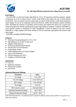
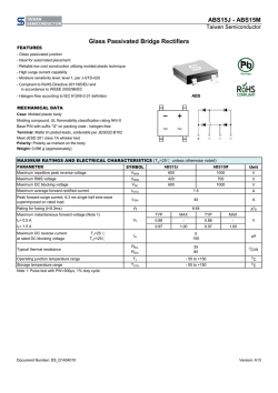
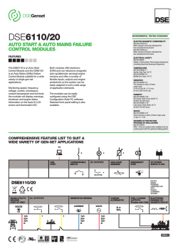
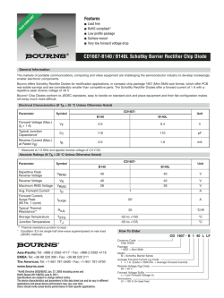
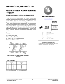
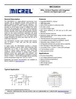
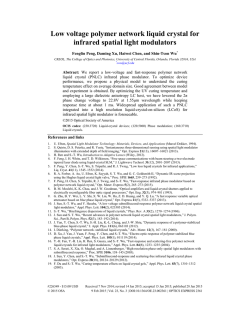
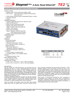
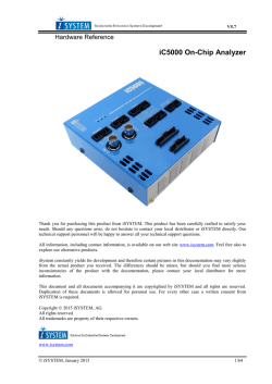
FMCW Transceiver RS3400W/04 Features: Complete 76-77GHz band FMCW Radar Front End Synthesized frequency source Wideband Sweep Description: The RS3400W/04 is a W-band FMCW radar front end featuring synthesized frequency sweeps. A fast sweep mode enables complete sweeps below 1ms. The system provides one Tx/Rx with a WR12 waveguide interface suitable for attaching compact high directivity antennas. Block Diagram: Bias RF I/O Frequency control Fractional N PLL RS3400W Integrity control RF output power control Analog IF output Balanced signal Data subject to change without notice. SPLT6254 RS3400W04 A.doc Sivers IMA AB Box 1274 SE-164 29 Kista Sweden Tel: +46-8-703 68 00 Fax: +46-8-751 92 71 e-mail: [email protected] www.siversima.com FMCW Transceiver RS3400W/04 Performance Specification: Estimated values. Tested or implicated by design. All units are tested at room temperature. Parameter RF: (Probing signal) Minimum output frequency Maximum output frequency Frequency stability1 Bandwidth stability Frequency setting resolution Frequency settling time2,3 IF: (Sensor output) Full reflection response amplitude4 Reflection response amplitude variation Min. Typ. Max. Unit 76000 35 35 MHz MHz ppm ppm kHz s 77000 200 40 4 6 4 12 5 dBVpp dB Min. Typ. Max. Unit 4 6 9 2 4 TBD TBD TBD dBm dB dB dBc dBc dBc dBc/Hz dB dBc W Typical values, not tested. Parameter RF output power RF output power variation (over frequency) RF output power variation (over temperature) Harmonics related to carrier Spurious (synthesizer related)5 Spurious (not synthesizer related) SSB phase noise @ 100 kHz from carrier RF to IF conversion efficiency6 Sensor dynamic range7 Power consumption8 -64 3 80 3.5 1 Over operating temperature range, input voltage variation, aging, shock, and vibration. Defined as time elapsed for a signal to settle within 0.1MHz of a 1 MHz frequency step. Settling time is strongly dependent on digital parameters settings of the FMCW module. 3 A synthesized, free running, mode is available enabling complete frequency sweep in times below 1 millisecond. 4 Defined as the IF output signal level (voltage peak-to-peak) when the complete RF (probing signal) is returned from a reflecting target. 5 Average over whole frequency band. 6 The IF signal power is measured as a voltage over 10k from the balanced IF port. This voltage is used to calculate a power assuming the voltage was dissipated in a 50 resistor. 7 Defined as signal level below full reflection response adjacent to detected peak in a Fourier transformed IF signal. 8 Power is delivered as +5.5V +- 0.1V, current consumption is typically 630mA. 2 Data subject to change without notice. SPLT6254 RS3400W04 A.doc Sivers IMA AB Box 1274 SE-164 29 Kista Sweden Tel: +46-8-703 68 00 Fax: +46-8-751 92 71 e-mail: [email protected] www.siversima.com FMCW Transceiver RS3400W/04 Interfaces and Electrical Specification: Connector /pin Pin Direction/ type DC connector Specification Single power supply Phoenix contact MKDSN2,5/2-5.08 or similar 5.5V ± 0.25V, approx. 650mA + POWER VDC, regulated voltage GND POWER Power ground 2x5 pole 0.1” lead spacing Control and IF signal RF I/O Description 1 2 3 4 5 6 7 8 9 10 N/A IN SIG GND IN SIG GND IN IN OUT SIG GND OUT OUT IN/OUT CLK GND DATA GND LATCH Power GO, active low IF+ GND IFPLL integrity control WR12 waveguide TE Connectivity PN 2-1761603-3 or similar Microwire 3.3V Digital ground Microwire 3.3V Digital ground Microwire 3.3V 0/3.3V 0-5.5V Analog ground 0-5.5V Open collector Compatible with UG-387/U flange Note on control and IF signal: Power GO: Controls output RF power. A low voltage (<1.0V) will enable full output power. A high voltage (>3.0V) will reduce output power by at least 20dB. PLL integrity control: Provides a low pass connection to the PLL MUX pin with which different signals can be tapped. Frequency lock can be reported as a test of integrity. IF+, IF-: Balanced IF output signal, short circuit protected. Output impedance is approximately 3k Programming of the RS3400W is done through a 3 wire interface. Please contact factory for details. Data subject to change without notice. SPLT6254 RS3400W04 A.doc Sivers IMA AB Box 1274 SE-164 29 Kista Sweden Tel: +46-8-703 68 00 Fax: +46-8-751 92 71 e-mail: [email protected] www.siversima.com FMCW Transceiver RS3400W/04 Environmental Specification: Parameter Operational temperature range9 Storage temperature range 9 Min. Max. Unit 0 -50 70 +100 C C Other temperature ranges available upon request. Mechanical drawing: Data subject to change without notice. SPLT6254 RS3400W04 A.doc Sivers IMA AB Box 1274 SE-164 29 Kista Sweden Tel: +46-8-703 68 00 Fax: +46-8-751 92 71 e-mail: [email protected] www.siversima.com


© Copyright 2026