
Stepnet Plus EtherCAT 2-Axis TE2
Stepnet Plus 2-Axis Panel EtherCAT TE2
RoHS
digital stepper drive for stepper motors
Control Modes
• Stepper mode:Cyclic Synchronous Position (CSP)
• Servo mode: Cyclic Synchronous Position/Velocity/Torque
(CSP, CSV, CST)
• Profile Position-Velocity-Torque, Interpolated Position, Homing
• Camming, Gearing
• Indexer
Command Interface
• CANopen application protocol over EtherCAT (CoE)
• ASCII and discrete I/O
• Master encoder (Gearing/Camming)
• Stepper mode position commands:
Digital: Pulse/Dir, CW/CCW, Quad A/B
Analog: ±10V position
• Servo mode commands:
Digital: Pulse/Dir, CW/CCW, Quad A/B
PWM velocity/torque command
Analog: ±10V position/velocity/torque
Communications
• EtherCAT
• RS-232
Feedback
Incremental Encoders
• Digital quad A/B
• Panasonic Incremental A Format
• Aux. quad A/B encoder / encoder out
Absolute Encoders
• SSI, EnDat, Absolute A,
Tamagawa & Panasonic Absolute A
Sanyo Denki Absolute A, BiSS (B & C)
I/O Digital
• 24 non-isolated, 8 isolated inputs,
• 5 isolated outputs, 2 non-isolated outputs
Analog
• 2 Reference Inputs, 12-bit
Safe Torque Off (STO)
• SIL 3, Category 3, PL d
Dimensions: IN [mm]
• 6.78 x 4.70 x 1.99 [172.1 x 119.3 x 50.4] no heatsink
• 6.78 x 4.70 x 3.14 [172.1 x 119.3 x 79.9] with heatsink
DESCRIPTION
The TE2 models are high-performance, DC powered drives for
pStepnet Plus TE2 is a 2-axis, high-performance DC powered
microstepping drive for control of hybrid stepping motors via
EtherCAT using the CAN Application Layer for EtherCAT (CoE).
Microstepping modes are Profile Position, Interpolated Position Mode
(PVT), and Homing. With encoder feedback, the TE2 can operate a stepper as a brushless servo motor, enabling Cyclic Sync Position/
Velocity/Torque operation, too.
As well as operating on EtherCAT networks, the TE2 also operates
in the following traditional control modes: step/direction, RS-232
ASCII, master encoder for gearing and camming, digital input
commands to initiate predetermined motion sequences.
There are sixteen non-isolated inputs and eight opto-isolated
digital inputs that are bipolar types, sourcing or sinking current
Copley Controls, 20 Dan Road, Canton, MA 02021, USA
Web: www.copleycontrols.com
Model
Ip
Ic
Vdc
TE2-090-07
7
5
90
TE2-090-10
10
10
90
Current ratings are for each axis
into a common connection that can be tied to ground or +24V.
[IN1&10] default to the drive Enable function for axes A & B,
and are programmable to other functions. The other inputs are
programmable. All inputs have programmable active levels. Five
opto-isolated outputs [OUT1~5] have individual collector/emitter
connections. Two MOSFET outputs [OUT6~7] are programmable
to drive motor brakes or other functions and have internal flyback
diodes for driving inductive loads.
Drive power is transformer-isolated DC from regulated or
unregulated power supplies. An AuxHV input is provided for
“keep-alive” operation permitting the drive power stage to be
completely powered down without losing position information, or
communications with the control system.
Tel: 781-828-8090 Fax: 781-828-6547
Page 1 of 30
Stepnet Plus 2-Axis Panel EtherCAT TE2
RoHS
general specifications
Test conditions: Load = Wye connected load: 2 mH + 2 Ω line-line. Ambient temperature = 25°C, +HV = HVmax
MODEL
TE2-090-06TE2-090-14
Output Power (each axis)
Peak Current
Peak time
Continuous current (Note 1)
INPUT POWER
HVmin~HVmax
Ipeak
Icont
Aux HV
7 (5)
1
5 (3.5)
10 (7.1)
1
10 (7.1)
+14 to +90
+14 to +90
14
20
10
20
+14 to +90 Vdc, 11 W max, 0.786 A @
DIGITAL CONTROL Digital Control Loops
Sampling rate (time)
Bus voltage compensation
Minimum load inductance
14 Vdc
Adc (Arms-sine), ±5%
Sec
Adc (Arms-sine) per phase
Vdc Transformer-isolated
Adc (1 sec) peak
Adc continuous
Optional, not required for operation
Current, velocity, position. 100% digital loop control
Current loop: 16 kHz (62.5 µs), Velocity & position loops: 4 kHz (250 µs)
Changes in bus or mains voltage do not affect bandwidth
200 µH line-line
command inputs (Note: Digital input functions are programmable)
Distributed Control Modes
CANopen application protocol over EtherCAT (CoE)
Cyclic Synchronous Position (CSP), Cyclic-sync Velocity/Torque (CSV, CST, servo mode),
Profile Position, Profile Velocity-torque (servo mode), Interpolated Position, Homing
Stand-alone mode
Analog position, velocity/torque(servo mode)
Dedicated differential analog input
±10 Vdc, 12-bit resolution
Digital position reference
Pulse/Direction, CW/CCW
Stepper commands (2 MHz maximum rate)
Quad A/B Encoder
2 M line/sec, 8 Mcount/sec (after quadrature)
Digital torque & velocity reference (servo mode)
PWM , Polarity
PWM = 0% - 100%, Polarity = 1/0
PWM 50%
PWM = 50% ±50%, no polarity signal required
PWM frequency range
1 kHz minimum, 100 kHz maximum
PWM minimum pulse width
220 ns
Up to 32 sequences can be launched from inputs or ASCII commands.
Indexing
Up to 10 CAM tables can be stored in flash memory
Camming
ASCII
RS-232, DTE, 9600~115,200 Baud, 3-wire, RJ-11 connector
digital inputs
Number 24
Digital, non-isolated, Schmitt trigger, 1.5 µs RC filter, 24 Vdc compatible, programmable 15k pull-up/down
[IN1,2,10,11]
to +5 Vdc/ground, Vt+ = 2.5~3.5 Vdc, VT- = 1.3~2.2 Vdc, VH = 0.7~1.5 Vdc
Digital, non-isolated, Schmitt trigger, 1.5 µs RC filter, 24 Vdc compatible, 15k pull-up to +5 Vdc/ground,
[IN19~21,22~24]
Vt+ = 2.5~3.5 Vdc, VT- = 1.3~2.2 Vdc, VH = 0.7~1.5 Vdc
[IN3,4,12,13]
Digital, non-isolated, programmable as single-ended or differential pairs, 100 ns RC filter, 12 Vdc max,
programmable pull-up/down per input to +5 Vdc/ground,
SE: Vin-LO ≤ 2.3 Vdc, Vin-HI ≥ 2.7 Vdc, VH = 45 mV typ, DIFF: Vin-LO ≤ 200 mVdc, Vin-HI ≥ 200 mVdc, VH = 45 mV typ
Digital, opto-isolated, single-ended, ±15~30 Vdc compatible, bi-polar, 2 groups of 4, each with a common terminal
[IN5~8,14~17]
Rated impulse ≥ 800 V, Vin-LO ≤ 6.0 Vdc, Vin-HI ≥ 10.0 Vdc, Input current ±3.6 mA @ ±24 Vdc, typical
Default as motor overtemp inputs on feedback connectors, 12 Vdc max, programmable to other functions
[IN9,18]
Other digital inputs are also programmable for the Motemp function
330 µs RC filter, 4.99k pullup to +5 Vdc, Vt+ = 2.5~3.5 Vdc, VT- = 1.3~2.2 Vdc, VH = 0.7~1.5 Vdc
Functions
All inputs are programmable, [IN1 & IN10] default to drive axes A & B Enable function and are programmable
analog inputs
Number2
[AIN1~2]
Differential, ±10 Vdc, 5 kW input impedance, 14-bit resolution
SAFE torque off (sto)
Function
Standard
Safety Integrity Level
Inputs
Type
Input current (typical)
Response time
Reference
PWM outputs active and current to the motor will not be possible when the STO function is asserted
Designed to IEC-61508-1, IEC-61508-2, IEC-61800-5-2, ISO-13849-1
SIL 3, Category 3, Performance level d
2 two-terminal: STO_IN1+,STO_IN1-, STO_IN2+, STO_IN2Opto-isolators, 24V compatible, Vin-LO ≤ 6.0 Vdc or open, Vin-HI ≥ 15.0 Vdc,
STO_IN1: 9.0 mA, STO_IN2: 4.5 mA
2 ms (IN1, IN2) from Vin ≤6.0 Vdc to interruption of energy supplied to motor
Complete information and specifications are in the Accelnet & Stepnet Plus Panels STO Manual
digital outputs
Number7
[OUT1~5]
Opto-isolated SSR, two-terminal, 300 mA max, 24 V tolerant, Rated impulse ≥ 800 V, series 1 Ω resistor
[OUT6~7]
Opto-isolated MOSFET, default as motor brake control, current-sinking,
1 Adc max, flyback diodes to +24 V external power supply for driving inductive loads
Programmable for other functions if not used for brake
RS-232 PORT
Signals
RxD, TxD, Gnd in 6-position, 4-contact RJ-11 style modular connector, non-isolated, common to Signal Ground
Mode
Full-duplex, DTE serial communication port for drive setup and control, 9,600 to 115,200 Baud
Protocol
Binary and ASCII formats
ethercat PORTS
Format
Dual RJ-45 receptacles, 100BASE-TX
Protocol
EtherCAT, CANopen application protocol over EtherCAT (CoE), CiA-402 for motion control devices
Notes:
1) Heatsink or forced-air required for continuous current rating
Copley Controls, 20 Dan Road, Canton, MA 02021, USA
Web: www.copleycontrols.com
Tel: 781-828-8090 Fax: 781-828-6547
Page 2 of 30
Stepnet Plus 2-Axis Panel EtherCAT TE2
RoHS
general specifications
dC power outputs
Number: Ratings
Connections
2: +5 Vdc, 500 mA max each output, thermal and short-circuit protected
Axis A: J1-17, J1-32, J7-6, J7-17; combined current from these pins cannot exceed 500 mA
Axis B: J1-23, J1-38, J8-6, J8-17; combined current from these pins cannot exceed 500 mA
indicators
AMP
Bicolor LED, drive state indicated by color, and blinking or non-blinking condition
RUN
Green LED, status of EtherCAT state-machine (ESM)
ERR
Red LED, shows errors due to time-outs, unsolicited state changes, or local errors
L/A
Green LED, Link/Act, shows the state of the physical link and activity on the link (EtherCAT connection)
RUN, ERR, and L/A LED colors and blink codes conform to ETG.1300 S(R) V1.1.0
protections
HV Overvoltage
+HV > 90 Vdc
Drive outputs turn off until +HV < 90 Vdc (See Input Power for HVmax)
Drive outputs turn off until +HV > +14 Vdc
HV Undervoltage
+HV < +14 Vdc
Drive outputs turn off
Drive over temperature
Heat plate > 70°C.
Short circuitsOutput to output, output to ground, internal PWM bridge faults
I2T Current limiting
Programmable: continuous current, peak current, peak time
Digital inputs programmable to detect motor temperature switch
Motor over temperature
Feedback Loss
Inadequate analog encoder amplitude or missing incremental encoder signals
MECHANICAL & ENVIRONMENTAL
Size IN [MM]
Weight LB[KG]
Ambient temperature
Humidity
Vibration
Shock
Contaminants
Environment
Cooling
6.78 x 4.70 x 1.99 [172.1 x 119.3 x 50.4] without heatsink
6.78 x 4.70 x 3.14 [172.1 x 119.3 x 79.9] with heatsink
1.5 [0.68] without heatsink, 2.75 [1.25] with heatsink
0 to +45C operating, -40 to +85C storage
0 to 95%, non-condensing
2 g peak, 10~500 Hz (sine), IEC60068-2-6
10 g, 10 ms, half-sine pulse, IEC60068-2-27
Pollution degree 2
IEC68-2: 1990
Heat sink and/or forced air cooling required for continuous power output
agency standards conformance (pending)
Approvals
UL and cUL recognized component to UL 61800-5-1 (file no. E168959)
TÜV SÜD Functional Safety to IEC 61508 and ISO 13849 <pending>
Functional Safety
IEC 61508-1, IEC 61508-2, EN (ISO ) 13849-1, EN (ISO) 13849-2, IEC 61800-5-2
(see The Stepnet & Stepnet Plus Panels STO Manual for further detail)
Electrical Safety
Directive 2006/95/EC – Low Voltage: IEC 61800-5-1:2007
UL 61800-5-1-2012
EMC
Directive 2004/108/EC – EMC:
IEC 61800-3:2004+A1:2011
Hazardous Substances
Directive 2011/65/EU (RoHS Directive)
Copley Controls, 20 Dan Road, Canton, MA 02021, USA
Web: www.copleycontrols.com
Tel: 781-828-8090 RoHS
Fax: 781-828-6547
Page 3 of 30
Stepnet Plus 2-Axis Panel EtherCAT TE2
RoHS
general specifications
feedback
Incremental:
Digital Incremental Encoder Quadrature signals, (A, /A, B, /B, X, /X), differential (X, /X Index signals not required)
5 MHz maximum line frequency (20 M counts/sec)
MAX3097 differential line receiver with 121 Ω terminating resistor between A & /A, B & /B inputs
X & /X inputs have 130 Ω terminating resistor, S & /S inputs have 221 Ω terminating resistor
X & S inputs have 1 kΩ pull-ups to +5V, /X & /X inputs have 1 kΩ pull-down to ground
Absolute:
EnDat
Serial data and clock signals (DATA, /DATA, CLK, /CLK), differential, 121 Ω inputs
Sin/cos signals (Sin+, Sin-, Cos+, Cos-)
Absolute A Tamagawa Absolute A, Panasonic Absolute A Format, Sanyo Denki Absolute A
SD+, SD- (S, /S) signals, 2.5 or 4 MHz, 2-wire half-duplex communication
Status data for encoder operating conditions and errors
multi-mode encoder port
As Input
As Emulated Output
As Buffered Output
Digital quadrature encoder (A, /A, B, /B, X, /X), 5 MHz maximum line frequency (20 M counts/sec),
MAX3097 line receiver, 1.5 kΩ pull-ups to +5V on X & S inputs, 1.5 kΩ pull-downs to Sgnd on /X & /S inputs
Digital absolute encoder (Clk, /Clk, Dat, /Dat) half or full-duplex operation,
S & X inputs are used for absolute encoder interface
Quadrature encoder emulation with programmable resolution to 4096 lines (65,536 counts) per rev
from analog sin/cos encoders, resolvers, or absolute encoders
A, /A, B, /B, from MAX3032 differential line driver, X, /X, S, /S from MAX3362 differential line driver
Digital A/B/X encoder feedback signals from primary quad encoder are buffered (see line drives above)
Copley Controls, 20 Dan Road, Canton, MA 02021, USA
Web: www.copleycontrols.com
Tel: 781-828-8090 Fax: 781-828-6547
Page 4 of 30
Stepnet Plus 2-Axis Panel EtherCAT TE2
RoHS
ethercat communications
EtherCAT is the open, real-time Ethernet network developed by
Beckhoff based on the widely used 100BASE-TX cabling system.
EtherCAT enables high-speed control of multiple axes while
maintaining tight synchronization of clocks in the nodes.
Data protocol is CANopen application protocol over EtherCAT (CoE)
based on DSP-402 for motion control devices.
More information on EtherCAT can be found on this web-site:
http://ethercat.org/default.htm
Ethercat connections
Dual RJ-45 sockets accept standard Ethernet cables. The IN port connects to a master, or to the OUT port of a device that is
‘upstream’, between the Stepnet and the master.
The OUT port connects to ‘downstream’ nodes.
If Stepnet is the last node on a network, only the IN port is used.
No terminator is required on the OUT port.
IN
EtherCAT LEDs (ON RJ-45 connectors)
RUN Green: Shows the state of the ESM (EtherCAT State Machine)
1
J3: EtherCAT PORTS
OUT
8
1
RJ-45 receptacles,
8 position, 4 signals
8
Pin
Off
= Init
Blinking
= Pre-operational
Err
L/A Run
L/A
Single-flash = Safe-operational
On
=Operational
ERR Red: Shows errors such as watchdog timeouts and unsolicited state changes in the TE2 due to local errors.
Off
= EtherCAT communications are working correctly
Blinking
= Invalid configuration, general configuration error
Single Flash = Local error, slave has changed EtherCAT state autonomously
Double Flash = PDO or EtherCAT watchdog timeout,or an application watchdog timeout has occurred
L/A Green: Shows the state of the physical link and activity on the link.
A green LED indicates the state of the EtherCAT network:
LED
Link
Activity
Condition
ON
Yes
No
Port Open
Flickering
Yes
Yes
Port Open with activity
Off
No
(N/A)
Port Closed
EtherCAT Device ID (station alias)
In an EtherCAT network, slaves are automatically assigned consecutive addresses
based on their position on the network. But when the device must have a positive
identification that is independent of cabling, a Device ID is used. In the TE2, this
is provided by two 16-position rotary switches with hexadecimal encoding. These
can set the Device ID of the drive from 0x00~0xFF (0~255 decimal). The chart
shows the decimal values of the hex settings of each switch.
Example 1: Find the switch settings for decimal Device ID 107:
1) Find the highest number in the x10 column that is less than 107 and
set x10 to the hex value in the same row:
96 < 107 and 112 > 107, so x10 = 96 = Hex 6
2) Subtract 96 from the desired Device ID to get the decimal value for the
switch x1 and set it to the Hex value in the same row:
x1 = (107 - 96) = 11 = Hex B
3) Result: X10 = 6, X1 = B, Alias = 0x6B (107)
signal
6
rx-
3
rx+
2
tx-
1
TX+
EtherCAT Device ID Switch
Decimal values
Set
x10
Hex
x1
Dec
Set
x10
x1
Hex
Dec
0
0
0
8
128
1
16
1
9
144
8
9
2
32
2
A
160
10
3
48
3
B
176
11
4
64
4
C
192
12
5
80
5
D
208
13
6
96
6
E
224
14
7
112
7
F
240
15
indicators: drive state
Two bi-color LEDs give the state of the TE2 drive. Colors do not alternate, and can be solid ON or
Copley Controls, 20 Dan Road, Canton, MA 02021, USA
Web: www.copleycontrols.com
Tel: 781-828-8090 AMP LEDs &
device id
switches
Plus
AMP
Stepnet
blinking. When multiple conditions occur, only the top-most condition will be displayed.
When that condition is cleared the next one TE2ow will shown.
1) Red/Blinking
= Latching fault. Operation will not resume until drive is Reset.
2) Red/Solid
= Transient fault condition. Drive will resume operation when
the condition causing the fault is removed.
3) Green/Double-Blinking = STO circuit active, drive outputs are Safe-Torque-Off
4) Green/Slow-Blinking
= Drive OK but NOT-enabled. Will run when enabled.
5) Green/Fast-Blinking
= Positive or Negative limit switch active.
Drive will only move in direction not inhibited by limit switch.
7) Green/Solid
= Drive OK and enabled. Will run in response to
reference inputs or EtherCAT commands.
Latching Faults
Defaults
Optional (programmable)
• Short circuit (Internal or external) • Over-voltage
• Drive over-temperature
• Under-voltage
• Motor over-temperature
• Motor Phasing Error
• Feedback Error
• Command Input Fault
• Following Error
J1
SIGNAL
S1
S2
X10
X1
ERR
DEV ID
Fax: 781-828-6547
Page 5 of 30
IN
L/A
RU
NETWOR
Stepnet Plus 2-Axis Panel EtherCAT TE2
RoHS
communications: rs-232 serial
TE2 is configured via a three-wire, full-duplex DTE RS-232 port
that operates from 9600 to 115,200 Baud, 8 bits, no parity,
and one stop bit. Signal format is full-duplex, 3-wire, DTE using
RxD, TxD, and Gnd. Connections to the TE2 RS-232 port are
through J4, an RJ-11 connector. The TE2 Serial Cable Kit (SERCK) contains a modular cable, and an adapter that connects to a
9-pin, Sub-D serial port connector (COM1, COM2, etc.) on PC’s
and compatibles.
After power-on, reset, or transmission of a Break character,
the Baud rate will be 9,600. Once communication has been
established at this speed, the Baud rate can be changed to a
higher rate (19,200, 57,600, 115,200).
RJ-11 receptacle,
6 position, 4 contact
1
5
Dsub-9F
to RJ11
Adapter
6
9
6
RJ-11 cable
6P6C
Straight-wired
D-Sub 9F
RxD
TxD
Gnd
2
5
3
2
5
3
TxD
RxD
Gnd
Pin
signal
1
J4: RS-232 Port
The SER-CK provides connectivity between a D-Sub 9 male connector and the RJ-11
connector on the TE2. It includes an adapter that plugs into the COM1 (or other) port
of a PC and uses common modular cable to connect to the TE2. The connections are
shown in the diagram TE2ow.
2
RxD
6
SER-CK serial cable kit
3,4
Gnd
5
Txd
1
RJ-11
on
Servo
Drive
Don’t forget to order a Serial Cable Kit SER-CK when placing your order for a TE2!
USB to RS-232 Adapters
These may or may not have the speed to work at the
115,200 Baud rate which gives the best results with
CME2. Users have reported that adapters using the
FTDI chipset work well with CME2
ASCII communications
The Copley ASCII Interface is a set of ASCII format commands that can be used to operate and monitor Copley Controls
Stepnet, Stepnet, and TE2 series amplifiers over an RS-232 serial connection. For instance, after basic amplifier configuration
values have been programmed using CME 2, a control program can use the ASCII Interface to:
• Enable the amplifier in Programmed Position mode.
• Home the axis.
• Issue a series of move commands while monitoring position, velocity, and other run-time variables.
The Baud rate defaults to 9,600 after power-on or reset and is programmable up to 115,200 thereafter.
After power-on, reset, or transmission of a Break character, the Baud rate will be 9,600. Once communication has been
established at this speed, the Baud rate can be changed to a higher rate (19,200, 57,600, 115,200).
ASCII parameter 0x90 holds the Baud rate data. To set the rate to 115,200 enter this line from a terminal:
s r0x90 115200 <enter>
Then, change the Baud rate in the computer/controller to the new number and communicate at that rate.
Additional information can be found in the ASCII Programmers Guide on the Copley website:
http://www.copleycontrols.com/Motion/pdf/ASCII_ProgrammersGuide.pdf
Copley Controls, 20 Dan Road, Canton, MA 02021, USA
Web: www.copleycontrols.com
Tel: 781-828-8090 Fax: 781-828-6547
Page 6 of 30
Stepnet Plus 2-Axis Panel EtherCAT TE2
RoHS
safe torque off (sto)
The Safe Torque Off (STO) function is defined in IEC 61800-5-2.
Two channels are provided which, when de-energized, prevent
the upper and lower devices in the PWM outputs from being
operated by the digital control core.
This provides a positive OFF capability that cannot be overridden
by the control firmware, or associated hardware components.
When the opto-couplers are energized (current is flowing in the
input diodes), the control core will be able to control the on/off
state of the PWM outputs.
installation
Refer to the Accelnet & Stepnet Plus Panels STO Manual
The information provided in the Accelnet & Stepnet Plus Panels STO Manual must be considered for
any application using the TE2 drive’s STO feature.
Failure to heed this warning can cause equipment damage, injury, or death.
DANGER
sto bypass (muting)
In order for the PWM outputs of the TE2 to be activated, current
must be flowing through all of the opto-couplers that are
connected to the STO-IN1 and STO-IN2 terminals of J6, and the
drive must be in an ENABLED state. When the opto-couplers are
OFF, the drive is in a Safe Torque Off (STO) state and the PWM outputs cannot be activated by the control core to drive a motor.
This diagram shows connections that will energize all of the optocouplers from an internal current-source. When this is done the
STO feature is overridden and control of the output PWM stage is
under control of the digital control core.
If not using the STO feature, these connections must be
made in order for the TE2 to be enabled.
sto bypass connections
functional diagram
Bypass Plug Connections
Jumper pins:
2-4, 3-5, 6-8, 7-9 *
V_in
Accelnet Plus Panel Dual-Axis
PWM Signals
1
6
3
4
5
6
7
*
8
9
1
safety connector J6
+VI
Buffer
5
+VI
2
* STO bypass connections on the TE2 and
Xenus XEL-XPL models are different. If both
drives are installed in the same cabinet, the
diode should be wired as shown to prevent
damage that could occur if the STO bypass
connectors are installed on the wrong drive.
The diode is not required for STO bypass
on the TE2 and can be replaced by a wire
between pins 7 and 9.
Voltage
Regulator
9
Current must flow
through all of the
opto-couplers
before the drive
can be enabled
EN
J6
Upper IGBT Gate Drive
STO-IN1+
+HV
STO-IN1PWM
Outputs
STO-IN2+
STO-IN2-
STO-IN1+
+VI
Lower IGBT Gate Drive
STO-IN1STO-Bypass (6.5 mA)
STO-Gnd (Sgnd)
Frame Ground
connections
SAFETY
Pin
Signal
Pin
Signal
1
Frame Gnd
6
STO-IN1+
2
STO-IN1+
7
STO-IN1-
1
6
9
5
3
STO-IN1-
8
STO-Bypass
4
STO-IN2+
9
STO-Gnd
5
STO-IN2-
Copley Controls, 20 Dan Road, Canton, MA 02021, USA
Web: www.copleycontrols.com
Tel: 781-828-8090 Fax: 781-828-6547
Page 7 of 30
Stepnet Plus 2-Axis Panel EtherCAT TE2
RoHS
digital command inputs: position
position command inputs
Single-ended digital position commands must be sourced from
devices with active pull-up and pull-down to take advantage of
the high-speed inputs.
For differential commands, the A & B channels of the multi-mode
encoder ports are used.
differential pulse & Direction
Single-ended pulse & Direction
[IN3(12)]
A
PULSE
/A
Inputs
Axis A(B)
Pulse
[IN4(13)]
/PULSE
B
DIRECTION
Direction
single-ended: IN3, 4, 12, 13
PULSE
DIRECTION
/B
/DIRECTION
Multi-port
Signal
Axis A
Axis B
[IN3(12)] Pls, CU, Enc A
J1-9
J1-14
[IN4(13)] Dir, CD, Enc B
J1-10
J1-15
Signal Ground
J1-6,16,22,31,
37,44
Frame Ground
J1-1
differential CU/CD CU (Count-Up)
Single-ended CU/CD
[IN3(12)]
A
Inputs
Axis A(B)
CU (CW)
[IN4(13)]
CU (CW)
/A
CD (Count-Down)
/CU (CW)
B
CD (CCW)
/B
CD (CCW)
/CD (CCW)
Multi-port
QUAD a/b ENCODER SINGLE-ENDED
[IN3(12)]
Inputs
Axis A(B)
QUAD a/b ENCODER DIFFERENTIAL
A
Encoder ph. A
/A
Enc. A
[IN4(13)]
Enc. B
B
Encoder ph. B
/B
differential: multi-port A, /A, B, /B
Signal
Axis A
Axis B
[Enc A] Pls, CU, Enc A
J1-36
J1-42
[Enc /A] /Pls, /CU, Enc /A
J1-21
J1-27
[Enc B] Dir, CD, Enc B
J1-35
J1-41
[Enc /B] /Dir, /CD, Enc /B
J1-20
J1-26
Signal Ground
J1-6,16,22,31,
37,44
Frame Ground
J1-1
Enc A
Enc /A
Enc B
Enc /B
Multi-port
digital command inputs: velocity, torque
Single-ended digital torque or velocity commands must be
sourced from devices with active pull-up and pull-down to take
advantage of the high-speed inputs.
Single-ended PWM & Direction
For differential commands, the A & B channels of the multi-mode
encoder ports are used.
A
Duty = 0 - 100%
[IN3(12)]
Axis A(B)
[IN4(13)]
single-ended: IN3, 4, 12, 13
differential PWM & Direction
/A
Curr-Vel
B
/B
[IN3(12)] Curr-Vel±
Axis A
Axis B
J1-9
J1-14
[IN4(13)] / Curr-Vel±
J1-10
J1-15
Pol-Dir
Signal Ground
J1-6,16,22,31,
37,44
/Pol-Dir
Frame Ground
J1-1
/Curr-Vel
Curr-Vel±
Pol-Dir
Signal
Multi-port
differential: multi-port A, /A, B, /B
Single-ended 50% PWM
Duty = 50% ±50%
<no connection>
differential 50% PWM
Axis A(B)
[IN3(12)]
[IN4(13)]
A
Duty = 50% ±50%
/A
Curr-Vel±
<not used>
<no connection>
Multi-port
Copley Controls, 20 Dan Road, Canton, MA 02021, USA
Web: www.copleycontrols.com
Curr-Vel±
/Curr-Vel±
Signal
Axis A
Axis B
[Enc A] Curr-Vel±
J1-36
J1-42
[Enc /A] /Curr-Vel±
J1-21
J1-27
[Enc B] Pol-Dir
J1-35
J1-41
[Enc /B] /Pol-Dir
J1-20
J1-26
Signal Ground
J1-6,16,22,31,
37,44
Frame Ground
J1-1
Tel: 781-828-8090 Fax: 781-828-6547
Page 8 of 30
Stepnet Plus 2-Axis Panel EtherCAT TE2
RoHS
multi-mode port as an input
input types
POSITION COMMAND INPUTS: DIFFERENTIAL
signals & pins
•Pulse & Direction
•CW & CCW (Clockwise & Counter-Clockwise)
•Encoder Quad A & B
•Camming Encoder A & B input
MAX3097
Input/Output
Select
A/B/X signals from
digital encoder
Axis A
J1
Axis B
J1
Pulse, CW, Encoder A
36
42
Signal
MAX3032
/Pulse, /CW, Encoder /A
21
27
Direction, CCW, Encoder B
35
41
/Direction, /CCW, Encoder /B
20
26
Quad Enc X, Absolute Clock
34
40
Quad Enc /X, /Absolute Clock
19
25
Enc S, Absolute (Clock) Data
33
39
18
24
Enc /S, / Absolute (Clock) Data
CURRENT or VELOCITY COMMAND INPUTS: DIFFERENTIAL
•Current or Velocity & Direction
•Current or Velocity (+) & Current or Velocity (-)
MAX3097
Frame Ground
1
J1 Multi-Port
Input/Output
Select
Pulse/Dir or CU/CD
differential commands
Signal Ground
6, 16, 22, 31, 37,
44
Frame Ground
A
MAX3032
Enc. A
/A
Incremental
Encoder
B
SECONDARY FEEDBACK: INCREMENTAL
•Quad A/B/X incremental encoder
MAX3097
A/B/X signals from
digital encoder
Enc. B
/B
X
Enc. X
/X
Input/Output
Select
MAX3032
Enc. X
Enc. X
SECONDARY FEEDBACK: ABSOLUTE
•S channel: Absolute A encoders (2-wire)
The S channel first sends a Clock signal and then
receives Data from the encoder in half-duplex mode.
•S & X channels: SSI, BiSS, EnDat encoders (4-wire)
The X channel sends the Clock signal to the encoder,
which initiates data transmission from the encoder
on the S-channel in full-duplex mode
2-Wire digital absolute
encoder signals
Input/Output
Select
4-Wire digital absolute
encoder signals
MAX3362
S
Enc. S
/S
Enc. S
MAX3362
S
S
Absolute
Encoder
S
Input
Select
+5V output @ 500 mA
Signal Ground
Output
Select
X
MAX3362
Copley Controls, 20 Dan Road, Canton, MA 02021, USA
Web: www.copleycontrols.com
Tel: 781-828-8090 Fax: 781-828-6547
Page 9 of 30
Stepnet Plus 2-Axis Panel EtherCAT TE2
RoHS
multi-mode port as an output
output types
buffered feedback outputs: DIFFERENTIAL
•Encoder Quad A, B, X channels
•Direct hardware connection between quad A/B/X
encoder feedback and differential line drivers for A/B/X outputs
emulated feedback outputs: DIFFERENTIAL
Firmware produces emulated quad A/B/X signals from feedback
data from the following devices:
•Absolute encoders
•Resolvers (-R option)
•Analog Sin/Cos incremental encoders
J1 Multi-Port
Frame Ground
A
B
Axis A
J1
Axis B
J1
Encoder A
36
42
Encoder /A
21
27
Encoder B
35
41
Encoder /B
20
26
Encoder X
34
40
Encoder /X
19
25
Encoder S
33
39
Encoder /S
18
24
Signal Ground
6, 16, 22, 31, 37, 44
Frame Ground
1
Enc. B
X
Enc. X
/X
Secondary
Encoder Input
Secondary
Encoder Input
MAX3097
MAX3097
Buffered A/B/X signals
from primary encoder
Incremental
Encoder
/B
signals & pins
Signal
Enc. A
/A
Input/Output
Select
Emulated A/B signals
MAX3362
MAX3032
Emulated Quad A/B
signals from
analog Sin/Cos encoder
Quad A/B/X primary
encoder
Copley Controls, 20 Dan Road, Canton, MA 02021, USA
Web: www.copleycontrols.com
Input/Output
Select
Tel: 781-828-8090 Fax: 781-828-6547
Page 10 of 30
Stepnet Plus 2-Axis Panel EtherCAT TE2
RoHS
CME2 defaults
These tables show the CME2 default settings. They are user-programmable and
the settings can be saved to non-volatile flash memory.
Axis A
Config
IN1
Enable-LO
IN2
IN3
IN4
PU/PD
Not
Configured
+5V
or
Sgnd
IN7
Config
*IN10
Enable-LO
*IN11
*IN12
*IN13
IN5
IN6
Axis B
Not
Configured
PU/PD
+5V
or
Sgnd
IN15
IN16
IN8
Axis B
Notes
OUT1
OUT2
Fault Active-OFF
OUT3
OUT4
Not Configured
OUT5
IN14
Opto
Not Configured
Axis A
OUT6
OUT7
Brake Active-HI
Notes
Opto
Not Configured
IN17
IN9
Motemp
IN18
Motemp
IN19
J7-2
IN22
J8-2
IN20
J7-3
IN23
J8-3
IN21
J7-4
IN24
J8-4
+5V
+5V
Axes A, B
Notes
Axis A
Axis B
Analog: Reference Filter
Disabled
√
√
Vloop: Input Filter
Disabled
√
√
Amp Over Temp
Vloop: Output Filter 1
Low Pass, Butterworth,
2-pole, 200 Hz
√
√
Motor Over Temp
Vloop: Output Filter 2
Disabled
Vloop: Output Filter 3
Disabled
Iloop: Input Filter 1
Disabled
Motor Wiring
Disconnected
Iloop: Input Filter 2
Disabled
STO Active
Input Shaping
Disabled
Short Circuit
Over Voltage
Under Voltage
Optional Faults
Over Current (Latched)
Axes A, B
Notes
Method
Set Current Position as Home
Copley Controls, 20 Dan Road, Canton, MA 02021, USA
Web: www.copleycontrols.com
Tel: 781-828-8090 Fax: 781-828-6547
Page 11 of 30
Stepnet Plus 2-Axis Panel EtherCAT TE2
RoHS
high speed inputs: in1, IN2, in10, in11, IN19, IN20, IN21, IN22, IN23, IN24
• Digital, non-isolated, high-speed
• Programmable pull-up/pull-down: IN1, IN2, IN10, IN11
Fixed pull-up to +5V: IN19, IN20, IN21, IN22, IN23, IN24
• 24V Compatible
connections
• Programmable functions
specifications
Input
Input Voltages
Pull-up/down
Low pass filter
Input Current
Time constant
Data
Notes
HI
VT+ = 2.5~3.5 Vdc
LO
VT- = 1.3~2.2 Vdc
VH1
VH = ±0.7~1.5 Vdc
Max
+30 Vdc
Min
0 Vdc
R1
15 kW
R2
15 kW
C1
100 pF
24V
-0.33 mAdc
RC
1.5 µs
2
Pin
Input
Pin
IN1
J1-7
IN19
J7-2
IN2
J1-8
IN20
J7-3
IN10
J1-12
IN21
J7-4
IN11
J1-13
IN22
J8-2
IN23
J8-3
Sgnd
J1:
6, 16,
22, 31,
37, 44
IN24
J8-4
Sgnd
J7, J8:
5, 16,
25, 26
+5V PullUp = +5V
PullDown = 0V
R1
74HC14
R2
[INx]
C1
Notes:
1) VH is hysteresis voltage
(VT+) - (VT-)
2) The R2*C2 time constant applies when input is driven by
active HI/LO devices
1.3 mAdc
0V
Input
single-ended/differential inputs: in3, in4, in12, in13
single-ended
Digital, non-isolated, high-speed
Progammable pull-up/pull-down
12V Compatible
Single-ended or Differential
Programmable functions
12V
Input Voltages
Differential3
Common mode
Pull-up/down
Low pass filter
Time constant
MAX3096
R2
[IN3,12]
Data
C1
Notes
HI
Vin ≥ 2.7 Vdc
LO
Vin ≤ 2.3 Vdc
VH
45 mVdc typ
1
HI
2.5V
R1
R2
Vdiff ≥ +200 mVdc
LO
Vdiff ≤ -200 mVdc
VH
±45 mVdc typ
Vcm
0 to +12 Vdc
R1
10 kW
R2
1 kW
C1
100 pF
RC2
100 ns
Notes:
1) VH is hysteresis voltage
IN2 - IN3 or IN12 - IN13
2) The R2*C2 time constant
applies when input is driven by
active HI/LO devices)
3) Vdiff = AINn(+) - AINn(-)
n = 1 for Axis A, 2 for Axis B
+
+5V
[IN4,13]
C1
MAX3096
differential
12V
J1 Control
+5V
+
Input Voltages
Single-ended
+5V
R1
specifications
Input
J1 Control
+
•
•
•
•
•
R1
[IN3,12]
connections
S.E.
Diff
IN3
C1
Pin
IN3+
J1-9
IN4
IN3-
J1-10
IN12
IN12+
J1-14
IN13
IN12-
J1-15
Sgnd
MAX3096
R2
+5V
R1
[IN4,13]
J1-6, 16, 22, 31, 37 , 44
Copley Controls, 20 Dan Road, Canton, MA 02021, USA
Web: www.copleycontrols.com
R2
Tel: 781-828-8090 C1
Fax: 781-828-6547
Page 12 of 30
Stepnet Plus 2-Axis Panel EtherCAT TE2
RoHS
motor overtemp inputs: in9, in18
•
•
•
•
Digital, non-isolated
Motor overtemp inputs
12V Compatible
Programmable functions
motor over temp input
The 4.99k pull-up resistor works with PTC
(positive temperature coefficient) thermistors
that conform to BS 4999:Part 111:1987, or
switches that open/close indicating a motor
over-temperature condition. The active level is
programmable.
specifications
Input
Data
Input Voltages
Pull-up/down
Input Current
Low pass filter
Time constant
J7,J8
Notes
HI
Vin ≥ 3.5 Vdc
LO
Vin ≤ 0.7 Vdc
Max
+12 Vdc
Min
0 Vdc
R1
4.99 kW
12V
1.4 mAdc
0V
-1.0 mAdc
R2
10 kW
C1
33 nF
Te
330 µs *
* RC time constant applies
when inputs are driven by
active high/low devices
+5V
R1
[IN9(18)]
Thermistor,
Posistor,
or switch
R2
C1
Signal Gnd
BS 4999:Part 111:1987
Ohms
Property
Resistance in the temperature
range 20°C to +70°C
connections
Input
Pin
IN9
J7-7
IN18
J8-7
Sgnd
J7,8-5, 16, 25, 26
Resistance at 85°C
60~750
≤1650
Resistance at 95°C
≥3990
Resistance at 105°C
≥12000
opto-isolated inputs: in5, in6, IN7, IN8, IN14, in15, in16, in17
•
•
•
•
•
Digital, opto-isolated
2 Groups of four, each with own Common terminal
Works with current sourcing or sinking drivers
24V Compatible
Programmable functions
24V
GND
24V
+
specifications
Input
Data
Input Voltages
Input Current
[ICOM1(2)]
[IN5(14)]
Notes
HI
Vin ≥ ±10.0 Vdc *
LO
Vin ≤ ±6 Vdc *
Max
±30 Vdc *
±24V
±3.6 mAdc
0V
J2
4.99k
[IN6(15)]
4.99k
4.7k
5.1V
4.7k
5.1V
0 mAdc
* Vdc Referenced to ICOM terminals.
[IN7(16)]
connections
4.99k
Signal
Pins
Signal
Pins
IN5
J2-2
IN14
J2-7
IN6
J2-3
IN15
J2-8
IN7
J2-4
IN16
J2-9
IN8
J2-5
IN17
J2-18
ICOM1
J2-6
ICOM2
J2-17
Copley Controls, 20 Dan Road, Canton, MA 02021, USA
Web: www.copleycontrols.com
[IN8(17)]
+
24V
Tel: 781-828-8090 4.99k
4.7k
5.1V
4.7k
5.1V
Fax: 781-828-6547
Page 13 of 30
Stepnet Plus 2-Axis Panel EtherCAT TE2
RoHS
analog inputs: ain1, ain2
• ±10 Vdc, differential
• 12-bit resolution
• Programmable functions
The analog inputs have a ±10 Vdc range at 12-bit resolution
As reference inputs they can take position/velocity/torque
commands from a controller. If not used as command inputs,
they can be used as general-purpose analog inputs.
specifications
Spec
Data
Notes
Input Voltage
Vref
±10 Vdc
Input Resistance
Rin
5.05 kW
J1
D/A
F.G.
Shield (Frame Gnd)
AINn(+)
±10V
Pins
Signal
AIN(+)
AIN(-)
Sgnd
Vref
AINn(-)
connections
+
Sgnd
Axis A
Axis B
J1-3
J1-5
J1-2
J1-4
1.5V
J1-6, 16, 22, 31, 37, 44
opto-isolated outputs: out1, out2, out3, out4, out5
•
•
•
•
•
Digital, opto-isolated
MOSFET output SSR, 2-terminal
Flyback diodes for inductive loads
24V Compatible
Programmable functions
J2
SSR
[OUTn+]
specifications
80Ω
min*
1
Output
Data
Notes
ON Voltage
OUT(+) - OUT(-)
Vdc
0.85V @ 300 mAdc
Output Current
Iout
300 mAdc max
+
Vdc
36V
[OUTn-]
300mA
max
* at 24 Vdc
HI/LO definitions: outputs
Input
OUT1~5
connections
Signal
(+)
(-)
OUT1
J2-19
J2-10
OUT2
J2-20
J2-11
OUT3
J2-21
J2-12
OUT4
J2-22
J2-13
OUT5
J2-23
J2-14
Copley Controls, 20 Dan Road, Canton, MA 02021, USA
Web: www.copleycontrols.com
State
Condition
HI
Output SSR is ON, current flows
LO
Output SSR is OFF, no current flows
Tel: 781-828-8090 Fax: 781-828-6547
Page 14 of 30
Stepnet Plus 2-Axis Panel EtherCAT TE2
RoHS
opto-isolated motor brake outputs: out6, out7
•
•
•
•
•
•
Brake outputs
Opto-isolated
Flyback diodes for inductive loads
24V Compatible
Connection for external 24V power supply
Programmable functions
J3
5
Brk 24V Input
4
Brk 24V Output
specifications
Output
Data
Notes
Voltage Range
Max
+30 Vdc
Output Current
Ids
1.0 Adc
3
Brake A
HI/LO definitions: outputs
Input
State
Condition
Output transistor is OFF
Brake is un-powered and locks motor
Motor cannot move
Brake state is Active
HI
BRK-A,B
OUT6,7
Brake B
Output transistor is ON
Brake is powered, releasing motor
Motor is free to move
Brake state is NOT-Active
LO
+Aux
0V
3
+HV
2
0V
1
6
J1
Control
16
22
31
37
44
1
J5
Serial
3
4
J9
Mot A
J10
Mot B
1
1
0
24V Return
i
J2
I/O
The brake circuits are optically isolated from
all drive circuits and frame ground.
connections
Pin
J3
Brake
1
Frame
Gnd
HV Com
5
Brk 24V Input
4
Brk 24V Output
Signal Gnd
Signal Gnd
3
Signal Gnd
Brake A
Signal Gnd
Signal Gnd
Signal Gnd
24V
2
Frame Gnd
Brake B
Signal Gnd
1
Signal Gnd
Heatplate/chassis
+
1
CME2 Default Setting for Brake Outputs [OUT6,7] is “Brake - Active HI”
Active =Brake is holding motor shaft (i.e. the Brake is Active)
Motor cannot move
No current flows in coil of brake
CME2 I/O Line States shows Output 6 or 7 as HI
BRK Output voltage is HI (24V), MOSFET is OFF
Stepper drive output current is zero
Stepper drive is disabled, PWM outputs are off
Inactive =
Brake is not holding motor shaft (i.e. the Brake is
Inactive)
Motor can move
Current flows in coil of brake
CME2 I/O Line States shows Output 6 or 7 as LO
BRK output voltage is LO (~0V), MOSFET is ON
Stepper drive is enabled, PWM outputs are on
Stepper drive output current is flowing
J11
Power
24V
2
Signal
5
Brk 24V Input
4
Brk 24V Output
3
Brake A [OUT6]
2
Brake B [OUT7]
1
24V Return
This diagram shows the
connections to the drive that
share a common ground in
the driver. If the brake 24V
power supply is separate
from the DC supply powering
the drive, it is important
that it connects to an earth
or common grounding point
with the HV power supply.
+
0
24V Return
i
Earth Ground
Earthing connections for power supplies should be as close as possible to elimimate
potential differences between power supply 0V terminals.
Copley Controls, 20 Dan Road, Canton, MA 02021, USA
Web: www.copleycontrols.com
Tel: 781-828-8090 Fax: 781-828-6547
Page 15 of 30
Stepnet Plus 2-Axis Panel EtherCAT TE2
RoHS
feedback connections
quad a/b/X ENCODER with signal loss detection
Encoders with differential line-driver
outputs are required (single-ended
encoders are not supported) and provide
incremental position feedback via the A/B
signals and the optional index signal (X)
gives a once per revolution position mark.
The MAX3097 receiver has differential
inputs with fault protections for the
following conditions:
ConditionExample
Line-line shorts A shorted to /A
Open-circuits: A disconnected, /A connected. Terminator resistor pulls
A & /A together for a short-circuit fault
Low-voltage
Va - Vb ≤ 200 mV, or ≥ -200 mV
Encoder power loss, cabling, etc.
signal loss detection logic
Encoder Loss Detection Logic
A
Va -++-
quad encoder with index
Encoder
FG
J7,J8
A/B/X Signals
Signal
J7,J8 Pin
Enc A
13
Enc. A
Enc /A
12
Enc B
11
Enc. B
Enc /B
10
Frame Ground
A
A
/A
121
B
B
/B
121
1k
X
Z
/X
+5V
0V
Enc. Index
130
1k
+5V Out @ 500 mA
Signal Ground
+5V
Enc X
9
Enc /X
8
+5V
6, 17
Sgnd
5, 16, 25, 26
F.G.
1
B
Vb -++-
Encoder-Loss
B
Fault
/B
X
Vx -++-
A
Fault
/A
X
Fault
Index-Loss
/X
CME2 Feedback options
Sgnd = Signal Ground
F.G. = Frame Gnd
Copley Controls, 20 Dan Road, Canton, MA 02021, USA
Web: www.copleycontrols.com
Tel: 781-828-8090 Fax: 781-828-6547
Page 16 of 30
Stepnet Plus 2-Axis Panel EtherCAT TE2
RoHS
feedback connections
endat absolute Encoder
The EnDat interface is a Heidenhain interface that is similar to
SSI in the use of clock and data signals, but which also supports
analog sin/cos channels from the same encoder. The number
of position data bits is programmable as is the use of sin/cos
channels. Use of sin/cos incremental signals is optional in the
EnDat specification.
Encoder
FG
1k
+5V
Clk
Clk
1k
Clk
B
1k
Dat
Data
A
130
/Clk
+5V
A
Data
221
/Dat
B
1k
Sin(+)
sin
Sin(-)
10k
cos
Cos(-)
10k
0V
Sin
+
-
Cos
121
10k
+5V
-
121
10k
Cos(+)
The Absolute A interface is a serial, half-duplex type
that is electrically the same as RS-485. Note the battery
which must be connected. Without it, the encoder will
produce a fault condition.
Absolute-A
Encoder
endat
Signals
J7,J8
Frame
Ground
Absolute-a Encoder
+
+5V Out @ 500 mA
J7,J8
5V
5V
1k
1.2k
Dat
SD+
Signal
J7, J8 Pin
Clk
9
/Clk
8
Data
15
/Data
14
Sin(+)
19
Sin(-)
18
Cos(+)
21
Cos(-)
20
+5V
6, 17
Signal
J7,J8 Pin
5, 16, 25, 26
Data
15
1
/Data
14
Sgnd
F.G.
Sgnd = Signal Ground
F.G. = Frame Gnd
Signal Ground
SD
220
SD-
D-R
/Dat
1.2k
Batt+
Cmd
Batt-
MAX3362B
V+
V-
221
Cmd
1k
D-R
+
SD
-
+5V Out
@ 500 mA
+5V
0V
Signal Ground
Battery
absolute-a
Signals
+5V
6, 17
Sgnd
5, 16, 25, 26
F.G.
1
Sgnd = Signal Ground
F.G. = Frame Gnd
Copley Controls, 20 Dan Road, Canton, MA 02021, USA
Web: www.copleycontrols.com
Tel: 781-828-8090 Fax: 781-828-6547
Page 17 of 30
Stepnet Plus 2-Axis Panel EtherCAT TE2
RoHS
motor connections
motor phase connections
The drive outputs are two H-bridge PWM inverters that convert the DC buss voltage
(+HV) into sinusoidal voltage waveforms
that drive the motor phase-coils. Cable
should be sized for the continuous current
rating of the drive. Motor cabling should
use twisted, shielded conductors for CE
compliance, and to minimize PWM noise
coupling into other circuits. Further details
on motor connections can be found on
page 22.
J9, J10
PWM
motor Signals
Signal
J9,J10 Pin
Mot A
5
Mot /A
4
Mot B
3
Mot /B
2
Frame Gnd
1
MOT /A
+HV
+
Signal
Pin
J7-7
Motemp B
J8-7
J7,J8
Signal Ground
5,10
Frame Gnd
12
MOT /B
Frame Gnd
Gn/Y
J7,J8
The 4.99k pull-up resistor works with PTC (positive temperature
coefficient) thermistors that conform to BS 4999:Part 111:1987
(table TE2ow), or switches that open/close indicating a motor
over-temperature condition. The active level is programmable.
These inputs are programmable for other functions if not used
as Motemp inputs. And, other inputs are programmable for the
Motemp function.
Motemp A
Stepper
Motor
2 ph.
MOT B
0V
motor over temp input
motemp Signals
MOT A
+5V
R1
[IN9(18)]
Thermistor,
Posistor,
or switch
R2
C1
Signal Gnd
BS 4999 SENSOR
Property
Resistance in the temperature range
20°C to +70°C
Resistance at 85°C
Resistance at 95°C
Resistance at 105°C
Copley Controls, 20 Dan Road, Canton, MA 02021, USA
Web: www.copleycontrols.com
Ohms
60~750
≤1650
≥3990
≥12000
Tel: 781-828-8090 Fax: 781-828-6547
Page 18 of 30
Stepnet Plus 2-Axis Panel EtherCAT TE2
RoHS
motor connections: digital quad a/b encoder
The connections shown may not be used in all installations
Stepnet Plus Panel 2-Axis
Frame Gnd
1
A
Enc A 13
/A
Enc /A 12
B
Enc B 11
/B
Enc /B 10
J7
J8
Enc X
9
Enc /X
8
DIGITAL
ENCODER
X
/X
Vcc
+5V Out 6 17
Signal
Gnd 5 25
0V
26
[IN19,22] 18
2
[IN20,23]
3
6
[IN21,24] 19
Note:
[IN19~21] are on J7
[IN22~24] are on J8
4
Signal Gnd 16
Motemp
TEMP
SENSOR
7
Brk 24V Input 5
+
Brk 24V Output 4
J3
Brake A 3
Brake B 2
24 Vdc
Brk
Brk
0V
24V Return 1
J9
J10
Mot A
5
Mot /A
4
Mot B
3
Mot /B
2
Frame Gnd
1
A
/A
B
STEPPER
MOTOR
/B
Grounding
tab
Notes:
1) The +5VOut1 on J1-17,32 and J7-6, 17 is rated for 500 mA
The +5VOut2 on J1-23,38 and J8-6, 17 is rated for 500 mA
These are two independent power supplies, each with a 500 mA max output from all pins
2) CE symbols indicate connections required for CE compliance.
Copley Controls, 20 Dan Road, Canton, MA 02021, USA
Web: www.copleycontrols.com
Tel: 781-828-8090 Fax: 781-828-6547
Page 19 of 30
Stepnet Plus 2-Axis Panel EtherCAT TE2
RoHS
device structure & isolation
This graphic shows the electrical structure of the drive, detailing the elements that share a common circuit
common (Signal Ground, HV Com) and circuits that are isolated and have no connection to internal circuits.
Note that there is no connection between the heatplate (Chassis, Frame Ground) and any drive circuits.
J11 HV & Aux
+
1
+HV
5
1360 µF
+
+HV
2
-
J9 Axis A
4
PWM
Inverter
Axis A
Motor
3
2
HV Com
1
Earth
Ground
Frame Gnd
DC-DC
Converter
3 Aux
5
4
J5 Serial
3
2
Internal DC
Power for
All Circuits
TxD
Sgnd
Motor cable shield
connects to Frame Ground
HV Com
Gnd
5
4
PWM
Inverter
Sgnd
Signal Gnd
J10 Axis B
Axis B
Motor
3
2
RxD
1
Frame Gnd
Tx1+
J4 EtherCAT
X2 In and Out
Ports are Identical
Motor cable shield
connects to Frame Ground
75
Tx1-
Control Core circuits are
referenced to Signal
Ground (Sgnd)
and HV Com ground
1M
Isolated
EtherCAT
Connections are
isolated from
drive circuits
10n
Rx1+
Brk 24V Input
Isolated
Brk 24V Output
+
R-L
75
Rx1-
+24V
Brake A
-
R-L
Brake B
Vcc
Vcc
24V Return
[IN1~4, 10~13]
[IN9,18, IN19~24]
J3 Brake
Sgnd
Vcc
Sgnd
J1 Control
Vcc
J7,J8 Axes A,B
Motor temp switch
[IN5~8,14~17]
Vcc
Sgnd
Isolated
[IN9,18]
[OUT1~5+]
Vcc
[AIN1~2+/-]
-
Sgnd
J2 I/O
+
[OUT1~5-]
Sgnd
DRIVE CIRCUITS
BE2 Heatplate
Copley Controls, 20 Dan Road, Canton, MA 02021, USA
Web: www.copleycontrols.com
Earth
Ground
HEATPLATE
Tel: 781-828-8090 Fax: 781-828-6547
Page 20 of 30
Stepnet Plus 2-Axis Panel EtherCAT TE2
RoHS
power & grounding connections
DC Power Connections
• DC power must be provided by transformers that are galvanically isolated and provide reinforced insulation from the mains.
Auto-transformers cannot be used.
• The (-) terminal of the power supply is not grounded at the power supply. It is grounded near each drive.
• Cabling to multiple drives for the +HV and 0V is best done in a “star” configuration, and not a “daisy-chain”.
• The 0V, or return terminal of the DC power should be connected to frame ground near the drive power connector.
From that point, a short wire can connect to the drive HV Ground.
• Cabling to the drive +HV and 0V terminals must be sized to carry the expected continuous current of the drive in the user’s
installation.
• DC power cabling should be shielded, twisted-pair for best EMI reduction. The shield should connect to the power supply frame
ground on one end, and to the drive frame ground on the other. Adding a pigtail and ring-lug, as short as possible will provide a
good connection of the shield at the drive.
• Motor cabling typically includes a green/yellow conductor for protective bonding of the motor frame.
Connect as shown in the Motor Connections diagram on the following page.
• Motor cable conductors should be twisted and shielded for best EMI suppression.
• If a green/yellow grounding wire connects the motor to the drive’s PE terminal, the shield pigtail and ring-lug may connect to one
of the screws that mount the drive to the panel. A P-clip to ground the shield as near as possible to the drive will increase the EMI
suppression of the shield. On the motor-end, the shield frequently connects to the connector shell. If the motor cable is a flyinglead from the motor, the shield may be connected to the motor frame internally.
• Braided cable shields are more effective for EMI reduction than foil shields. Double-shielded cables typically have a braided outer
shield and foil shields for the internal twisted pairs. This combination is effective for both EMI reduction and signal quality of the
feedback signals from analog encoders or resolvers.
• Motor cable shielding is not intended to be a protective bonding conductor unless otherwise specified by the motor manufacturer.
• For feedback cables, double-shielded cable with a single outer shield and individual shielded twisted pair internal shields gives the
best results with resolvers, or analog sin/cos encoders.
• In double-shielded cables, the internal shielding should connect to the drive’s Signal Ground on one end, and should be
unconnected on the motor end.
• Single-shield feedback cables connect to the drive frame on one end, and to the motor frame on the other.
Depending on the construction of the motor, leaving the feedback cable shield disconnected on the motor but connected on the
drive end may give better results.
• The drive should be secured to the equipment frame or panels using the mounting slots. This ensures a good electrical connection
for optimal EMI performance. The drive chassis is electrically conductive.
DC Power wiring
P-clips secure cables to a panel and provide full contact to the cable shields after the insulation has been
stripped. This should be done as close to the drive as possible for best EMI attenuation.
Aux
HV
+
-
3
Line
Filter
AC
Mains
H
~
~
N
~
~
2
+
+
Plus Panels
Drive
Aux
+HV
+
-
1
--
HV
Ground
Gnd
Green/Yellow
Unregulated
Power Supply
Earth
Ground
Frame
Ground
P-Clip
Power
Connector
1-Axis = J7
2-Axis = J10
Equipment Ground
Copley Controls, 20 Dan Road, Canton, MA 02021, USA
Web: www.copleycontrols.com
Tel: 781-828-8090 Fax: 781-828-6547
Page 21 of 30
Stepnet Plus 2-Axis Panel EtherCAT TE2
RoHS
+HV Power Supply Requirements
Regulated Power Supplies
• Must be over-voltage protected to 100 Vdc max when the STO (Safe Torque Off)
feature of the drive is used.
• Require a diode and external capacitor to absorb regenerative energy.
• The VA rating should be greater than the actual continuous output power of the
drives connected to the power supply, and adequate for the transient output
power due to acceleration of motor loads.
• Must handle the internal capacitance of the drives on startup.
Unregulated Power Supplies
• No-load, high-line output voltage must not exceed 90 Vdc.
• Power supply internal capacitance adds to the drive’s internal capacitance
for absorption of regenerative energy.
• The VA (Volts & Amps) rating at the power supply’s AC input is typically 30~40%
greater than the total output power of the drives.
Regulated (+)
Power
Supply
(-)
Cext
Cext: External
Unregulated
Power
Supply
+
Cint
(+)
+
+
Cps
Drive
Cint: Internal
Capacitor
Capacitor
AUXILIARY HV POWER
• Aux HV is power that can keep the drive communications and feedback circuits active
when the PWM output stage has been disabled by removing the main +HV supply.
• Useful during EMO (Emergency Off) conditions where the +HV supply must be
removed from the drive and powered-down to ensure operator safety.
• Voltage range is the same as +HV.
• Powers the DC/DC converter that supplies operating voltages to the drive DSP and
control circuits.
• Aux HV draws no current when the +HV voltage is greater than the Aux HV voltage.
Motor connections
• Motor cable shield connects to motor frame,
is grounded with a P-clip near the drive and
terminates in a ring-lug that is screwed to
the drive chassis by a mounting screw to the
panel
• If provided, a green/yellow grounding wire
from the motor connects to the F.G. terminal
of the motor connector.
feedback connections
• Cable shield connects to motor frame and to
the F.G. terminal of the feedback connector.
• When double-shielding is used, the inner
shields connect to the Signal Ground at the
drive, and is not connected at the motor end.
• If not provided by the motor manufacturer,
feedback cables rated for RS-422
communications are recommended for digital
encoders.
+
Drive
Cint
(-)
Cps: Power Supply
Cint: Internal
Capacitor
Capacitor
Feedback
Enc A {
Enc B {
Encoder
Enc X {
Sgnd
Inner Shields
Outer Shield
F.G.
Motor
A
/A
Motor
B
/B
F.G.
Earth
Ground
P-clip
Frame
Ground
energy
absorption
REGENERATION
2.0
1.8
Joules (W·s)
This chart shows the energy absorption in
W·s for the drive operating at some typical
DC voltages. It is based on the internal 470
uF capacitor and would be increased by the
capacitance of the external DC power supply.
When the load mechanical energy is greater
than these values an external regenerative
energy dissipater is required, or the DC power
supply capacitance can be increased to absorb
the regen energy.
1.6
1.4
1.2
1.0
0.8
0.6
0.4
0.2
0.0
Copley Controls, 20 Dan Road, Canton, MA 02021, USA
Web: www.copleycontrols.com
25
30
40
50
60
70
80
90
Tel: 781-828-8090 Fax: 781-828-6547
Page 22 of 30
Stepnet Plus 2-Axis Panel EtherCAT TE2
RoHS
connectors & signals: front panel
J6 safety (SAFEtorque off)
Pin
Signal
Pin
Signal
1
Frame Gnd
6
STO-IN1+
2
STO-IN1+
7
STO-IN1-
1
6
J6 TE2 Connector:
Dsub DE-09F, 9 position female receptacle
J6 Cable Connector:
3
STO-IN1-
8
STO-Bypass
4
STO-IN2+
9
STO-Gnd
5
STO-IN2-
5
9
Dsub DE-09M, 9 position
Details on J1, J2, J6, J7, and J8 cable
connectors can be found in the TE2-CK
listing under the Accessories section of
the last page
J2: isolated control
Pin
Signal
[IN17] GPI
26
n.c.
8
[IN15] GPI
17
COM2 [IN14~17]
25
n.c.
7
[IN14] GPI
16
N/C
24
n.c.
9
6
COM1 [IN5~8]
15
N/C
23
[OUT5+] GPI
5
[IN8] GPI
14
[OUT5-] GPI
22
[OUT4+] GPI
4
[IN7] GPI
13
[OUT4-] GPI
21
[OUT3+] GPI
3
[IN6] GPI
12
[OUT3-] GPI
20
[OUT2+] GPI
2
[IN5] GPI
11
[OUT2-] GPI
19
[OUT1+] GPI
1
Frame Ground
10
[OUT1-] GPI
1
J2: TE2 Connector
High-Density Dsub DA-26M, male plug, 26 Position
18 26
10
J6 SAFETY
Signal
18
19
J2: Cable Connector
J2 I/O
High-Density Dsub DA-26F, female receptacle, 26 Position
J1: Control Signals
Signal
Pin
31
Signal
1
Frame Gnd
16
Signal Gnd
Signal Gnd
2
[AIN1-]
17
A +5Vdc Out1
32
A +5Vdc Out1
3
[AIN1+]
18
A-MultiEnc /S
33
A-MultiEnc S
4
[AIN2-]
19
A-MultiEnc /X
34
A-MultiEnc X
5
[AIN2+]
20
A-MultiEnc /B
35
A-MultiEnc B
6
Signal Gnd
21
A-MultiEnc /A
36
A-MultiEnc A
7
[IN1]
22
Signal Gnd
37
Signal Gnd
8
[IN2]
23
B +5Vdc Out2
38
B +5Vdc Out2
9
[IN3] Diff1(+)
24
B-MultiEnc /S
39
B-MultiEnc S
10
[IN4] Diff1(-)
25
B-MultiEnc /X
40
B-MultiEnc X
11
N/C
26
B-MultiEnc /B
41
B-MultiEnc B
12
[IN10]
27
B-MultiEnc /A
42
B-MultiEnc A
13
[IN11]
28
N/C
43
N/C
14
[IN12] Diff2(+)
29
N/C
44
Signal Gnd
15
[IN13] Diff2(-)
30
N/C
1
16
31
J4 NETWORK
Pin
J1 SIG
x1
Signal
x10
Pin
J5 RS-232
Pin
[IN16] GPI
DEIVICE ID
Signal
9
J3 BRAKE
Pin
44
15 30
J1: TE2 Connector
High-Density Dsub DB-44F, female receptacle, 44 Position
J2: Cable Connector
High-Density Dsub DB-44M, male plug, 44 Position
Copley Controls, 20 Dan Road, Canton, MA 02021, USA
Web: www.copleycontrols.com
Tel: 781-828-8090 Fax: 781-828-6547
Page 23 of 30
Stepnet Plus 2-Axis Panel EtherCAT TE2
RoHS
connectors & signals: front panel
J3: BRAKE
Pin
J3: Drive Connector
Signal
5
Brk 24V Input
4
Brk 24V Output
3
Brake A [OUT6]
2
Brake B [OUT7]
1
24V Return
Euro-style 3.5 mm male receptacle, 5-position
Wago: MCS-MINI, 734-165/108-000
5
4
3
2
1
J3: Cable Connector
Wago MCS-MINI 734-105/107-000
or 734-105/107-000
Wago Connector Tool
Contact opener: 734-191 operating tool
connectors & signals: end panel
J7, J8: Axis A, B Feedback
Pin
1
Signal
Frame Gnd
Pin
10
Signal
A(B) Enc /B
Pin
Signal
19
A(B) Sin(+)
2
[IN19(22)] A(B)
11
A(B) Enc B
20
A(B) Cos(-)
3
[IN20(23)] A(B)
12
A(B) Enc /A
21
A(B) Cos(+)
4
[IN21(24)] A(B)
13
A(B) Enc A
22
N/C
5
Signal Gnd
14
A(B) Enc /S
23
N/C
A(B) +5VOut1(2)
15
A(B) Enc S
24
N/C
7
[IN9(18)] A(B) Motemp
16
Signal Gnd
25
Signal Gnd
26
Signal Gnd
8
A(B) Enc /X
17
A(B) +5VOut1(2)
A(B) Enc X
18
A(B) Sin(-)
/B
B
/A
J7, J8: TE2 Connector
J7, J8: Cable Connector
J7 FDBK A
J9, J10
J7, J8: FEEDBACK
High-Density Dsub DA-26F,
female receptacle, 26 Position
6
9
J7, J8
1 10 19
High-Density Dsub DA-26M,
male plug, 26 Position
26
9 18
J8 FDBK B
J11
A
HV
HVgnd
J9 MOT A
1
2
3
4
J10 MOT B
J11 POWER
1
5
J9, J10: Motor Outputs
Signal
Signal
Pin
Motor Phase A
5
Aux HV
3
Motor Phase /A
4
HV
2
HV Ground
1
Motor Phase B
3
2
Frame Ground
1
J9, J10: Drive Connectors
Euro-style 5.08 mm male receptacle, 5-position
Wago: MCS-MIDI, 231-565/108-000
J9, J10 Cable Connectors
Wago MCS-MIDI Classic 231-305/107-000
2
3
J11:+HV & Aux power
Pin
Motor Phase /B
Aux
J11: Drive Connector
Euro-style 5.08 mm male receptacle, 3-position
Wago: MCS-MIDI, 231-563/108-000
J11: Cable Connector
Wago MCS-MIDI, 231-303/107-000
Wago Connector Tool
Contact opener: 231-291 operating tool
Wago Connector Tool
Contact opener: 231-291 operating tool
Copley Controls, 20 Dan Road, Canton, MA 02021, USA
Web: www.copleycontrols.com
Tel: 781-828-8090 Fax: 781-828-6547
Page 24 of 30
Stepnet Plus 2-Axis Panel EtherCAT TE2
RoHS
wiring
24V & brake: J3
Wago MCS-MINI: 734-105/031-000, female connector; with screw flange,
4-pole; pin spacing 3.5 mm / 0.138 in
Conductor capacity
Bare stranded: AWG 28~16 [0.08~1.5 mm2]
Insulated ferrule: AWG 24~16 [0.25~1.5 mm2]
Stripping length:
0.24~0.28 in[6~7 mm]
Operating tool:
Wago MCS-MINI: 734-191
J3
Tool
ferrule part numbers: single wire insulated
AWG
mm2
Color
Mfgr
PNUM
A
B
C
D
E
SL
18
1.0
Red
Wago
216-223
12.0 (.47)
6.0 (.24)
1.4 (.06)
3.0 (.12)
3.5 (.14)
8 (.31)
20
0.75
Gray
Wago
216-222
12.0 (.47)
6.0 (.24)
1.2 (.05)
2.8 (.11)
3.3 (.13)
8 (.31)
22
0.5
White
Wago
216-221
12.0 (.47)
6.0 (.24)
1.0 (.04)
2.6 (.10)
3.1 (.12)
7.5 (.30)
ferrule part numbers: double wire insulated
AWG
mm2
Color
Mfgr
PNUM
A
B
C
D
E
SL
2 x 18
2 x 1.0
Red
Altech
2776.0
15.4 (.61)
8.2 [.32]
2.4 (.09)
3.2 (.13)
5.8 (.23)
11.0 (.43)
2 x 18
2 x 1.0
Gray
Altech
2775.0
14.6 (.57)
8.2 (.32)
2.0 (.08)
3.0 (.12)
5.5 (.22)
11.0 (.43)
2 x 20
2 x 0.75
White
Altech
2794.0
14.6 (.57)
8.2 (.32)
1.7 (.07)
3.0 (.12)
5.0 (.20)
11.0 (.43)
2 x 20
2 x 0.75
Gray
TE
966144-2
15.0 (.59)
8.0 (.31)
1.70 (.07)
2.8 (.11)
5.0 (.20)
10 (.39)
2 x 22
2 x 0.50
White
TE
966144-1
15.0 (.59)
8.0 (.31)
1.40 (.06)
2.5 (.10)
4.7 (.19)
10 (.39)
SINGLE WIRE
DOUBLE WIRE
E
D
C
E
C
D
B
B
A
A
Motor outputs and HV/AUX power: J9, J10 & J11
J9, J10
Wago MCS-MIDI Classic: 231-305/107-000 (J9, J10), 231-303/107-000 (J11),
female connector; with screw flange; pin spacing 5.08 mm / 0.2 in
Conductor capacity
Bare stranded: AWG 28~14 [0.08~2.5 mm2]
Insulated ferrule: AWG 24~16 [0.25~1.5 mm2]
Stripping length:
8~9 mm
Operating Tool:
Wago MCS-MIDI Classic: 231-291
Tool
J11
ferrule part numbers: single wire insulated
AWG
mm2
Color
Mfgr
PNUM
A
B
C
D
E
SL
14
2.5
Blue
Wago
216-206
15.0 (0.59)
8.0 (0.31)
2.05 (.08)
4.2 (0.17)
4.8 (0.19)
10 (0.39)
16
1.5
Black
Wago
216-204
14.0 (0.59
8.0 (0.31)
1.7 (.07)
3.5 (0.14)
4.0 (0.16)
10 (0.39)
8 (.31)
18
1.0
Red
Wago
216-223
12.0 (.47)
6.0 (.24)
1.4 (.055)
3.0 (.12)
3.5 (.14)
20
0.75
Gray
Wago
216-222
12.0 (.47)
6.0 (.24)
1.2 (.047)
2.8 (.11)
3.3 (.13)
8 (.31)
22
0.5
White
Wago
216-221
12.0 (.47)
6.0 (.24)
1.0 (.039)
2.6 (.10)
3.1 (.12)
7.5 (.30)
notes
PNUM = Part Number
SL = Stripping length
Dimensions: mm (in)
D
C
E
B
A
Copley Controls, 20 Dan Road, Canton, MA 02021, USA
Web: www.copleycontrols.com
Tel: 781-828-8090 Fax: 781-828-6547
Page 25 of 30
Stepnet Plus 2-Axis Panel EtherCAT TE2
RoHS
thermals: power dissipation
The top chart on this page shows the internal power dissipation for one axis of the TE2 under differing
power supply and output current conditions. The +HV values are for the average DC voltage of the drive
power supply. The lower chart shows the temperature rise vs. power dissipation under differing mounting
and cooling conditions.
total power dissipation
Use this chart to find the total power
dissipation for both axes.
Example:
Power supply HV = 65 Vdc
Axis 1 current = 7.5 A, axis 2 = 9.0 A
Total current = 16.5 A
Total dissipation = 19 Watts
30 W
TE2-090-14
25 W
20 W
19 W
80V
TE2-090-06
65V
15 W
50V
16.5 A
35V
20V
10 W
5W
Quiescent power
0W
disabled
0A
5.0A
10A
15A
20A
Total continuous output current of both axes
thermals: maximum operating temperature vs. dissipation
Use this chart to find the maximum
operating temperature of the drive under
differing mounting and cooling conditions.
Example:
Using the 19 W value from the calculations
above, draw a vertical line. This shows
that 24 C is the maximum operating
temperature for NHSNF, and that any of
the other mounting/cooling options will be
sufficient for operation up to the maximum
ambient temperature of 45 C.
HSF
=
NHSF =
HSNF =
NHSNF=
Heat Sink (with) Fan
No Heat Sink (with) Fan
Heat Sink No Fan
No Heat Sink No Fan
50C
HSF or NHSF
45C
NHSNF
40C
HSNF
35C
30C
HSF
25C
HSN
24 C
NHS
20C
NHS
15C
10C
19 W
5C
0C
2W
4W
6W
8W
10W 12W 14W 16W 18W 20W 22W 24W 26W
Internal power dissipation (Watts)
Copley Controls, 20 Dan Road, Canton, MA 02021, USA
Web: www.copleycontrols.com
Tel: 781-828-8090 Fax: 781-828-6547
Page 26 of 30
Stepnet Plus 2-Axis Panel EtherCAT TE2
RoHS
thermals: mounting & thermal resistance
mounting
thermal resistance
Thermal data for convection-cooling
with a heatsink assumes a vertical
mounting of the drive on a thermally
non-conducting surface. Heatsink fins
run parallel to the long axis of the
drive. When fan-cooling is used vertical
mounting is not necessary to guarantee
thermal performance of the heatsink.
Thermal resistance is a measure of the temperature rise of the drive heatplate due to
power dissipation in the drive. It is expressed in units of °C/W where the degrees are
the temperature rise above ambient.
E.g., an drive dissipating 16 W mounted with no heatsink or fan would see a
temperature rise of 38.2C above ambient based on the thermal resistance of 2.39C/W.
Using the drive maximum heatplate temperature of 70C and subtracting 38.2C from
that would give 31.7C as the maximum ambient temperature the drive in which the
drive could operate before going into thermal shutdown. To operate at higher ambient
temperatures a heatsink or forced-air would be required.
top views
Vertical mounting
J6
J8 FDBK B
J11 POWER
J11 POWER
J8 FDBK B
W V U
J9 MOT B
FDBK
A B
J10 MOT B
J10 MOT B
W V U
J8 MOT A
J7 FDBK A
J9 MOT A
J7 FDBK A
J9 MOT A
+HV
0V
J7
AUX
J10
no heatsink, no fan
CONVECTION
°C/W
2.32
no heatsink + fan
°C/W
forced-air, 300 lfm
0.98
J6
J7 FDBK A
J9 W
MOTVA U
J8 MOT A
J7 FDBK A
J9 MOT A
FDBK
A B
J10
B
W MOT
V U
J9 MOT B
J10 MOT B
J8 FDBK B
J8 FDBK B
J11 POWER
0V
J7
AUX
J10
J11 POWER
+HV
heatsink, no fan
°C/W
heatsink + fan
°C/W
convection
1.28
forced-air, 300 lfm
0.61
Copley Controls, 20 Dan Road, Canton, MA 02021, USA
Web: www.copleycontrols.com
Tel: 781-828-8090 Fax: 781-828-6547
Page 27 of 30
Stepnet Plus 2-Axis Panel EtherCAT TE2
RoHS
heatsink kit installation
• Standard heatsink for Stepnet Plus Panel TE2
• Complete kit for user installation of the heatsink
description
The TE2-HK is a kit containing a heatsink and mounting
hardware for field installation of a standard heatsink onto a
TE2 model stepper drive.
To order an TE2 drive with heatsink fitted at the factory,
add “-H” to the model part number.
TE2-HK Heatsink kit PART LIST
Qty
Description
1
Heatsink, standard, TE2-HS
1
Thermal material, 4x4 in.
Kit, Heatsink Hardware, TE2
1
4
Washer, flat, #8
4
Screw, PAN, SEMS, #8-32 x 1/2 in
installation
1) Place the heatsink fins-down on a work surface. Orient the heatsink so that the
edge with part number is away from you. The hole for the TE2 grounding lug should
be to your left.
2) Remove the clear protective film from the thermal material and discard it. Place the
thermal material onto the heatsink in the placement area which is marked with four
white “L”.
Apply light pressure to ensure that the thermal material is flat.
3) Peel the white protective layer away from the thermal material. Do this slowly from
one corner so as not to lift the thermal material from the heatsink.
4) Align the TE2 as shown and lower onto the heatsink. If needed to adjust the
position, lift it away from the thermal material and lower onto the heatsink again.
5)Install the four mounting screws with flat washers and tighten evenly. Torque to
17.8 lb-in (2.0 Nm) maximum.
Mounting
Screws (4)
TE2
Drive
Thermal material
Heatsink
Copley Controls, 20 Dan Road, Canton, MA 02021, USA
Web: www.copleycontrols.com
Tel: 781-828-8090 Fax: 781-828-6547
Page 28 of 30
Stepnet Plus 2-Axis Panel EtherCAT TE2
RoHS
dimensions: in (mm)
6.78 [172.1]
0.94 [23.8]
2.00 [50.8]
0.16 [4.1]
0.19 [4.8]
0.19 [4.8]
6.40 [162.4]
0.16 [4.1]
0.85 [21.5]
0.89 [22.6]
Mounting screws:
#6-32, or 3.5 mm
4.89 [124.3]
4.69 [119.3]
1.99 [50.4]
3.14 [79.9]
Copley Controls, 20 Dan Road, Canton, MA 02021, USA
Web: www.copleycontrols.com
Tel: 781-828-8090 Fax: 781-828-6547
Page 29 of 30
Stepnet Plus 2-Axis Panel EtherCAT TE2
RoHS
ordering guide
TE2-090-06
Stepnet Plus 2-Axis Panel EtherCAT stepper drive, 3/6 A, 90 Vdc
TE2-090-14
Stepnet Plus 2-Axis Panel EtherCAT stepper drive, 7/14 A, 90 Vdc
Add -H to model number for factory-installed heatsink
Example: Order one Stepnet Plus TE2 drive, 7/14 A, with connector kit, serial cable kit, heatsink fitted at the factory:
Remarks
Qty Item
1
TE2-090-14-H
Stepnet Plus TE2 2-axis servo drive, and factory-mounted heatsink
1
TE2-CK
TE2 Connector Kit
1
SER-CK
Serial Cable Kit
accessories
TE2-CK
Connector
Kit
Qty
Ref
Name
Description
Manufacturer P/N
1
J11
HV
Plug, 3 position, 5.08 mm, screw-lock, female (DC HV & Aux)
Wago: 231-303/107-000
2
J9, J10
Motor
Plug, 5 position, 5.08 mm, screw-lock, female (Motor A,B)
Wago: 231-305/107-000
1
J3
Brake
Plug, 5 position, 3.5 mm, screw-lock, female (Brake)
Wago: 734-105/031-000
1
J3
Tool
Tool, wire insertion & extraction
Wago: 734-191
J9, J10, J11
Tool
Tool, wire insertion & extraction
Wago: 231-291
Connector, D-Sub, 9-position, standard (STO)
AMP/Tyco: 205204-4
AMPLIMITE HDP-20 Crimp-Snap contacts, 24-20AWG, sel AU/NI
AMP/Tyco: 66506-9
Backshell, D-Sub, RoHS, metallized, for J6
Norcomp: 979-009-020R121
1
9
1
J6
Note 1
Safety
J1
Control
J2
1
1
1
Connector, high-density HD-Sub, 44 position, male, solder cup
Norcomp: 180-044-103L001
Backshell, HD-Sub, 44 Pin, RoHS, metallized
Norcomp: 979-025-020r121
I/O
Connector, high-density HD-Sub, 26 position, female, solder cup
Norcomp: 180-026-203L001
Feedback
Connector, high-density HD-Sub, 26 position, male, solder cup
Norcomp: 180-026-103L001
Backshell, HD-Sub, 26 Pin, RoHS, metallized
Norcomp: 979-015-020R121
Serial Cable Kit: Includes Dsub-9M to RJ-11 adaptor and 2 m (79 in) RJ-11 straight-wired cable
2
J7, J8
3
J2,9,10
SER-CK
1
J5
RS-232
TE2-NC-10
1
TE2-NC-01
1
J8
Network
EtherCAT® network cable, 10 ft (3 m)
EtherCAT® network cable, 1 ft (0.3 m)
Note 1: Insertion/extraction tool for J6 contacts is AMP/Tyco 91067-2 (not included in TE2-CK)
Note 2: For RoHS compliance, append “/RN01-0000” to the Wago part numbers listed above
Heatsink Kit for Field Installation (Optional)
TE2-HK
Heatsink
Kit
1
TE2 Heatsink
1
Heatsink thermal material
4
Heatsink hardware
EtherCAT is a registered trademark and patented technology, licensed by Beckhoff Automation GmbH, Germany.
Note: Specifications subject to change without notice
Copley Controls, 20 Dan Road, Canton, MA 02021, USA
Web: www.copleycontrols.com
Rev 01 V3.01-mo
Tel: 781-828-8090 02/02/2015
Fax: 781-828-6547
Page 30 of 30


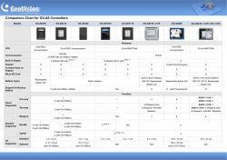

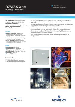
© Copyright 2026