
Procurement of Tube Bulging Test System
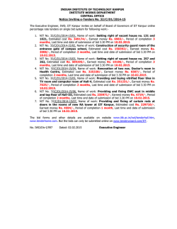
MECHANICAL ENGINEERING DEPARTMENT
INDIAN INSTITUTE OF TECHNOLOGY
KHARAGPUR – 721 302
Date: 28th Jan 2015
No. IIT/ME/ENQ/MF/SP/15/2
Last date for submission of bids: 20th February. 2015
Sub: Procurement of Tube Bulging Test System
Sealed quotations are invited for supply and installation of Tube Bulging Test System for Mechanical
Engineering Department with following specifications, as per standard terms and conditions of the
Institute.
System overview:
The Tube Bulging Test System is intended to pressurize the metal tube samples internally up to
1000bar by means of water pressure intensifier unit and laboratory study of the deformation /
bulging properties while it is subjected to axial compression loads up to 600kN by means of servo
hydraulic actuators. The pressurization and loading systems shall be integrated with each other and
shall have a common controller whilst having facility to control the loading through actuator
displacement control or load control mode and pressurization through displacement control or
pressure control.
Tube samples of Al, steels, Mg and other alloys for automotive/aerospace applications with
dimensions:
• Length: 500mm maximum
• ID: 60mm maximum
• Wall thickness: 3mm maximum
1. Loading Frame:
• ± 600kN Dynamic Capacity Fatigue Rated Two Column, Two cross head Self reacting
Load Frame
• Horizontally oriented frame suitable to mount 2 actuators on both sides
• Minimum horizontal clearance: 300mm
• Maximum horizontal clearance: 1200mm
• Frame Stiffness should be 600kN/mm or better
• Load frame mounted LCD Based touch screen control panel for Power Pack On/Off,
Emergency Stop, Actuator Jog Up & Down Slow & Fast, etc.
2. Servo hydraulic Actuators – 02 Nos:
•
•
Fatigue rated double acting, single ended actuator with an integrated manifold
± 600kN Fatigue Rated Load Capacity
Page 1 of 4
•
±75mm (total 150mm) displacement with built in LVDT or encoder for displacement
measurement with resolution of 0.001mm and accuracy of ± 0.5%
• Actuator speed range should be from 0.01 to 80 mm/min
• Suitable Servo valve for axial compressive load applications in Stroke, Load & pressure
control modes
• Suitable Servo controlled Power Pack shall be supplied by incorporating all safety
parameters for precise movement of actuators
3. Load Cells – 02 Nos:
1.
2.
3.
4.
5.
6.
7.
± 600kN Dynamic Capacity Load Cell
± 0.5% accuracy of read out value down to 1/100th of capacity
150% Safe Over Load Capacity
350 Ohm Strain Bridge design
Non Linearity: ± 0.15% of Full Scale or better
Hysteresis: ± 0.05% of Full Scale or better
Fatigue Life: 109 or better
4. Tube Pressurization System:
Specifications:
The entire system shall be mounted on a rigid base which has vibration resistance, corrosion
resistance. The test tube region should be covered so as to ensure no oil/fluid sprinkle on
the operator.
Pressure sensor:
• Working Range: 0 to 1000 bar (safety pressure rating 1500 bar).
• Accuracy: ±1bar
LVDT/Encoder:
• Range: 0 to 100mm.
• Accuracy: ± 0.01mm.
Motor Detail:
• 3 phase motor with VFD/servo motor.
• Class of insulation should be F and frame size shall be 100.
Parameter specification:
• Rate of pressurisation: 100, ±5 bar/min (1400, ±70 psi/min.)
• Adjustable pressurisation rate optional).
Pressurising fluid: Normal water/better medium
Data Acquisition/ software specification:
A PC Based Data Acquisition system with latest configuration comprising of following
Hardware to measure the Pressure and Piston movement precisely
• Pressure Sensing up to 1000 bar.
• Piston movement upto 100mm
5. Control Electronics:
Controller shall be of Digital Signal Processor (DSP) based closed loop 32 bit digital
controller/better. 32 Bit Data Acquisition on the control and feedback channels.
Page 2 of 4
Simultaneous Data acquisition rates of 24kHz or better from all primary channels. Feedback
loop update rates of 32kHz or better. Digital Input and Output lines minimum 08 Nos or
more. Provision for minimum 2 Analog Output channels to deliver ± 10VDC should be there.
Provision for minimum 2 Analog Input channels to accept ± 10VDC should be there. It should
readily accept 6 Primary Channels i.e, Position - 3, Load - 2 and Pressure – 1 with control
mode on each channel. Auto Calibration and Digital Auto Zero capability for all sensors shall
be available. Easy Downloadable Firmware for Future Up gradations, without making any
changes in the controller. Controller should be capable of conducting all the Tests mentioned
above. Should be capable of acquiring data from all control and feedback channels.
6. Soft ware:
•
•
Windows 7.0 based Software, facilitating basic operation of the system
Software should be capable of conducting tuning of all control channels with PID gain
control adjustment
• Should be capable of acquiring data from all channels
• Servo Loop Update rate of 32kHz and Simultaneous data acquisition rate of 24 KHz
• Should provide Position control, Load Control and Pressure control by default
• Automatic and Manual settable Data Acquisition rates for different test applications
• Electronic Safety Limit (user settable) Interlocks on all control channels to protect
Transducers and Actuators / Pressure Piston from over loading and over travelling
• All safety Parameters like, Over Temp of Oil, over and Under Pressure of oil and tube
pressure, Emergency Stop, Filter Clog Indication, Power Failure Indication, Motor over
load to be monitored by the software and should be displayed accordingly
• Should be capable of applying loads or pressures in different rates of loading &
pressurization
• Adaptive Control feature
• Required software to conduct tube bulging tests in Stroke, Load and Pressure control
modes
• General purpose application to create user defined test profiles
• Advanced graphics to view all feedback and set points on single and multiple graphs
• Software offered should be capable of generating the final test report including Raw
Data in the general purpose MS Office (Ex: Excel) format
The Software GUI shall consist of the following features:
• Pressure Vs. Time
• Pressure Vs. Piston Movement
• Pressure Vs. Load
• Load Vs. Change in Volume
• Pressure Vs. Change in Volume
• Calculation of Stored Energy, Total Circumferential Elongation, Hoop-Stress.
• Store the Test Graphs in files and a facility to view the tested samples and Graphs
• Report generation
• Store the results in Database and provisions to export into MS-Excel files
Techno-commercial conditions
A.
Interested original equipment manufacturers or dealers or agents may submit their quotations
in two bid systems (technical and commercial).
Page 3 of 4
B.
Warranty – minimum 1 year from the date of installation and commissioning at the site.
C.
Scope of supply should include free installation, commissioning and training at site.
D.
Please provide list of such supplied systems in India and abroad both in academics and
industry.
E.
Validity of the quotation should be 120 days from last date of submission
F.
In the technical bid, vendors have to give a technical compliance certificate along with the
technical literature.
G.
Commercial bid is to be provided in clearly marked separate sealed envelope.
H.
A Demand Draft in favour of “IIT Kharagpur” towards EMD value of Rs.1,00, 000/- (One Lakh
only) is to be provided along with the technical bid. Unsuccessful bidders will get back the EMD
amount after placing the Purchase Order to the successful bidder. For the successful bidder, the
EMD amount will be returned after successful installation and commissioning.
I.
Last date of submission of sealed quotation is 20th February, 2015, 15:00 hrs
J.
The date of opening of quotations (Technical bid) is 23rd February, 2015, 15:00 hrs
K.
L.
The date of opening of quotations (Commercial bid) is 26th February, 2015,16:00 hrs
The envelop should have the following number on the top:
No. IIT/ME/ENQ/MF/SP/15/2, dt.: 28th Jan 2015.
The quotation should be submitted to the office of:
Head of the Department
Attn : Prof. S.K. Pnda
Department of Mechanical Engineering
Indian Institute of Technology Kharagpur
Kharagpur, West Bengal 721 302
M.
N.
Regarding this purchase, the decision of the Director would be final and binding.
O.
Payment terms for foreign firms: 90% payment through irrevocable L/C against despatch
documents and balance 10% by wire transfer after satisfactory installation and commissioning
of the equipment and performance bank guarantee for warranty period.
Payment terms for Indian firms
P.
a) 100% payment through electronic transfer or A/c payee demand draft after receipt of store in
good order and condition. Generally payment is released after certification of bill which
typically takes 15 days.
b)
Ensure mentioning
i) Bank details of the beneficiary and PAN number
ii) Full name and address of the beneficiary on whom order has to be placed
Page 4 of 4


© Copyright 2026