
Extended abstract
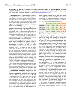
World Tribology Congress 2013 Torino, Italy, September 8 – 13, 2013 The effects of Lubricants with Additives on the Friction Force of Smooth and Artificially Textured Piston Rings Anastasios Zavos1), Pantelis Nikolakopoulos2)* 1) Department of Mechanical Engineering and Aeronautics, University of Patras, Patra, 26504 Patra, Greece 2) Department of Mechanical Engineering and Aeronautics, University of Patras, Patra, 26504 Patra, Greece * Corresponding author: [email protected] 1. Introduction The role of lubricant oil with additives in engine performance has been the subject of several studies in recent years. In particular, the influence of the piston ring pack with oil film has generated significant interest. The evolution of new generation C.I engines has created lubrication problems, that cannot be solved with mineral oils. This has led to the development of synthetic mixtures which the properties depend on from basic components as synthesis process and additives. The rheological behavior of low sulphated ash, phosphorus and sulfur lubricants, using an elastohydrodynamic tribometer and viscometer, investigated from Meunier et al. [1]. They examined the rheological parameters for fresh and aged lubricants, as well as the influence of particles sizes contained in the lubricants. Rajalingam et al. [2], developed a theory of piston ring lubrication considering a non-lubricant Newtonian oil. They presented the effects of pseudoplasticity to the minimum oil thickness, peak pressure ratio and friction coefficient. Wakuri et al. [3], presented in their paper an analytical and experimental study regarding the piston rings basic tribological parameters such us, the friction forces and oil film thickness. Their analytical model is based on the Reynolds equation, while the experimental results received using a four stroke diesel engine. Later on, these results have been used by the same authors to make predictions of the friction in the mixed lubrication regime. Hamatake et al. in [4], shown that the piston ring friction influenced from a kind of lubricant oil when contact occurred in the mixed lubrication regime. On the other hand, the first attempts for artificial textured piston rings on internal combustion engines, are reported in [5-7]. Etsion and Sher [5] presented an experimental work to estimate the effects of partially laser surface textured piston rings on the fuel consumption and on the exhaust gas composition of the ignition on the compression stage of an internal combustion engine. It was obtained that the partial surface texturing piston rings lead to more than 4% lower fuel consumption. Furthermore, Ryk and Etsion in [6] presented another experimental work regarding the effect of partial laser surface texturing on the friction reduction of the piston rings. In their results shown that, the partial laser textured piston rings improves the friction by 25%, than the relevant plain rings. Mezghani et al. [7] proposed a numerical simulation for the investigation of the effects of the groove characteristics on the lubrication performance, and on friction at the boundary between the piston ring and cylinder liner. In their study, the lubricant film rapture and the cavitation are taken into account. The present paper is divided in two parts. In the first part the effects of both types of oils (Newtonian and with additives) on the tribological characteristics of a smooth piston ring are investigated whereas in the second part the consequences on the textured ring are also examined. The Computational fluid dynamics (CFD) analysis is used in order to solve the Navier Stokes equations, calculating thus the pressure field between the piston and the ring for fully flooded lubrication. Further the non-Newtonian behavior of the oil is simulated using power law models. Simulation results from a diesel engine are presented for several parameters including friction forces and hydrodynamic pressures. 2. Geometrical analysis 2.1. Smooth and textured piston ring model The basic dimensions of a piston ring model presented in Figure 1a. The piston ring moving wall generates shear forces, exerting motion to the fluid, which flows from the piston ring inlet to the outlet. As the fluid convects, it builds up pressure, which exerts forces on the piston ring wall. Pressure buildup is due to the converging geometry, as a result of the ring deformation due to the chamber pressure, and also due to the presence of dimples of certain geometry. Energy is expended by the shear forces work done at the moving wall-fluid interface. Figure 1(a) Basic dimensions of piston ring model (b) Spherical geometry of dimples In Table 1, the input numerical parameters are depicted. The parameter, named B, is the thickness of the ring, tr is the length that is inside of the piston groove, tring is the free ring length inside the lubricant, tg is the distance from top of the first groove, tland is the lands between the ring grooves, h is the oil thickness, p1 is the combustion chamber gas pressure, L is the stroke length, rcr is the crank radius and lrod is the length of the rod. Table 1 Input numerical parameters L =120mm h=8μm tring=1.5mm tr=3mm p1=6.64MPa lrod=296mm B=2.4mm Ω=2400rpm tg=5.98mm Mass conservation equation, V 0 (1) Momentum equations, V 1 (2) V V p 2V t where V is the velocity vector, p is the pressure gradient, is the fluid density, μ is the absolute viscosity and t is time. Equations (1) and (2) are solved with the CFD code ANSYS Multiphysics. 3.1. Viscosity of non-Newtonian fluids λcr=0.27: control ratio(rcr/lrod) rcr=80mm tland=2.4mm For incompressible Newtonian fluids, the shear stress is proportional [8] to the rate-of-deformation tensor D : D (3) In Figure 1b, the geometry of a spherical micro dimple texturing is presented. Each spherical dimple has a base radius rp, the dimple depth Hd and the textured zone Lc is bounded with two untextured strips of width where D is defined by Lut Lud and μ is the viscosity, which is independent of D. For some non-Newtonian fluids, the shear stress can similarly be written in terms of a non-Newtonian viscosity μα: B N * Lc on each of its sides. The 2 below non dimensional parameters can be defined here: the number of dimples, N the textured portion, (4) a D D Lc B the dimensionless dimple diameter, u u D j i x x j i (5) However, in the non-Newtonian models the shear rate 2rp rcr H the dimple depth over diameter ratio, d 2rp It should be noted that, for rp=40μm, Hd=12μm and Lc=90μm, the values of the above non dimensional parameters take the values, N=16, γ=0.0375, δ=0.001 and ε=0.15. 3. Assumptions and Governing Equations This work is based on Navier Stokes equations solution using computational fluid dynamics (CFD). The main assumptions employed are given below. 1. The cylinder is stationary. 2. The flow is considered isothermal. 3. The piston ring is secured in the groove of the piston 4. The piston moves with a linear velocity in y axis, defined by the equation (9). 5. The oil temperature is considered constant along the cylinder wall. 6. The friction force between the piston ring and ring groove is also considered negligible. The conservation equations for unsteady incompressible and isothermal flow, with zero gravity and other external body forces, are: is defined as : 1 D:D 2 (6) 3.2. Power law for Non-Newtonian Viscosity Non-Newtonian flow will be modelled according to the following power law model, taking into account the non-Newtonian viscosity μα: a k o n1 where μο, k , n and (7) o are input parameters. In detail, μο is the nominal viscosity at 20 oC, k is a value of the average viscosity of the fluid, n is a measure of the deviation of the fluid from the Newtonian behaviour (the power-law index) and 0 is the cutoff shear rate. 3.3. Monograde and Multigrade Lubricant properties Three kinds of monograde lubricant and two kinds of multigrade lubricant are used. In Table 2 the lubricant properties are depicted. Table 2 Lubricant properties SAE viscosity grade Viscosity at 80 oC(mPas) 20 9.8 30 14 50 25 5W30 12.97 10W40 20.08 2 In addition, Table 3 shows the power law numerical parameters of multigrade lubricant oils. Table 3 Power law parameters Power law n k (s-1) o 5W30 10W40 0.89 0.91 0.8 0.78 2e+6 2e+6 μο(mPas) 80 95 5. Fluid Structure Interaction model-analysis The fluid structure interaction analysis presented in this paragraph. Figure 4, illustrates the flow chart of the solution of the couple field problems and the convergence criterion used. Additionally, the Arbitrary Lagrangian Eulerian (ALE) technique is used for the grid deformation (mesh morphing), of the fluid and structural problem. 4. Boundary conditions A four stroke diesel engine is considered here. The boundary conditions and the profile of combustion gas pressure p1=pc that defines the 2-D problem are shown in Figure 3. In fact, a limited loss of combustion gases because of the existence of the ring gaps through which the gas leaks were not considered to this stage. Figure 4 Solution flow chart 5.1. Meshing formulation Figure 3 Boundary conditions of the piston ring system Section 1 : Vx=0,Vy=V,Vz=0 Section 2 : Vx=0,Vy=V,Vz=0 Section 3 : Vx=0,Vy=0,Vz=0 4.1. Integral quantities The pressure distribution over the piston ring is obtained, after the numerical solution of the equation (2). In the present model, the friction force on the piston ring Regarding the fluid field solution, tetrahedral elements are used. Their size is on the scale of 3e-6, in the area near to the piston ring profile. The total number of 107080 elements for smooth case and 115053 elements for artificial textured which seemed adequate for the certain calculations are used. The particular number of elements and nodes were obtained for each examined case, after extensively grid sensitivity tests, while the pressure error considered as, Errpres 1E-6. Specifically, simulations were performed on the computer with 8 processors (Intel core i7-3770 CPU@ 3.40 GHz) and typical simulation time varied between 20 and 30 minutes for each crank angle. calculated by integrating the stress tensor above the ring surface A interfaced with the fluid film, and it is given by the below relationship: B Ff dA Dring 2B dy A (8) 2 Dring is the piston ring diameter and B is the piston ring thickness. The velocity of piston is calculated according to the next equation: V rcr (sin cr 2 sin 2 (9) The density-temperature relationship is: 1 Figure 5 Detail of fluid mesh 5.2. Validation results The present model is validated against published work of Wakuri et al. [3]. In particular, the piston ring friction force was calculated for fully flooded lubrication, illustrating a very good agreement (see figure 6). (10) where ρο is the fluid density at 20 oC (ρο=850 kg/m3) and a is the thermal expansion of the material (α=10.8 10-6 o -1 C ). 3 Figure 6 Validation results with ref. [3] (see figure 7). Friction force versus crank angle Figure 9 Maximum friction force vs crankshaft speed 6. Numerical Results and Discussion 7. Conclusions Figures 7a-b shows the friction force Ff in a smooth piston ring for Ω=2400rpm. It is depicted that the friction force increased when the viscosity increases, either for Newtonian lubricant or for lubricant with additives. In consequence, by using Newtonian oil the increment of the friction force is 50.9% while in the other case the increment is 44.09%. Conclusions are summarized as follows: 1. 2. 3. The friction force decreased having an artificial textured ring and lubricant with additives. The friction force decreased with the use of the lubricants with additives against to Newtonians, either for smooth ring or artificial textured ring. Increasing the viscosity, the increment of friction is obvious. Acknowledgement The Authors acknowledge the financial support by the Greek Secretariat for Research and Technology through the TRIBO-MARINE project, grant Nr. 2595. 8. References [1] Figure 7 Friction force vs crank angle for a. Newtonian oils and b. Lubricant with additives In Figure 8, the variation of the friction force in a carbon steel piston ring with spherical texturing, with SAE 30 and SAE 5W30 lubricants, is presented. The case of, N=16, γ=0.0375, δ=0.001 and e=0.15 examined in detail. In the point “A”, the maximum friction force decreased while the chamber pressure is maximum. In this case the reduction is 14.6%. [2] [3] [4] [5] [6] Figure 8 Friction force vs crank angle [7] The maximum friction force is illustrated in Figure 9, as a function of the rotational crankshaft velocity. The simulation results were performed for SAE 30 and SAE 5W30 oils, either for smooth ring or textured ring. From the results, it is obvious that using lubricant with additives and artificial textured ring, the friction reduction is 32.08%. [8] Meunier, C., Mazuyer, D.,Vergne, P., Fassi, M El., Obiols, J., “Correlation between the Film Forming Ability and Rheological Properties of New and Aged Low Sulfated Ash, Phosphorus and Sulfur (Low SAPS) Automotive Lubricants”, Tribology Transactions, 52:4, 2009,501-510. Rajalingam, C., Rao B.V.A., Prabhu B.S., “The effect of a non-Newtonian lubricant on piston ring lubrication”, Wear, 50,1978,47-57 Wakuri, Y., Hamatake, T., Soejima, M., and Kitahara, T., “Piston ring friction in internal combustion engines”, Trib. Int., 25, 5, 1992, 299. Hamatake, T., Wakuri, Y., Soejima, M., and Kitahara, T., “Effects of lubricant viscosity on the mixed lubrication of a piston ring pack in an internal combustion engine”, Lubrication Science, 15, 2, 2003, 101-117. Etsion , I., Sher E., “Improving fuel efficiency with laser surface textured piston rings’’, Tribology International, 42:4, 2009,542-547. Ryk, G., Etsion, I., “Testing piston rings with partial laser surface texturing for friction reduction”, Wear, 261, 7-8, 2006,792-796. Mezghani, S., Demirci, I., Zahouani, H., Mansori, M El., “The effect of groove texture patterns on piston-ring pack friction”, Precision Engineering, 36:2, 2012, 210–217. Gertzos, K.P., Nikolakopoulos, P.G., Papadopoulos, C.A, “CFD analysis of journal bearing hydrodynamic lubrication by Bingham lubricant”, Trib. Int., 41, 2008, 1190-1204. 4


© Copyright 2026