
Request-to-Exit Button INST-400Series
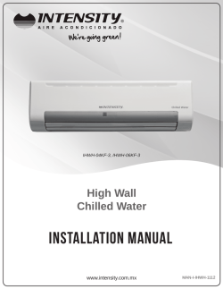
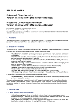
801 Avenida Acaso, Camarillo, Ca. 93012 • (805) 494-0622 •
www.sdcsecurity.com • E-mail: [email protected]
INSTALLATION INSTRUCTIONS
410/420 SERIES PUSH SWITCH
ORG (N/C)
Electrical Specifications
Contact Type: SPDT (Form C)
Contact Ratings: 30VDC @ 5 AMPS
(Resistive)
WHT (COM)
YEL (N/O)
RED
LAMP
28VDC
MAX
RED
P:\INSTALLATION INST\Push and Key Switch\INST-410-420.vsd
REV A
03-11
Page 1
Any suggestions or comments to this instruction or
product are welcome. Please contact us through
our website or email [email protected]
3580 Willow Lane, Westlake Village, CA 91361-4921 • (805) 494-0622 • Fax: (805) 494-8861
www.sdcsecurity.com • E-mail: [email protected]
INSTALLATION INSTRUCTIONS
MODEL 422 PUSH SWITCH
422GPE
422NGPE
ORG (N/C)
Electrical Specifications
Contact Type: SPDT (Form C)
Contact Ratings: 30VDC @ 5 AMPS
(Resistive)
WHT (COM)
YEL (N/O)
RED
LAMP
28VDC
MAX
RED
P:\INSTALLATION INST\Push and Key Switch\INST- 422.vsd
0305
Page 1
Any suggestions or comments to this instruction or
product are welcome. Please contact us through
our website or email [email protected]
SECURITY DOOR CONTROLS
801 Avenida Acaso, Camarillo, CA 93012 • (805) 494-0622
www.sdcsecurity.com • E-mail: [email protected]
INSTALLATION INSTRUCTIONS
MODEL 413NU & 423U PUSH SWITCH
1-60 SECOND ADJUSTABLE TIME DELAY
When the button is pressed, the lock releases for 1-60 seconds. If pressed again during the lock release period, the unit will
“Retrigger” starting a new release period.
Electrical Specifications
Input Voltage : 12/24VDC @90ma.
LED Indicator : 12/24VDC @ 10/20ma
Output Relay: DPDT
Max Load : 30VDC @ 5 AMP (Resistive)
1-60
SEC
TIMER
ADJ
POT
423U
413NU
TYPICAL WIRING
+
POWER
SUPPLY
-
+
-
12/24VDC
BLK TIMER
RED +
POWER
YEL/BLK
NO
WHT/BLK
COM
B
ORG/BLK
NC
YEL
NO
WHT
COM
A
ORG
NC
VIO
LED
BLU
12/24VDC
BLK TIMER
RED +
POWER
YEL/BLK
NO
WHT/BLK
COM
B
ORG/BLK
NC
YEL
NO
WHT
COM
A
ORG
NC
VIO
LED
BLU
413NU OR 423U
MANUAL RELEASE DEVICE
MD-31D
FAIL SAFE
REQUEST-TO-EXIT
SENSOR DEVICE
NC C NO
POWER
SUPPLY
413NU OR 423U
MANUAL RELEASE DEVICE
MD-31D
FAIL SAFE
REQUEST-TO-EXIT
SENSOR DEVICE
NC C NO
NC C NO V- V+
NC C NO V- V+
ACCESS CONTROL
POWER
SUPPLY
ACCESS CONTROL
MD-31D
NC
POWER
SUPPLY
MD-31D
NC
EMLOCK
NO
NO
C
FAIL-SAFE LOCK
1
4
POWER
+
-
P:\INSTALLATION INST\Push and Key Switch\INST-413NU-423U.vsd
2
5
3
6
7
8
9
*
0
#
FAIL SECURE LOCK
PUSH
TO
EXIT
ACCESS 413NU
CONTROL OR
423U
REV E
C
10-13
POWER
Page 1
+
-
ELECTRIC
STRIKE
1
2
4
5
3
6
7
8
9
*
0
#
PUSH
TO
EXIT
ACCESS 413NU
CONTROL OR
423U
Any suggestions or comments to this instruction or
product are welcome. Please contact us through
our website or email [email protected]
SECURITY DOOR CONTROLS
801 Avenida Acaso, Camarillo, Ca. 93012 • (805) 494-0622 • Fax: (805) 494-8861
www.sdcsecurity.com • E-mail: [email protected]
INSTALLATION INSTRUCTIONS
MODEL 413MN & 423M PUSH SWITCH
FIXED 30 SECOND TIME DELAY
This push to exit button is specifically intended for installation on Access Controlled Egress doors as described in the Boca
code. A motion detector is the primary means of releasing a magnetic lock on the door. The push to exit button is intended,
as a back up means of releasing the lock in the event there is a problem with the motion detector. When the button is
pressed, the lock releases for 30-seconds. If pressed again during the 30-seconds lock release period, the unit will
“Retrigger” starting a new 30-second lock release period.
TYPICAL WIRING
POWER
SUPPLY
+
12/24VDC
-
BLK TIMER
RED +
POWER
YEL/BLK
NO
WHT/BLK
COM
B
ORG/BLK
NC
YEL
NO
WHT
COM
A
ORG
NC
VIO
LED
BLU
413MN OR 423M
MANUAL RELEASE DEVICE
423M
413MN
Electrical Specifications
Input Voltage : 12/24VDC @90ma.
LED Indicator : 12/24VDC @ 10/20ma
Output Relay: DPDT
Max Load : 30VDC @ 5 AMP (Resistive)
MD-31D
FAIL SAFE
REQUEST-TO-EXIT
SENSOR DEVICE
NC C NO
NC C NO V- V+
POWER
SUPPLY
ACCESS CONTROL
MOTION
DETECTOR
EMLOCK
NC
NO
C
FAIL-SAFE LOCK
POWER
+
2
5
3
6
7
8
9
*
0
#
ACCESS
CONTROL
-
P:\INSTALLATION INST\Push and Key Switch\INST-413M-423M.vsd
1
4
REV D
02-13
Page 1
PUSH
TO
EXIT
MODEL 413MN/423M
PUSH TO EXIT
SWITCH
Any suggestions or comments to this instruction or
product are welcome. Please contact us through
our website or email [email protected]
801 Avenida Acaso, Camarillo, Ca. 93012 • (805) 494-0622 •
www.sdcsecurity.com • E-mail: [email protected]
INSTALLATION INSTRUCTIONS
414 & 424 PUSH SWITCH
424U
414NU
Electrical Specifications
Contact Type: DPDT (Form C)
Contact Ratings: 30VDC @ 5 AMPS
(Resistive)
WHT
(COM)
WHT
(COM)
YEL
(N/O)
YEL
(N/O)
ORG
(N/C)
ORG
(N/C)
RED
RED
RED
LAMP
28VDC
MAX
RED
P:\INSTALLATION INST\Push and Key Switch\INST-414-424.vsd
REV A
06-08
Page 1
Any suggestions or comments to this instruction or
product are welcome. Please contact us through
our website or email [email protected]
SECURITY DOOR CONTROLS
3580 Willow Lane, Westlake Village, CA 91361-4921 • (805) 494-0622 • Fax: (805) 494-8861
www.sdcsecurity.com • E-mail: [email protected]
INSTALLATION INSTRUCTIONS
MODEL 415N & 425 ON/OFF PUSH SWITCH
425
415N
Electrical Specifications
Contact Type: DPDT (Form C)
Contact Ratings: 30VDC @ 5 AMPS
(Resistive)
ORG (N/C)
WHT (COM)
RED
LED
BLK
GRN
YEL (N/O)
RED
ORG (N/C)
GRN
WHT (COM)
YEL (N/O)
P:\INSTALLATION INST\Push and Key Switch\INST- 415N-425.vsd
09-08
Page 1
Any suggestions or comments to this instruction or
product are welcome. Please contact us through
our website or email [email protected]
3580 Willow Lane, Westlake Village, CA 91361-4921 • (805) 494-0622 • Fax: (805) 494-8861
www.sdcsecurity.com • E-mail: [email protected]
INSTALLATION INSTRUCTIONS
MODEL 460
REQUEST – TO – EXIT - SWITCH
Adjustable
Timer
1 – 40 Seconds
12-24 VDC
NO 1
COM1
+
-
COM2
NC 2
*
With the jumpers
as shown the red LED’s are
on in stand-by and the green
LED’s turn on when the relay
is on.
Specifications
Selectable Bi-color Illumination Status
Relay Off – Red, Green or None
Relay On – Red, Green or None
Input Voltage: 12/24VDC
Current:
LED On: Idle-60mA, Active 120mA
LED Off: Idle-10mA, Active-60mA
Red On – Standby
Green On – Relay Action
Outputs:
1 N.O., 1 N.C., 2 Amp @ 30VDC
Red On – Relay Active
Green On - Standby
Switch Operating Environment
-40° F to +160°F (-40° C to +70°C)
Red Off
Green Off
Dimensions
4.5" H x 2.75" W x 1.25" D
(11.4 x 7 x 3.2 cm)
P:\INSTALLATION INST\Push and Key Switch\INST-460.vsd
*
0305
Page 1
Any suggestions or comments to this instruction or
product are welcome. Please contact us through
our website or email [email protected]


© Copyright 2026