
Three-wheeled mobile platform powered by LabVIEW at energy
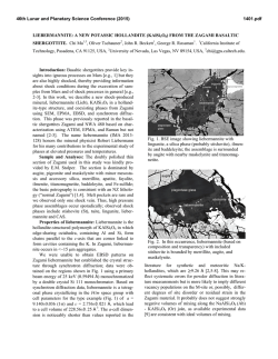
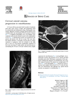
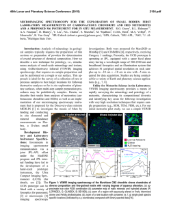
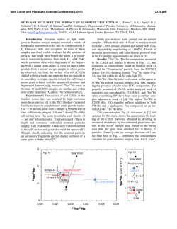
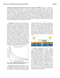
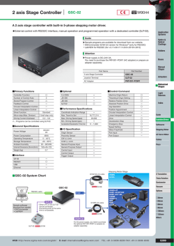
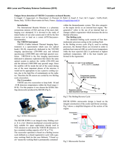
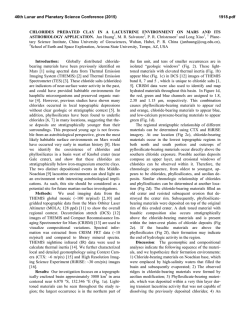
Nauka
Three-wheeled mobile platform powered by
LabVIEW at energy performance index
Krzysztof Kaliński, Cezary Buchholz
Gdańsk University of Technology
Abstract: Outstanding grow in demand both of mobile platform operability performance and efficiency of project development methodology encourage to apply modern algorithms and reliable engineering tools design. Latest research results confirm that the energy
performance index algorithm [1, 2] applied into strongly non-linear
mechatronic object developed by use of mechatronic techniques
can guarantee sufficient motion control in the reduced time design
process. In this paper the authors present three wheeled mobile
platform research object developed and controlled with a use of the
LabVIEW software environment. In order to boost mobile platform
performance and handle its real time surveillance motion process
the authors implemented the NI cRIO controller (dedicated Real
Time hardware powered by LabVIEW). Mathematical complexity
of on-line algorithm and sophisticated model description affected
all the process design. Presented paralleled design methodology
approach supported by mechatronic techniques [3] (virtual prototyping, Hardware-In-the Loop Simulations and rapid prototyping
on a target object) allowed authors to achieve the highest level of
a mobile platform system optimisation and increased probability of
the final concept success.
ted hardware. This paper discusses the mechatronic techniques (Virtual Prototyping, Hardware-In-the-Loop Simulations and Rapid Prototyping on the target object) supported by LabVIEW used during the design of the surveillance
system based on energy performance index. Proposed control algorithm was implemented into Real Time controller
cRIO-9076 powered also by LabVIEW and finally integrated with mobile platform (built for experimental purposes).
Presented research object allowed authors to verify responses
(for optimal control commands generated by Real Time controller) of the mobile platform while moving on three different trajectories (here the sine one is presented). This paper
is organised as follows. General platform model and control
algorithm are treated in section 2. Section 3 presents mechatronic techniques used during the research. In addition, partial experimental results are depicted. The mobile platform
is presented in section 4. Conclusions are given in section 5.
Keywords: mobile platform, LabVIEW, energy performance index,
mechatronic technique, real time
For research reasons, mathematical model of the mobile platform had to be established. An assumed model taken into
consideration is presented in fig. 1. Mobile platform is composed of following main parts: chassis 5, driving system ZN and
control system ZK. The driving system consists of two wheels 1 and 2, which thanks to differential mechanism are driven by one electrical motor 4. Wheels rotate about their axes,
whose positions are invariable in relation to the frame. Components of the control system are: wheel 3 embedded in steering wheel 6, which is driven by the other electrical motor 4.
1.Introduction
For mobile platforms operating in harsh environment, like
terrain or extraterrestrial planets (e.g. Moon or Mars) and
during demanding activities where not only human life is
exposed to high risk or performance of process is limited but
also precision, high effectiveness and sometimes long term
availability are considered, continuous motion, high operability and low power consumption are the core design factors.
Effective power management system with real time algorithms leads to reducing overall energy consumption, increases mobility performance and distributes wheels’ speeds
and moments in an optimal way [4, 5]. Increasing computation ability of processors, parallel processing architectures,
FPGA (Field Programmable Gate Array) usage and accurate sensors providing the opportunity for improvement of
control performance, reduce faults of tolerance and simplify
implementation of complex hardware and software design.
However, inadequate design cannot withstand environmental conditions and acquire precise motion control. Moreover,
not optimized control system causes dissipation of energy for
unnecessary CPU computations and heat losses. Therefore
the contemporary modern design process should be based on
mechatronic attitude in understanding the effects of dynamic model of the platform and supported by comprehensive
mechatronic development environment giving the possibility to prototype, design, simulate and integrate with dedica-
2.Mobile platform model. Control
algorithm approach
Fig. 1. Three-wheeled mobile platform model
Rys. 1.Model platformy mobilnej
Pomiary Automatyka Robotyka nr 12/2012
63
Nauka Coordinates a1, a2 and a3 are the rotational angles of
three mobile platform wheels 1, 2 and 3 respectively. The
angle of steering wheel is denoted by j. Angle b is the rotational angle displacement between the robot frame and fixed
coordinate axis x. Point H belongs to control system. Angle q
defines rotation of a mobile platform on a circular trajectory.
Point A is a point of intersection of the frame longitudinal
symmetry axis with the axis of rotation of wheels 1 and 2.
Dynamics of controlled nonlinear mobile platform can be
described as [1]:
(1)
where signs M*, L*, K*, B*, q*, f* and u denote respectively matrices of inertia, damping, stiffness and control, and
also vectors of generalised displacements, forces and control
commands of the system. Assuming that mobile platform
moves on the flat surface, and considering changing with
time kinetic energy of the system relatively to trajectory of
given motion and du ¹ 0, an optimal control command, for
sampling time ∆t, can be formulated [1]:
(2)
Defined control command u(t) for the mobile platform at
time instant t, is calculated on a basis of matrices M and L,
whose values are generated for time instant t–∆t.
Representing a step of integration ∆t is limited by CPU
performance of applied mobile platform controller (here is
National Instruments cRIO-9076, 400 MHz, powered by
LabVIEW) and has considerable impact on situation where
any control command is generated. A lack of control signal
(during time period ∆t) can cause significant deviations
between actual and desired trajectory of the platform, and
thus disturbs energy system balance. Authors followed by the
research goals wanted to build system with minimal energy
losses (error minimization). Common approach encourages
decreasing to minimum time ∆t (mainly by speed up CPU
clock frequency) and find minimal error level. In this study
limitations of applied controller had
to be considered. Fixed CPU clock
and willingness to keep application’s real time determinism forced authors to find balance between time
∆t and error level occurrence.
During the study authors investigated remedies for described system balance and defined suitable
correction velocities and implemented them into the optimal control
command u(t). Defined correction
velocities can be given as:
(4)
where: Q – dimensionless matrix of influence of kinetic energy,
ˆ – vectors
R – matrix of the control command’s effect, q , q, q
of actual generalised velocities, generalized velocities in the desired motion, and correction velocities. For time ∆t, where the
time determinism is hold, applied correction velocities can lead
to elimination of the mobile platform error occurrence and
improve considerably system energy efficiency.
In considered research by use of presented in section 3 of
this paper mechatronic techniques, optimal signal generation time ∆t was established. During the virtual prototyping
technique (first stage of this study) authors adjusted ∆t for
0.001 s, but demanding computation process of on-line algorithm and real time conditions (equalization between simulation and real time clock readings) of the HILS tests verified previous assumptions and final ∆t was set for 0.005 s.
Having ability to use FPGA (integral part of applied controller), authors decided to allocate there certain parts of the
algorithm code (responsible for PWM formation). By this
move considerable increase of controller output level (decreasing of CPU and memory usage) was obtained.
3.Mechatronic techniques. Design
methodology supported by LabVIEW
Latest tendency in mechatronic design requires the use of comprehensive development environment giving the possibility to
prototype, design, simulate and integrate with dedicated hardware. Similar concept was used to design and develop surveillance system for three wheeled mobile platform.
In order to have a system which reflects research needs, the
mobile platform was also, first designed and afterwards created.
Design methodology used during the research was presented in fig. 2.
(3)
where: x H and yH – Cartesian coordinates describing desired position of
characteristic point H of the platform
in time t; xH and yH – Cartesian coor-
64
dinates describing actual position of characteristic point H of
the platform in time t; k – coefficient determined in a way of
simulation [6]. Bearing in mind defined correction velocities,
ˆ can be calculated and optivector of correction velocities q
mal control command (eq. 2) can be modified as follows:
Fig. 2. General overview for mechatronic techniques used during
the research
Rys. 2. Przyjęta koncepcja projektowania mechatronicznego
Techniques of Virtual prototyping, HILS and finally – rapid prototyping on real target object, were used to assist researchers to complete development process of complex mobile platform surveillance system and achieve (by optimisation of algorithm, configuration, control strategy) highest
performance integration with the mobile platform design.
3.1. Virtual prototyping
Modern machines developed to withstand critical operation,
but also contemporary ordinary mechatronic devices or customer demands are facing growing challenges. These include
verifying more complex mechanical design, hardware and
software in a timely and cost effective manner. It also requires to communicate efficiently their specification across design
methodology. Virtual prototyping is a technique where authors
by creation of virtual model of the mobile platform (differential equations of the mobile platform were computed symbolically in the Maple software; parametrical solutions were implemented into LabVIEW) were able in shortened time to verify
responses (on PC) for optimal signals generated by proposed
algorithm (virtually implemented into LabVIEW software).
General overview of applied technique was shown on fig. 3.
During this stage of study (virtual prototyping), it was necessary, firststly to guaranty correctness of algorithm implementation (into the LabVIEW) and secondly (in parallel) to
achieve optimisation both in controller architecture and model of the mobile platform (by establishing boundary conditions for the final design).
Optimal control signals (torques), defined by eq. 4 were
shown in fig. 4 and fig. 5 (for the sine trajectory). In order to
verify implementation process of controller and adjust properly coefficients of R and Q matrices (of algorithm) desired solutions (of Langrage equations solved during virtual simulation) together with optimal signals were generated. Similar process was applied for model optimisation, where authors by comparing parameters of the mobile platform kinematics with desired values (generated in the same time) were
able to finalize the model design. Responses for the sine trajectory were presented in fig. 6, fig. 7 and fig. 8. It is seen that
virtual platform moves on proper trajectories with small error whose occurrence can be explained by high nonlinearity
of the model design and applied numerical computation process. With a use of virtual prototyping technique authors in
shortened time period achieved desired implementation of the
energy performance index and were allowed to conduct complex optimisation process of the controller software architecture (software debugging, pre-adjusting matrices R and Q).
Additionally, numerous values of the mobile platform parameters were verified.
Fig. 4. Steering wheel torque
Rys. 4. Moment kierujący
Fig. 5. Propulsion torque
Rys. 5. Moment napędowy
Fig. 6. Wheel speeds (virtual prototyping)
Rys. 6. Prędkości kątowe poszczególnych kół
3.2. HILS
Fig. 3. Virtual prototyping concept
Rys. 3. Koncepcja wirtualnego prototypowania
The concept of the HILS technique has been recognized as
effective method for prototyping and design. Authors by the
use of the Real Time LabVIEW module performed deterministic test configuration where in synchronism both emulated mobile platform (virtual model created during previous stages of the research) and the real control system (here
controller NI cRIO-9076) were tested.
In the presented study the HILS technique with its low
cost and flexibility was used to assist researchers to complete
development process of complex mobile platform surveillance
Pomiary Automatyka Robotyka nr 12/2012
65
Nauka Fig. 7. Frame angle (virtual prototyping)
Rys. 7. Chwilowa wartość kąta obrotu platformy
Fig. 8. Steering wheel angle (virtual prototyping)
Rys. 8. Chwilowa wartość kąta obrotu kierownicy
gned algorithm (eq. 4) implemented into the NI-9076 controller generated in real time for each (defined) trajectory
optimal signals (torques). Responses (also in real time) by
use of experimental adjustment of matrices R and Q were
verified. Control signals (the same as during virtual prototyping) and responses were shown in fig. 11, fig. 12 and fig.
13 respectively. As it was done before, in order to perform
verification process correctly, the reference (desired) value
for each response was drawn.
Due to the specific setup of the performed test, where virtual model of the research object is investigated (emulated
three wheeled mobile platform) differences between responses obtained by the HILS technique and desired values can
be seen (virtual simulation). The authors’ research experience taken from this study suggests several aspects which
should be considered in the final test evaluations. Considerable meaning in the HILS test results has mathematical model of the research. High non-linearity of the model
(mainly inertia matrix) affects difficulties in control stability (matrix coefficients addicted to steering wheel angle).
Additionally sophisticated computational process of differential equations impacts on numerical errors occurrence.
Despite existed differences the test purpose was achieved.
By fulfilling time determinism requirement a sufficient integration time was applied and system energy balance on this
stage of study was obtained. Modification of code algorithm execution, where authors decided to split the process
for two controller locations: one executed in real time processor and the other executed in the FPGA increased final
system performance.
Conducted specific methodology in a surveillance system
design resulted possibility of testing different system configurations during different operation conditions avoiding
unnecessary damage and without having to build. Occurring
similarities in model responses acknowledged that surveillance system was designed correctly with optimal energy
configuration efficiency and the success of final integration
with real mobile platform can be expected.
system and achieved (by optimisation of algorithm, configuration, control strategy) highest performance of the design.
Experimental setup was presented in fig. 9, where in real
time tests the researchers verified response of emulated mobile
platform model for control signals
(torques) generated by real time
controller (where designed algorithm was executed). The authors
demonstrated in fig. 10 suitable block diagram where real
time controller generates torques
signals (i.e. M1, M2 – specific
for each trajectory) which via IP
network (buffered real time variables were used) are sent to the
emulated mobile platform. Based
on received torques (M1, M2), in
real time process (PC with installed Labview Real Time module)
forward dynamic and forward
kinematic equations are resolved.
The test was performed for three
different mobile platform trajectories: circular, parabolic and sinusoidal (the sinusoidal one is pre- Fig. 9. Experimental setup of the HILS test
sented in this paper). The desi- Rys. 9. Stanowisko pomiarowe w technice HILS
66
Fig. 10. Block diagram of the HILS test
Rys. 10. Schemat blokowy w technice HILS
Fig. 11. Wheel speeds (HILS)
Rys. 11. Prędkości kątowe poszczególnych kół
2. Mobile platform validation
while moving on desired trajectories (verification of algorithm performance). 3. Algorithm debugging and control sysFig. 12. Frame angle (HILS)
Fig. 13. Steering wheel angle (HILS)
tem adjustments (the R and Q
Rys. 12. Chwilowa wartość kąta obrotu platformy
Rys. 13. Chwilowa wartość kąta obrotu kiematrices, PWM). Checking prorownicy
cedure of algorithm performance was executed by measuring
deviation between real position
3.3. Rapid prototyping on a real target object
of the platform and point 0 of the Cartesian coordinate system 0xy located on desired trajectory. For every trajectory
Very often, when the system or the object exists and in the
the authors established several places where the measuresame time there is still a need to implement new (machine or
ments were taken. The sine test trajectory with check points
is presented in fig. 15. The authors in fig. 16 (left) demonone of the part will be automated) or upgrade the old constrated result for the last point of the trajectory taken when
trol system (new functionality was introduced) rapid prototyping on real (existing) object is frequently used. In classical
the mobile platform moved with 0.17 m/s. Fig. 16 (right)
approach, machine controller is prototyped on high advance
presents results for the same check point but speed of the
real time hardware (i.e. cLogic card) where, by support of
platform was set for 0.31 m/s (90 % of max. speed). It is
necessary to state that preliminary assumptions suggested
dedicated development software environment, control algothat mobile platform would be moving with 0.17 m/s, but
rithm can be designed and on the fly compiled. During previous (applied in this study) mechatronic techniques the
surprisingly during the commissioning of the system maxioptimal architecture of surveillance system was worked out
mal speed was verified to 0.35 m/s. Significant discrepancy
is explained by better power efficiency of the DC propulsion
and designed mobile platform was built. As it was mentioned before the authors decided to use the cRIO controlengine that it was anticipated and lower gear in the diffeler as a hardware platform for control motion of the mobile
rential system as it was given by part distributor. The test
results for both applied speeds confirm sufficiently good perrobot. Existing both object and control hardware encouraformance of proposed method to control strongly nonlinear
ged authors to modify current survey (technique) and connect prototyping process with the final implementation (and
object. During the test the mobile platform reached the final
validation). A concept of the prototyping test setup configudestination with demanding repeatability. Small error occurration was show in fig. 14. Considering (iteration) developrence can be avoidable by comparison with the complexity of
the trajectory, the distance to travel and the size of object.
ment process was organized as follows: 1. Algorithm compilation and deployment to controller (Real Time and FPGA).
Numerical errors should be also considered.
Pomiary Automatyka Robotyka nr 12/2012
67
Nauka 4.Three wheeled
mobile platform
powered by
LabVIEW
A concept of the object
mechanical construction
appeared in early phase of
the research and as it was
presented in fig. 2, the main
idea was to base propulsion
system on differential gear
connected centrally to electrical motor (Micromotors).
Development process performed together (in number of iterations and feedbacks) with surveillance
systems design affected to
build mobile platform whose final form (used during
experiment) was depicted
in fig. 17 (left) (front-side view) and fig. 17 (right)
(bottom view). The electrical line scheme was shown
in fig. 18. The main component of the presented system was based on cRIO
NI-9076 controller powered
by LabVIEW, where the
proposed algorithm is computed. Modules NI-9505
play significant role in DC
Fig. 16. Experimental results
Rys. 16. Rezultaty przeprowadzonych doświadczeń
Fig. 17. Three wheeled mobile platform
Rys. 17. Trójkołowa platforma mobilna
Fig. 14. Block diagram of rapid prototyping on target object
Rys. 14. Schemat blokowy techniki szybkiego prototypowania na
obiekcie docelowym
Fig. 15. Test trajectory for mobile platform
Rys. 15. Trajektoria typu sinus
68
Fig. 18. Mobile platform electrical scheme
Rys. 18. Schemat układu elektrycznego
motor control (PWM generation) and give the interface to
optical encoders with high resolution (1000 impulses per
motor rotation). Optimised level of signal generation frequency forced authors to apply only such solutions which parameters or its characteristics would not influence time system response (i.e. 0.005 s). The cRIO controller concept by
high-end and flexible architecture allows to develop deterministic application both in real time processor and FPGA.
Authors used this convenience and by splitting algorithm for
two parts (as it was mentioned above) afterwards deployed
them one by one to dedicated controller location.
5.Conclusion
The presented research study in this paper, supported by
LabVIEW, allowed by use of mechatronic techniques to develop mobile platform surveillance system and implemented
into real time controller (powered by the same software environment).
Validation in conjunction with rapid prototyping on real
object confirmed in experimental way, that proposed energy performance index can be widely used to control nonlinear systems.
Tested with success mobile platform trajectory variants
and movement speeds guarantee algorithm flexibility in future implementations.
The authors, in order to reduce the project cost, applied
the HILS technique to design system with the highest controller performance and energy optimisation. In addition, significant reduction of time verification and extended test possibility of the other design variants were achieved.
Bibliography
1. Kaliński K., Nadzorowanie drgań układów mechanicznych modelowanych dyskretnie, Wyd. Pol. Gdańskiej,
2001, 28–35.
2. Galewski M, Kaliński K., Nadzorowanie drgań przy frezowaniu szybkościowym smukłymi narzędziami ze zmienną prędkością obrotową, Wyd. Pol. Gdańskiej, 2009,
59–63.
3. Petko M., Wybrane metody projektowania mechatronicznego, Instytut Technologii Eksploatacji – PIB, 2008,
15–36.
4. Kaliński K., Buchholz C., Trajectory optimal control of
three wheeled mobile platform at time changeable energy performance index, 10th Conference Active Noise and
vibration control methods, 2011, Cracow, Poland.
5. Kaliński K., Buchholz C., Error minimisation in orientation and localization by correction velocities for three-wheeled mobile platform at time changeable energy
performance index, 16th International Conference on
Methods and Models in Automation and Robotics, 2011,
Międzyzdroje, Poland.
6. Kaliński K., Buchholz C., Mobile platform power optimisation by control command at time changeable energy performance index, Annual International Workshop
2011 – Dynamic Behaviour of Structures and Materials,
Interaction and Friction, 2011, Metz, France.
Środowisko LabVIEW w projektowaniu
mechatronicznym trójkołowej platformy mobilnej
przy energetycznym wskaźniku jakości
Streszczenie: Rosnące wymagania stawiane platformom mobilnym, w zakresie wysokiej operacyjności oraz sprawności energetycznej, skłaniają do stosowania wydajnych algorytmów sterowania ich ruchem, a także efektywnych środowisk projektowania mechatronicznego. Badania autorów są dowodem skuteczności sterowania optymalnego przy energetycznym wskaźniku jakości [1, 2], jako trafnej metody w zastosowaniu do obiektów silnie
nieliniowych. Zaimplementowany do systemu sterowania algorytm,
którego koncepcja bazuje na rozpatrywanym wskaźniku jakości,
zagwarantował przejazd platformy po wytypowanych trajektoriach
z oczekiwaną dokładnością. W artykule opisano koncepcję trójkołowej platformy mobilnej, powstałą jako efekt zastosowania wybranych technik projektowania mechatronicznego, czyli [3] wirtualnego prototypowania, HILS (Hardware-In-the-Loop Simulations) oraz
szybkiego prototypowania na obiekcie docelowym. Wraz z systemem sterowania bazowało ono na zintegrowanym środowisku
LabVIEW. Złożoność matematyczna zastosowanego algorytmu
on-line oraz modelu obliczeniowego platformy, a także konieczność sterowania obiektem w czasie rzeczywistym, wymagały użycia dedykowanego sterownika platformy. Wybór jednostki National Instruments cRIO, wraz z zastosowanymi technikami projektowania mechatronicznego, pozwoliły autorom osiągnąć zakładaną skuteczność sterowania platformą mobilną, przy jednoczesnym
spełnieniu warunku optymalizacji energetycznej systemu, a także
ograniczyć znacząco czas realizacji projektu platformy.
Słowa kluczowe: platforma mobilna, LabVIEW, energetyczny
wskaźnik jakości, mechatronika, czas rzeczywisty
Professor Krzysztof Kaliński, PhD
He is professor in applied mechanics
and mechatronics, Faculty of Mechanical Engineering, Gdańsk University of Technology. He developed his
expertise and experience in scope of
machine dynamics, robotics, vibration
engineering and high speed machining. His research interests concern
mechatronic design, dynamics and
optimal control, as well as structural
and strength analysis.
e-mail: [email protected]
Cezary Buchholz, MSc
He performs his PhD theses in Faculty
of Mechanical Engineering, Gdansk
University of Technology. He received his MSc in Faculty of Electronics
and Telecommunications and Informatics, Gdańsk University of Technology. He maintains a wide interest
in many areas of mechatronics and
electronics especially focused on real
systems, LabVIEW programming and
power electronics.
e-mail: [email protected]
Pomiary Automatyka Robotyka nr 12/2012
69

© Copyright 2026