
dse2157 dsenet® output expansion module
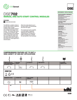
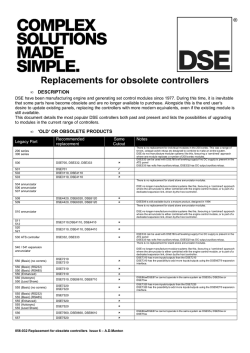
®
DSEGenset
DSE2157
DSENET OUTPUT EXPANSION MODULE
ENVIRONMENTAL TESTING STANDARDS
ELECTRO-MAGNETIC COMPATIBILITY
BS EN 61000-6-2
EMC Generic Immunity Standard for
the Industrial Environment
BS EN 61000-6-4
EMC Generic Emission Standard for
the Industrial Environment
®
ELECTRICAL SAFETY
BS EN 60950
Safety of Information Technology Equipment,
including Electrical Business Equipment
The DSE2157 is an output relay
expansion module for use with
DSENet® compatible control
modules. The DSE2157 has been
designed to extend a host
module’s output capabilities.
A maximum of 10 DSE2157’s can
be connected to an individual
module at any one time. All outputs
are configurable via the host
controller.
The additional output capabilities of
the DSE2157 give OEMs the
flexibility to meet increasingly
complex industry specifications.
The module incorporates ‘DIN’ rail
and chassis mountings allowing
convenient fixing into a panel.
TEMPERATURE
BS EN 60068-2-1
Ab/Ae Cold Test -30 oC
BS EN 60068-2-2
Bb/Be Dry Heat +70 oC
VIBRATION
BS EN 60068-2-6
Ten sweeps in each of three
major axes
5 Hz to 8 Hz @ +/-7.5 mm,
8 Hz to 500 Hz @ 2 gn
The module will work up to 1 KM
(0.6miles) from the host control
module.
HUMIDITY
BS EN 60068-2-30
Db Damp Heat Cyclic 20/55 oC
@ 95% RH 48 Hours
BS EN 60068-2-78
Cab Damp Heat Static 40 oC
@ 93% RH 48 Hours
SHOCK
BS EN 60068-2-27
Three shocks in each of three major axes
15 gn in 11 mS
COMPREHENSIVE FEATURE LIST TO SUIT A WIDE VARIETY
OF GEN-SET APPLICATIONS
HOST MODULE (1)
1
DSENET®
EXPANSION
DC POWER
SUPPLY 8-35V
COMPATIBLE WITH DSE7310/20, DSE8610/60/80 & DSE8710/60
DSE2157
DSENET®
HOST MODULE
7
2157
2130
2510/20
2548
OTHER
VOLT-FREE NORMALLY OPEN OUTPUTS
VOLT-FREE CHANGE OVER OUTPUTS
4
4
ISSUE 3
®
DSEGenset
DSE2157
DSENET OUTPUT EXPANSION MODULE
®
SPECIFICATION
DC SUPPLY
CONTINUOUS VOLTAGE RATING
8 V to 35 V Continuous
CRANKING DROPOUTS
Able to survive 0 V for 50 mS, providing
supply was at least 10 V before dropout
and supply recovers to 5 V. This is
achieved without the need for internal
batteries. LEDs and backlight will not be
maintained during cranking.
MAXIMUM OPERATING CURRENT
325 mA at 12 V, 152 mA at 24 V
MAXIMUM STANDBY CURRENT
70 mA at 12 V, 32 mA at 24 V
AUXILIARY RELAY CONTACTS
2 Amp DC rated voltage free
DIMENSIONS
OVERALL
165 mm x 76 mm x 49 mm
6.5” x 3” x 1.9”
KEY FEATURES
• Power On/Link Lost LED ID
SWITCH
• 10 expansion modules can be
connected to 1 host controller at
a time
• 8 configurable relay contacts
with LED indicators:
- 4 Normally Open (N/O)
- 4 Change Over (C/O)
• Terminal strip connection for
quick and easy set-up
ID SWITCH
The rotary ID switch is used to
select the address of the DSE2157
expansion module, as the host
control module is capable of giving
instructions to a number of
DSE2157 expansion modules at
the same time.
RELATED MATERIALS
TITLE
DSE2157 Installation Instructions
DSE2157 Operator Manual
PART NO’S
053-034
057-083
DEEP SEA ELECTRONICS PLC UK
Highfield House, Hunmanby Industrial Estate, Hunmanby YO14 0PH
TELEPHONE +44 (0) 1723 890099 FACSIMILE +44 (0) 1723 893303
EMAIL [email protected] WEBSITE www.deepseaplc.com
DEEP SEA ELECTRONICS INC USA
3230 Williams Avenue, Rockford, IL 61101-2668 USA
TELEPHONE +1 (815) 316 8706 FACSIMILE +1 (815) 316 8708
EMAIL [email protected] WEBSITE www.deepseausa.com
Deep Sea Electronics Plc maintains a policy of continuous development and reserves the right to change
the details shown on this data sheet without prior notice. The contents are intended for guidance only.
Registered in England & Wales No.01319649
VAT No.316923457
055-061/10/10 (3)


© Copyright 2026