
download book here - 10 Top Free eBooks
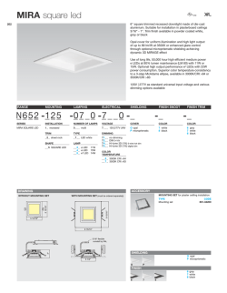
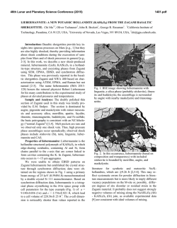
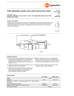
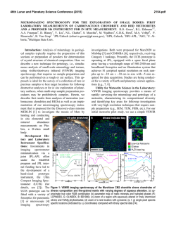
Level measurement in bulk solids
Radar
VEGAPULS 67
VEGAPULS 68
Product Information
Contents
Contents
6
7
8
Description of the measuring principle. . . . . . . . . . . . . . . . . . . . . . . . . . . . . . . . . . . . . . . . . . . . . . . . . . 4
Type overview. . . . . . . . . . . . . . . . . . . . . . . . . . . . . . . . . . . . . . . . . . . . . . . . . . . . . . . . . . . . . . . . . . . . . 5
Mounting instructions . . . . . . . . . . . . . . . . . . . . . . . . . . . . . . . . . . . . . . . . . . . . . . . . . . . . . . . . . . . . . . . 7
Electrical connection
4.1 General requirements . . . . . . . . . . . . . . . . . . . . . . . . . . . . . . . . . . . . . . . . . . . . . . . . . . . . . . . . . . . . 10
4.2 Power supply . . . . . . . . . . . . . . . . . . . . . . . . . . . . . . . . . . . . . . . . . . . . . . . . . . . . . . . . . . . . . . . . . . 10
4.3 Connection cable . . . . . . . . . . . . . . . . . . . . . . . . . . . . . . . . . . . . . . . . . . . . . . . . . . . . . . . . . . . . . . . 10
4.4 Connection of the cable screen and grounding. . . . . . . . . . . . . . . . . . . . . . . . . . . . . . . . . . . . . . . . . . 10
4.5 Wiring plan . . . . . . . . . . . . . . . . . . . . . . . . . . . . . . . . . . . . . . . . . . . . . . . . . . . . . . . . . . . . . . . . . . . 11
Operation
5.1 Overview . . . . . . . . . . . . . . . . . . . . . . . . . . . . . . . . . . . . . . . . . . . . . . . . . . . . . . . . . . . . . . . . . . . . . 12
5.2 Adjustment with the indicating and adjustment module PLICSCOM . . . . . . . . . . . . . . . . . . . . . . . . . . . 12
5.3 Adjustment with PACTware. . . . . . . . . . . . . . . . . . . . . . . . . . . . . . . . . . . . . . . . . . . . . . . . . . . . . . . . 12
5.4 Adjustment with other adjustment programs . . . . . . . . . . . . . . . . . . . . . . . . . . . . . . . . . . . . . . . . . . . . 13
Technical data. . . . . . . . . . . . . . . . . . . . . . . . . . . . . . . . . . . . . . . . . . . . . . . . . . . . . . . . . . . . . . . . . . . . 14
Dimensions . . . . . . . . . . . . . . . . . . . . . . . . . . . . . . . . . . . . . . . . . . . . . . . . . . . . . . . . . . . . . . . . . . . . . . 19
Product code. . . . . . . . . . . . . . . . . . . . . . . . . . . . . . . . . . . . . . . . . . . . . . . . . . . . . . . . . . . . . . . . . . . . . 22
2
Radar – Level measurement in bulk solids
1
2
3
4
5
31488-EN-081121
31488-EN-081121
Contents
Take note of safety instructions for Ex applications
Please note the Ex specific safety information which you can find on our homepage www.vega.com\services\downloads and
which comes with every instrument. In hazardous areas you should take note of the appropriate regulations, conformity and
type approval certificates of the sensors and power supply units. The sensors must only be operated on intrinsically safe
circuits. The permissible electrical values are stated in the certificate.
Radar – Level measurement in bulk solids
3
Description of the measuring principle
1
Description of the measuring principle
Measuring principle
Extremely short microwave pulses with low emitted power are
transmitted by the antenna system to the measured product, reflected by the product surface and received back by the antenna
system. Radar waves travel at the speed of light. The time from
emission to reception of the signals is proportional to the level in
the vessel. A special time stretching procedure ensures reliable
and precise measurement of the extremely short transmission
periods.
1.1
Application examples
Plastic granules
The latest microprocessor technology and the proven software
ECHOFOX select the level echo from among a large number of
false echoes and measure it precisely.
By simply entering the vessel dimensions, a level-proportional
signal is generated from the distance. It is not necessary to fill
the vessel for the adjustment.
Wide application range
VEGAPULS 67 and 68 radar sensors are particularly suitable for
level measurement of bulk solids. The mechanical construction
as well as the electronics were optimized for this application.
Through the special horn and parabolic antennas and the improved dynamic range of the receiver, levels in measuring ranges
up to 70 m (230 ft) can be measured. A reliable measurement is
possible with dielectric values from 1.6.
Fig. 1: Level measurement in a plastic granules silo with VEGAPULS 67
Plastic granules and powder are often stored in high, narrow silos
which are filled pneumatically. Typical conditions are filling noise,
material cones and poor reflective properties.
The high sensitivity of the VEGAPULS 67 sensor guarantees
ample performance reserves for reliable level measurement even
with widely varying product surface geometries.
Clinker silo
Versions for real-world applications
Adaptable sensors are required for the widely varying product
characteristics and mounting situations. That is why VEGAPULS
67 and 68 radar sensors are available with flange fittings, mounting strap as well as swivelling holder. An integrated connectionfor
air rinsing is also available with VEGAPULS 68. An optional temperature adapter extends the application range to product temperatures up to 200 °C (392 °F). Mounting is very easy and requires no additional work at the measuring site.
Fig. 2: Level measurement in a clinker silo with VEGAPULS 68
Independent of product properties
Fluctuations in product composition or even complete product
changes do not influence the measuring result. A fresh adjustment is not necessary.
Device selection
VEGAPULS 67 and 68 radar sensors are available with different
horn and parabolic antennas. This yields a variety of instrumentspecific beam angles and measurement characteristics. The selection of a suitable antenna depends on the respective application. For detailed selection you can use the tools "Finder" and
"Configurator" on our website or contact one of our agencies.
Clinker is an additive for concrete and is stored in large silos or
bunkers. Its abrasive properties as well as extreme dust generation during filling place heavy demands on the level measurement.
The VEGAPULS 68 sensor is the optimum solution for level
measurement. Its parabolic antenna powerfully focuses the microwaves, thus generating a strong useful signal. Interference
from struts or installations is excluded.
31488-EN-081121
4
Radar – Level measurement in bulk solids
Type overview
2
Type overview
VEGAPULS 68
Preferred application:
Bulk solids
Bulk solids
Measuring range:
up to 15 m (49.21 ft)
up to 70 m (229.66 ft)
Process fitting:
Mounting strap, compression flange, adapter flange
Thread, swivelling holder, flange
Material:
PPH
316L, Hastelloy C22 plated, Hastelloy C22
Process temperature:
-40 … +80 °C (-40 … +176 °F)
-40 … +200 °C (-40 … +392 °F)
Process pressure:
-1 … 3 bar/-100 … 300 kPa (-14.5 … 43.51 psig)
-1 … 40 bar/-100 … 4000 kPa (-14.5 … 580.2 psig)
Signal output:
4 … 20 mA/HART in two-wire, four-wire, Profibus PA,
Foundation Fieldbus technology
4 … 20 mA/HART in two-wire, four-wire, Profibus PA,
Foundation Fieldbus technology
Adjustment/Indication:
PLICSCOM
PLICSCOM
Remote adjustment/
indication:
VEGADIS 61
VEGADIS 61
31488-EN-081121
VEGAPULS 67
Radar – Level measurement in bulk solids
5
Type overview
Indicating and adjustment
module
PLICSCOM
Housing
Plastic
Stainless steel
Aluminium
Aluminium (double
chamber)
4 … 20 mA/HART
4 … 20 mA/HART
four-wire
Profibus PA
Foundation Fieldbus
Thread
Flange
Flange with swivelling holder
Plastic horn antenna
Stainless steel horn
antenna
Parabolic antenna
FM
CSA
Electronics
Process fitting
Sensors
Approvals
31488-EN-081121
6
Radar – Level measurement in bulk solids
Mounting instructions
3
Mounting instructions
Measuring range VEGAPULS 67
The reference plane for the measuring range of the sensors is the
contact surface on the side of the antenna.
1
2
3
Mounting and alignment of VEGAPULS 67
4
100%
0%
Fig. 3: Measuring range (operating range) and max. measuring distance
1
2
3
4
full
empty (max. measuring distance)
Measuring range
Reference plane
Fig. 5: Mounting with mounting strap and alignment in open vessel
Measuring range VEGAPULS 68
The reference plane for the measuring range of the sensors is the
lower edge of the flange or the seal surface of the thread.
1
2
3
4
100%
0%
Fig. 4: Measuring range (operating range), max. measuring distance and reference
plane
1
2
3
4
full
empty (max. measuring distance)
Measuring range
Reference plane
Fig. 6: Flange mounting and alignment in closed vessel
Mounting and alignment of VEGAPULS 68
Mounting position
Mount the sensor at least 200 mm (7.874 in) away from the vessel
wall.
31488-EN-081121
To measure as much of the vessel volume as possible, the sensor
should be aligned so that the measuring beam reaches the lowest
level in the vessel. In a cylindrical silo with conical outlet, the
easiest way is to mount the instrument in the center of the silo.
Radar – Level measurement in bulk solids
7
Mounting instructions
Fig. 7: Alignment of VEGAPULS 68 when mounted in center of silo
sel wall are thus reduced and measurement all the way
down to the bottom of the conical outlet is possible.
If mounting in the center of the silo is not possible, the sensor can
be aligned towards the vessel center by means of an optional
swivelling holder. The description in the operating instructions
manual of the sensors gives a simple overview of how to determine the inclination angle.
d
α
Fig. 10: Alignment in silos
a
Socket VEGAPULS 68
The socket piece should be dimensioned in such a way that the
antenna end protrudes slightly out of the socket.
Fig. 8: Installation and alignment of VEGAPULS 68 when mounted outside the silo
center.
ca. 10 mm
Socket VEGAPULS 67
For mounting VEGAPULS 67 on a socket, an appropriate compression flange for DN 80 (ASME 3" or JIS 80) as well as a
suitable adapter flange are available.
To keep false reflections from a vessel socket to a minimum, the
socket should be as short as possible. The socket end should be
rounded.
Fig. 11: Recommended socket mounting
When using a swivelling holder, keep in mind that the distance
between antenna and socket gets smaller as the inclination of the
sensor increases. Additional false reflections may be generated
which can influence the measuring result at close range.
Fig. 9: Recommended socket mounting
Tip:
In new facilities it is useful to incline the vessel socket in
the direction of the outlet. False reflections from the ves-
8
Mounting in multiple channel silo
The silo walls of multiple chamber silos are often made of profile
walls, such as e.g. profile sheeting, to ensure the required stability. If the radar sensor is mounted very close to a heavily structured vessel wall, considerable false reflections can be generated. Hence the sensor should be mounted at a large distance
from the separating wall. The optimal mounting position is on the
outer wall of the silo with the sensor directed towards the emptying aperture in the silo center.
Radar – Level measurement in bulk solids
31488-EN-081121
If the medium has good reflective properties, VEGAPULS 67 can
also be mounted on a longer socket piece. Recommended values for socket heights are specified in the operating instructions
manual. You must carry out a false echo storage afterwards.
If the medium has good reflective properties, VEGAPULS 68 can
also be mounted on a longer socket piece. Recommended values for socket heights are specified in the operating instructions
manual of the sensor.
Mounting instructions
Fig. 12: Installation in multiple chamber silos
Fig. 13: Alignment in multiple chamber silos
Vessel installations
Silo installations such as e.g. ladders, level switches, struts, and
also structured vessel walls, can cause false echoes that get
superimposed on the useful echo. The mounting location of the
radar sensor should be a place where no installations cross the
microwave signals. Make sure when planning your measurement
loop that the radar signals have a "clear view" to the product.
Material heaps
Large material heaps are best measured with several instruments, which can be mounted on e.g. traverse cranes. For this
type of application it is advantageous to orient the sensor perpendicular to the bulk solid surface.
31488-EN-081121
The sensors do not influence each other.
Fig. 14: Radar sensors on traverse crane
Radar – Level measurement in bulk solids
9
Electrical connection
4
Electrical connection
4.1
General requirements
The supply voltage range can differ depending on the instrument
version. You can find exact specifications in chapter "Technical
data".
The national installation standards as well as the valid safety
regulations and accident prevention rules must be observed.
In hazardous areas you should take note of the appropriate regulations, conformity and type approval certificates of the sensors and power supply units.
4.2
Power supply
4 … 20 mA/HART two-wire
The VEGA power supply units VEGATRENN 149AEx, VEGASTAB 690, VEGADIS 371 as well as VEGAMET signal conditioning instruments are suitable for power supply. When one of these
instruments is used, a reliable separation of the supply circuits
from the mains circuits according to DIN VDE 0106 part 101 is
ensured for the sensor.
Foundation Fieldbus
Power supply via the H1 Fieldbus cable.
4.3
General information
The sensors are connected with standard cable without screen.
An outer cable diameter of 5 … 9 mm ensures the seal effect of the
cable entry.
4 … 20 mA/HART two-wire and four-wire
If electromagnetic interference is expected which is above the
test values of EN 61326 for industrial areas, screened cable
should be used. In HART multidrop mode the use of screened
cable is generally recommended.
Profibus PA, Foundation Fieldbus
The installation must be carried out according to the appropriate
bus specification. The sensor is connected respectively with
screened cable according to the bus specification. Make sure
that the bus is terminated via appropriate terminating resistors.
For power supply, an approved installation cable with PE conductor is also required.
4 … 20 mA/HART four-wire
Power supply and current output are carried on two separate
connection cables.
The standard version can be operated with an earth-connected
current output, the Exd version must be operated with a floating
output.
The instrument is designed in protection class I. To maintain this
protection class, it is absolutely necessary that the ground conductor be connected to the internal ground conductor terminal.
Profibus PA
Power is supplied by a Profibus DP/PA segment coupler or a
VEGALOG 571 EP input card.
Connection cable
In Ex applications, the corresponding installation regulations must be noted for the connection cable.
4.4
Connection of the cable screen and
grounding
If screened cable is necessary, the cable screen must be connected on both ends to ground potential. If potential equalisation
currents are expected, the connection on the evaluation side
must be made via a ceramic capacitor (e.g. 1 nF, 1500 V).
Profibus PA, Foundation Fieldbus
In systems with potential separation, the cable screen is connected directly to ground potential on the power supply unit, in
the connection box and directly on the sensor.
In systems without potential equalisation, connect the cable
screen directly to ground potential only at the power supply unit
and at the sensor - do not connect to ground potential in the
connection box or T-distributor.
31488-EN-081121
Fig. 15: Integration of instruments in a Profibus PA system via segment coupler DP/
PA or data recording systems with Profibus PA input card
10
Radar – Level measurement in bulk solids
Electrical connection
4.5
Wiring plan
Single chamber housing
Display
I2C
1
2
5
6
7
8
1
Fig. 16: Connection HART two-wire, Profibus PA, Foundation Fieldbus
1
Voltage supply and signal output
Double chamber housing - two-wire
I2C
1
2
1
Fig. 17: Connection HART two-wire, Profibus PA, Foundation Fieldbus
1
Voltage supply and signal output
Double chamber housing - 4 … 20 mA/HART four-wire
L1 N
1
1
2
4...20mA
3
IS
GND
4
/L
/N
PE
4 ... 20 mA
2
Fig. 18: Connection 4 … 20 mA/HART four-wire
Power supply
Signal output
31488-EN-081121
1
2
Radar – Level measurement in bulk solids
11
Operation
5
Operation
5.1
Overview
The sensors can be adjusted with the following adjustment media:
l with indicating and adjustment module
l an adjustment software according to FDT/DTM standard, e.g.
PACTware and PC
and, depending on the signal output, also with:
l A HART handheld (4 … 20 mA/HART)
l The adjustment program AMS (4 … 20 mA/HART and Foundation Fieldbus)
l The adjustment program PDM (Profibus PA)
l A configuration tool (Foundation Fieldbus)
The entered parameters are generally saved in the sensor, optionally also in the indicating and adjustment module or in the
adjustment program.
5.2
Adjustment with the indicating and adjustment module PLICSCOM
Setup and indication
PLICSCOM is a pluggable indication and adjustment module for
plics® sensors. It can be placed in four different positions on the
instrument (each displaced by 90°). Indication and adjustment
are carried out via four keys and a clear, graphic-capable dot
matrix display. The adjustment menu with language selection is
clearly structured and enables easy setup. After setup,
PLICSCOM serves as indicating instrument: through the screwed
cover with glass insert, measured values can be read directly in
the requested unit and presentation style.
The integrated background lighting of the display can be switched
on via the adjustment menu.1)
PLICSCOM adjustment
-
Move to the menu overview
Confirm selected menu
Edit parameter
Save value
l
[->] key to select:
- menu change
- list entry
- Select editing position
l
[+] key:
- Change value of the parameter
l
[ESC] key:
- interrupt input
- jump to the next higher menu
5.3
Adjustment with PACTware
PACTware/DTM
Independent of the respective signal output 4 … 20 mA/HART,
Profibus PA or Foundation Fieldbus, the sensors can be adjusted
with PACTware directly on site. The sensors with signal output
4 … 20 mA/HART can be also operated via the HART signal on
the signal cable.
A VEGACONNECT interface adapter as well as an instrument
driver for the respective sensor is necessary for adjustment with
PACTware. All currently available VEGA DTMs are included as a
DTM Collection with the current PACTware version on a CD.
They can be purchased for a token fee from the responsible
VEGA agency. In addition, this DTM Collection incl. the basic
version of PACTware can be downloaded free of charge from
the Internet.
To use the entire range of functions of a DTM, including project
documentation, a DTM licence is required for that particular instrument family. This licence can be bought from the VEGA
agency serving you.
Connection of the PC via VEGACONNECT
2
1
2
1.1
1
3
3
Fig. 19: Indicating and adjustment elements
LC display
Indication of the menu item number
Adjustment keys
Key functions
Fig. 20: Connection of the PC via VEGACONNECT directly to the sensor
1
2
3
USB cable to the PC
VEGACONNECT
Sensor
l
[OK] key:
1)
For instruments with national approvals such as e.g. according to FM or CSA, only available at a later date.
12
Radar – Level measurement in bulk solids
31488-EN-081121
1
2
3
Operation
1
2
TWIST
CK
OP
EN
LO
USB
3
4
Fig. 21: Connection via I²C connection cable
1
2
3
4
I²C bus (com.) interface on the sensor
I²C connection cable of VEGACONNECT
VEGACONNECT
USB cable to the PC
Necessary components:
VEGAPULS 68
l PC with PACTware and suitable VEGA DTM
l VEGACONNECT
l Power supply unit or processing system
l
5.4
Adjustment with other adjustment programs
PDM
For VEGA Profibus PA sensors, instrument descriptions for the
adjustment program PDM are available as EDD. The instrument
descriptions are already implemented in the current version of
PDM. For older versions of PDM, a free-of-charge download is
available via Internet.
31488-EN-081121
AMS
For VEGA Foundation Fieldbus sensors, instrument descriptions
for the adjustment program AMS™ are available as DD. The
instrument descriptions are already implemented in the current
version of AMS™. For older versions of AMS™, a free-of-charge
download is available via Internet.
Radar – Level measurement in bulk solids
13
Technical data
6
Technical data
General data VEGAPULS 67
316L corresponds to 1.4404 or 1.4435, 304 corresponds to
1.4301
Materials, wetted parts
- Horn antenna
- Focussing lens
- Adapter flange
- Seal, adapter flange
Materials, non-wetted parts
- Compression flange
- Mounting strap, fixing screws mounting strap
- Fixing screws, adapter flange
- Housing
- Seal between housing and housing cover
- Inspection window in housing cover for PLICSCOM
- Ground terminal
Weight
PBT-GF30
PP
PPH
FKM (Viton)
PPH
316L
304
Plastic PBT (polyester), Alu die-casting powder-coated, stainless steel
316L
NBR (stainless steel housing), silicone (Alu/plastic housing)
Polycarbonate (UL-746-C listed)
316Ti/316L
0.7 … 3.4 kg (1.5 … 7.5 lbs), depending on the process fitting and housing
material
General data VEGAPULS 68
316L corresponds to 1.4404 or 1.4435
Materials, wetted parts
- Process fitting
- Seal - process fitting 316L
- Antenna
- Antenna cone
- seal, antenna system
316L, Hastelloy C22, Hastelloy C22 plated
Klingersil C-4400
316L, 316L electropolished, Hastelloy C22
PTFE (TFM 1600)
FKM (Viton), FFKM (Kalrez 2035, 6230, 6375)
Materials, non-wetted parts
- Housing
- Seal between housing and housing cover
- Inspection window in housing cover for PLICSCOM
- Ground terminal
Weight with horn antenna
- Process fitting - thread
- Process fitting - flange
- Process fitting - swivelling holder with flange
2 … 2.8 kg (4.4 … 6.2 lbs), depending on housing
4.2 … 15.4 kg (9.3 … 34 lbs), depending on flange size and housing
5.2 … 16.4 kg (11.5 … 35.2 lbs), depending on the flange size and housing
Weight with parabolic antenna
- Process fitting - thread
- Process fitting - flange
- Process fitting - swivelling holder with flange
2.8 … 3.6 kg (6.2 … 13.7 lbs), depending on housing
5 … 16.2 kg (11 … 35.7 lbs), depending on the flange size and housing
6 … 17.2 kg (13.2 … 37.9 lbs), depending on the flange size and housing
Plastic PBT (polyester), Alu die-casting powder-coated, 316L
NBR (stainless steel housing), silicone (Alu/plastic housing)
Polycarbonate (UL-746-C listed)
316Ti/316L
Output variable
14
4 … 20 mA/HART
Signal resolution
Fault message
Max. output current
1.6 µA
Current output unchanged 20.5 mA, 22 mA, < 3.6 mA (adjustable)
22 mA
Load
- 4 … 20 mA/HART two-wire instrument
- 4 … 20 mA/HART four-wire instrument
Damping (63 % of the input variable)
Fulfilled NAMUR recommendations
see load diagram under Power supply
max. 500 Ω2)
0 … 999 s, adjustable
NE 43
With inductive load ohmic share min. 25 Ω/mH.
Radar – Level measurement in bulk solids
31488-EN-081121
2)
4 … 20 mA/HART
Output signal
Technical data
Profibus PA
Output signal
digital output signal, format according to IEEE-754
Sensor address
Current value
Damping (63 % of the input variable)
126 (default setting)
10 mA, ±0.5 mA
0 … 999 s, adjustable
Foundation Fieldbus
Output
- Signal
- Physical layer
digital output signal, Foundation Fieldbus protocol
according to IEC 61158-2
Channel Numbers
- Channel 1
- Channel 2
- Channel 3
Transmission rate
Current value
Damping (63 % of the input variable)
Primary Value
Secondary Value 1
Secondary Value 2
31.25 Kbit/s
10 mA, ±0.5 mA
0 … 999 s, adjustable
Input variable VEGAPULS 67
Measured value
Min. distance from antenna end
Measuring range
distance between process fitting and product surface
50 mm (1.969 in)3)
up to 15 m (49.21 ft)
Input variable VEGAPULS 68
Measured value
Min. distance from antenna end
Max. measuring range
distance between process fitting and product surface
400 mm (15.75 in)
up to 70 m (229.66 ft)
Meas. accuracy VEGAPULS 67
> 1 mm (0.039 in)
see diagrams
Resolution, general
Deviation4)
30 mm (1.180 in)
15 mm (0.590 in)
0
-15 mm (- 0.590 in)
1,0 m (3.280 ft)
15 m (49.21 ft)
- 30 mm (- 1.180 in)
Fig. 22: Deviation VEGAPULS 67
Meas. accuracy VEGAPULS 68
31488-EN-081121
Resolution, general
Deviation5)
3)
4)
5)
> 1 mm (0.039 in)
see diagrams
In products with low dielectric value up to 50 cm (19.69 in).
Incl. non-linearity, hysteresis and non-repeatability.
Incl. non-linearity, hysteresis and non-repeatability.
Radar – Level measurement in bulk solids
15
Technical data
30 mm (1.180 in)
15 mm (0.590 in)
0
-15 mm (- 0.590 in)
1,0 m (3.280 ft)
70 m (229.7 ft)
- 30 mm (- 1.180 in)
Fig. 23: Accuracy VEGAPULS 68 with horn antenna
40 mm (1.574 in)
15 mm (0.590 in)
0
- 15 mm (- 0.590 in)
70 m (229,7 ft)
2,0 m (6.562 ft)
- 40 mm (- 1.574 in)
Fig. 24: Accuracy VEGAPULS 68 with parabolic antenna in mm, measuring range in m
Influence of the ambient temperature to the sensor electronics6)
Average temperature coefficient of the zero signal (temperature error)
0.03 %/10 K
Ambient conditions
Ambient, storage and transport temperature
- without PLICSCOM
- with PLICSCOM
- Four-wire instrument
- Version IP 66/IP 68, 1 bar with connection cable PE
-40 … +80 °C (-40 … +176 °F)
-20 … +70 °C (-4 … +158 °F)
-40 … +70 °C (-40 … +158 °F)
-20 … +60 °C (-4 … +140 °F)
Process conditions VEGAPULS 67
Vessel pressure
Process temperature (measured on the process fitting)
Vibration resistance
-1 … 2 bar/-100 … 200 kPa (-14.5 … 29.0 psig)
-40 … +80 °C (-40 … +176 °F)
mechanical vibrations with 4 g and 5 … 100 Hz7)
Process conditions VEGAPULS 68
16
-1 … 40 bar/-100 … 4000 kPa (-14.5 … 580 psi)
-1 … 1 bar/-100 … 100 kPa (-14.5 … 14.5 psig) not sealing
Vessel pressure - parabolic antenna
- without swivelling holder
- with swivelling holder
-1 … 6 bar/-100 … 6000 kPa (-14.5 … 87 psi)
-1 … 1 bar/-100 … 100 kPa (-14.5 … 14.5 psig) not sealing
Relating to the nominal measuring range.
Tested according to the regulations of German Lloyd, GL directive 2.
Radar – Level measurement in bulk solids
31488-EN-081121
6)
7)
Vessel pressure - horn antenna
- without swivelling holder
- with swivelling holder
Technical data
Process temperature (measured on the process fitting), depending on seal and antenna system
- FKM (Viton)
-40 … +130 °C (-40 … +266 °F)
- FFKM (Kalrez 2035, 6230)
-15 … +130 °C (+5 … +266 °F)
- FFKM (Kalrez 2035, 6230) with temperature adapter
-15 … +200 °C (+5 … +392 °F)
- FFKM (Kalrez 6375)
-20 … +130 °C (-4 … +266 °F)
- FFKM (Kalrez 6375) with temperature adapter
-20 … +200 °C (-4 … +392 °F)
Vibration resistance
mechanical vibrations with 4 g and 5 … 100 Hz8)
Electromechanical data - version IP 66/IP 67 and IP 66/IP 68; 0.2 bar
Cable entry/plug9)
- Single chamber housing
l
1 x closing cap ½ NPT, 1 x blind plug ½ NPT
or:
- Double chamber housing
l
1 x plug (depending on version), 1 x blind stopper ½ NPT
l
1 x closing cap ½ NPT, 1 x blind stopper ½ NPT, plug M12 x 1 for
VEGADIS 61 (optional)
or:
l
Spring-loaded terminals
1 x plug (depending on version), 1 x blind stopper ½ NPT; plug M12 x 1
for VEGADIS 61 (optional)
for wire cross-section up to 2.5 mm² (AWG 14)
Indicating and adjustment module
Voltage supply and data transmission
Indication
Adjustment elements
through the sensor
LC display in dot matrix
4 keys
Protection
- unassembled
- mounted into the sensor without cover
IP 20
IP 40
Materials
- Housing
- Inspection window
ABS
Polyester foil
Supply voltage - 4 … 20 mA/HART
Operating voltage
- Non-Ex instrument
- EEx-ia instrument
- EEx-d-ia instrument
15 … 36 V DC
15 … 30 V DC
20 … 36 V DC
Operating voltage with lighted indicating and adjustment module
- Non-Ex instrument
- EEx-ia instrument
- EEx-d-ia instrument
20 … 36 V DC
20 … 30 V DC
20 … 36 V DC
Permissible residual ripple
- < 100 Hz
- 100 Hz … 10 kHz
Load
Uss < 1 V
Uss < 10 mV
see diagram
Voltage supply - 4 … 20 mA/HART four wire instrument
31488-EN-081121
Operating voltage
- Non-Ex and Ex-d instrument
Max. power consumption
8)
9)
20 … 72 V DC, 20 … 253 V AC, 50/60 Hz
4 VA; 2.1 W
Tested according to the regulations of German Lloyd, GL directive 2.
Depending on the version M12 x 1, according to DIN 43650, Harting 7/8" FF; note plug protection.
Radar – Level measurement in bulk solids
17
Technical data
Electrical protective measures
Protection
- Plastic housing
- Double chamber Alu-housing, four-wire instruments
- Alu and stainless steel housing, two-wire instruments
Overvoltage category
Protection class
- two-wire, Profibus PA, Foundation Fieldbus
- four-wire
IP 66/IP 67
IP 66/IP 67
IP 66/IP 68 (0.2 bar)10)
III
II
I
Approvals11)
FM
CSA
(NI) CL I, DIV2, GP ABCD; (DIP) CL II, III, DIV1, GP EFG; (IS) CL I, II, III,
DIV1, GP ABCDEF; (XP-IS) CL I, II, III, DIV1, GP ABCDEFG
(NI) CL I, DIV2, GP ABCD; (DIP) CL II, III, DIV1, GP EFG; (IS) CL I, II, III,
DIV1, GP ABCDEFG; (XP-IS) CL I, II, III, DIV1, GP ABCDEFG
CE conformity
These instruments fulfil the legal requirements of the concerned EG directives. You will find the CE conformity declarations in the download section under "www.vega.com".
FCC conformity (only for USA/Canada)
Conformity
to part 15 of the FCC regulations
Environmental instructions
VEGA environment management system
You can find detailed information under www.vega.com.
11)
18
31488-EN-081121
10)
certified according to DIN EN ISO 14001
A suitable cable is the prerequisite for maintaining the protection class.
Deviating data in Ex applications: see separate safety instructions.
Radar – Level measurement in bulk solids
Technical data
Dimensions
7
Housing in protection IP 66/IP 67 and IP 66/IP 68; 0.2 bar
~ 69 mm
(2 23/32")
~ 59 mm
(2 21/64")
ø 77 mm
(3 1/32")
~ 69 mm
(2 23/32")
ø 80 mm
(3 5/32")
VEGAPULS 67 - version with compression flange
~ 87 mm (3 27/64")
ø 84 mm
(3 5/16")
ø 77 mm
(3 1/32")
120 mm (4 23/32")
117 mm (4 39/64")
M20x1,5/
½ NPT
M20x1,5/
½ NPT
1
M20x1,5/
½ NPT
3
2
4
ø 107 mm
(4.21")
19 mm
(0.75")
116 mm (4 9/16")
10,5 mm
(0.41")
~ 116 mm (4 9/16")
ø 84 mm (3 5/16")
M20x1,5/
½ NPT
126 mm
(4.96")
M20x1,5/
½ NPT
112 mm (4 13/32")
112 mm (4 13/32")
M16x1,5
ø 21 mm
(0.83")
ø 75 mm (2.95")
ø 115 mm (4.53")
M20x1,5
ø 156 mm (6.14")
5
ø 200 mm (7.87")
Fig. 25: Housing versions in protection IP 66/IP 67 and IP 66/IP 68, 0.2 bar; with
integrated indicating and adjustment module the housing is 9 mm (1/64") higher
Plastic housing
Stainless steel housing
Aluminium double chamber housing
Aluminium housing
Fig. 27: VEGAPULS 67 - compression flange DN 80/3"/JIS80
2,5 mm
(0.10")
125 mm
(4.92")
1
1.4301
SW 46 mm
(1.81")
2
118 mm (4.65")
VEGAPULS 67 - version with mountin loop
y
170 mm
(6.69")
G1½A / 1½ NPT
mm
y
x
1½"
100
ø40
2"
120
ø48
3"
216
ø75
4"
430
ø95
inch
y
1½"
3.94"
4.72"
8.50"
16.93"
22 mm (0.87")
38 mm (1.50")
VEGAPULS 68 - horn antenna in threaded version
22 mm (0.87")
1
2
3
4
x
2"
3"
4"
y
x
ø1.58"
ø1.89"
ø2.95"
ø3.74"
Fig. 28: VEGAPULS 68 - horn antenna in threaded version
1
2
Standard
with temperature adapter
107 mm
(4.21")
9 mm
(0.35")
115 mm
(4.53")
9 mm
(0.35")
85 mm
(3.35")
12 mm
(0.47")
15 mm
(0.59")
19 mm
(0.75")
8,5 mm
(0.34")
75 mm
(2.95")
PP
98 mm
(3.86")
x
PBT-GF30
12 mm
(0.47")
31488-EN-081121
Fig. 26: VEGAPULS 67 - version with mounting strap 170 mm or 300 mm long
Radar – Level measurement in bulk solids
19
Dimensions
118 mm (4.65")
138 mm (5.43")
G1½A / 1½ NPT
x
k
D
mm
2
22 mm (0.87")
38 mm (1.50")
140 mm (5.51")
SW 46 mm
(1.81")
y
b
1
2
60 mm
(2.36")
d
1
22 mm (0.87")
VEGAPULS 68 - parabolic antenna in threaded version
VEGAPULS 68 - horn antenna in flange version
ø 244 mm (9.61")
inch
D
b
k
d
x
y
D
b
k
d
x
DN 40 PN 40
150
18
110
4xø18
40
100
DN 40PN 40
5.91"
0.71"
4.33"
4xø0.71"
1.58"
3.94"
DN 50 PN 40
165
20
125
4xø18
48
120
DN 50 PN 40
6.50"
0.79"
4.92"
4xø0.71"
1.89"
4.72"
y
DN 80 PN 40
200
24
160
8xø18
75
216
DN 80 PN 40
7.87"
0.95"
6.30"
8xø0.71"
2.95"
8.50"
DN 100 PN 16
220
20
180
8xø18
95
430
DN 100 PN 16
8.66"
0.79"
7.09"
8xø0.71"
3.74"
16.93"
DN 150 PN 16
285
22
240
8xø22
95
430
DN 150 PN 16
11.22"
0.87"
9.45"
8xø0.87"
3.74"
16.93"
2" 150 lb
152,4
19,1
120,7
4xø19,1
48
120
2" 150 lb
6.00"
0.75"
4.75"
4xø0.75"
1.89"
3" 150 lb
190,5
23,9
152,4
4xø19,1
75
216
3" 150 lb
7.50"
0.94"
6.00"
4xø0.75"
2.95"
8.50"
4" 150 lb
228,6
23,9
190,5
8xø19,1
95
430
4" 150 lb
9.00"
0.94"
7.50"
8xø0.75"
3.74"
16.93"
6" 150 lb
279,4
25,4
241,3
8xø22,4
95
430
6" 150 lb
11.00"
1.00"
9.50"
8xø0.88"
3.74"
16.93"
4.72"
Fig. 31: VEGAPULS 68 - parabolic antenna in threaded version
1
2
Standard
with temperature adapter
VEGAPULS 68 - parabolic antenna in flange version
Fig. 29: VEGAPULS 68 - horn antenna in flange version
1
2
Standard
with temperature adapter
1
VEGAPULS 68 - horn antenna and swivelling holder
2
k
b
max.15°
(0.59")
140 mm (5.51")
60 mm
(2.36")
D
2
40 m
m
(1.58
")
1
138 mm (5.43")
d
D
mm
y
x
1½"
100
ø 40
2"
120
ø 48
3"
216
ø 75
4"
x
430
mm
ø 95
inch
D
b
k
d
D
b
k
d
DN 40 PN 40
150
18
110
4xø18
DN 40PN 40
5.91"
0.71"
4.33"
4xø0.71"
DN 50 PN 40
165
20
125
4xø18
DN 50 PN 40
6.50"
0.79"
4.92"
4xø0.71"
DN 80 PN 40
200
24
160
8xø18
DN 80 PN 40
7.87"
0.95"
6.30"
8xø0.71"
inch
y
x
DN 100 PN 16
220
20
180
8xø18
DN 100 PN 16
8.66"
0.79"
7.09"
8xø0.71"
1½"
2"
3"
3.94"
4.72"
8.50"
16.93"
ø 1.58"
ø 1.89"
ø 2.95"
ø 3.74"
DN 150 PN 16
285
22
240
8xø22
DN 150 PN 16
11.22"
0.87"
9.45"
8xø0.87"
2" 150 lb
152,4
19,1
120,7
4xø19,1
2" 150 lb
6.00"
0.75"
4.75"
4xø0.75"
3" 150 lb
190,5
23,9
152,4
4xø19,1
3" 150 lb
7.50"
0.94"
6.00"
4xø0.75"
4" 150 lb
228,6
23,9
190,5
8xø19,1
4" 150 lb
9.00"
0.94"
7.50"
8xø0.75"
6" 150 lb
279,4
25,4
241,3
8xø22,4
6" 150 lb
11.00"
1.00"
9.50"
8xø0.88"
4"
y
y
d
ø 244 mm (9.61")
20 m
m
(0.79
")
20 m
m
(0.79
")
b
120 m
m (4.7
2")
k
x
DIN
d
inch
D
b
k
d
DN 50
165
11,5
125
4x ø 18
DN 50 / 2"
6.50"
0.45"
4.92"
4x ø 0.71"
DN 80
mm
200
11,5
160
4x ø 18
DN 80 / 3"
7.87"
0.45"
6.3"
4x ø 0.71"
DN 100
220
11,5
180
4x ø 18
DN 100 / 4"
8.66"
0.45"
7.09"
8x ø 0.71"
mm
D
b
k
d
inch
D
b
k
2"
152,4
11,5
120,7
4x ø 19,1
2"
6"
0.45"
4.75"
d
4x ø 0.75"
3"
190,5
11,5
152,4
4x ø 19,1
3"
7.5"
0.45"
6"
4x ø 0.75"
4"
228,6
11,5
190,5
4x ø 19,1
4"
9"
0.45"
7.5"
8x ø 0.75"
D
b
k
ASME
Fig. 32: VEGAPULS 68 - parabolic antenna in flange version
1
2
Standard
with temperature adapter
20
31488-EN-081121
Fig. 30: VEGAPULS 68 - horn antenna and swivelling holder
1
2
Standard
with temperature adapter
Radar – Level measurement in bulk solids
Dimensions
VEGAPULS 68 - parabolic antenna and swivelling holder
max. 15
°
(0.59")
2
40 m
m
(1.58
")
1
D
120 m
b
m (4.7
2")
k
130 m
m (5.1
2")
d
ø 243
DIN
mm
mm (9
.5
7")
d
inch
D
b
k
d
DN 50
165
11,5
125
4x ø 18
DN 50 / 2"
6.50"
0.45"
4.92"
4x ø 0.71"
DN 80
200
11,5
160
4x ø 18
DN 80 / 3"
7.87"
0.45"
6.3"
4x ø 0.71"
DN 100
220
11,5
180
4x ø 18
DN 100 / 4"
8.66"
0.45"
7.09"
8x ø 0.71"
D
b
k
ASME
mm
D
b
k
d
inch
D
b
k
d
2"
152,4
11,5
120,7
4x ø 19,1
2"
6"
0.45"
4.75"
4x ø 0.75"
3"
190,5
11,5
152,4
4x ø 19,1
3"
7.5"
0.45"
6"
4x ø 0.75"
4"
228,6
11,5
190,5
4x ø 19,1
4"
9"
0.45"
7.5"
8x ø 0.75"
Fig. 33: VEGAPULS 68 - parabolic antenna and swivelling holder
Standard
with temperature adapter
31488-EN-081121
1
2
Radar – Level measurement in bulk solids
21
Product code
8
Product code
VEGAPULS 68
VEGAPULS 68
Approval
XX without
UX FM(NI)CL I,DIV2,GP ABCD (DIP)CL II,III,DIV1,GP EFG
Version / Material / Process temperature
B with plastic horn antenna ø80mm / PP / -40...80°C
Process fitting / Material
XX without compression flange
XC Mounting strap 170mm / 1.4404
XD Mounting strap 300mm / 1.4404
FI Adapter flange ANSI 3"150psi / PPH
FK Adapter flange ANSI 4"150psi / PPH
FM Adapter flange ANSI 6"150psi / PPH
Electronics
H Two-wire 4...20mA/HART®
V Four-wire 4...20mA/HART® 1)
P Profibus PA
F Foundation Fieldbus
Housing / Protection
K Plastic / IP66/IP67
A Aluminium / IP66/IP68 (0.2 bar)
D Aluminium double chamber / IP66/IP67
V StSt (precision casting) 316L / IP66/IP68 (0.2bar)
Cable entry / Plug connection
N ½NPT / without
Indicating/adjustment module (PLICSCOM)
X Without
A Top mounted
B Laterally mounted
Additional equipment
X without
Approval
UX FM Cl.I, Div2 (NI)+Cl.II, III, Div1 (DIP)
UF FM Cl.I-III, Div 1(IS)
UG FM Cl.I-III, Div 1(IS)+Cl.I-III,Div 1 Gr.C-G(XP)
KX CSA Cl.I,Div2 (NI)+ Cl. II,III Div1 (DIP)
KF CSA Cl. I-III, Div 1 (IS)
KG CSA Cl.I-III,Div1(IS)+ Cl.I-III,Div1,Gr.C-G(XP)
Version / Material
B with horn antenna ø40 mm / 316L
C with horn antenna ø48 mm / 316L
D with horn antenna ø75 mm / 16L
E Horn antenna ø95 mm / 316L
K with parabolic antenna ø245 mm / 316L
Process connection / Material
ND Thread 1½NPT PN40 / 316L
1F Swivelling holder with flange 2" / 316L
1G Swivelling holder with flange 3" / 316L
1H Swivelling holder with flange 4" / 316L
AE Flange 2" 150lb RF, ANSI B16.5 / 316L
AI Flange 3" 150lb RF, ANSI B16.5 / 316L
AK Flange 4" 150lb RF, ANSI B16.5 / 316L
AM Flange 6" 150lb RF, ANSI B16.5 / 316L
AN Flange 8"150lb RF,ANSI B16.5/316L
AP Flange 10"150lb RF,ANSI B16.5/316L
Seal / Process temperature
2 FKM (Viton) / -40...130°C
3 Kalrez 6375 / - 20...130ºC
4 FKM (Viton) / -40...200°C
5 Kalrez 6375 / -20...200°C
Electronics
H Two-wire 4...20mA/HART®
V Four wire 4...20mA/HART® 1)
P Profibus PA
F Foundation Fieldbus
Housing / Protection
K Plastic / IP66/IP67
A Aluminium / IP66/IP68 (0.2 bar)
D Aluminium double chamber / IP66/IP67
V Stainless steel 316L / IP66/IP68 (0.2bar)
Cable entry / Plug connection
N ½NPT / without
Indicating/adjustment module (PLICSCOM)
X without
A top mounted
B side mounted
PS67.
1)
Only in conjunction with Housing / Protection "D"
PS68.
1)
Only in conjunction with Housing / Protection "D"
31488-EN-081121
22
Radar – Level measurement in bulk solids
31488-EN-081121
Radar – Level measurement in bulk solids
23
Ohmart/VEGA
4170 Rosslyn Drive
Cincinnati, Ohio 45209
USA
Telephone 1.513.272.0131
Fax 1.513.272.0133
e-mail: [email protected]
www.ohmartvega.com
Subject to change without prior notice
You can find at www.ohmartvega.com
downloads of the following
l operating instructions manuals
l menu schematics
l software
l certificates
l approvals
and much, much more
31488-EN-081121


© Copyright 2026