
MASS WASTING IN PLANETARY ENVIRONMENTS
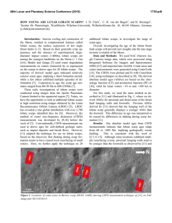
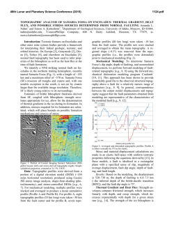
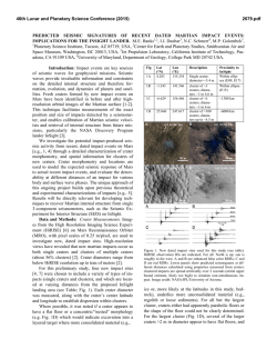
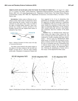
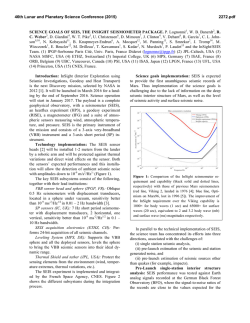
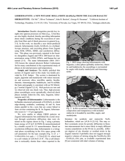
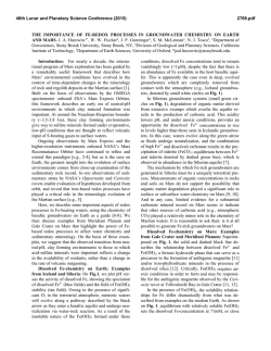
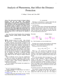
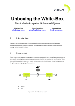
46th Lunar and Planetary Science Conference (2015)
1485.pdf
MASS WASTING IN PLANETARY ENVIRONMENTS: IMPLICATIONS FOR SEISMICITY. R. C. Weber,1 A. L. Nahm2, and N. Schmerr3, 1NASA Marshall Space Flight Center ([email protected]), 2University
of Idaho, 3University of Maryland.
Introduction: On Earth, mass wasting events such
as rock falls and landslides are well known consequences of seismically generated ground motion.
Through a variety of remote sensing techniques, tectonic faults have been positively identified on all four
of the inner planets, Earth’s Moon, several outer planet
satellites, and asteroids [1]. High-resolution imaging
has enabled positive identification of mass wasting
events on many of these bodies. On Mars, it has been
suggested that fallen boulders may be indicative of
paleomarsquakes [2]. On the Moon, impacts and
moonquakes have likewise been suggested as potential
triggering mechanisms for mass wasting [3]. Indeed,
we know from the Apollo era that the Moon experiences a wide variety of seismicity [4].
Seismicity estimates play an important role in creating regional geological characterizations, which are
useful for understanding a planet’s formation and evolution, and of key importance to site selection for landed missions. Here we investigate the regional effects of
seismicity in planetary environments with the goal of
determining whether surface features such as landslides and boulder trails on the Moon, Mars, and Mercury are triggered by fault motion (Fig. 1). We aim to
quantify the amount of near-source ground shaking
necessary to mobilize the material observed in various
instances of mass wasting.
Lobate scarps: Lobate scarps, the typical surface
expressions of thrust faults resulting from tectonic
compression, are widely observed on the Moon, Mars,
and Mercury (Fig. 2). Compared to other types of tectonic faults, surface-cutting thrust faults require the
largest amount of stress to form and/or slip, and thus
are expected to result in large quakes. While normal
faults, graben, and wrinkle ridges may be more abundant on Mars, the Moon, and Mercury respectively,
these structures would generate smaller theoretical
maximum quakes than lobate scarp thrust faults. Thus,
we optimize our chances of finding mass wasting associated with faults by studying lobate scarps.
Methodology: We first focus on calculating the
theoretical maximum quake that could occur as a result
of slip on a given fault and then determine the resulting
effects on the surrounding surface morphology. The
expected damage area indicated by seismic wavefield
modeling is compared to mapped imagery to determine
the likelihood of a quake having triggered a mass wasting event.
Fig. 1: (left) Landslide deposits (granular flow) on an interior slope of Marius crater on the Moon (11.9°N, -50.8°E).
(right) Boulder tracks emanating from a crater rim alcove
on Mars (-9.515°N, 16.433°E). A 74-km compressional
fault in the Arabia-Sabaea Terra is located <100km away.
Fig. 2: Examples of lobate scarps on the Moon (left), Mars
(center), and Mercury (right). Moon: Evershed S1 (center
lat/lon 33°N/197.1°E), Mars: Utopia Planitia #s 1801, 1802,
1804 (center lat/lon 52.9°N/119.2°E), Mercury: Beagle
Rupes (center lat/lon -3.5°N/100.7°E).
Theoretical maximum quake. Following the method outlined in [5], the theoretical maximum quake
magnitude is derived from basic fault properties. These
are either estimated from imagery or derived from laboratory rock experiments or elastic dislocation models, and include the length (L), fault dip angle (δ),
depth of faulting (T), and fault width (w) (Fig. 3). Fault
displacement (D) is calculated using displacementlength scaling such that D = γL, where γ is determined
by rock type and tectonic setting [6]. We note that subsurface fault geometry and mechanical properties of
planetary lithospheres and regoliths are not completely
understood, and thus represent potential sources of
uncertainty in the maximum quake calculation. To
incorporate this uncertainty, we investigate ranges in
fault parameters, placing upper and lower bounds on
46th Lunar and Planetary Science Conference (2015)
Fig. 3: Schematic 3-D (left) and cross-sectional (right)
views showing the fault parameters: displacement (D), dip
angle (δ), vertical relief, depth of faulting (T), and fault
width (w) for the thrust fault underlying a lobate scarp.
our maximum quake calculations rather than estimating discrete values.
The best measure of the size of a planetquake is the
seismic moment, M0. Seismic moment is calculated by
multiplying the shear modulus of the ruptured rock (G)
by the area of the ruptured portion of the fault (A) and
the average displacement (D) produced during the
quake, such that M0 = GAD = G(Lw)(γL) [5]. The
seismic moment represents the total energy consumed
in producing displacement on a fault, regardless of the
local strain rate or fault formation mechanism.
Seismic wavefield modeling. In order to determine
the dimensions of an area affected by seismic shaking,
we model the ground motion resulting from the theoretical maximum quake along a given fault (Fig. 4).
Following the method of [7], we use the Serpentine
Wave Propagation Program (WPP), a numerical code
for simulating seismic wave propagation through arbitrary elastic and anelastic media in a 3D model space
[8]. The initial model of a given fault includes regional
3D topography derived from digital elevation models,
and the planet’s relevant background 1D velocity.
We note that the modeled peak ground motion is
less strongly dependent upon the choice of background
velocity model than upon the scattering and attenuation
properties of the shallowest materials in the model.
Synthetic seismograms for the Moon most reasonably
approximating those recorded by the Apollo seismometers are acquired for a 1 km thick, highly scattering
layer as the topmost layer in the model. Similar highly
fractured layers are expected on Mars and Mercury,
and we approximate their velocities using the physical
properties of a basaltic crust for each body.
Mass Wasting Modeling: Peak vertical ground velocity (a proxy for displacement) occurs within a few
kilometers of the main shock and drops off rapidly
away from the source. Thus we should expect most of
the mass wasting phenomena to occur in the immediate
vicinity of the fault. However, this result may depend
on regional effects such as surface slope and
megaregolith thickness; a thicker megaregolith (as
might be expected in the vicinity of large craters)
would tend to focus shaking in some of the crater ba-
1485.pdf
Fig. 4: Predicted ground motion in the vicinity of the Evershed lobate scarp on the Moon. Left: Surface topography
input into the simulation, from the Lunar Orbiter Laser Altimeter experiment. The Evershed scarp is centered in the
image (see Fig. 2). Right: Ground motion for a magnitude
7.8 quake on a subjacent reverse fault, with T=2.25 km. The
surface trace of the scarp is indicated by the red line. A
random distribution of heterogeneity of 25% in seismic
wave velocity with 100 km scale length scatterers is placed
in the lunar megaregolith to simulate the scattering typically
present in lunar seismograms. Peak ground velocity is
measured for the first 1000 seconds of the seismic trace.
sins. The presence of sediments also enhances seismic
shaking; this could be relevant for Martian craters that
may have been lakes some time in the past.
We will compare the observed extent of mass wasting in the vicinity of a fault to the modeled event magnitude and peak ground motion in order to establish a
method to translate quake parameters into mass wasting estimates. This has been performed for terrestrial
examples focused on determining landslide area and
density over time in seismically active regions [9], as
well as using the presence or absence of precariously
perched boulders as indicators of the vigor of regional
seismic shaking. The latter example has also been performed on Mars, where both boulder size and boulder
trail density were found to peak close to the center of a
fault system and decrease linearly along strike [2]. We
expect to find systematic variations in fit parameter
estimates for each body, reflecting different gravitational strengths, regolith cohesion properties, and other
geologic settings local to each body/study region.
References: [1] Watters, T. R. and Schultz, R. A.
(2010) Cambridge University Press. [2] Roberts, G. P.
et al. (2012) JGR, 117, doi:10.1029/2011JE003816. [3]
Xiao, Z. et al. (2013) Earth Planet. Sci. Lett. 376, 1–
11. [4] Weber, R. C. (2014) Elsevier, 539–554. [5]
Nahm, A. L. and Velasco, A. A. (2013) LPSC 44th,
Abstract #1422. [6] Cowie, P. A. and Scholz, C. H.
(1992) J. Struct. Geol. 14, 1149–1156. [7] Schmerr, N,
et al. (2013) LPSC 44th, Abstract #2438. [8] Sjogreen,
B. and Petersson, N. A. (2012) J. Sci. Comp. 52, 17–
48. [9] Meunier, P. et al. (2007) GRL 23,
doi:10.1029/2007GL031337.

© Copyright 2026