
Unboxing the White-Box
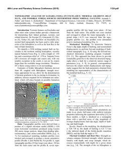
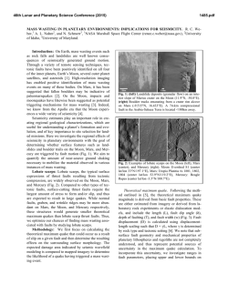
Unboxing the White-Box Practical attacks against Obfuscated Ciphers Eloi Sanfelix [email protected] 1 Cristofaro Mune [email protected] Job de Haas [email protected] Introduction The use of secret codes and ciphers for protecting information dates back to almost 4.000 years ago. Messages were encoded in different means for allowing two parties to communicate, without making the message content available to others. 1.1 Threat models Typical threat modeling applied in cryptography involves a malicious third party attempting to access either the keys used for protecting the content or the protected content itself. In this model, which we refer as the “BlackBox” model, the attacker is assumed to be able to observe and alter the ciphertext, without having access to the systems performing cryptographic operations. Figure 1.1 - Black-Box threat model In some cases the threat model is augmented with the attacker’s ability to interact with the systems performing the crypto operation, via observation and/or alteration of system parts and processes. We refer to this model as “Gray-Box” model, where the attacker has access to the system, but he is still not allowed to access the key and/or to tamper with the cryptographic algorithm and its implementation. Figure 1.2 - Gray-box threat model 1.2 White-box threat model The digitalization of goods and services has allowed the economy to transit to a new “Internet” era, where immaterial goods are digitalized and exchanged over the Internet. Examples are products for entertainment, such as music and movies, or the money itself, which is now available in a digital form and payments are performed by means of cryptographic processes based on delivered payment keys (see Figure 1.3). Figure 1.3 - Digital economy The digital nature of such goods and services allows for an infinite number of copies. For such a reason, the associated business models rely not so much in the availability of the good but in the authorization to actually use it. A user who has access to the goods, might not be able to “consume” the good unless authorized by the selling party. For instance: movies could not be watched without the proper key for decrypting the content, and payment could not be performed without the proper payment keys. It can be clear that, for this model to work, a user must be given access to the purchased goods but not the keys protecting the content. On the other hand, the user could be the attacker himself, having the interest and the motivation for obtaining wider and more extended access to the purchased goods, bypassing the security implemented. The Black-Box and Gray-Box threat models are insufficient for describing such a context. Both models rely on having two friendly parties communicating, while the attacker is none of the parties. In the described scenario, instead, the attacker can be one of the communicating parties, which must have limited and controlled access to the provided goods or service. This explains the need for a different threat model, shown in Figure 1.4, which we will refer to as “White-Box” model. Figure 1.4 - White-Box threat model In the White-Box threat model: • The attacker can observe the encryption process from within the system • The attacker can modify anything at will, including the cryptographic algorithm Achieving security within this model is very difficult, as the cryptographic keys used for protection are stored in the system and potentially available to the attacker. Protecting such keys becomes the fundamental security challenge and this is what white-box cryptography tries to achieve. 1.3 White-Box Cryptography White-box cryptography (WBC) aims at protecting the cryptographic secrets against an attacker with full access to the implementation (security in a white-box context). Thus, a white-box cryptographic implementation is designed to be resistant against attackers that can observe intermediate data during the computation, attackers that can modify such intermediate data and attackers that can manipulate execution of the cryptographic code. Additionally, it might be required for white-box cryptographic implementations to provide some degree of binding to a particular hardware platform such that an attacker cannot lift their code and execute it within other platforms. An introductory article to the topic of white-box cryptography can be found in [1]. The first WBC implementation has been described in 2002 by S. Chow et al. [2], which showed how it was possible to transform the implementation of a crypto algorithm into a key-dependent implementation. The execution of such transformed implementation performs the cryptographic operation with the given key, without exposing the key itself. The underlying idea of WBC is to merge the key and the crypto algorithm code into a new, transformed code. The key is effectively hidden in the code and cannot be easily separated. WBC implementation of symmetric block ciphers, like AES and DES, are available both in academic literature and as commercial products. Additionally, some WBC suppliers offer implementations of algorithms such as RSA and Elliptic Curve Cryptography. 1.3.1 WBC and Software Security The broad capabilities available to an attacker in the White-Box model are often addressed with countermeasures at multiple levels. WBC is one of these countermeasures, which addresses the problem of hiding the key. The abilities to inspect and modify the system at will are countered with anti-tampering mechanisms and program obfuscation. Device binding countermeasures are also used to avoid code lifting attacks and reuse of the implementation on other devices. . Figure 1.5 - WBC and Software Security Figure 1.5 provides an overview of the security countermeasures that can be found in practice, along with the WBC implementation. This work focuses on attacks to the WBC implementation. Additional countermeasures are hereby briefly described only for completeness. 1.3.1.1 Anti-tampering Anti-tampering mechanisms are introduced in order to prevent an attacker from modifying the application and analyzing its behavior under modification. For example, an anti-tampering mechanism could verify the integrity of the software at random time intervals, and detect modifications performed on the code or on static data. Anti-tampering mechanisms are thus meant to prevent modification of critical parts of the application (e.g. license checks) and introduction of instrumentation (breakpoints, function detours, etc.) into the application at runtime. Information on software anti-tampering mechanisms can be found in [3] and [4] 1.3.1.2 Program obfuscation Program obfuscation is designed to prevent reverse engineering or make the final software product significantly more difficult to understand for an attacker. To this end, techniques to obfuscate control flow and data are applied to the protected application. For example, a software protection suite may introduce bogus control flow transfers coupled with opaque predicates, in order to increase the complexity of the code. A good introduction to the topic of software obfuscation and reverse engineering of obfuscated code is provided in chapter 5 of [5]. 1.3.2 WBC implementation overview The typical WBC implementation relies on the usage of key-dependent lookup tables for computing the result of a cryptographic operation. In principle, given a cryptographic operation, where the algorithm C is executed with a given key K on input I for computing output O: C(I, K) = O A table T, dependent on the key K, can be created such that: C(I, K) = Tk(I) = O The table T can theoretically be constructed by enumerating all the possible output of the cryptographic operation C, when I span all the values of the possible input space. In the case of AES, where the block size is 128 bits, the table would have a size of 2 128 values of 128 bits each. It is obviously impractical to construct such a table, but the approach shows how it can be possible to perform a key-dependent cryptographic operation, while making the key not available for extraction. In practice the tables are constructed for performing smaller computation, whenever actual key material is used. The tables need to be recomputed every time the key needs to be modified. Figure 1.6 shows the example of a fixed-key implementation of WBC. Figure 1.6 - WBC generation 1.3.3 WBC construction The main operation to be performed when constructing a WBC implementation is to merge the given key with the algorithm. This is typically performed via a “partial evaluation” of the key, which pre-computes the effect of the key when applied within the crypto algorithm. Figure 1.7 shows an example of such partial evaluation. The S-Box of a given algorithm is re-computed for merging the key into the S-Boxes. The values of the new S-Box (T in the picture) are dependent on the actual key value. After the partial evaluation the key is not explicitly available within the system, and is now merged within the TBoxes. Figure 1.7 - WBC construction: partial evaluation Obviously, a partial evaluation alone is not sufficient for avoiding the recovery of the key. In fact, if the S-Box is known, the key can still be extracted via analysis of the T-Boxes. For such a reason, random bijections are also merged along with the key, creating an entirely different T’-box, which is dependent on the specific bijection used. -1 A bijection B is by definition invertible: an inverse function B exists, such that: -1 B*B =1 Where ‘*’ is used as the function composition operator and 1 is the identity operator. By merging a random bijection B along with the key, it is still possible to perform the desired operation, if the -1 input data is transformed accordingly, by using the inverse bijection B . When performing the operation, the -1 bijection B applied to the algorithm via the T’-box cancels out with the bijection B applied to the data. The operation yields the desired computed results unaffected by the specific bijection B selected. Figure 1.8 - Internal encodings: bijections Figure 1.8 shows the described process, where two different bijections are selected, one for decoding the input and a second one for encoding the output. If multiple T’-boxes are chained, it is easy to visualize that input decoding function is the inverse of the output encoding function of the previous T’-box. We refer to these random encoding functions as the internal encoding of the WBC. The internal encoding accounts for the random configuration data visible in Figure 1.6. The internal encoding allows the randomization of key-dependent data, making not possible to recover the key without knowing the actual encoding used. It is possible, in principle, to select one single random encoding for the entire function, but this could allow for an easier recovery of the encoding itself, and hence the key. 1.3.3.1 External encoding The internal encoding does not affect the result of the operation to be performed. The output O is provided in presence of the input I, regardless of the actual internal encoding selected. This means that the input I and the output O are not encoded and are identical to the input/output of the original crypto algorithm. By applying the same merging technique described in Section 1.3.3, it is possible, in principle, to also receive transformed input and provide transformed output, as shown in Figure 1.9. Figure 1.9 - External encoding The entire AES White-Box is enclosed between two additional random encodings. We refer to them as external encoding. External encoding is responsible for decoding the input from the sending process and supplying properly encoded output to the receiving process. This approach requires coordination of the sending and/or receiving processes, which have to manipulate input and/or output according to the encodings merged within the WBC implementation. Such requirement makes external encoding difficult to be used in practice. 1.3.4 Potential attacks In this section we provide an overview of some potential attacks to WBC implementations, as used in real-life systems. 1.3.4.1 Cloning or code lifting An attacker extracts parts of the protected application in order to execute them independently. For example, a white-boxed cryptographic implementation is lifted in order to create a cloned DRM client able to decrypt the content on a different device. 1.3.4.2 Key recovery attacks In white-box cryptographic (WBC) implementations an attacker cannot directly obtain the keys from memory. Instead, an attacker needs to locate the WBC implementation first, understand its structure (e.g. number of rounds, inputs and outputs, etc.) and then attempt to extract the key. In terms of key extraction from WBC implementations, well-known attacks can be categorized in the following main classes: Statistical analysis attacks: statistical attacks are based on observing the intermediate data used by a WBC implementation during its execution, and performing statistical analysis on it to retrieve information on the secret key. For this, an attacker typically observes the data at the outer rounds (i.e. first or last round) of the cryptographic algorithm and computes the relationship between the observed data and the data that an unprotected implementation would be computing. This class of attack is similar to side channel attacks as applied to hardware implementations of cryptographic algorithms. The statistical bucketing attack described in [2] is an example of such an attack. Data manipulation attacks: manipulating data at intermediate stages within the algorithm might allow for retrieving information on the secret key. Typically, an attacker modifies intermediate data towards the end of the algorithm (usually before the last round starts) and compares correct and incorrect results to learn information related to the key. This class of attack is similar to fault injection attacks as applied to hardware implementations of cryptographic algorithms. The attack described in [6] is an example of such an attack. Control flow manipulation attacks: it might be possible to obtain information on the key by altering the control flow during the execution of the WBC implementation. For example, in an RSA implementation based on a regular binary exponentiation algorithm, it is possible to determine the key by repeatedly skipping operations at the end of execution and observing changes to the output data [7]. This class of attack is similar to fault injection attacks as applied to hardware implementations of cryptographic algorithms. 1.3.5 Additional considerations Attacks have been published for all the academic WBC proposals. All the discussed attacks focus on key recovery on WBC. It has been shown that the knowledge of the type of applied transformations is sufficient for recovering the key. The concrete transformation applied and key are considered not to be known to an attacker. The requirement of knowing the transformation type is actually never met in real-life attacks against unknown WBC implementations. The attacker is often in front of an unknown and possibly heavily obfuscated target, where extracting information is difficult. 1.3.6 Our work Our work focuses on using hardware attack techniques, such as Side Channel Analysis and Fault injection, for attacking WBC implementation. We show how those techniques can be entirely applicable to software cryptographic implementations and can be ported in a natural way to the software domain. We show that this approach allows mounting practical attacks against WBC implementation. Finally, we show how this approach allows for a fast recovery of the key, with little or no requirement on the actual knowledge of the WBC itself. 2 Differential Fault Analysis on White Box Cryptography In this chapter we discuss a technique that can be used for key extraction on White Box Cryptography solutions, based on injecting faults into the cipher and analyzing their effects. 2.1 Differential Fault Analysis Differential Fault Analysis was first introduced in [8], which presented the attack we describe in section 2.1.1. The mechanics behind this type of attacks are as follows: 1. The attacker records correct and faulty outputs. In order to generate faulty outputs, the attacker introduces faults during the computation of the cryptographic algorithm, typically towards the end of its execution (e.g. before the final round). In the case of hardware solutions, this is typically done by altering the environmental conditions of the device. For example, voltage gltiching or laser fault injection could be used to introduce faults. 2. The attacker builds a model of the introduced faults, and performs an analysis of the collected outputs in order to determine the key. The location within the cryptographic algorithm in which faults are injected in step 1 and the analysis performed in step 2 above are closely related. These depend on the cryptographic algorithm under attack. Attacks for a number of algorithms can be found in the literature, including but not limited to DES, AES, RSA and several ECC algorithms. In the next sections we describe attacks on Triple DES and AES and discuss how to apply them to White-Box implementations. 2.1.1 DFA on Triple DES Figure 2.1 describes the final rounds of execution of a Triple DES encryption or decryption, where the F function is defined as shown in Figure 2.2. Each round of execution uses a 48 bit round key. The attack works by recovering one round key at a time, until the complete key can be computed. Figure 2.1 Final rounds of a DES encryption Figure 2.2 The DES Feistel function, F In order to recover the last round key (K16) using a DFA attack, the attacker injects faults during the execution of round 15. Using the correct and faulty output, we can write the following equations: R16 = F(R15 , K16) L15 R’16 = F(R’15 , K16) L15 In the above equations, the values of K16 and L15 are unknown. Combining these two equations, we obtain the following equation in which the only unknown is the round key K16: R16 R’16 = F(R15 , K16) F(R’15 , K16) From the F function we can see that DES uses 6 round key bits to compute 4 output bits in each round, making it possible to solve this equation in chunks of 6 bits of the round key. In particular, for each individual S-Box the following equation needs to be solved: (P (R16 R’16)))i = Si(E(R15)K16i) Si(E(R’15)K16i) -1 Where E and P represent the expansion and permutation steps of the F function, respectively. This equation can be easily solved by exhaustive search. Typically this results in a number of candidates for each affected sub-key for each fault. Therefore, an attacker needs to iterate this process until only one candidate remains for each key. However, in some cases, when the faults are not injected in the exact way as expected by the attack it is possible to discard a correct key. Therefore, we use a counting strategy instead of discarding key candidates instead: for each fault, we compute the set of solutions to the equation above and increase the count for the respective candidates. Once all faults are analyzed, the candidate with the highest count for each sub-key is selected as the correct candidate. An example output of such an attack on the last round is shown in the following listing, in which we display the results for the top 4 candidates for each sub-key: Processing round 16: Best result S-Box 1: 0, sub key: 25 (0x19), 1, sub key: 27 (0x1B), 2, sub key: 17 (0x11), 3, sub key: 24 (0x18), Best result S-Box 2: 0, sub key: 30 (0x1E), 1, sub key: 12 (0x0C), 2, sub key: 28 (0x1C), 3, sub key: 60 (0x3C), Best result S-Box 3: 0, sub key: 53 (0x35), 1, sub key: 42 (0x2A), 2, sub key: 56 (0x38), 3, sub key: 51 (0x33), Best result S-Box 4: 0, sub key: 48 (0x30), 1, sub key: 29 (0x1D), 2, sub key: 44 (0x2C), 3, sub key: 31 (0x1F), Best result S-Box 5: 0, sub key: 57 (0x39), 1, sub key: 56 (0x38), 2, sub key: 41 (0x29), 3, sub key: 40 (0x28), Best result S-Box 6: 0, sub key: 42 (0x2A), 1, sub key: 41 (0x29), 2, sub key: 45 (0x2D), 3, sub key: 33 (0x21), Best result S-Box 7: 0, sub key: 27 (0x1B), 1, sub key: 38 (0x26), 2, sub key: 39 (0x27), 3, sub key: 34 (0x22), Best result S-Box 8: value: value: value: value: 1.00000 0.43750 0.38890 0.33330 value: value: value: value: 1.00000 0.35290 0.33330 0.33330 value: value: value: value: 1.00000 0.47620 0.45450 0.41670 value: value: value: value: 1.00000 0.22220 0.21430 0.21430 value: value: value: value: 1.00000 0.36840 0.36840 0.35000 value: value: value: value: 1.00000 0.28000 0.25930 0.24140 value: value: value: value: 1.00000 0.29170 0.29170 0.25000 0, sub key: 12 (0x0C), 1, sub key: 28 (0x1C), 2, sub key: 21 (0x15), 3, sub key: 44 (0x2C), Round key: 65 ED 70 E6 value: value: value: value: A6 CC 1.00000 0.28570 0.27270 0.27270 The scores above are normalized to the top candidate for each sub-key. For example, for S-Box 8 the count for the second best candidate is 28.5% that of the top candidate (i.e. the top candidate was counted about 3 times more often than the last candidate). This gives a strong confidence in the success of the attack. Once the last round key is known, the attack can be iterated to the previous round key. For this, the attacker injects faults one round earlier and computes the output of the one but last round by using the recovered last round key. If a TDES cipher is being used, the same attack can be applied to the middle DES once the final DES key is known. Finally, if a TDES cipher with three keys is used, the attack can be iterated to the initial DES. 2.1.2 DFA on AES Several DFA attacks have been published for the AES cipher. In this whitepaper we describe the attack we implemented in our Inspector tool, which was introduced in [9]. Additional examples of DFA attacks on AES can be found in literature, e.g. in [10] [11]. We first describe the attack on AES128, and later discuss how to extend it to AES192 and AES256. For AES128, the final two rounds of the encryption process consist of the following operations: SubBytes ShiftRows MixColumns AddRoundKey (K10) SubBytes ShiftRows AddRoundKey (K11) Each of these operations is defined as follows: • SubBytes: Each byte in the AES state is transformed by applying the AES S-Box. • ShiftRows: The rows in the AES state are shifted to the left by 0, 1, 2 or 3 cells (row 1 to 4). • MixColumns: A matrix multiplication is applied, which results in applying a 32-bit transformation to each column of the state. Let's analyze how a one-byte fault introduced before the MixColumns in round 9 propagates to the output of the cipher. If the first byte of the state is altered from A to X, as shown in Figure 2.3, the fault will propagate to the complete first column after the MixColumns operation (see Figure 2.4). Figure 2.3 DFA on AES: one byte fault before MixColumns Figure 2.4 DFA on AES: byte fault propagation after MixColumns The next steps are simply performed byte-wise, and therefore we conclude that one faulty byte before the last MixColumns propagates into 4 faulty bytes at the output. The final values for these 4 faulty bytes would be as shown in Figure 2.5. Note that these bytes would not be located within the same column at the end of the AES computation due to the effect of the ShiftRows operation. Figure 2.5 DFA on AES: expressions for corrupted output bytes For the first faulty byte, we can write the following expressions: S(2A⊕3B⊕C⊕D⊕K10,0) ⊕ K11,0 = O0 S(2X⊕3B⊕C⊕D⊕K10,0) ⊕ K11,0 = O’0 And after XOR-ing them: S(2A⊕3B⊕C⊕D⊕K10,0)⊕ S(2X⊕3B⊕C⊕D⊕K10,0) = O0⊕ O’0 Similar expressions can be written for each of the faulty bytes, obtaining a set of 4 related equations. Just like in the attack for DES described above, the attack on AES involves solving these equations to obtain a sub-set of candidates for parts of the round key. In this case, each fault provides potential candidates for 4 bytes of the key. Repeating this process with different faults allows finding unique values for each sub-key. Repeating this process for the other columns of the AES state allows recovering candidates for all the sub-keys, and therefore leads to the last round key. For AES128, the last round key is enough to perform a reverse key schedule operation and retrieve the original AES key. For AES192 and AES256, two round keys need to be recovered in order to compute the full AES key. As mentioned earlier, the full detailed description of this attack can be found in [9]. 2.2 DFA attacks applied to WBC In order to apply DFA attacks to a WBC implementation, one fundamental requirement needs to be satisfied: the output of the WBC needs to be available in a non-encoded form. Once this requirement is satisfied, the attack requires the ability to inject faults into the cryptographic process at the right locations within the algorithm. in order to locate the appropriate location in which faults need to be injected we typically combine static and dynamic code analysis. For example, recording execution and memory access traces and visualizing them can highlight the location of the target cryptographic algorithm and its rounds. This can be seen in Figure 2.6, which shows the memory accesses performed by an obfuscated DES cipher on the stack. We can clearly see the execution of 16 rounds, and therefore we are able to determine at which time and in which memory region faults need to be introduced. More insights into applying these types of techniques to obfuscated code can be found in [12] [13]. Figure 2.6 Stack accesses during exection of wbDES challenge from www.whiteboxcrypto.com Additionally, randomly injecting faults during the computation and observing the output of the cryptographic algorithm can be used to determine the correct location. For example, injecting bit faults in early rounds of a DES execution will result in a fully randomized output. Injecting bit faults during the computation of the last round (i.e. too late for the attack described in section 2.1.1) will result in changes to the left half, but not the right half. Similarly, for the AES cipher, injecting one-byte faults at the location expected by the attack described in section 2.1.2 will result in 4 corrupted bytes. The location of the 4 corrupted bytes must follow a specific pattern, as indicated by the MixColumns and ShiftRows combination. Finally, injecting faults can be as simple as flipping bits of the DES or AES intermediate results during the execution of the algorithms. To this end, we can use several techniques: • If the code can be easily lifted to a high level language (e.g. C), we can introduce code to inject random faults at the right locations within the algorithm. • If the code can be run under a DBI framework (PIN, Valgrind, etc.) we can instrument the code to the inject faults and collect the output data. • A scriptable debugger (e.g. vtrace, gdb) can also be used. To this end, we can write debugger scripts to automate the execution of the cipher, injection of faults and collect the output data. • Alternatively, emulator-based setups can be used. For example, we've used the PANDA framework and the Unicorn Engine to attack WBC implementations. We provide an example using Unicorn Engine to inject faults on the Wyseur challenge in section A.1. Once the right location is found and a way to inject faults is implemented, performing the attack is just a matter of collecting enough output pairs and plugging them into the appropriate DFA algorithm. 3 Side Channel Analysis on White Box Cryptography This chapter discusses the implementation and effectiveness of Side Channel Analysis (SCA) on White Box Cryptography (WBC) solutions as described in chapter 0. First we give some background of differential attacks and then we show how WBC implementations can be attacked using such differential SCA. 3.1 Side Channel Analysis and DPA The fact that "side channels" can leak sensitive information has understood for a long time. In the mid-nineties it became clear that side channels such as timing or power are also a threat to embedded cryptographic keys. Kocher [14] showed that by applying a technique called Differential Power Analysis (DPA) keys could be broken even in very noisy environments. The principle of differential side channel analysis can be described as: Validating predictions by applying statistical methods to the observed and predicted behavior of a system. In the case of cryptography the predictions are centered on the secret key. Within cryptographic algorithms the secret key is not used as a whole, but rather in computational and logical units of much smaller size than the total key length. This allows predictions to focus on small parts of the key at a time, in a so-called divide and conquer attack. A DPA attack can be summarized in the following steps: 1. Choosing an intermediate result: the DPA attack targets an intermediate result of the algorithm, such as the output of the S-Boxes of the first round for DES or AES ciphers. These intermediate results typically depend on a small part of the key, such that a divide and conquer strategy can be applied. 2. Performing measurements: Acquire a set of traces while the device is performing an encryption or decryption operation with random inputs. In the case of DPA, this results in a set of power traces and their corresponding plaintext/ciphertext pairs. 3. Calculating hypothetical intermediate values: For each input value, all possible values of the target intermediate result are computed. For example, in the case of DES this would result in 64 values for each S-Box output. 4. Comparing intermediate values to measurements: As a final step, the hypothetical intermediate values are compared to the measurement set in order to find the most likely key. This is typically done by applying statistical techniques such as the difference of means or the correlation coefficient. Many such statistical techniques (also known as distinguishers) have been researched by the cryptographic hardware security community. To visualize the above statements, consider a group of measurements each taken for a different random input. These can be grouped on any arbitrary intermediate result in order to apply a statistical distinguisher. A simple example is a bit of the input, but it might also be any predicted intermediate value. Group by known data 0 Subtract 0 0 1 Average trace 0 1 1 1 Differential trace Figure 3.1 Principle of difference of means As a simple statistical test we apply a difference of means as shown in Figure 3.1. Subtraction of two means provides indication in the resulting difference where and if there is evidence of the bit being processed. The next step is translating this same method to the prediction of a value of part of the secret key. As shown in Figure 3.2, given the known input and a possible value for a 6-bit sub-key of the DES secret key we can perform the same test for one bit of the S-Box output. This allows testing only 64 possible candidates of which one is expected to show a significant difference in case of leakage. Repeating this for all 8 sub-keys yields the full round key. In case of DES 2 round keys are required to recover the original full key. The second round key can be discovered by using the recovered first round key to predict intermediate values in the second round. For AES-128 it is sufficient to guess 8 times an 8 bit sub-key for a full 16 byte key. L K 1 1 Figure 3.2 DES Feistel function with a 6-bit sub key 3.2 SCA attacks applied to WBC Applying side channel attacks to a WBC implementation requires that measurements are taken during the execution runtime of the implementation. There are two items to be determined: 1. What to measure 2. How to achieve the measurement For the first item we have many choices. What we want to capture are the values that are computed during the execution of the WBC. A simple way this can be achieved is by capturing any writes to memory. Of course this might miss certain values that are only kept in registers. Capturing register updates achieves a better coverage, but it may lead to very large datasets. Another alternative is to snapshot the memory areas that are updated during the execution. We found that capturing the stack space for every round of a crypto algorithm can achieve very good results and is relatively simple. Another source of leakage may be the lower bits of the read accesses as they reflect the index into the table lookups. For additional insights in options for information sources, [13] describes similar work to what we describe in this chapter and [15] introduces SLEAK, a simulator-based setup to analyze non-white-box cryptographic implementations. For the second item we have to consider how to obtain the data we are interested in. Again we have many options at our disposal. The best method is very dependent on the WBC implementation and the additional software protection mechanisms in place. These are methods we have employed during the analysis of different implementations: Hooking by library and code injection (eg. LD_PRELOAD or ptrace) Debugger scripting (GDB, vtrace) Binary instrumentation (PIN, Valgrind) (Source) Code lifting and modification (Hex-rays, python decompiler) Emulator recording (QEMU, unicorn) We provide an example of recording side channel traces on the Wyseur challenge using Unicorn Engine in section A.2. 4 Experimental results In this chapter we discuss experimental results obtained while analyzing openly available WBC implementations. 4.1 Analyzed WBC implementations For the sake of comparison, we analyze the same implementations as analyzed in [13]: • Wyseur challenge: this implementation was presented as a challenge by Brecht Wyseur on his website www.whiteboxcrypto.com. The challenge provides a white-box implementation of DES with naked inputs and outputs (i.e. no external encodings), compiled as an ELF for Linux/x86. • Hack.lu 2009 challenge: this implementation was presented as a challenge at Hack.lu 2009. The challenge provides a Windows executable with a white-box implementation of AES. • SSTIC 2012 Challenge: this implementation was presented as a challenge at SSTIC 2012. The challenge contains a white-box implementation of DES in Python bytecode. • ph4r05 white-box: this is a generator for white-box AES implementations available on GitHub. The code supports implementations with and without external encodings. We analyze the version without external encodings only. In addition to these openly available implementations, we have found a number of commercial implementations to be vulnerable to the techniques covered in this paper while performing security assessments on them. 4.2 SCA Attack results For the SCA attacks, we run key extraction attacks against the same implementations as analyzed in [13]. The findings are summarized in Table 4-1. Table 4-1 Results of applying Side Channel Analysis to WBC implementations Implementation Fault injection Results Wyseur (DES) PIN instrumentation 60 Hack.lu 2009 Unicorn instrumentation 16 (AES) Implementation SSTIC 2012 Fault injection Results Modified lifted python code 16 PIN instrumentation 2000* N/A Not broken – encoding makes DFA (DES) Karroumi (AES) NSC 2013 (encoded AES) not feasible Our results match the results described in [13], except for the Karroumi implementation. In this case, we required more traces and manual intervention in order to properly retrieve the key. In particular, different generations of the WBC seem to provide leakage results. As a result, we needed to extract different parts of the keys with attacks targeting different intermediate values (S-Box output and 8 multiplicative inverse in GF(2 )). 4.3 DFA Attack results Table 4-2 provides the results of the DFA attacks we implemented, as well as the way in which we implemented the attacks. Table 4-2 Results of applying Differential Fault Analysis to WBC implementations Implementation Fault injection Results Wyseur (DES) Unicorn emulator script Broken in 40 faults Hack.lu 2009 Debugging script (vtrace) Broken in 90 faults Modified lifted code Broken in 60 faults Modified source code Broken in 80 faults N/A Not broken – encoding makes DFA (AES) SSTIC 2012 (DES) Karroumi (AES) NSC 2013 (encoded AES) not feasible As can be observed, we were able to extract the keys for all the implementations analyzed in [13] also using DFA attacks. 4.4 Result analysis and comparison For those implementations without internal encodings, the number of executions required for DPA attacks is much lower than for DFA attacks. This is due to the fact that without internal encodings, there is a direct relationship between the hypothesis used by the DPA attack and the recorded data. In contrast, for those implementations with stronger internal encodings the number of executions required for DFA attacks is lower than for DPA attacks. Note however that the execution of these attacks once the measurement setup is ready can be repeated in a matter of minutes. Therefore, the number of traces is not really a limiting factor here, but rather the ability to instrument the WBC implementation and collect the right data. 5 Countermeasures As noted earlier, general software protection techniques such as code obfuscation, anti-tampering, antianalysis, etc. can be used to make these attacks more difficult. We also note that adding external encodings prevents the direct application of the attacks we discussed. However, in many scenarios (e.g. payment systems) it is not possible to apply external encodings in practice. We elaborate further on this topic in section 5.1. In this chapter we discuss specific countermeasures against the attacks introduced in sections 20 and 12 in order to strengthen the robustness of the WBC implementation in case the generic countermeasures are bypassed. 5.1 Use of external encodings External encodings are encodings applied at the input and/or output of the cipher. In this way, the cipher is -1 converted from a standard cipher (e.g. AES) into a cipher that computes G(AES(F (input), key)), where F represents the input encoding and G represents the output encoding. Both input and output encodings are assumed unknown to the attacker. In such a circumstance, DPA-like attacks cannot be directly applied because the attacker is not able to predict the intermediate values processed by the cipher implementation. Therefore, key hypothesis cannot be tested using statistical analysis and the cipher is protected against standard DPA-like attacks. Similarly, if output encoding is present, an attacker cannot observe the exact effect of faults introduced in the execution of the cipher. Therefore, DFA attacks on encoded outputs are not feasible either. However, external encodings turn the cipher into a non-standard algorithm that depends on the encodings. This is fine in cases where the output of the cipher is consumed by an entity that has knowledge of the encodings (e.g. another white-box cipher integrated in the same application) or when the complete end to end system is aware of the encoding scheme used. In practice, this is not always the case. The following situations illustrate this: • Different suppliers might provide different components, for example the licensing server and the client application in a DRM scheme. • Protocols might mandate the use of non-encoded inputs or outputs. For example, in EMV transactions the application cryptogram is expected to be the output of an ISO9797 method 3 Message Authentication Code using the DES cipher. Even in cases where the recipient of the cipher output is aware of the encoding, if this process is also available to the attacker it might still be possible to revert the encoding. Additionally, there have been examples of attacks that can work even in the presence of output encoding in literature [16] [17]. Therefore, we do not recommend relying on output encodings alone, but also implementing specific countermeasures against the attacks described in this document. 5.2 Countermeasures against DFA Countermeasures against DFA attacks usually involve some sort of redundant computation. For example, a device could perform the encryption process twice and compare its output. Assuming that the adversary does not have any access to the intermediate data, it is possible to detect the attack and prevent outputting faulty results. However, in the white-box settings this direct approach is not valid: if the attacker is able to observe the comparison of the two results, he can simply duplicate the faulty result and bypass the check. In order to protect a WBC implementation against DFA, the following two avenues might be used: • Carrying redundant data (e.g. checksums) along with the computation in such a way that a modification performed by an attacker can be detected, without transforming the data into a non-encoded domain. • Implementing the internal data encodings in such a way that faults propagate into bigger parts of the cipher state. In this way, the fault models expected by the standard DFA attacks do not apply and therefore an attacker would have to develop customized attacks. However, there is a lack of research into DFA countermeasures in this space, and the above ideas have not been extensively tested nor verified. 5.3 Countermeasures against DPA DPA attacks are well known in the hardware security community. Significant research effort has been spent in developing and analyzing countermeasures against this class of attacks in the last 15 years. However, these countermeasures are typically developed with assumptions that are not valid in the white-box context. Namely: • It is assumed that a good source of random numbers is available. In a white-box setting, the attacker is under full control of the environment and can thus prevent the generation of random numbers. • It is assumed that secret values computed during the execution of the cryptographic algorithm are not available to the adversary. However, it might be very well possible to adapt some of the ideas from the DPA research community to protect WBC implementations. First, balanced encoding schemes could be research in order to prevent attacks like DPA. Second, as suggested in [13], carefully designed schemes based on secret sharing and masking the intermediate data based on the input data could be used. Since DPA attacks require random input, tweaking the intermediate data encoding based on the input data might provide sufficient protection against these attacks. 6 Conclusions In this document we have introduced two classes of practical attacks on White-Box Cryptography implementations: Differential Fault Analysis attacks and attacks related to Differential Power Analysis. Our results show that standard WBC implementations can be attacked using these generic attacks borrowed from the cryptographic hardware space in a very efficient manner. Our attacks can even be applied with very little knowledge about the WBC implementation and limited reverse engineering effort provided that it is possible to instrument the target application. This brings us to the following questions: Is WBC utterly broken or useless? Can we still rely on WBC in practice? Or is this the final nail in the WBC coffin? In our opinion, these results highlight the need to consider gray-box attacks such as the ones we presented while designing and implementing White-Box Cryptography. Our experiences also show that it is important to test for these attacks in practice, as often the complexity of the WBC generation and software protection tooling results in overlooking unintentional leakage in the final implementation. Despite these results, we want to stress that using WBC implementations to protect cryptographic keys is still better than using vanilla cipher implementations. If a vanilla implementation is used, an attacker can simply extract the key from memory. When a WBC implementation is used, an attacker is forced into the realm of more specialized cryptographic attacks such as the ones we have discussed. Additionally, if protection mechanisms are implemented to make reverse engineering and instrumentation of the product more difficult, the time required for an attack is significantly increased. In our experience, a fully protected application can increase the attack window by 2 to 4 weeks. Combined with fast renewability of the software, short key lifetimes and risk mitigation measures in back-end systems, WBC technology could provide sufficient protection for a number of applications. Protection of single use payment keys for low value transactions or protection of live video content such as sports finals are examples of such potential applications. 7 References [1] B. Wyseur, WHITE-BOX CRYPTOGRAPHY: HIDING KEYS IN SOFTWARE http://whiteboxcrypto.com/files/2012_misc.pdf, 2012. [2] S. Chow, P. Eisen, H. Johnson and P. v. Oorschot, A White-Box DES Implementation for DRM Applications. [3] P. v. Oorschot, Revisiting Software Protection - http://people.scs.carleton.ca/~paulv/papers/isc5.pdf. [4] C. D. Chaboya, State of the Practice of Software Anti-Tamper, IEEE STC, 2007. [5] B. Dang, A. Gazet, E. Bachaalany and S. Josse, Practical Reverse Engineering: x86, x64, ARM, Windows Kernel, Reversing Tools, and Obfuscation, Wiley, 2014. [6] M. Jacob, D. Boneh and E. Felten, Attacking an obfuscated cipher by injecting faults. [7] J.-M. Schmidt and M. Medwed, Active Implementation Attacks - http://www.a-sit.at/pdfs/DFA-Report2.pdf, 2009. [8] E. Biham and A. Shamir, Differential fault analysis of secret key cryptosystems, Advances in Cryptology— CRYPTO'97, Springer, 1997. [9] P. Dusart, G. Letournex and O. Vivolo, Differential fault analysis on AES, Springer, 2003. [10] M. Tunstall, M. Debdeep and A. Subidh, Differential fault analysis of the advanced encryption standard using a single fault, Springer, 2011. [11] C. H. Kim and J.-J. Quisquater, New differential fault analysis on AES key schedule: two faults are enough., Springer, 2008. [12] F. Scrinzi, Behavioral analysis of obfuscated code, Univeristy of Twente, 2015. [13] J. W. Bos, C. Hubain, W. Michiels and P. Teuwen, Differential Computation Analysis: Hiding your WhiteBox Designs is Not Enough, 2015. [14] P. Kocher, J. Jaffe and B. Jun, Differential Power Analysis, 1999. [15] D. Walters, A. Hagen and E. Kedaigle, SLEAK: A Side-channel Leakage Evaluator and Analysis Kit, 2014. [16] B. Wyseur, W. Michiels, P. Gorissen and B. Preneel, Cryptanalysis of White-Box DES Implementations with Arbitrary External Encodings, 2007. [17] B. Olivier, H. Gilbert and C. Ech-Chatbi, Cryptanalysis of a White Box AES Implementation, Selected Areas in Cryptography, 2004. A Code snippets In this appendix we provide example code snippets to instrument applications using Unicorn for DFA and DPA attacks. A.1 DFA example script The following Unicorn script can be used to collect data for a DFA attack on the wbDES challenge. The script produces a log file (faults.txt) with plaintext and ciphertext on each line. The first plaintext and ciphertext pair is always performed without injecting any fault, and is thus the reference output for the DFA attack. from unicorn import * from unicorn.x86_const import * import struct import sys import random from elftools.elf.elffile import ELFFile def p32(x): return struct.pack("<I", x) def u32(x): if len(x) != 4: x = x + "\x00"*(4-len(x)) return struct.unpack("<I", x)[0] def p16(x): struct.pack("<H", x) def pack(x, size): if size == 1: return chr(x) elif size == 2: return p16(x) else: return p32(x) # Stack initialization data STACK = 0xbfff0000 STACK_SIZE = 0x10000 SP = STACK + STACK_SIZE - 0x800 RET = STACK PAGE_SIZE = 0x1000 output = [] evtId = 0 fault = True def should_fault(evtId, targetId, fault, address, size): return evtId > targetId and fault and address > STACK and address < STACK + STACK_SIZE and size == 1 def hook_mem_access_fault(uc, access, address, size, value, user_data): global output, evtId, fault evtId += 1 pc = uc.reg_read(UC_X86_REG_EIP) targetId = user_data[0] if access == UC_MEM_READ: value = u32(uc.mem_read(address, size)) if should_fault(evtId, targetId, fault, address, size): print "FAULTING AT ", targetId # Already faulted this time fault = False # Random bit in this event bitfault = 1 << random.randint(0, size*8 -1) uc.mem_write(address, pack(value ^ bitfault, size)) # At this PC the pushes a byte of output to the stack if pc == 0x08049e4f: output.append(value) def randstr(sz): x = open("/dev/urandom") rnd = x.read(sz) x.close() return rnd KEY16_ATTACK_START = 46000 KEY16_ATTACK_END = 49000 KEY15_ATTACK_START = 42000 KEY15_ATTACK_END = 46000 def main(): global output, fault, evtId # Get unicode in 32-bit x86 mode mu = Uc(UC_ARCH_X86, UC_MODE_32) fd = open("faults.txt", "wb") target = [0] # Hook mem read and write mu.hook_add(UC_HOOK_MEM_READ | UC_HOOK_MEM_WRITE , hook_mem_access_fault, user_data=target) # Map the full PE into unicorn elf = ELFFile(open("./wbDES")) for seg in elf.iter_segments(): if seg.header.p_type == "PT_LOAD": # LOAD this data = seg.data() mapsz = PAGE_SIZE*((len(data) + PAGE_SIZE)/PAGE_SIZE) addr = seg.header.p_vaddr - (seg.header.p_vaddr % PAGE_SIZE) mu.mem_map(addr, mapsz) mu.mem_write(seg.header.p_vaddr, data) entry = 0x80484C4 # Our main function, from IDA # Map zero page and a bit more, this should keep gs happy? mu.mem_map(0, 0x10000) mu.mem_map(STACK, STACK_SIZE) num_samples = 1 data_bytes = 16 for tracenum in xrange(100): target[0] = random.randint(KEY15_ATTACK_START,KEY16_ATTACK_END) fault = True evtId = 0 # set esp and ebp to their initial values mu.reg_write(UC_X86_REG_ESP, SP) mu.reg_write(UC_X86_REG_EBP, SP) # Write params on stack, and create stack frame for the call # plaintext = randstr(8) plaintext = "\x00"*8 start = 0x100 mu.mem_write(SP+start, "./wbDES\x00") argv = [SP+start] start += 10 for i in xrange(len(plaintext)): argv.append(SP+start) mu.mem_write(SP+start, "%.2x\x00" % ord(plaintext[i])) start += 5 # Now we need to place argv somewhere i = 0 for arg in argv: mu.mem_write(SP+0x200 + i*4, p32(arg)) i += 1 # And NULL mu.mem_write(SP+0x200+i*4, p32(0)) # And now main's return address and parameters mu.mem_write(SP+0x0, p32(RET)) # Return address @ sp mu.mem_write(SP+0x04, p32(len(argv))) # argc mu.mem_write(SP+0x08, p32(SP + 0x200)) # argv # Patch printf and putchar .plt --> return mu.mem_write(0x80483BC, "\xc3") mu.mem_write(0x80483EC, "\xc3") output = [] try: # And now run the emulator until we hits our RET if tracenum == 0: fault = False mu.emu_start(entry, RET) ciphertext = "".join(map(chr, output)) fd.write((plaintext.encode("hex") + ciphertext.encode("hex")) + "\n") print "FINISHED ", tracenum except: print "ERROR" pass if __name__ == '__main__': main() A.2 DPA example script The following Unicorn script can be used to collect data for a DPA-like attack on the wbDES challenge. The script produces two files: traces.bin contains the traced data, while data.bin contains the input and output of the DES operation. from unicorn import * from unicorn.x86_const import * import struct import sys import random from elftools.elf.elffile import ELFFile def p32(x): return struct.pack("<I", x) def u32(x): if len(x) != 4: x = x + "\x00"*(4-len(x)) return struct.unpack("<I", x)[0] def p16(x): struct.pack("<H", x) def pack(x, size): if size == 1: return chr(x) elif size == 2: return p16(x) else: return p32(x) # Stack initialization data STACK = 0xbfff0000 STACK_SIZE = 0x10000 SP = STACK + STACK_SIZE - 0x800 RET = STACK PAGE_SIZE = 0x1000 output = [] evtId = 0 def hook_mem_access_dpa(uc, access, address, size, value, user_data): fd = user_data if access == UC_MEM_WRITE and size == 1: # For writes we keep the data only d = p32(value) fd.write(d[:size]) # Uncomment this if you also want to record read addresses and data # elif access == UC_MEM_READ: # For reads we keep the lowest byte of the address + the data # Let's try a fault here # fd.write(chr(address & 0xFF)) # fd.write(uc.mem_read(address, size)) # And get the output pc = uc.reg_read(UC_X86_REG_EIP) if pc == 0x08049e4f: output.append(value) def randstr(sz): x = open("/dev/urandom") rnd = x.read(sz) x.close() return rnd def main(): global output, fault, evtId # Get unicode in 32-bit x86 mode mu = Uc(UC_ARCH_X86, UC_MODE_32) # open the trace data files fd = open("traces.bin", "wb") fd2 = open("data.bin", "wb") # Hook mem read and write mu.hook_add(UC_HOOK_MEM_READ | UC_HOOK_MEM_WRITE , hook_mem_access_dpa, user_data=fd) # Map the full PE into unicorn elf = ELFFile(open("./wbDES")) for seg in elf.iter_segments(): if seg.header.p_type == "PT_LOAD": # LOAD this data = seg.data() mapsz = PAGE_SIZE*((len(data) + PAGE_SIZE)/PAGE_SIZE) addr = seg.header.p_vaddr - (seg.header.p_vaddr % PAGE_SIZE) mu.mem_map(addr, mapsz) mu.mem_write(seg.header.p_vaddr, data) entry = 0x80484C4 # Our main function, from IDA # Map zero page and a bit more, this should keep gs happy? mu.mem_map(0, 0x10000) mu.mem_map(STACK, STACK_SIZE) prevSize = 0 for tracenum in xrange(150): evtId = 0 # set esp and ebp to their initial values mu.reg_write(UC_X86_REG_ESP, SP) mu.reg_write(UC_X86_REG_EBP, SP) # initialize random input data plaintext = randstr(8) # Write params on stack, and create stack frame for the call start = 0x100 mu.mem_write(SP+start, "./wbDES\x00") argv = [SP+start] start += 10 for i in xrange(len(plaintext)): argv.append(SP+start) mu.mem_write(SP+start, "%.2x\x00" % ord(plaintext[i])) start += 5 # Now we need to place argv somewhere i = 0 for arg in argv: mu.mem_write(SP+0x200 + i*4, p32(arg)) i += 1 # And NULL mu.mem_write(SP+0x200+i*4, p32(0)) # And now main's return address and parameters mu.mem_write(SP+0x0, p32(RET)) # Return address @ sp mu.mem_write(SP+0x04, p32(len(argv))) # argc mu.mem_write(SP+0x08, p32(SP + 0x200)) # argv # Patch printf and putchar .plt --> return mu.mem_write(0x80483BC, "\xc3") mu.mem_write(0x80483EC, "\xc3") output = [] try: # And now run the emulator until we hits our RET mu.emu_start(entry, RET) # capture the output data ciphertext = "".join(map(chr, output)) data_array = map(ord, str(plaintext + ciphertext)) print "TRACE " , tracenum, ":", str(plaintext).encode("hex") , " --> ", str(ciphertext).encode("hex"), # print the number of samples used for importing fd2.write(str(plaintext + ciphertext)) currSize = fd.tell() traceSize = currSize - prevSize prevSize = currSize print ", samples: ", traceSize except: print "ERROR" pass fd.close() fd2.close() if __name__ == '__main__': main()


© Copyright 2026