
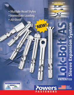
• Quick-Cure Vinylester Anchoring Adhesive • New Easy Dispensing
• Quick-Cure
Vinylester
Anchoring
Adhesive
• New Easy
Dispensing
Formula
• Free Quik-Flow
Nozzle Included
AC50 Silver
™
Adhesive Anchoring System
PRODUCT DESCRIPTION
The AC50 Silver is a two-component adhesive anchoring system. The
system includes injection adhesive in plastic cartridges, mixing nozzles,
dispensing tools and hole cleaning equipment. The AC50 Silver is designed
for bonding threaded rod and reinforcing bar hardware into drilled holes in
solid concrete base materials.
GENERAL Applications AND Uses • Bonding threaded rod and reinforcing bar into hardened concrete
• Evaluated for installation and use in dry holes
• Can be installed in a range of base material temperatures
FEATURES AND Benefits
•D
esigned for use with threaded rod & reinforcing bar hardware elements
• Cartridge design allows for multiple uses using extra mixing nozzles
• Mixing nozzles proportion adhesive and provide simple delivery method
into drilled holes
• Evaluated and recognized for long term and short term loading
(see performance tables for applicable temperature ranges)
APPROVALS AND LISTINGS
Conforms to requirements of ASTM C 881, Types I, II, IV and V, Grade 3,
Classes A & B (also meets Type III except for elongation)
Department of Transportation listings – see www.powers.com or contact
transportation agency
Guide specifications
CSI Divisions: 03 16 00- Concrete Anchors and 05 05 19 - Post-Installed
Concrete. Adhesive anchoring system shall be AC50 Silver as supplied by
Powers Fasteners, Inc., Towson, MD. Anchors shall be installed in accordance
with published instructions and requirements of the Authority Having Jurisdiction.
PACKAGING Dual (side-by-side) Cartridge:
28 fl. oz. (825 mL)
10:1 mix ratio
Storage life & conditions
Fifteen months in a dry, dark environment with
temperature ranging from 32˚F to 86˚F (0˚C to 30˚C)
Anchor
size range (typ.) 3/8" to 1" diameter threaded rod;
No. 3 to No. 8 reinforcing bar (rebar)
suitable base materials
Normal-weight concrete
2
AC50 Silver
™
INSTALLATION SPECIFICATIONS
Installation Specifications for Threaded Rod and Reinforcing Bar
Dimension/Property
Notation
Units
Threaded Rod
-
-
3/8"
1/2"
5/8"
3/4"
Reinforcing Bar
-
-
#3
#4
#5
#6
#8
d
in.
(mm)
Nominal diameter of drilled hole
do,(dbit)
in.
Minimum embedment
hef,min
0.625
(15.9)
3/4
ANSI
3-1/8
(79)
0.750
(19.1)
7/8
ANSI
3-1/2
(89)
0.875
(22.2)
1-1/8
ANSI
4
(102)
Nominal anchor diameter
Minimum concrete member thickness
hmin
Minimum spacing distance
smin
Minimum edge distance
cmin
Critical edge distance
cac
Tmax
ft.- lbs.
(N-m)
Effective cross sectional area of threaded rod
Ase
Effective cross sectional area of
reinforcing bar
Ase
in.2
(mm2)
in.2
(mm2)
A36 or F1554 Grade 36
F593 Condition CW stainless steel rod or
ASTM A193 Grade B7 carbon steel rod
Detail of Steel Hardware Elements
used with Injection Adhesive System
do ,(dbit )
0.375
0.500
(9.5)
(12.7)
7/16
9/16
ANSI
ANSI
2-3/8
2-3/4
(60)
(70)
hef + 1-1/4
(hef + 30)
1-7/8
2-1/2
(48)
(64)
1-7/8
2-1/2
(48)
(64)
in.
(mm)
in.
(mm)
in.
(mm)
in.
(mm)
in.
(mm)
Maximum torque
(only possible
after full cure
time of adhesive)
Threaded Rod
or Rebar
Nominal Anchor Size
1"
hef + 2 do
3-1/8
(79)
3-1/8
(79)
3-3/4
(95)
3-3/4
(95)
5
(127)
5
(127)
90
(122)
105
(142)
0.335
(216)
0.440
(284)
165
(224)
165
(224)
0.606
(391)
0.790
(510)
2hef
10
(13)
15
(20)
0.078
(50)
0.110
(71)
25
(34)
33
(45)
0.142
(92)
0.200
(129)
50
(68)
60
(81)
0.226
(146)
0.310
(200)
Threaded Rod and Deformed Reinforcing Bar Material Properties
Steel Description
(General)
Steel Specification
Nominal Anchor Size
(inch)
Minimum Yield
Strength,
fy (ksi)
Carbon rod
A 36 or F 1554
and Grade 36
3/8 through 1-1/4
36.0
58.0
Stainless rod
(Alloy 304 / 316)
F 593,
Condition CW
3/8 through 5/8
65.0
100.0
3/4 through 1
45.0
85.0
High strength
carbon rod
A 193, Grade B7
3/8 through 1
105.0
125.0
Grade 60
reinforcing bar
A 615, A706,
A 767, or A 996
3/8 through 1
(#3 through #8)
60.0
90.0
Grade 40
reinforcing bar
A 615
3/8 through 3/4
(#3 through #6)
40.0
70.0
(ASTM)
Minimum Ultimate
Strength,
fu (ksi)
3
AC50 Silver
™
INSTALLATION Instructions for solid base materials
Gel (working) Time and Curing Table
Temperature of
Base Material
˚F
˚C
5
14
23
32
41
60
68
86
95
-15
-10
-5
0
5
15
20
30
35
Gel
(Working)
Time
Full
Curing
Time
120 minutes
90 minutes
90 minutes
45 minutes
35 minutes
15 minutes
8 minutes
4 minutes
3 minutes
48 hours
24 hours
14 hours
7 hours
4 hours
3 hours
90 minutes
60 minutes
45 minutes
For installations in base material temperature between 5˚F and 32˚F the cartridge
temperature must be conditioned to between 68˚F and 95˚F (20˚C - 35˚C).
Hole Cleaning Equipment Selection Table for AC50 Silver
Threaded
Rod
Diameter
(Inch)
Rebar
Size
(No.)
ANSI Drill
Bit
Diameter
(Inch)
Min. Brush
Diameter,
Dmin
(Inches)
Brush
Length, L
(Inches)
Steel Wire
Brush
(Cat. #)
3/8
#3
7/16
0.475
6-3/4
08284
1/2
#4
9/16
0.600
6-3/4
08285
11/16
0.735
7-7/8
08286
3/4
0.790
7-7/8
08278
#6
7/8
0.920
7-7/8
08287
7/8
#7
1
1.045
11-7/8
08288
1
#8
1-1/8
1.175
11-7/8
08289
5/8
#5
3/4
INSTALLATION Instructions for solid base materials
DRILLING
Blowout
Tool
Compressed
air nozzle
only
(min.
90 psi)
Number Of
Cleaning
Actions
4x
blowing
4x
brushing
4x
blowing
1 - Drill a hole into the base material with a rotary hammer drill tool to the size and embedment
required by the selected anchor (reference installation specifications for threaded rod and
reinforcing bar). The tolerances of the carbide drill bit should meet the requirements of ANSI
Standard B212.15. Precaution: Wear suitable eye and skin protection. Avoid inhalation of dusts
during drilling and/or removal.
Note! After drilling and prior to hole cleaning, all standing water in the drilled bore hole must be removed if present to facilitate a
dry hole condition. (e.g. vacuum, compressed air, etc.)
HOLE CLEANING: BLOW 4x, BRUSH 4x, BLOW 4x 2a - Starting from the bottom or back of the anchor hole, blow the hole clean using a compressed
air nozzle (min. 90 psi) a minimum of four times (4x).
• Use a compressed air nozzle (min. 90 psi) for anchor rod 3/8" to 1" diameter or reinforcing bar
(rebar) sizes #3 to #8.
2b - Determine wire brush diameter (reference hole cleaning equipment selection table) and attach
the brush with adaptor to a rotary drill tool or battery screwgun. Brush the hole with the selected
wire brush a minimum of four times (4x). A brush extension (supplied by Powers Fasteners, Cat.
#08282) should be used for holes drilled deeper than the listed brush length.
The wire brush diameter should be checked periodically during use. The brush must be replaced if it
becomes worn (less than Dmin, reference hole cleaning equipment selection table) or does not come
into contact with the sides of the drilled hole.
2c - Finally, blow the hole clean again a minimum of four times (4x).
• Use a compressed air nozzle (min. 90 psi) for anchor rod 3/8" to 1" diameter or reinforcing bar (rebar)
sizes #3 to #8. When finished the hole should be clean and free of dust, debris, ice, grease, oil or
other foreign material.
PREPARING 3- Check adhesive expiration date on cartridge label. Do not use expired product. Review Material
Safety Data Sheet (MSDS) before use. Cartridge temperature must be between 32°F - 95°F (0°C 35°C) when in use. Consideration should be given to the reduced gel time of the adhesive in warm
temperatures.
Attach a supplied mixing nozzle to the cartridge. Do not modify the mixer in any way and make sure
the mixing element is inside the nozzle. Load the cartridge into the correct dispensing tool. A new
mixing nozzle must be used for every working interruption longer than the published working times
(reference gel time and curing time table) as well as for new cartridges.
4
AC50 Silver
™
4 - Prior to inserting the anchor rod or rebar into the filled bore hole, the position of the embedment
depth has to be marked on the anchor. Verify anchor element is straight and free of surface damage.
5 - For new cartridges and nozzles: prior to dispensing into the anchor hole, squeeze out separately a
minimum three full strokes of the mixed adhesive. Discard non-uniform adhesive until the mixed
adhesive shows a consistent gray color.
Review and note the published working and cure times (reference gel time and curing time table)
prior to injection of the mixed adhesive into the cleaned anchor hole.
INSTALLATION
6 - Fill the cleaned hole approximately two-thirds full with mixed adhesive starting from the bottom
or back of the anchor hole. Slowly withdraw the mixing nozzle as the hole fills to avoid creating air
pockets or voids. For embedment depth greater than 7-1/2” an extension nozzle must be used with
the mixing nozzle.
UP
Piston plugs (see Adhesive Piston Plug Table) must be used with and attached to mixing nozzle and
extension tube for horizontal installations with anchor rod from 3/4" to 1" diameter and rebar sizes
#6 to #8. Insert piston plug to the back of the drilled hole and inject as described in the method
above. During installation the piston plug will be naturally extruded from the drilled hole by the
adhesive pressure.
Attention! Do not install anchors overhead.
7 - The anchor should be free of dirt, grease, oil or other foreign material. Push clean threaded rod
or reinforcing bar into the anchor hole while turning slightly to ensure positive distribution of the
adhesive until the embedment depth is reached. Observe the gel (working) time.
8 - Be sure that the anchor is fully seated at the bottom of the hole and that some adhesive has
flowed from the hole and all around the top of the anchor. If there is not enough adhesive in the
hole, the installation must be repeated. Minor adjustments to the anchor may be performed during
the gel time but the anchor shall not be moved after final placement and during cure.
CURING & FIXTURE
9 - Allow the adhesive anchor to cure to the specified full curing time prior to applying any load
(reference gel time and curing time table).
Do not disturb, torque or load the anchor until it is fully cured.
10 - After full curing of the adhesive anchor, a fixture can be installed to the anchor and tightened
up to the maximum torque (reference gel time and curing time table) by using a calibrated torque
wrench.
Take care not to exceed the maximum torque for the selected anchor.
Adhesive Piston Plugs
Threaded Rod Diameter
(Inch)
Rebar Size
(No.)
Ansi Drill Bit Diameter
(Inch)
Plug Size
(Inch)
Plastic Plug
(Cat. #)
3/4
#6
7/8
7/8
08300
7/8
#7
1
1
08301
1
#8
1-1/8
1-1/8
08303
A plastic extension tube must be used with piston plugs.
Horizontal Installations
5
AC50 Silver
™
Ultimate and Allowable Load Capacities for AC50 Silver
Installed with Threaded Rod in Normal Weight Concrete (based on bond strength/concrete capacity)1,2,3,4,5,6,7
Minimum Concrete Compressive Strength
3,000 psi
2,500 psi
4,000 psi
Nominal
Anchor
Diameter
(in.)
Minimum
Embedment
Depth
hef
(in.)
3/8
3-3/8
6,520
1,630
6,765
1,690
7,165
1,790
1/2
4-1/2
11,860
2,965
12,300
3,075
13,025
3,255
Ultimate
Tension
Load
Capacity
(lbs.)
Allowable
Tension
Load
Capacity
(lbs.)
Ultimate
Tension
Load
Capacity
(lbs.)
Allowable
Tension
Load
Capacity
(lbs.)
Ultimate
Tension
Load
Capacity
(lbs.)
Allowable
Tension
Load
Capacity
(lbs.)
5/8
5-5/8
18,520
4,630
19,205
4,800
20,345
5,085
3/4
6-3/4
22,420
5,605
23,255
5,815
24,630
6,160
1
9
29,005
7,250
30,080
7,520
31,860
7,965
1. Allowable load capacities listed are calculated using an applied safety factor
of 4.0. Consideration of safety factors of 10 or higher may be necessary
depending on the application, such as life safety.
2. Linear interpolation may be used to determine allowable loads for
intermediate embedments and compressive strengths.
3. T he tabulated load values are applicable to single anchors installed at critical
edge and spacing distances and where the minimum member thickness is 2
times the embedment depth.
4. The tabulated load values are applicable for dry concrete. Holes must be drilled
with a hammer drill and an ANSI carbide drill bit.
dhesives experience reductions in capacity at elevated temperatures. See
5. A
the in-service temperature chart for allowable load capacities.
6. Allowable bond strength/concrete capacity must be checked against allowable
steel strength in tension to determine the controlling allowable load.
7. A
llowable shear capacity is controlled by allowable steel strength for the
given conditions. Installed with Reinforcing Bar in Normal Weight Concrete (based on bond strength/concrete capacity)1,2,3,4,5,6,7
Nominal
Anchor
Diameter
d
(#)
Minimum
Embedment
Depth
hef
in.
Minimum Concrete Compressive Strength
3,000 psi
2,500 psi
Ultimate
Tension
Load
Capacity
(lbs.)
Allowable
Tension
Load
Capacity
(lbs.)
Ultimate
Tension
Load
Capacity
(lbs.)
Allowable
Tension
Load
Capacity
(lbs.)
4,000 psi
Ultimate
Tension
Load
Capacity
(lbs.)
Allowable
Tension
Load
Capacity
(lbs.)
#3
3-3/8
6,225
1,555
6,460
1,615
6,840
1,710
#4
4-1/2
10,480
2,620
10,870
2,720
11,515
2,880
#5
5-5/8
16,830
4,210
17,455
4,365
18,490
4,625
#6
6-3/4
15,545
3,885
16,120
4,030
17,075
4,270
#6
9
16,015
4,005
16,610
4,155
17,590
4,400
#8
9
34,095
8,525
35,360
8,840
37,455
9,365
#8
12
39,060
9,765
40,510
10,130
42,910
10,730
1. Allowable load capacities listed are calculated using an applied safety factor
of 4.0. Consideration of safety factors of 10 or higher may be necessary
depending on the application, such as life safety.
2. Linear interpolation may be used to determine allowable loads for
intermediate embedments and compressive strengths.
3. T he tabulated load values are applicable to single anchors installed at critical
edge and spacing distances and where the minimum member thickness is 2
times the embedment depth.
4. The tabulated load values are applicable for dry concrete. Holes must be drilled
with a hammer drill and an ANSI carbide drill bit.
5. A
dhesives experience reductions in capacity at elevated temperatures. See
the in-service temperature chart for allowable load capacities.
6. Allowable bond strength/concrete capacity must be checked against allowable
steel strength in tension to determine the controlling allowable load.
7. A
llowable shear capacity is controlled by allowable steel strength for the
given conditions.
Allowable Load Capacities for AC50 Silver
Installed into Uncracked Normal-Weight Concrete with Threaded Rod and Reinforcing Bar
(Based on Steel Strength)1,2,3
Nominal
Rod
Diameter
or Rebar
Size
(in. or #)
Steel Elements – Threaded Roc and Reinforcing Bar
A36 or F1554 Grade 36
F 593, CW (SS)
Grade 60 Rebar
Grade 40 Rebar
Tension
(lbs.)
Shear
(lbs.)
Tension
(lbs.)
Shear
(lbs.)
Tension
(lbs.)
Shear
(lbs.)
Tension
(lbs.)
Shear
(lbs.)
Tension
(lbs.)
Shear
(lbs.)
3/8 or #3
2,115
1,090
4,375
2,225
3,630
1,870
2,655
1,320
2,210
1,310
1/2 or #4
3,755
1,940
7,775
4,055
6,470
3,330
4,710
3,060
3,925
2,380
5/8 or #5
5,870
3,025
12,150
6,260
10,130
5,210
7,370
4,740
6,135
3,690
9,010
3/4 of #6
8,455
4,355
17,495
12,400
6,390
10,590
6,730
8,835
5,235
7/8 or #7
11,510
5,930
23,810 12,265 16,860
8,680
14,425
9,180
12,025
7,140
1 or #8
15,035
7,745
31,100 16,020 22,020 11,340 18,840 12,085 15,710
9,400
ln-Service
Temperature Chart
For Allowable Load
Capacities1
6
A193, Grade B7
Base Material Temperature
°F
°C
0
32
50
70
90
110
140
180
-18
0
10
20
30
40
60
80
Reduction Factor For Temperature
1.00
1.00
1.00
1.00
0.91
0.82
0.69
0.52
1. Allowable load capacities listed are calculated for the steel element type as
defined by AISC (ASD).
2. Allowable steel strength in tension must be checked against allowable
bond strength/concrete capacity in tension to determine the controlling
allowable load.
3. The tabulated load values are applicable to single anchors installed at critical
edge and spacing distances and where the minimum member thickness is
2 times the embedment depth.
1. Linear interpolation may be used to derive reduction factors for temperatures
between those listed.
AC50 Silver
™
Ordering Information
AC50 Silver Cartridges
Cat. No.
Description
08497
AC50 Silver 28 fl. oz. dual cartridge
Std. Ctn.
Pallet
8
400
One mixing nozzle is packaged with each cartridge.
AC50 Silver mixing nozzles must be used to ensure complete and proper mixing of the adhesive.
Cartridge System Mixing Nozzles
Cat. No.
Description
08294
Extra mixing nozzle (with 8" extension) for AC50 Silver
Std. Pkg. Std. Ctn.
2
24
08281
Mixing nozzle extension, 8" minimum
2
24
Dispensing Tools for Injection Adhesive
Cat. No.
Description
Std. Box
Std. Ctn.
08494
28 fl. oz. Standard metal manual tool
1
10
08444
28 fl. oz. Battery powered tool (cordless)
1
-
08496
28 fl. oz. Pneumatic tool
1
-
08494
08444 08496
Hole Cleaning Tools and Accessories
Cat. No.
Description
Std. Pkg.
08284
Wire brush for 7/16"ANSI hole (3/8" rod or #3 rebar)
1
08284
08285
Wire brush for 9/16"ANSI hole (1/2" rod or #4 rebar)
1
08285
08286
Wire brush for 11/16"ANSI hole (5/8" rod or #5 rebar)
1
08286
08278
Wire brush for 3/4"ANSI hole (5/8" rod or #5 rebar)
1
08287
08287
Wire brush for 7/8"ANSI hole (3/4" rod or #6 rebar)
1
08288
Wire brush for 1"ANSI hole (7/8" rod or #7 rebar)
1
08289
Wire brush for 1-1/8"ANSI hole (1" rod or # 8 rebar)
1
08283
SDS-Plus adapter for steel brushes
1
08296
Standard drill adapter for steel brushes (e.g. Jacobs Chuck)
1
08282
Steel brush extension, 12"
1
08292
Air compressor nozzle with extension
1
08465
Adjustable torque wrench with 1/2" square drive (10 to 150 ft.-lbs.)
1
08466
Adjustable torque wrench with 1/2" square drive (25 to 250 ft.-lbs.)
1
Description
08300
7/8" Plug
08301
1" Plug
08303
1-1/8" Plug
08283
08296
08492
08282
08465
08300
Adhesive Pistons
Cat. No.
08289
ANSI Drill Dia. Threaded Rod Size Reinforcing Bar Size Std. Bag Std. Ctn.
7/8"
3/4"
#6
10
100
1"
7/8"
#7
10
100
1-1/8"
1"
#8
10
100
7
POWERS FASTENERS BRANCH INFORMATION
POWERS BRANCH INFORMATION
USA Locations
CITY
ADdress
Contact
Alabama
Atlanta
Boston
Charlotte Chicago
Dallas
Denver
Detroit
Florida
Houston
Indianapolis
Los Angeles
Maryland
Milwaukee
Minneapolis
Missouri
New Orleans
New York
Philadelphia
Phoenix
Pittsburgh
Portland
Rochester
Salt Lake City San Francisco
Seattle Tennessee
5405 Buford Hwy Suite 410 Norcross, GA 30071-3984
5405 Buford Hwy Suite 410 Norcross, GA 30071-3984
2 Powers Lane, Brewster, NY 10509
349 L West Tremont Avenue, Charlotte, NC 28203
2472 Wisconsin Avenue, Downers Grove, IL 60515
1300 IH 35 North, Suite #118, Carrollton TX 75006
2475 West Second Street #35, Denver, CO 80223
21600 Wyoming Avenue, Oak Park, MI 48237
2412 Lynx Lane, Orlando, FL 32804
13833 North Promenade, Suite 100, Stafford, TX 77477
15290 Stony Creek Way, Noblesville, IN 46060
2761 Dow Avenue, Tustin, CA 92780
3137-B Pennsy Drive, Landover, MD 20785
12020 W. Feerick Street, Milwaukee, WI 53222
351 Wilson Street, NE Minneapolis, MN 55413
3225 Harvester Road, Kansas City, KS 66115
102 Sampson Street, Houston, TX 77003
2 Powers Lane, Brewster, NY 10509
2 Powers Lane, Brewster, NY 10509
3602 E. Southern Ave, Suite 5 Phoenix, AZ 85040
1360 Island Avenue, Mckees Rocks, PA 15136
14221 NE 190th St., Suite 125, Woodinville, WA 98072
36 Van Auker Blvd., Rochester, NY 14608
3120 W. California Ave, Suite E, Salt Lake City, UT 84104
28970 Hopkins Street, Suite B+C, Hayward, CA 94545
14221 NE 190th St., Suite 125, Woodinville, WA 98072
221 Blanton Avenue, Nashville, TN 37210
Jeff Hatchett
Ryan Raica
Jack Armour
Bob Aurisy
Dan Gilligan
Matt Henderson
Jared Hemmert
Glen Gaskill
John Christy
Vaughn Eshelman
Ian Jones
John Kenny
Chris Van Syckle
Donn Raduenz
Josh Nelson
Don James, Jr.
Gary Button
Matt Reap
Greg Stephenson
Patrick Stysly
Bill Dugan
Bob Aurisy
Mark Harper
Don Manning
John O’Brien/Craig Hering
Bob Aurisy
Jamie Utley/John Hazen Sr.
international Locations
Fax
678-966-9242
678-966-9242
877-871-1965
704-376-5517
630-960-3912
972-446-3674
303-922-9228
248-543-8601
813-626-4545
281-491-0367
317-773-1690
714-731-2566
301-341-5119
414-466-3993
612-331-3549
816-472-5040
713-228-1528
877-871-1965
877-871-1965
602-431-8027
412-771-9858
714-731-2566
877-871-1965/ 585-529-5319
801-466-3083
510-293-1505
714-731-2566
615-248-2676
Country/region
ADdress
PHONE
Fax
Australia
Canada
China Europe
Manitoba
New Zealand
Quebec
Factory 3, 205 Abbotts Road, Dandenong, South Victoria 3175
Peter Pratis
+61 3 8787 5888
6275 Millcreek Drive, Mississauga, Ontario L5N 7K6
Joe Diilio
1-800-567-7188
8/F, Lujiazui Fund Tower, No. 101, Zhu Lin Road, PuDong District, Tina Ge
+86-21-6162-1858*2234
Shanghai, China 200122
Westrak 208, 1771 SV Wieringerwerf, Netherlands
Colin Earl
+31 888 769 377
1810 Dublin Avenue Man. Winnipeg, R3H 0H3 Distributor
204-633-0064
PO Box 302 076 North Harbour Auckland
Clay Sesto
+64 9415 2425
721 Meloche Avenue, Dorval, Quebec H9P 2S5
Allan Hill
514-631-4216
+61 3 8787 5899
1-800-265-9680
+86-21-5080-5101
Latin & Caribbean Distribution Inquiries
Country/Region
ADdress
Latin America
Latin & Caribbean Distribution
Contact
PHONE
678-966-0000
678-966-0000
800-524-3244
704-375-5012
630-960-3156
972-446-5985
303-922-9202
248-543-8600
813-626-4500
281-491-0351
317-773-1668
714-731-2500
301-773-1722
414-466-2400
612-331-3770
816-472-5033
713-228-1524
800-524-3244
800-524-3244 602-431-8024
412-771-3010
714-731-2500
800-524-3244 / 585-529-4188
801-466-9428
510-293-1500
714-731-2500
615-248-2667
Contact
Allan Herbert
PHONE
Fax
0050767477749
877-871-1965
Country/Region
ADdress
PHONE
Fax
Brazil
Colombia
Costa Rica
Dominican Republic
Ecuador
HARD, Rua Dr. Humberto Pinheiro Viera, 150 Lote B, 55-47-40097209
1 B Distrito Industrial, Joinville, Brazil
Electrogeno, S.A., Carrera 52 #71c-38, Bogota, Colombia
(57) 1 6600 9436
Tecnofijaciones de Costa Rica,, La Uruca, costado Este del Banco Nacional, [email protected] 00-506-2256-8115/8117
Condominio Horizontal JW, Bodega #21, San Jose, Costa Rica
Cel Internacional s.a., Alajuela, Costa Rica, Apartado 674-4050
[email protected]
00-506-2432 5868
Calle Estancia Nueva #17 E Esquina Cul-De-Sac 9, San Geronimo, Santo Domingo
Rodfor Team
809-224-5615
Acero Comercial Ecuatoriano S.A., Av. La Prensa N45-14 y Telégrafo 1 – Quito
[email protected]
(593-2) 2454 333 [email protected]
(593-4) 2683 060 Av. Juan Tanca Marengo Km. 1.7 – Guayaquil
Multimateriales s.a., 1 calle, #33-88, Zona 1, Colonia Toledo, Guatemala 01011 [email protected]
00-502-2429-6700
Multiaccesorios, Av.A tiempo, #502, Parque, Nuevo Leon
[email protected]
00-52-81-8042-4200
Fulminantes Industriales, Encino No.1103, Col Granjas, Chihuahua
[email protected]
00-52-614-419-0090
Sergio Paulo Ramirez, Colonia Jardines de Jerez, Gardenias #103, Leon, Guanajuato
[email protected]
00-52-477-711-0670
Centro-Industrial, Via Cincuentenario, No. 7910, Ciudad Panama, Panama
(507) 302-8022
Mecsa, Via Argentina #46-70, Edif. Rattan, Planta Baja Local 5, Panama
[email protected]
00-507-269-4333
Fixa Panama, Via Porras, Edif. 54, Local #7, San Francisco
[email protected]
00-507-260-9505
Powers Peruana SAC, Av. Santa Catalina, 571 La Victoria, Lima 13, Peru
Martin Vasquez
00 511 265 8500
(www.powersperuana.com)
Anclajes Powers s.a., Calle Sucre/Qta. Maudora, #1721 Entre Cec Acosta Y Distributor
San Ignacio Chacao, Caracas [email protected]
58 212 264 1313
Ft. Farfan, 3-5 Ibis Avenue, Ibis Acres, San Juan Derek Cumming
(868) 674-7896
55-47-40097217
Guatemala
Mexico
Panama
Peru
Venezuela
Trinidad - Tobago
Contact
+31 227 594 759
204-694-1261
+64 9415 2627
514-631-2583
00-506-2256-8149
00-506-2440-1839
809-472-8640
(593-2) 2454 455 (593-4) 2683 059
00-502-2429-6767
00-52-81-1231-0048
00-52-614-419-8523
00-52-477-212-2478
00-507-269-1866
00 511 330 0909
58 212 263 0219
Note: The information and data contained within this documentation was current as of April 2014. The information is for marketing purposes only and is subject to change and updates as needed. Powers Fasteners, Inc. reserves the right to change designs and
specifications without notice or liability for such changes. Please contact Powers Fasteners for the most current and up to date available information or refer to our website at www.powers.com
Powers Fasteners 701 E. Joppa Road, Towson, MD 21286 P: (800) 524-3244 F:(877) 871-1965
www.powers.com
Cat. No. 49184 4/14
©2014 Powers Fasteners, Inc.

© Copyright 2026