
Untitled - Powers Fasteners
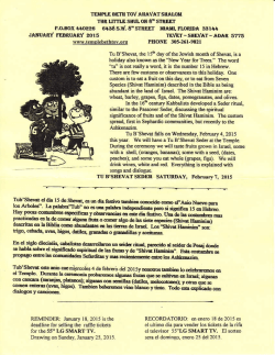
Power-Stud+ SD2
®
Wedge Expansion Anchor
ON
AL
I F I C AT I
AL
General Applications And Uses
ON
SEI
TE
RE
SEI
TE
RE
TE
N
IO
D C ONC
QU
C R AC
KE
D C ONC
IC REG
SM
ION ZO
NE
NS
ION ZO
QU
C R AC
KE
The Power-Stud+ SD2 anchor is a fully threaded, torque-controlled, wedge expansion anchor which is designed
for consistent performance in cracked and uncracked concrete. Suitable base materials include normal-weight
concrete, sand-lightweight concrete and concrete over steel deck. The anchor is manufactured with a zinc
IC REG
SM plated
carbon steel body and stainless steel expansion clip for premium performance.
N
IO
NS
NE
TE
Product Desciption
TI
I F•
I CSAtructural
connections, i.e., beam and column anchorage
• Utility and safety-related attachments
• Interior applications / low level corrosion environment
• Tension zone applications, i.e., cable trays and strut, pipe supports, fire sprinklers
• Seismic and wind loading
• Medium to heavy duty purposes
Features And Benefits
+ Consistent performance in high and low strength concrete
+ Nominal drill bit size is the same as the anchor diameter
+ Anchor can be installed through standard fixture holes
+ Length ID code and identifying marking stamped on head of each anchor
+ Anchor design allows for follow-up expansion after setting under tensile loading
thread verison
UNC Threaded Stud
Approvals And Listings
International Code Council, Evaluation Service (ICC-ES), ESR-2502 for concrete Code compliant with the
2012 IBC, 2012 IRC, 2009 IBC, 2009 IRC, 2006 IBC, 2006 IRC, 2003 IBC, and 2003 IRC
Zinc plated carbon steel body with
Tested in accordance with ACI 355.2 and ICC-ES AC193 for use in structural concrete under the design
stainless steel expansion clip, zinc plated
provisions of ACI 318 (Strength Design method using Appendix D)
carbon steel nut and washer
Evaluated and qualified by an accredited independent testing laboratory for recognition in
rod/Anchor size range (typ.)
cracked and uncracked concrete including seismic and wind loading (Category 1 anchors)
3/8” diameter through 3/4” diameter
FM Global (Factory Mutual) - File No. 3033795, 3/8” and 1/2” diameters
Pipe hanger components for automatic sprinkler systems
suitable base materials
Underwriters Laboratories (UL Listed) - File No. EX1289 - See listing.
Anchor Materials
Normal-weight Concrete
Guide Specifications
Sand-lightweight Concrete
Concrete over Steel Deck
Grouted Concrete Masonry (CMU)
This Product Available In
®
Powers Design Assist
Real Time Anchor Design Software
www.powersdesignassist.com
2
CSI Divisions: 03 16 00 - Concrete Anchoring and 05 05 19 - Post Installed Concrete Anchors Expansion
anchors shall be Power-Stud+ SD2 as supplied by Powers Fasteners, Inc., Brewster, NY. Anchors shall be
installed in accordance with published instructions and the Authority Having Jurisdiction.
Material Specifications
Anchor component
Specification
Anchor Body
Medium carbon steel
Hex nut
Carbon steel, ASTM A 563, Grade A
Washer
Carbon Steel, ASTM F 844; meets dimensional requirements of
ANSI B18.22.2. Type A Plain
Expansion wedge (clip)
Type 316 Stainless Steel
Plating (anchor body, nut and washer)
Zinc plating according to ASTM B 633, SC1 Type III (Fe/Zn 5).
Minimum plating requirements for Mild Service Condition.
Power-Stud+ SD2
®
INSTALLATION SPECIFICATIONS
Installation Table for Power-Stud+ SD21
Anchor Property/
Setting Information
Nominal Anchor Size
Notation
Units
Anchor diameter
do
Minimum diameter of hole
clearance in fixture
dh
in.
(mm)
in.
(mm)
Nominal drill bit diameter
dbit
in.
Minimum nominal
embedment depth
hnom
Minimum concrete
member thickness1
hmin
Minimum overall anchor length
ℓanch
Minimum edge distance1
cmin
Minimum spacing distance1
smin
Critical edge distance1
cac
Installation torque
Tinst
in.
(mm)
in.
(mm)
in.
(mm)
in.
(mm)
in.
(mm)
in.
(mm)
in.
(mm)
in.
(mm)
ft.-lb.
(N-m)
Torque wrench socket size
-
in.
Nut height
-
in.
Effective embedment
hef
Minimum hole depth
ho
1
3/8”
1/2”
5/8”
3/4”
0.375
(9.5)
7/16
(11.1)
3/8
ANSI
2-3/8
(60)
2
(51)
2-5/8
(67)
4
(102)
3
(76.2)
2-1/2
(63.5)
3-1/2
(88.9)
6-1/2
(165.1)
20
(27)
0.500
(12.7)
9/16
(14.3)
1/2
ANSI
0.625
(15.9)
11/16
(17.5)
5/8
ANSI
0.750
(19.1)
13/16
(20.6)
3/4
ANSI
2-1/2
(64)
2
(51)
2-3/4
(70)
4-1/2
(114)
3-3/4
(95)
3-1/4
(83)
4
(102)
6
(152)
5-3/4
(146)
3-3/4
(95)
5-3/4
(146)
4-7/8
(124)
4-1/4
(108)
5-1/4
(133)
6-1/2
(165)
4-1/2
(114)
3-3/4
(95)
5
(127)
7
(178)
5-1/2
(140)
5
(127)
6
(152)
12
(305)
8
(203)
5-3/4
(146)
5
(127)
6-1/4
(159)
10
(254)
7
(178)
4-1/2
(114)
6
(152)
12
(305)
40
(54)
6
(152)
4-1/4
(108)
4-1/4
(108)
15-3/4
10
(400)
(254)
60
(81)
9/16
3/4
15/16
1-1/8
21/64
7/16
35/64
41/64
4
(102)
6
(152)
4-1/2
(114)
3-7/8
(98)
3-1/4
(83)
4-1/4
(108)
5-3/4
(146)
4-3/4
(121)
4-1/4
(108)
4-1/4
(108)
8
(203)
2-3/4
(70)
6
(152)
4
(102)
4
(102)
8
(203)
2-3/4
(70)
6
(152)
10
(254)
110
(149)
1. For installations through the soffit of steel deck into concrete, see the installation detail. Anchors in the lower flute may be installed with a maximum 1-inch offset in either direction
from center of the flute. In addition, anchors shall have an axial spacing along the flute equal to the greater of 3hef or 1.5 times the flute width.
Anchor Detail
Head Marking
Length Identification
Mark
Legend
Letter Code = Length Identification Mark
‘+’ Symbol = Strength Design Compliant Anchor
(see ordering information)
Number Code = Carbon Steel Body and Stainless
Steel Expansion Clip (not on 1/4” diameter anchors)
C
D
E
F
G
H
I
J
K
L
M
N
O
P
From
2-1/2"
3"
3-1/2"
4"
4-1/2"
5"
5-1/2"
6"
6-1/2"
7"
Up to but
not including
3"
3-1/2"
4"
4-1/2"
5"
5-1/2"
6"
6-1/2"
7"
7-1/2"
7-1/2" 8"
8"
8-1/2”
9”
8-1/2"
9”
9-1/2”
Length identification mark indicates
overall length of anchor.
3
Power-Stud+ SD2
®
INSTALLATION INSTRUCTIONs
1.) Using the proper drill
bit size, drill a hole into the
base material to the required
depth. The tolerances of the
drill bit used should meet the
requirements of ANSI
Standard B212.15.
4
2
2.) Remove dust and debris from 3.) Position the supplied washer 4.) Tighten the anchor with a
the hole using a hand pump,
on the anchor and thread on
torque wrench by applying the
compressed air or a vacuum.
the supplied nut. If installing
required installation torque, Tinst.
through a fixture, drive the
anchor through the fixture into
the hole. Be sure the anchor is
driven to the minimum required
embedment depth, hnom
Power-Stud+ SD2
®
INSTALLATION INSTRUCTIONs
Installation Detail A: for Power-Stud+ SD2 Installed Through Soffit of Steel Deck into Concrete1
Installation Detail B: for Power-Stud+ SD2 Installed Through Soffit of Steel Deck into Concrete2,3
1. Anchors may be placed in the upper flute or lower flute of the steel deck profiles in accordance with installation Detail A provided the minimum hole clearance is satisfied. Anchors
in the lower flute of installation Detail A profiles may be installed with a maximum 1-inch offset in either direction from the center of the flute. The offset distance may be increased
proportionally for profiles with lower flute widths greater than those shown provided the minimum lower flute edge distance is also satisfied.
2. Anchors may be placed in the lower flute of the steel deck profiles in accordance with installation Detail B provided the minimum hole clearance is satisfied. Anchors in the lower flute
of installation Detail B profiles may be installed with a maximum 1/8-inch offset in either direction from the center of the flute. The offset distance may be increased proportionally for
profiles with lower flute widths greater than those shown provided the minimum lower flute edge distance is also satisfied.
3. Anchors may be placed in the upper flute of the steel deck profiles in accordance with installation Detail B provided the concrete thickness above the upper flute is minimum
3-1/4-inch a minimum hole clearance 3/4-inch is satisfied.
3
Power-Stud+ SD2
®
performance data information
Tension Design information (For Use with load combinations taken from ACI 318 Section 9.2)1,2
Design Characteristic
Anchor category
Notation
Units
1,2 or 3
-
3/8
1/2
1
Nominal Anchor Diameter
5/8
3/4
1
1
1
85.0
(586)
106.0
(731)
0.1007
(65.0)
10,445
(48.0)
85.0
(586)
106.0
(731)
0.1619
(104.5)
13,080
(58.2)
70.0
(483)
90.0
(620)
0.2359
(153.2)
21,230
(94.4)
STEEL STRENGTH IN TENSION
4
Minimum specified yield strength (neck)
fy
Minimum specified ultimate tensile strength (neck)
futa
Effective tensile stress area (neck)
Ase
Steel strength in tension
Nsa
ksi
(N/mm2)
ksi
(N/mm2)
in2
(mm2)
lb
(kN)
Reduction factor for steel strength3
Φ
-
96.0
(662)
120.0
(827)
0.0552
(35.6)
6,625
(29.4)
0.75
CONCRETE BREAKOUT STRENGTH IN TENSION
Effective embedment
hef
in.
(mm)
2.00
(51)
Effectiveness factor for uncracked concrete
kucr
-
24
Effectiveness factor for cracked concrete
kcr
-
ψ c,N
Modification factor for cracked and uncracked concrete5
-
Critical edge distance
cac
in.
(mm)
Reduction factor for concrete breakout strength3
Φ
-
2.00
(51)
3.25
(83)
3.25
(83)
24
4.25
(108)
24
3.75
(95)
5.00
(127)
24
17
17
17
17
1.0
See note 5
6-1/2
(165)
1.0
See note 5
8
10
(203)
(254)
1.0
See note 5
8
15-3/4
(203)
(400)
1.0
See note 5
12
6-1/2
(305)
(165)
0.65 (Condition B)
PULLOUT STRENGTH IN TENSION (NON-SEISMIC APPLICATIONS)
8
Characteristic pullout strength, uncracked concrete (2,500 psi)6
Np,uncr
Characteristic pullout strength, cracked concrete (2,500 psi)6
Np,cr
lb
(kN)
lb
(kN)
Φ
-
Reduction factor for pullout strength3
2,775
(12.3)
2,165
(9.3)
6,615
(29.4)
4,375
(19.5)
See note 7
See note 7
See note 7 See note 7 See note 7 See note 7
See note 7 See note 7 See note 7
7,795
(35.1)
0.65 (Condition B)
PULLOUT STRENGTH IN TENSION FOR SEISMIC APPLICATIONS
8
Characteristic pullout strength, seismic (2,500 psi)
6,9
Reduction factor for pullout strength3
Neq
(Np,seis)
lb
(kN)
Φ
-
2,165
(9.3)
See note 7
4,375
(19.5)
See note 7 See note 7 See note 7
7,795
(35.1)
0.65 (Condition B)
PULLOUT STRENGTH IN TENSION FOR SAND-LIGHT WEIGHT AND NORMAL-WEIGHT CONCRETE OVER STEEL DECK
Characteristic pullout strength, cracked concrete over steel
deck, according to Installation Detail A10
Characteristic pullout strength, uncracked concrete over steel
deck, according to Installation Detail A10
Characteristic pullout strength, uncracked concrete over steel
deck, according to Installation Detail B10
Characteristic pullout strength, cracked concrete over steel deck,
according to Installation Detail B10
Reduction factor for pullout strength3
Np,deck,uncr
lb
(kN)
lb
(kN)
lb
(kN)
lb
(kN)
Φ
-
Np,deck,uncr
Np,deck,cr
Np,deck,cr
1,855
(8.3)
1,445
(6.4)
1,600
(5.6)
1,250
(5.6)
2,065
(9.2)
1,465
(6.5)
2,025
(6.4)
1,435
(6.4)
3,930
(17.5)
2,600
(11.6)
Not
Applicable
Not
Applicable
4,665
(20.8)
3,305
(14.7)
Not
Applicable
Not
Applicable
7,365
(32.8)
5,215
(23.2)
Not
Applicable
Not
Applicable
4,900
(21.8)
3,470
(15.4)
Not Applicable
Not Applicable
0.65 (Condition B)
1. The data in this table is intended to be used with the design provisions of ACI 318 Appendix D; for anchors resisting seismic load combinations the additional requirements of ACI 318 D.3.3 shall apply.
2. Installation must comply with published instructions and details.
3. All values of Φ were determined from the load combinations of ACI 318 Section 9.2. If the load combinations of Appendix C are used, the appropriate value of Φ must be determined in accordance with ACI 318 D.4.5. For
reinforcement that meets ACI 318 Appendix D requirements for Condition A, see ACI 318 D.4.4 for the appropriate Φ factor.
4. The Power-Stud+ SD2 is considered a ductile steel element in tension as defined by ACI 318 D.1. Reported values for steel strength in tension are based on test results per ACI 355.2 and shall be used for design.
5. For all design cases use ψ c,N = 1.0. Select appropriate effectiveness factor for cracked concrete (kcr) or uncracked concrete (kuncr).
6. For all design cases use ψ c,P = 1.0. For concrete compressive strength greater than 2,500 psi, Npn = (pullout strength value from table)*(specified concrete compressive strength/2500)n. For concrete over steel deck the
value of 2500 must be replaced with the value of 3000. For all anchors n = 1/2 with the exception of the 3/8” anchor size for cracked concrete where n = 1/3.
7. Pullout strength does not control design of indicated anchors. Do not calculate pullout strength for indicated anchor size and embedment.
8. Anchors are permitted to be used in sand-lightweight concrete provided that Nb, Neq and Npn are multiplied by a factor of 0.60 (not required for steel deck).
9. Reported values for characteristic pullout strength in tension for seismic applications are based on test results per ACI 355.2, Section 9.5.
10. Values for Np, deck are for sand-lightweight concrete (f’c, min = 3,000 psi) and additional lightweight concrete reduction factors need not be applied. In addition, evaluation for the concrete breakout capacity in accordance
with ACI 318 D.5.2 is not required for anchors installed in the flute (soffit).
6
Power-Stud+ SD2
®
performance data information
Shear Design information (For Use with load combinations taken from ACI 318 Section 9.2)1-2
Design Characteristic
Anchor category
Notation
Units
1,2 or 3
-
Nominal Anchor Diameter
5/8
3/8
1/2
3/4
1
1
1
1
68.0
(469)
88.0
(607)
0.1419
(65.7)
4,815
(21.4)
68.0
(469)
88.0
(607)
0.2260
(104.9)
10,170
(45.7)
56.0
(386)
80.0
(551)
0.3345
(215.8)
12,610
(56.1)
STEEL STRENGTH IN SHEAR4
Minimum specified yield strength (threads)
fy
Minimum specified ultimate tensile strength (threads)
futa
Effective tensile stress area (threads)
Ase
Steel strength in shear
Vsa
ksi
(N/mm2)
ksi
(N/mm2)
in2
(mm2)
lb
(kN)
Reduction factor for steel strength3
Φ
-
76.8
(530)
100.0
(689)
0.0775
(50.0)
3,115
(13.9)
0.65
CONCRETE BREAKOUT STRENGTH IN SHEAR
6
Load bearing length of anchor
(hef or 8do, whichever is less)
ℓe
in.
(mm)
Reduction factor for concrete breakout strength3
Φ
-
2.00
(51)
2.00
(51)
3.25
(83)
3.25
(83)
4.25
(108)
3.75
(95)
5.00
(127)
0.70 (Condition B)
PRYOUT STRENGTH IN SHEAR6
Coefficient for pryout strength
(1.0) for hef < 2.5 in., 2.0 for hef ≥ 2.5 in.
kcp
-
1.0
1.0
2.0
2.0
2.0
2.0
2.0
Characteristic pullout strength, cracked concrete (2,500 psi)6
hef
in.
(mm)
2.00
(51)
2.00
(51)
3.25
(83)
3.25
(83)
4.25
(108)
3.75
(95)
5.00
(127)
Reduction factor for pullout strength3
Φ
-
0.70 (Condition B)
STEEL STRENGTH IN SHEAR FOR SEISMIC APPLICATIONS
6
Steel Strength in shear, seismic
7
Reduction factor for pullout strength3
Veq
(Vsa,seis)
lb
(kN)
2,460
(9.7)
Φ
-
0.60
4,815
(21.4)
6,770
(30.1)
8,060
(35.9)
0.65 (Condition B)
PULLOUT STRENGTH IN TENSION FOR SAND-LIGHT WEIGHT AND NORMAL-WEIGHT CONCRETE OVER STEEL DECK9
Steel strength in shear,
concrete over steel deck, according to installation Detail A8
Steel strength in shear, seismic
concrete over steel deck, according to installation Detail A8
Steel strength in shear,
concrete over steel deck, according to installation Detail B8
Steel strength in shear, seismic
concerete over steel deck, according to installation Detail B8
Reduction factor for steel strength in shear,
concrete over steel deck3
Vsa,deck,eq
lb
(kN)
lb
(kN)
lb
(kN)
lb
(kN)
Φ
-
Vsa,deck
Vsa,deck,eq
Vsa,deck
2,170
(9.7)
1,940
(8.6
2,170
(9.7)
1,940
(8.6)
3,815
(17.0)
3,815
(17.0)
2,880
(12.8)
2,880
(12.8)
5,040
(22.4)
5,040
(22.4)
Not
Applicable
Not
Applicable
4,015
(17.9)
2,675
(11.9)
Not
Applicable
Not
Applicable
6,670
(29.7)
4,445
(19.8)
Not
Applicable
Not
Applicable
4,325
(19.2)
2,820
(12.5)
Not Applicable
Not Applicable
0.65
1. The data in this table is intended to be used with the design provisions of ACI 318 Appendix D; for anchors resisting seismic load combinations the additional requirements of AC 318 D.3.3
shall apply.
2. Installation must comply with published instructions and details.
3. All values of Φ were determined from the load combinations of ACI 318 Section 9.2. If the load combinations of Appendix C are used, the appropriate value of Φ must be determined in
accordance with ACI 318 Section D.4.5. For reinforcement that meets ACI 318 Appendix D requirements for Condition A, see ACI 318 D.4.4 for the appropriate Φ factor.
4. The Power-Stud+ SD2 is considered a ductile steel element as defined by ACI 318 D.1 with the exception of the 3/8” anchor size in shear.
5. Reported values for steel strength in shear are based on test results per ACI 355.2, Section 9.4 and shall be used for design. These reported values may be lower than calculated results
using equation D-20 in ACI 318-05 D.6.1.2 and D-18 in ACI 318-02, D.6.1.2.
6. Anchors are permitted to used in structural sand-lightweight concrete provided that Vb and Vcp are multiplied by a factor of 0.60 (not required for steel deck).
7. Reported values for steel strength in shear for seismic applications are based on test results per ACI 355.2, Section 9.6.
8. Values for Vsa, deck are for sand-lightweight concrete (f’c, min = 3,000 psi) and additional lightweight concrete reduction factors need not be applied. In addition, evaluation for
the concrete breakout capacity in accordance with ACI 318 D.6.2 and the pryout capacity in accordance with ACI 318 D.6.3 are not required for anchors installed in the flute (soffit).
9. Shear loads for anchors installed through steel deck into concrete may be applied in any direction.
7
Power-Stud+ SD2
TM
Factored Design Strength ( fNn and fVn) Calculated in Accordance with ACI 318 Appendix D:
1. Tabular values are provided for illustration and are applicable for single anchors installed in normal-weight concrete
with minimum slab thickness, ha = hmin, and with the following conditions:
- ca1 is greater than or equal to the critical edge distance, cac (table values based on ca1 = cac).
- ca2 is greater than or equal to 1.5 ca1.
2. Calculations were performed according to ACI 318-08 Appendix D. The load level corresponding to the controlling
failure mode is listed (e.g. For tension: steel, concrete breakout and pullout; For shear: steel, concrete breakout and
pryout). Furthermore, the capacities for concrete breakout strength in tension and pryout strength in shear are calculated
using the effective embedment values, hef, for the selected anchors as noted in the design information tables.
Please also reference the installation specifications for more information.
3. Strength reduction factors (f) were based on ACI 318 Section 9.2 for load combinations. Condition B is assumed.
4. Tabular values are permitted for static loads only, seismic loading is not considered with these tables.
5. For designs that include combined tension and shear, the interaction of tension and shear loads must be calculated in accordance with ACI 318 Appendix D.
6. Interpolation is not permitted to be used with the tabular values. For intermediate base material compressive strengths please
see ACI 318 Appendix D. For other design conditions including seismic considerations please see ACI 318 Appendix D.
Ca1
ha
Ca2
Tension and Shear Design Strengths for Power-Stud+ SD2 in Cracked Concrete
Minimum Concrete Compressive Strength, f’c (psi)
Nominal
Anchor
Diameter
(in.)
Nominal
Embed.
hnom
(in.)
3/8
2,500
3,000
4,000
6,000
8,000
fNn
Tension
(lbs.)
fVn
Shear
(lbs.)
fNn
Tension
(lbs.)
fVn
Shear
(lbs.)
fNn
Tension
(lbs.)
fVn
Shear
(lbs.)
fNn
Tension
(lbs.)
fVn
Shear
(lbs.)
fNn
Tension
(lbs.)
fVn
Shear
(lbs.)
2-3/8
1,405
1,685
1,495
1,845
1,645
2,025
1,880
2,025
2,070
2,025
1/2
2-1/2
1,565
1,685
1,710
1,845
1,975
2,130
2,420
2,605
2,795
3,010
1/2
3-3/4
2,845
3,130
3,115
3,130
3,595
3,130
4,405
3,130
5,085
3,130
5/8
3-7/8
3,235
6,610
3,545
6,610
4,095
6,610
5,015
6,610
5,790
6,610
5/8
4-7/8
4,840
6,610
5,305
6,610
6,123
6,610
7,500
6,610
8,660
6,610
3/4
4-1/2
4,010
8,195
4,395
8,195
5,075
8,195
6,215
8,195
7,175
8,195
3/4
5-3/4
5,065
8,195
5,550
8,195
6,410
8,195
7,850
8,195
9,065
8,195
Tension and Shear Design Strengths for Power-Stud+ SD2 in Uncracked Concrete
Minimum Concrete Compressive Strength, f’c (psi)
Nominal
Anchor
Diameter
(in.)
Nominal
Embed.
hnom
(in.)
3/8
2,500
3,000
4,000
6,000
8,000
fNn
Tension
(lbs.)
fVn
Shear
(lbs.)
fNn
Tension
(lbs.)
fVn
Shear
(lbs.)
fNn
Tension
(lbs.)
fVn
Shear
(lbs.)
fNn
Tension
(lbs.)
fVn
Shear
(lbs.)
fNn
Tension
(lbs.)
fVn
Shear
(lbs.)
2-3/8
1,805
2,025
1,915
2,025
2,105
2,025
2,405
2,025
2,650
2,025
1/2
2-1/2
2,205
2,375
2,415
2,605
2,790
3,130
3,420
3,130
3,945
3,130
1/2
3-3/4
4,300
3,130
4,710
3,130
5,440
3,130
6,660
3,130
7,690
3,130
5/8
3-7/8
4,570
6,610
5,005
6,610
5,780
6,610
7,080
6,610
8,175
6,610
5/8
4-7/8
6,835
6,610
7,485
6,610
8,645
6,610
9,810
6,610
9,810
6,610
3/4
4-1/2
5,665
8,195
6,205
8,195
7,165
8,195
8,775
8,195
10,130
8,195
3/4
5-3/4
8,720
8,195
9,555
8,195
11,030
8,195
13,510
8,195
15,600
8,195
Steel Strength Controls
Concrete Breakout Strength Controls
Anchor Pullout/Pryout Strength Controls
Factored design strengths may be converted to allowable loads using an appropriate conversion factor, å, for the controlling load combination. See ICC-ES ESR-2502.
8
Power-Stud+ SD2
®
ULTIMATE AND ALLOWANCE LOADS
Converted Allowable Loads for Power-Stud+ SD2 in Cracked Concrete1,2
Minimum Concrete Compressive Strength, f’c (psi)
Nominal
Anchor
Size
(in.)
Nominal
Embed.
hnom
(in.)
Tallowable,ASD
Vallowable,ASD
Tallowable,ASD
Vallowable,ASD
Tallowable,ASD
Vallowable,ASD
Tallowable,ASD
Vallowable,ASD
Tallowable,ASD
Vallowable,ASD
3/8
2-3/8
1,005
1,205
1,070
1,320
1,175
1,445
1,345
1,445
1,480
1,445
1/2
2-1/2
1,120
1,205
1,220
1,320
1,410
1,520
1,730
1,860
1,995
2,150
1/2
3-3/4
2,030
2,235
2,225
2,235
2,570
2,235
3,145
2,235
3,630
2,235
5/8
3-7/8
2,310
4,720
2,530
4,720
2,925
4,720
3,580
4,720
4,135
4,720
5/8
4-7/8
3,455
4,720
3,790
4,720
4,375
4,720
5,355
4,720
6,185
4,720
3/4
4-1/2
2,865
5,855
3,140
5,855
3,625
5,855
4,440
5,855
5,125
5,855
3/4
5-3/4
3,620
5,855
3,965
5,855
4,580
5,855
5,605
5,855
6,475
5,855
2,500
Tension
(lbs.)
3,000
Shear
(lbs.)
Tension
(lbs.)
4,000
Shear
(lbs.)
Tension
(lbs.)
6,000
Shear
(lbs.)
Tension
(lbs.)
8,000
Shear
(lbs.)
Tension
(lbs.)
Shear
(lbs.)
Converted Allowable Loads for Power-Stud+ SD2 in Uncracked Concrete1,2
Minimum Concrete Compressive Strength, f’c (psi)
Nominal
Anchor
Size
(in.)
Nominal
Embed.
hnom
(in.)
Tallowable,ASD
Vallowable,ASD
Tallowable,ASD
Vallowable,ASD
Tallowable,ASD
Vallowable,ASD
Tallowable,ASD
Vallowable,ASD
Tallowable,ASD
Vallowable,ASD
3/8
2-3/8
1,290
1,445
1,370
1,445
1,505
1,445
1,720
1,445
1,895
1,445
1/2
2-1/2
1,575
1,695
1,725
1,860
1,995
2,235
2,445
2,235
2,820
2,235
1/2
3-3/4
3,070
2,235
3,365
2,235
3,885
2,235
4,755
2,235
5,495
2,235
5/8
3-7/8
3,265
4,720
3,575
4,720
4,130
4,720
5,055
4,720
5,840
4,720
5/8
4-7/8
4,880
4,720
5,345
4,720
6,175
4,720
7,005
4,720
7,005
4,720
3/4
4-1/2
4,045
5,855
4,430
5,855
5,120
5,855
6,270
5,855
7,235
5,855
3/4
5-3/4
6,230
5,855
6,825
5,855
7,880
5,855
9,650
5,855
11,145
5,855
2,500
Tension
(lbs.)
3,000
Shear
(lbs.)
Tension
(lbs.)
4,000
Shear
(lbs.)
Tension
(lbs.)
6,000
Shear
(lbs.)
Tension
(lbs.)
8,000
Shear
(lbs.)
Tension
(lbs.)
Shear
(lbs.)
1. Allowable load values are calculated using a conversion factor, å, from Factored Design Strengths and conditions shown on the previous page.
2. Tabulated allowable load values assume 50% dead load and 50% live load, with controlling load combination 1.2D + 1.6L. Calculated weighted average for the conversion factor,
å : 1.2(0.5) + 1.6(0.5) = 1.4.
Ultimate and Allowable Load Capacities for Power-Stud+ SD2 in Grouted Filled Concrete Masonry1,2,3
Minimum Masonry Compressive Strength,
f’m = 1,500 psi (10.4 MPa)
Nominal
Anchor
Size
in.
(mm)
Minimum
Embedment
Depth
(mm)
Installation
Location3
3/8
(9.5)
2-1/2
(50.8)
1/2
(12.7)
Ulimate Load
Tension
lbs.
(kN)
Allowable
Load
Tension
lbs.
(kN)
Ulimate Load
Shear
lbs.
(kN)
Allowable
Load
Shear
lbs.
(kN)
Wall Face
Min. 2-1/2” Edge
and End Distances
1,670
(7.4)
335
(1.5)
2,075
(9.2)
415
(1.8)
2-1/2
(50.8)
Wall Face
Min. 3” Edge and
End Distances
2,295
(10.2)
460
(2.0)
1,310
(5.8)
260
(1.2)
3-3/4
(95.3)
Top of Wall
Min. 1-3/4” Edge
and 4” Edge
Distances
3,320
(14.8)
665
(3.0)
1,140
(5.1)
230
(1.0)
1. Tabulated load values are for anchors installed in minimum 6-inch wide, minimum Grade N, Type II, lightweight, medium-weight or normal-weight concrete masonry units
conforming to ASTM C 90. Mortar must be minimum Type N. Masonry compressive strength must be at the specified minimum at the time of installation.
2. Allowable load capacities listed are calculated using and applied safety factor of 5.0. Consideration of safety factors of 10 or higher may be necessary depending upon
the application such as life safety.
3. Anchor installations into grouted masonry walls are limited to one per masonry cell.
9
Power-Stud+ SD2
TM
ordering information
Power-Stud+ SD2 (Carbon Steel Body with Stainless Steel Expansion Clip)
Cat No.
Anchor Size
Thread Length
Box Qty.
Carton Qty.
Wt./100 (lbs)
7413SD2
3/8” x 3”
1-3/4”
50
300
10
7414SD2
3/8” x 3-1/2”
2-1/4”
50
300
12
7415SD2
3/8” x 3-3/4”
2-1/2”
50
300
13
7416SD2
3/8” x 5”
3-3/4”
50
300
16
7422SD2
1/2” x 3-3/4”
2-1/8”
50
200
23
7423SD2
1/2” x 4-1/2”
2-7/8”
50
200
28
7424SD2
1/2” x 5-1/2”
3-7/8”
50
150
32
7426SD2
1/2” x 7”
5-3/8”
25
100
44
7427SD2
1/2” x 8-1/2”
6-7/8”
25
100
46
7435SD2
5/8” x 4-3/4”
2-7/8”
25
100
52
7433SD2
5/8” x 5”
3-1/8”
25
50
57
7434SD2
5/8” x 6”
4-1/8”
25
75
64
7436SD2
5/8” x 7”
5-1/8”
25
75
72
7438SD2
5/8” x 8-1/2”
6-5/8”
25
75
84
7442SD2
3/4” x 5-1/2”
3-1/4”
20
60
88
7444SD2
3/4” x 6-1/4”
4”
20
60
90
7446SD2
3/4” x 7”
4-3/4”
20
60
95
7448SD2
3/4” x 8-1/2”
6-1/4”
10
40
95
The published size includes the diameter and the overall length of the anchor.
All anchors are packaged with nuts and washers.
Installation Accessories
Cat. No.
10
Anchor Size
Box Qty.
08465
Adjustable torque wrench with 1/2" square drive (10 to 150 ft.-lbs.)
1
08280
Hand pump / dust blower
1
Power-Stud+ SD2
TM
11
POWERS FASTENERS BRANCH INFORMATION
POWERS BRANCH INFORMATION
USA Locations FOR US CusTomer service
CITY
ADdress
Alabama
Atlanta
Boston
Charlotte Chicago
Dallas
Denver
Detroit
Florida
Houston
Indianapolis
Los Angeles
Maryland
Milwaukee
Minneapolis
Missouri
New Orleans
New York
Philadelphia
Phoenix
Pittsburgh
Portland
Rochester
Salt Lake City San Francisco
Seattle Tennessee
5405 Buford Hwy Suite 410 Norcross, GA 30071-3984
5405 Buford Hwy Suite 410 Norcross, GA 30071-3984
2 Powers Lane, Brewster, NY 10509
349 L West Tremont Avenue, Charlotte, NC 28203
2472 Wisconsin Avenue, Downers Grove, IL 60515
1300 IH 35 North, Suite #118, Carrollton TX 75006
2475 West Second Street #35, Denver, CO 80223
21600 Wyoming Avenue, Oak Park, MI 48237
2412 Lynx Lane, Orlando, FL 32804
13833 North Promenade, Suite 100, Stafford, TX 77477
15290 Stony Creek Way, Noblesville, IN 46060
2761 Dow Avenue, Tustin, CA 92780
3137-B Pennsy Drive, Landover, MD 20785
12020 W. Feerick Street, Milwaukee, WI 53222
351 Wilson Street, NE Minneapolis, MN 55413
3225 Harvester Road, Kansas City, KS 66115
102 Sampson Street, Houston, TX 77003
2 Powers Lane, Brewster, NY 10509
2 Powers Lane, Brewster, NY 10509
3602 E. Southern Ave, Suite 5 Phoenix, AZ 85040
1360 Island Avenue, Mckees Rocks, PA 15136
14221 NE 190th St., Suite 125, Woodinville, WA 98072
36 Van Auker Blvd., Rochester, NY 14608
3120 W. California Ave, Suite E, Salt Lake City, UT 84104
28970 Hopkins Street, Suite B+C, Hayward, CA 94545
14221 NE 190th St., Suite 125, Woodinville, WA 98072
221 Blanton Avenue, Nashville, TN 37210
international Locations
PHONE
678-966-0000
678-966-0000
800-524-3244
704-375-5012
630-960-3156
972-446-5985
303-922-9202
248-543-8600
813-626-4500
281-491-0351
317-773-1668
714-731-2500
301-773-1722
414-466-2400
612-331-3770
816-472-5033
713-228-1524
800-524-3244
800-524-3244 602-431-8024
412-771-3010
714-731-2500
800-524-3244 / 585-529-4188
801-466-9428
510-293-1500
714-731-2500
615-248-2667
Fax
678-966-9242
678-966-9242
877-871-1965
704-376-5517
630-960-3912
972-446-3674
303-922-9228
248-543-8601
813-626-4545
281-491-0367
317-773-1690
714-731-2566
301-341-5119
414-466-3993
612-331-3549
816-472-5040
713-228-1528
877-871-1965
877-871-1965
602-431-8027
412-771-9858
714-731-2566
877-871-1965/ 585-529-5319
801-466-3083
510-293-1505
714-731-2566
615-248-2676
Country/region
ADdress
PHONE
Fax
Australia
Canada
China Europe
Manitoba
New Zealand
Quebec
Factory 3, 205 Abbotts Road, Dandenong, South Victoria 3175
Peter Pratis
+61 3 8787 5888
6275 Millcreek Drive, Mississauga, Ontario L5N 7K6
Joe Diilio
1-800-567-7188
8/F, Lujiazui Fund Tower, No. 101, Zhu Lin Road, PuDong District, Tina Ge
+86-21-6162-1858*2234
Shanghai, China 200122
Westrak 208, 1771 SV Wieringerwerf, Netherlands
Colin Earl
+31 888 769 377
1810 Dublin Avenue Man. Winnipeg, R3H 0H3 Distributor
204-633-0064
PO Box 302 076 North Harbour Auckland
Clay Sesto
+64 9415 2425
721 Meloche Avenue, Dorval, Quebec H9P 2S5
Allan Hill
514-631-4216
+61 3 8787 5899
1-800-265-9680
+86-21-5080-5101
Latin & Caribbean Distribution Inquiries
Country/Region
ADdress
Latin America
Latin & Caribbean Distribution
Contact
1-800-524-3244
Contact
Allan Herbert
PHONE
Fax
0050767477749
877-871-1965
Country/Region
ADdress
PHONE
Fax
Brazil
Colombia
Costa Rica
Dominican Republic
Ecuador
HARD, Rua Dr. Humberto Pinheiro Viera, 150 Lote B, 55-47-40097209
1 B Distrito Industrial, Joinville, Brazil
Electrogeno, S.A., Carrera 52 #71c-38, Bogota, Colombia
(57) 1 6600 9436
Tecnofijaciones de Costa Rica,, La Uruca, costado Este del Banco Nacional, [email protected] 00-506-2256-8115/8117
Condominio Horizontal JW, Bodega #21, San Jose, Costa Rica
Cel Internacional s.a., Alajuela, Costa Rica, Apartado 674-4050
[email protected]
00-506-2432 5868
Calle Estancia Nueva #17 E Esquina Cul-De-Sac 9, San Geronimo, Santo Domingo
Rodfor Team
809-224-5615
Acero Comercial Ecuatoriano S.A., Av. La Prensa N45-14 y Telégrafo 1 – Quito
[email protected]
(593-2) 2454 333 Av. Juan Tanca Marengo Km. 1.7 – Guayaquil
[email protected]
(593-4) 2683 060 Multimateriales s.a., 1 calle, #33-88, Zona 1, Colonia Toledo, Guatemala 01011 [email protected]
00-502-2429-6700
Multiaccesorios, Av.A tiempo, #502, Parque, Nuevo Leon
[email protected]
00-52-81-8042-4200
Fulminantes Industriales, Encino No.1103, Col Granjas, Chihuahua
[email protected]
00-52-614-419-0090
Sergio Paulo Ramirez, Colonia Jardines de Jerez, Gardenias #103, Leon, Guanajuato
[email protected]
00-52-477-711-0670
Centro-Industrial, Via Cincuentenario, No. 7910, Ciudad Panama, Panama
(507) 302-8022
Mecsa, Via Argentina #46-70, Edif. Rattan, Planta Baja Local 5, Panama
[email protected]
00-507-269-4333
Fixa Panama, Via Porras, Edif. 54, Local #7, San Francisco
[email protected]
00-507-260-9505
Powers Peruana SAC, Av. Santa Catalina, 571 La Victoria, Lima 13, Peru
Martin Vasquez
00 511 265 8500
(www.powersperuana.com)
Anclajes Powers s.a., Calle Sucre/Qta. Maudora, #1721 Entre Cec Acosta Y Distributor
San Ignacio Chacao, Caracas [email protected]
58 212 264 1313
Ft. Farfan, 3-5 Ibis Avenue, Ibis Acres, San Juan Derek Cumming
(868) 674-7896
55-47-40097217
Guatemala
Mexico
Panama
Peru
Venezuela
Trinidad - Tobago
Contact
+31 227 594 759
204-694-1261
+64 9415 2627
514-631-2583
00-506-2256-8149
00-506-2440-1839
809-472-8640
(593-2) 2454 455 (593-4) 2683 059
00-502-2429-6767
00-52-81-1231-0048
00-52-614-419-8523
00-52-477-212-2478
00-507-269-1866
00 511 330 0909
58 212 263 0219
Note: The information and data contained within this documentation was current as of June 2014. The information is for marketing purposes only and is subject to change and updates as needed. Powers Fasteners, Inc. reserves the right to change designs and
specifications without notice or liability for such changes. Please contact Powers Fasteners for the most current and up to date available information or refer to our website at www.powers.com
Powers Fasteners 701 E. Joppa Road, Towson, MD 21286 P: (800) 524-3244 F:(877) 871-1965
www.powers.com
Cat. No. 49074 6/14
©2014 Powers Fasteners, Inc.

© Copyright 2026