
of the Cerberus Fossae, Mars: Evacuated Dikes - USRA
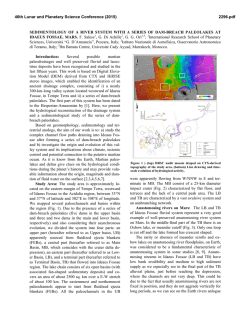
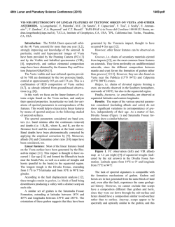
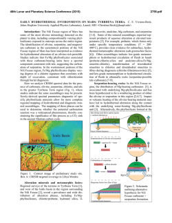
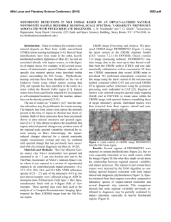
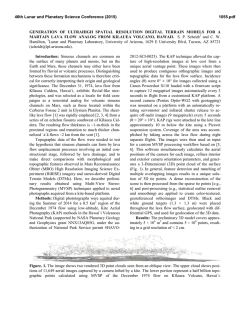
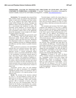
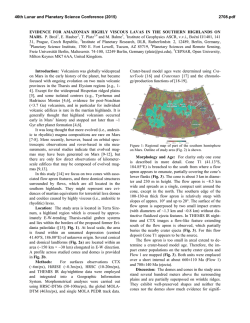
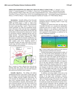
46th Lunar and Planetary Science Conference (2015)
2367.pdf
UNRAVELING THE FORMATION MECHANISM(S) OF THE CERBERUS FOSSAE, MARS:
EVACUATED DIKES, GRABEN, OR BOTH? Amanda L. Nahm1, Simon A. Kattenhorn2, and Matthew W.
Pendleton1, 1Department of Geological Sciences, University of Idaho, Moscow, ID 83844, [email protected];
[email protected], 2ConocoPhillips Company, 600 N. Dairy Ashford, Houston, TX 77079, [email protected].
Introduction: The Cerberus Fossae (CF) region
on Mars (6–12ºN, 154–174ºE) is located SE of Elysium Mons (Fig. 1) and is dominated by four sets of
SE-trending fractures which extend ~1200 km (Fig.
1). The fracture sets are spaced ~40–45 km apart and
are highly segmented. Relative to other geological
features in the area, the CF fractures are young, as
they cut most other features (craters, knobs of higher
topography, etc.) along their lengths. Crater counting
gives an age of the lavas that are cut by CF of ~100–
200 Ma [e.g., 1] thus giving a maximum age for the
observable fossae in the CF.
Hypothesized formation mechanisms: Previous
work has proposed that these fossae are the surface
expression of magmatic dikes that extend radially
from Elysium Mons [e.g., 2], especially as they appear to act as the source region for at least two Late
Amazonian megaflood channels (Athabasca and
Grjotà Valles). These floods have been interpreted as
either the result of magma-induced melting of the
cryosphere [1, 3, 4] or outflow of water from a
breached aquifer [5, 6] above an intruding dike beneath the fossae. Extensive lava flows emanate from
the Cerberus Fossae (CF) fissures [6–8], providing
support for this hypothesis.
Figure 1. Regional setting of the Cerberus Fossae. Colored Mars
Orbiter Laser Altimeter (MOLA) topography (128 ppd) overlain
on hillshade. CF fissures mapped in white. Place names labeled for
reference.
However, other past work suggests that the surface manifestation of the CF fissures is the result of
normal faulting, creating graben [4, 9, 10], and that
faulting and fossae collapse postdate flooding and
volcanism [e.g., 1, 5, 9]. Some studies [e.g., 4, 6, 11]
have also concluded that the graben may have formed
as a result of intrusion of underlying dikes.
Thus, while significant aspects of the volcanic and
fluvial history are well documented, the primary
mechanism(s) for the formation of the fossae are not
well understood. As one of the youngest tectonically
modified regions on Mars, CF is fundamentally important to understanding the interaction between volcano-tectonic processes and the near-surface cryosphere on Mars. Therefore, the primary goal of this
work is to determine whether the fossae are graben,
evacuated magmatic fissures (dikes), or ice meltrelated depressions through analysis of cross-strike
topography.
Figure 2. Comparison of the characteristic topography (vertical
displacement) for dike-induced topography (a) and tectonic graben
(b) in cross-section. (a) Model parameters for the hypothetical dike
shown here: 10-km high, 40-km long, rectangular vertical dike
with upper tip at 5 km depth and dike inflation of 1 m. (b) Model
parameters for a hypothetical graben shown here: 40-km-long,
graben-bounding normal faults spaced 4 km apart, dipping at 60º,
lower fault-tip depth of 3.8 km (so they do not intersect), and cumulative slip of 100 m. In addition to the different morphologies,
note the drastically different vertical scales [(a) dike in centimeters
versus (b) fault in meters]. Results calculated at the surface from
Coulomb program.
Comparison of dike and graben topography:
Graben produced by purely tectonic stresses (i.e.,
without subsurface dike intrusion) can be distinguished from dike-induced deformation by the detection of their subtle yet diagnostic topographic signature [e.g., 12–15]. For example, the surface topography produced by slip along two inwardly dipping
normal faults (i.e., graben) is elevated and concaveup in the footwall [12, 16, 17] and decays more rapidly with distance from the fault (Fig. 2b) than the
topographic swells characteristic of dike inflation in
the subsurface (Fig. 2a) [e.g., 12]. During dike inflation, the rock on either side of a vertical dike is displaced symmetrically outward and upward, forming
characteristic topographic swells [12] (Fig. 2a). Normal faults may then nucleate at the crests of the topographic swells and propagate downward, forming a
structural graben above the dike [e.g., 12–14, 18],
and the width of the graben scales with the depth to
the top of the dike [e.g., 12–15, 17, 19].
46th Lunar and Planetary Science Conference (2015)
Data: In order to use topography to distinguish
between these end-member formation mechanisms,
we utilize existing High Resolution Stereoscopic
Camera (HRSC) Digital Elevation Models (DEMs)
[20, 21] archived at http://hrscview.fu-berlin.de
available for the CF region.
Clustered topographic profiles were derived from
the HRSC DEMs perpendicular to each fossa trace.
The clustered profiles (spaced an average of 50 m
apart) were averaged. Representative averaged topographic profiles (numbered 1 through 6) and corresponding locations are shown in Fig. 3.
Figure 3. Representative topographic profiles for Cerberus Fossae.
Upper panel: Map showing the locations of the topographic profiles (yellow lines, numbered) and the Cerberus Fossae (outlined in
white). Background image: MOLA 128 pixel per degree hillshade.
The heavy black line in all profiles is the average of the clustered
profiles and the thin dotted lines are ±1 standard deviation. Y-axis:
elevation (m); X-axis: distance along profile (km)
Results and discussion: Despite the large coverage of CF by the HRSC DEMs (approximately 4050%), a total of 6 averaged profiles with potential
topographic signatures were obtained, likely as a result of the pre-existing topography and subsequent
modification of the fossae (see below). Based on
shape and comparison with Fig. 2, potential dike signatures are seen in 1, 2, 3, and 5, while potential graben signatures may be present in profiles 1, 4, and 6
(Fig. 3).
2367.pdf
This result was unanticipated given that the fossae
are well preserved, extensive, and young, making the
preservation of signatures more likely. As shown
above, the topography encompassing the central CF
is somewhat rugged and, in most cases, this likely
complicates the identification of characteristic dike or
graben topographic signatures. The en echelon, and
often overlapping, geometry of the fossae may have
contributed to the loss of or difficulty recognizing the
diagnostic signatures. Many profiles and images
show indications of probable late-stage (or at least
post-fossae formation) modification by surface processes. Topographic profiles show asymmetry immediately adjacent to the fossa, which may be influenced by knobs of older terrain near the fossa, modification of the near-fossa area from effusion of lava
or water, or collapse of the fossa walls.
The scalloped, non-linear rims of the fossae also
indicate that mass wasting and collapse modified the
plan view shape of the fossae. Features that resemble
the “collapsed fault scarps” of [22] are abundant in
CF and have been interpreted elsewhere on Mars to
result from widening of U-shaped troughs through
landslides and retreat of unstable normal fault scarps
[22]. This comparison, plus other observations, supports the idea that the Cerberus Fossae are underlain
by dikes or were at some time in the recent past. For
example, the effusion of large volumes of lava from
the fossae necessitates that these underlying dikes
reached the surface in many places. We therefore
envision a scenario in which most dikes reached the
surface, causing elongate depressions along them as
they melted the ground ice prior to eruption [e.g., 23],
erupting lava from multiple locations, and providing
a source for the water for the Late Amazonian floods.
Later, the dikes evacuated to form deep, narrow fissures (such as the fissure created during the 10th century Eldgjá eruption in southern central Iceland) with
rounded ends.
References: [1] Berman, D. C. and W. K. Hartmann (2002), Icarus, 159, 1–
17. [2] Kattenhorn, S. A. and J. A. Meyer (2010), 41st LPSC, Abstract
#1271. [3] Burr et al. (2002), GRL, 29, 1–3. [4] Head et al. (2003), GRL, 30,
1577. [5] Burr et al. (2002), Icarus, 159, 53–73. [6] Plescia, J. B. (2003),
Icarus, 164, 79-95. [7] Keszthelyi et al. (2000), JGR-Planets, 105, 1502715049. [8] Jaeger et al. (2007), Science, 317, 1709–1711. [9] Vetterlein, J.
and G. P. Roberts (2009), JGR-Planets, 114, E07003. [10] Vetterlein and
Roberts (2010), JSG, 32, 394–406. [11] Ernst et al. (2001), Ann. Rev. Earth
Planet. Sci., 29, 489–534. [12] Rubin, A. M. and D. D. Pollard (1988),
Geology, 16, 413–417. [13] Rubin, A. M. (1992), JGR, 97, 1839–1858. [14]
Mastin, L. G. and D. D. Pollard (1988), JGR, 93, 13221–13235. [15] Schultz
et al. (2004), Geology, 32, 889–892. [16] Weissel, J. K. and G. D. Karner
(1989), JGR, 94, 13919–13950. [17] Schultz, R. A. and J. Lin (2001), JGR,
106, 16549–16566. [18] Schultz, R. A. (1996), JSG, 18, 1139–1149. [19]
Okubo, C. H. and S. J. Martel (1998), J. Volcanol. Geotherm. Res., 86, 1–
18. [20] Gwinner et al. (2007), Proceedings of the ISPRS Working Group
IV/7 Workshop, Houston, 2007. [21] Gwinner et al. (2008), LPSC XXXIX,
Abstract #2373, 2008. [22] Mège et al. (2003), JGR, 108, 5044. [23] Pendleton, M. W. and S. A. Kattenhorn (2010), 44th LPSC, abstract #2525.
© Copyright 2026