
PDF (2.69 MB)
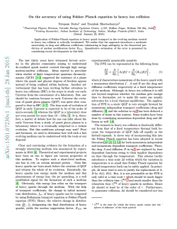
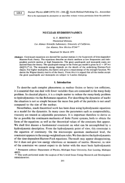
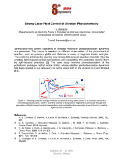
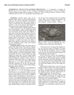
Home Search Collections Journals About Contact us My IOPscience Quantum interference of fast atoms scattered off crystal surfaces This content has been downloaded from IOPscience. Please scroll down to see the full text. 2015 J. Phys.: Conf. Ser. 583 012027 (http://iopscience.iop.org/1742-6596/583/1/012027) View the table of contents for this issue, or go to the journal homepage for more Download details: IP Address: 136.243.24.42 This content was downloaded on 06/02/2015 at 14:58 Please note that terms and conditions apply. 17th International Conference on the Physics of Highly Charged Ions Journal of Physics: Conference Series 583 (2015) 012027 IOP Publishing doi:10.1088/1742-6596/583/1/012027 Quantum interference of fast atoms scattered off crystal surfaces M S Gravielle Abstract. The striking observation of interference structures produced by grazing impact of fast atoms on crystal surfaces reported a few years ago [1,2] has given rise to the development of a powerful surface analysis technique. This article gives a brief account of the main features of the process, using the Surface Eikonal (SE) approximation as a theoretical tool to analyze the different mechanisms responsible for the quantum interference. The SE approach is a semiclassical method based on the use of the eikonal wave function, which takes into account the coherent superposition of transition amplitudes for different axially channeled trajectories. It has proved to provide a quite good description of experimental diffraction patterns for different collision systems. Instituto de Astronom´ıa y F´ısica del Espacio (IAFE, CONICET-UBA). Casilla de correo 67, sucursal 28 (C1428EGA) Buenos Aires, Argentina. E-mail: [email protected] 1. Introduction In the field of particle-surface dynamic interactions, one of the most interesting findings of recent years corresponds to the observation of quantum interference effects produced by fast atoms after grazingly colliding with crystal surfaces [1, 2]. The diffraction of particles from crystal surfaces is a well understood phenomenon from the beginning of quantum mechanics, having been key to the confirmation of one of the most fundamental concepts of quantum mechanics - the wave-particle duality. Hitherto the presence of interference effects in atom-surface scattering was believed to be confined to de Broglie wavelengths comparable or larger than the interatomic distances in the crystal, beyond which the collision process was supposed to be governed by Newton´s laws. However, a few years ago two different groups reported simultaneously [1, 2] experimental evidences of diffraction effects from insulator surfaces produced by grazing scattering of swift atoms, with energies in the range of keVs, whose de Broglie wavelengths are several orders of magnitude smaller than the shortest interatomic distance in the crystal. This unexpected phenomenon [3, 4], now known as grazing-incidence fast atom diffraction (GIFAD or FAD), is the focus of the present contribution. Since the first measurements of FAD [1, 2] the process has attracted remarkable attention, being the aim of extensive experimental and theoretical research [5, 6, 7, 8, 9, 10, 11, 12, 13, 14, 15, 16, 17]. Such an interest is motivated not only by the fast velocity of incident projectiles that made the observation of interference effects unforeseen, but also by the exceptional sensitivity of the diffraction patterns to the projectile-surface interaction [7, 8, 10, 18, 19, 20], which is paving the way for the development of a powerful surface analysis technique. The essential feature of FAD is the geometry of grazing collision, which makes somehow possible to decouple Content from this work may be used under the terms of the Creative Commons Attribution 3.0 licence. Any further distribution of this work must maintain attribution to the author(s) and the title of the work, journal citation and DOI. Published under licence by IOP Publishing Ltd 1 17th International Conference on the Physics of Highly Charged Ions Journal of Physics: Conference Series 583 (2015) 012027 IOP Publishing doi:10.1088/1742-6596/583/1/012027 the movement of the projectile along the channeling direction, too fast to allow for diffraction, from its much slower motion within the plane perpendicular to it. Hence, diffraction patterns are originated by this transverse motion. From the theoretical point of view, different methods have been employed to simulate experimental FAD patterns. They range from fully quantum treatments in terms of a wave packet propagation [2, 7, 21] to semiclassical approximations [5, 8] based on the use of classical projectile trajectories. Among these last theories we can mention the Surface Eikonal (SE) approximation [8, 22], which is a distorted-wave method that makes use of the eikonal wave function to represent the elastic collision with the surface, while the motion of the swift projectile is classically described by considering axially channeled trajectories for different initial positions. The SE approach includes a clear description of the main mechanisms of the FAD process, being simpler to evaluate than a full quantum calculation [7, 21]. It has been successfully applied to investigate FAD patterns for different collision systems [18, 22, 23, 24]. This work presents a general overview of the FAD phenomenon based on results derived within the SE approach. Concerning experimental research on FAD, a complete review, including basic features and recent experimental developments, has been recently published in Ref. [25]. Parts of this article have been separately published in Refs. [22, 23, 24]. Atomic units (e2 = = me = 1) are used unless otherwise stated. 2. Surface Eikonal approach Within the SE approximation the transition matrix per unit surface area A reads [8, 22] (SE) Tif = 1 A dRos aif (Ros ), (1) A where +∞ aif (Ros ) = dt vz (Rt ) (2π)3 exp[−iQ.Rt − iη(Rt ) − iφM ] VSP (Rt ) (2) −∞ represents the transition amplitude associated with the trajectory Rt , with Rt ≡ Rt (Ros ) the projectile position at a given time t obtained by considering a classical path with initial → − momentum Ki and starting position on the surface plane R os . In Eq. (2), vz (Rt ) denotes the component of the projectile velocity perpendicular to the surface plane and Q = Kf − Ki is the projectile momentum transfer, with Kf the final projectile momentum satisfying the energy conservation, i.e. Kf = Ki . The phase η is the eikonal phase, which is defined along the projectile path as t η(Rt ) = dt VSP (Rt ), (3) −∞ where VSP is the projectile-surface interaction, and φM = νπ/2 is the Maslov correction phase, with ν the Maslov index as defined in Ref. [26]. The SE differential probability, per unit of surface area, of elastic scattering with final momentum Kf in the direction of the solid angle Ωf ≡ (θf , ϕf ) is obtained from Eq. (1) (SE) 2 as dP/dΩf = (2π)4 m2P Tif , where θf and ϕf are the final polar and azimuthal angles, respectively, ϕf is measured with respect to the incidence direction on the surface plane, and mP is the projectile mass. A schematic picture of the FAD process and the angular coordinates is displayed in Fig. 1. With regard to the applicability of the method, the SE approach is valid for small de Broglie wavelengths, smaller than the characteristic distance of variation of the surface potential, which makes it especially suitable for the problem under study. 2 17th International Conference on the Physics of Highly Charged Ions Journal of Physics: Conference Series 583 (2015) 012027 IOP Publishing doi:10.1088/1742-6596/583/1/012027 Figure 1. (Color online) Sketch of the angular coordinates for the FAD process. 3. Energy dependence of FAD patterns When swift atoms grazingly impact on a well ordered surface along a low indexed direction, the projectile distribution shows the typical banana shape characteristic of axial surface channeling [27]. But in the FAD regime, such a distribution presents additionally clear interference structures [28], like the ones observed in Fig. 2 (a) for He atoms scattered off a LiF(001) surface [22]. In the cases of Fig. 2 (a), even though the de Broglie wavelengths of incident atoms are almost three orders of magnitude smaller than the shortest interatomic distance in the crystal, the experimental spectra show well-defined interference patterns, with maxima and minima located symmetrically with respect to the direction of incidence, which corresponds to the azimuthal angle ϕf = 0. Similar interference structures are also obtained with the SE approximation, which predicts projectile distributions with pronounced maxima whose positions, displayed with black dots in the figure, are in good agreement with the experimental ones. Notice that as a result of the energy conservation, final dispersion angles of classically scattered projectiles satisfy the relation θf2 + ϕ2f θi2 , with θi the incidence angle, which is approximately verified by the experimental distribution as well. 4 (b) He [110] LiF(001); Ei= const=1.04 eV Deflection angle (deg) 40 30 20 10 0 0 5 10 15 Ei (keV) Figure 2. (Color online)FAD for He atoms scattered from LiF(001) [22]. (a) Experimental two-dimensional intensity distributions for two incidence energies, Ei =2.2 keV and 7.5 keV, but with the same perpendicular energy. Black dots, positions of SE maxima. (b) Deflection angles Θ corresponding to maxima of angular distributions, as a function of Ei , for Ei⊥ =1.04 eV. Full circles, experimental data; curves, SE results. In Fig. 2 (a) the incidence angles for the two impact energies - Ei = 2.2 keV and 7.5 keV were set to obtain the same perpendicular energy - Ei⊥ =1.04 eV - where Ei⊥ = Ei sin2 θi is the energy associated with the initial motion perpendicular to the axial channel. This particular setting reveals that the number and Θ-positions of diffraction maxima, with Θ = arctan(ϕf /θf ) the deflection angle, are completely governed by the normal energy, being independent of Ei 3 17th International Conference on the Physics of Highly Charged Ions Journal of Physics: Conference Series 583 (2015) 012027 IOP Publishing doi:10.1088/1742-6596/583/1/012027 at the same Ei⊥ [22]. This behavior is more evident from Fig. 2 (b) where deflection angles corresponding to the experimental and SE maxima are plotted as a function of the total energy Ei while keeping Ei⊥ constant. 3 rainbow rainbow Differential probability (arb. units) He [110] LiF(001); Ei= 1.64 eV SE approach Experiment -40 -20 0 20 40 deflection angle (deg) Figure 3. (Color online) Projectile distribution, as a function of the deflection angle Θ, for 3.5 keV He atoms scattered from LiF(001) along the [110] direction [22]. Solid blue line, SE results (for a reduced unit cell); shadow gray line, experimental data. Experimental and theoretical projectile distributions, as a function of Θ, are plotted in Fig. 3 for He atoms impinging on LiF(001) with Ei⊥ =1.64 eV. The positions and relative intensities of the experimental peaks are fairly well described by the SE model. However, the concordance deteriorates at the largest deflection angles, which coincide with the classical rainbow ones, where the SE probability presents cusped peaks. The sharp increase of the SE probability at rainbow angles is a characteristic of several semi-classical approximations, widely studied in atom-surface scattering [29], which originates from the accumulation of classical trajectories (caustics) at this point. In quantum mechanics, instead, the sharp rainbow peaks are replaced by smooth maxima that display an exponentially decaying behavior beyond classical rainbow angles, just on the dark side, i.e. in the region of classically forbidden transitions [30]. A semi-quantum approach to solve the rainbow problem of the SE approach has been recently introduced in Ref. [31]. 4. Mechanisms of FAD: unit-cell and Bragg diffractions As it happens for most of diffraction phenomena from periodic structures, FAD patterns have two different origins: unit-cell and Bragg diffractions [5]. Both mechanisms are included in the SE description and can be separately analyzed as follows. Within the SE approximation, by considering the area A involved in Eq. (1) as composed by n identical reduced unit cells centered on different sites Xsj of the crystal surface, the transition matrix can be factorized as (SE) (SE) Tif,n = Tif,1 Sn (Qs ), (4) (SE) where Tif,1 is derived from Eq. (1) by evaluating the Ros -integral over only one reduced unit cell, while Sn (Qs ) = n j=1 exp −iQs .Xsj /n is an oscillatory function that takes into account the crystallographic structure of the surface, with Qs the component of Q parallel to the surface plane. 4 17th International Conference on the Physics of Highly Charged Ions Journal of Physics: Conference Series 583 (2015) 012027 IOP Publishing doi:10.1088/1742-6596/583/1/012027 Figure 4. (Color online) Schematic depiction of the different mechanisms involved in the FAD process: (a) unit-cell diffraction, and (b) Bragg diffraction. (SE) Each factor of Eq. (4) describes a different mechanism of FAD. The first factor, Tif,1 , is a form factor associated with unit-cell diffraction, being produced by the interference of trajectories whose initial positions Ros differ by a distance smaller than D, where D is the width of the reduced unit cell (Fig. 4 (a)). This unit-cell factor carries information on the shape of the interaction potential across the incidence direction and it is related to supernumerary rainbows [32]. The second factor, Sn (Qs ), is a crystallographic factor associated with Bragg diffraction, which originates from the interference of identical trajectories whose initial positions Ros are separated by a distance d equal to the spacial periodicity of the channel (Fig. 4 (b)). Under typical incidence conditions for FAD, it is possible to approximate Sn (Qs ) ≈ Sntr (Qtr ), where ntr is the number of reduced unit cells in the direction transversal to the incidence channel and Qtr = Kf cos θf sin ϕf Ki⊥ sin Θ is the component of Qs along such a direction, with Ki⊥ = Ki sin θi the perpendicular initial momentum. For periodic surfaces the function Sntr (Qtr ) gives rise to equal intensity Bragg peaks placed at Qtr d = m2π, (5) with m an integer that represents the Bragg order. The width of these Bragg peaks is determined by the number of reduced unit cells reached by the incident wave packet, narrowing as ntr increases. As illustrative example, in Fig. 5 we display the SE differential probability obtained from Eq. (1) by considering an area A formed by three reduced unit cells, which presents Bragg maxima at angular positions derived from Eq. (5). While the positions of Bragg peaks provide information on the spacing between surface atoms only, their intensities are modulated by the (SE) unit-cell form factor Tif,1 , which acts as an oscillatory envelope function that can reduce or even suppress the contribution of a given Bragg order, giving detailed information about the surface potential. Also from Eq. (5) it is straightforwardly deduced that when Ki⊥ increases, the angular separation between consecutive Bragg peaks decreases, and consequently, the experimental observation of Bragg diffraction becomes limited by the spatial resolution of the detector. This is the main reason why only interference structures due to unit-cell diffraction are observed in the experimental projectile distributions of Figs. 2 and 3, which correspond to perpendicular energies Ei⊥ 1 eV. 5 17th International Conference on the Physics of Highly Charged Ions Journal of Physics: Conference Series 583 (2015) 012027 1 -40 nd 2 supernum. supernum. Bragg He [110] LiF(001); Ei = 0.5 eV st rainbow Differential probability (arb. units) 3 IOP Publishing doi:10.1088/1742-6596/583/1/012027 -20 0 20 40 deflection angle (deg) Figure 5. (Color online) SE projectile distribution for He atoms scattered from LiF(001) [22]. Dashed red line, SE probability for unit-cell diffraction; solid blue line, similar by using an extended integration area, as explained in the text. Dotted vertical lines, Bragg peak positions. 5. Sensitivity with the surface interaction For most of the studied systems, not only the Θ positions but also the relative intensities of diffraction maxima are independent of Ei at the same perpendicular energy [22, 28]. This fact supports the assumption that in the typical FAD regime, even though the complete corrugation of VSP on the surface plane is taken into account within the SE approximation, the Qtr distribution is practically unaffected by the modulation of the potential along the channel, turning the threedimensional surface potential into an effective two-dimensional (2D) one [21, 33]. Therefore, an overall understanding of the FAD scenario for a given collision system can be obtained by displaying the so-called diffraction chart, which shows the intensity of the projectile distribution as a function of both, Ei⊥ and Qtr . In Fig. 6 we compare experimental and SE diffraction charts for He atoms impinging on a silver surface [24], which present reach interference structures, specially as the perpendicular energy increases. Taking into account that different values of Ei⊥ allow one to probe potential contours across the incidence direction for different distances to the surface, the general good agreement between the experimental and simulated diffraction charts of Fig. 6 is a signature of the quality of the potential model used in the calculations [24]. One of the most attractive characteristic of FAD is its extraordinary sensitivity to the morphological and electronic characteristics of the crystal surface. FAD patterns are strongly dependent on the corrugation of the projectile-surface potential across the incidence direction and subtle changes in the surface interaction introduce substantial modifications of the interference structures [7, 18, 25]. In Fig. 7, experimental momentum spectra for 0.5 keV He atoms impinging on a silver surface are compared with SE distributions considering three different perpendicular energies. The figure clearly shows that the intensity of the central peak, corresponding to the Bragg maximum of order m = 0, is extremely sensitive to the corrugation amplitude of the surface potential and a small variation in the Ei⊥ value strongly modifies the relative intensity of the zeroth order Bragg peak, which switches from being an absolute maximum for Ei⊥ = 0.20 eV to an almost absolute minimum for Ei⊥ = 0.28 eV [24]. 6. Conclusions In this paper we have used the SE approximation to present a brief overview of the FAD phenomenon, focusing on the main aspects of the quantum interference process. The SE 6 17th International Conference on the Physics of Highly Charged Ions Journal of Physics: Conference Series 583 (2015) 012027 IOP Publishing doi:10.1088/1742-6596/583/1/012027 Figure 6. (Color online) Diffraction charts displaying (a) experimental intensities and (b) SE probabilities, as a function of the normal energy Ei⊥ and the transverse momentum Qtr , for 0.5 keV He atoms scattered off Ag(110) [24]. 3 He [0 0 1] Ag(110) Ei= 0.24 eV -4 -2 0 2 -4 m= 1 Ei= 0.28 eV m= 0 m=-1 Differential probability (arb. units) Ei= 0.20 eV -2 0 º -1 2 -4 -2 0 2 4 Qtr (A ) Figure 7. (Color online) Momentum distributions, as a function of Qtr , for 0.5 keV He atoms scattered off Ag(110) [24]. The normal energy Ei⊥ is: (a) 0.20 eV, (b) 0.24 eV, and (c) 0.28 eV. Circles, experimental data; solid and dashed blue lines, SE probabilities convoluted to include inherent uncertainties and without convolution, respectively. The vertical dashed lines indicate Bragg peak positions. approximation is a semi-classical method that takes into account the quantum interference in terms of the coherent superposition of transition amplitudes for different projectile paths with the same deflection angle. This method has proved to give a fairly good representation of experimental diffraction patterns for different collision systems [8, 18, 22, 23, 24], providing a 7 17th International Conference on the Physics of Highly Charged Ions Journal of Physics: Conference Series 583 (2015) 012027 IOP Publishing doi:10.1088/1742-6596/583/1/012027 simple way of analyzing the different mechanism of FAD. Even though we have here considered only two illustrative surfaces - LiF(001) and Ag(110), which correspond to an insulator and a metal, respectively - the FAD technique has been successfully applied to investigate a wide range of materials, including semi-conductors [13, 36] and thin films [15] and superstructures adsorbed on metal surfaces [10, 17]. In relation to projectiles, FAD patterns were observed for He and Ne impact [5, 23], both inert atoms, as well as for incidence of atomic and molecular hydrogen [1, 2]. This last case, corresponding to fast molecular diffraction, represents a challenge for the theoretical methods and will be the focus of our future research. Acknowledgments Financial support from CONICET, UBA, and ANPCyT of Argentina is acknowledged. [1] Sch¨ uller A, Wethekam S and Winter H 2007 Phys. Rev. Lett. 98 016103 [2] Rousseau P, Khemliche H, Borisov A G and Roncin P 2007 Phys. Rev. Lett. 98 016104 [3] Interference structures of FAD had been predicted, before its experimental observation [1, 2], in a widely unknown article by Andreev [4]. [4] Andreev E A 2002 Russ. J. Phys. Chem. 76 S164 [5] Sch¨ uller A and Winter H 2008 Phys. Rev. Lett. 100 097602 [6] Manson J R, Khemliche H and Roncin P 2008 Phys. Rev. B 78 155408 [7] Aigner F, Simonovi´c N, Solleder B, Wirtz L and Burgd¨ orfer J 2008 Phys. Rev. Lett. 101 253201 [8] Gravielle M S and Miraglia J E 2008 Phys. Rev. A. 78 022901 [9] Bundaleski N, Khemliche H, Soulisse P and Roncin P 2008 Phys. Rev. Lett. 101 177601 [10] Sch¨ uller A, Busch M, Seifert J, Wethekam S, Winter H and G¨ artner K 2009 Phys. Rev. B 79 235425 [11] Ruiz A, Palao J P and Heller E J 2009 Phys. Rev. A 79 052901 [12] D´ıaz C, Rivi`ere P and Mart´ın F 2009 Phys. Rev. Lett. 103 013201 [13] Khemliche H, Rousseau P, Roncin P, Etgens V H and Finocchi F 2009 Appl. Phys. Lett. 95 151901 [14] Sch¨ uller A, Busch M, Wethekam S and Winter H 2009 Phys. Rev. Lett. 102 017602 [15] Seifert J, Sch¨ uller A, Winter H, Wlodarczyk R, Sauer J and Sierka M 2010 Phys. Rev. B 82 035436 [16] Seifert J and Winter H 2012 Phys. Rev. Lett. 108 065503 [17] Seifert J, Busch M, Meyer E and Winter H 2013 Phys. Rev. Lett. 111 137601 [18] Gravielle M S and Miraglia J E 2009 Nucl. Instrum. Meth. Phys. Res. B 267 610 [19] Sch¨ uller A, Wethekam S, Blauth D, Winter H, Aigner F, Simonovi´c N, Solleder B, Burgd¨ orfer J and Wirtz L 2010 Phys. Rev. A 82 062902 [20] Sch¨ uller A, Blauth D, Seifert J, Busch M, Winter H, G¨ artner K, Wlodarczyk R, Sauer J and Sierka M 2012 Surf. Sci. 606 161 [21] Zugarramurdi A and Borisov A G 2012 Phys. Rev. A 86 062903 [22] Sch¨ uller A, Winter H, Gravielle M S, Pruneda J M and Miraglia J E 2009 Phys Rev. A 80 062903 [23] Gravielle M S, Sch¨ uller A, Winter H and Miraglia J E 2011 Nucl. Instrum. Meth. Phys. Res. B 269 1208 [24] R´ıos Rubiano C A, Bocan G A, Gravielle M S, Bundaleski N, Khemliche H and Roncin P 2013 Phys. Rev. A 87 012903 [25] Winter H and Sch¨ uller A 2011 Prog. Surf. Sci. 86 169 and references therein [26] Avrin W F and Merrill R P 1994 Surf. Sci. 311 269 [27] Meyer F W, Folkerts L and Schippers S 1995 Nucl. Instrum. Meth. Phys. Res. B 100 366 [28] Sch¨ uller A and Winter H 2009 Nucl. Instrum. Meth. Phys. Res. B 267 628 [29] Miret-Art´es S and Pollak E 2012 Surf. Sci. Rep. 67 161 and references therein. [30] Berry M V and Mount K E 1972 Rep. Prog. Phys. 35 315 [31] Gravielle M S and Miraglia J E 2014 arXiv:1407.5669 [physics.atom-ph] [32] Garibaldi U, Levi A C, Spadacini R and Tommei G E 1975 Surf. Sci. 48 649 [33] The 2D approach of the surface potential breaks down for low parallel velocities [21], for surfaces with strong corrugation [34], or for long distances of periodicity along the axial channel [35]. [34] Gravielle M S, Bocan G A and D´ıez Mui˜ no R 2010 Phys. Rev. A 82 052904 [35] Zugarramurdi A and Borisov A G 2013 Nucl. Instrum. Meth. Phys. Res. B 317 83 [36] Atkinson P, Eddrief M, Etgens V H, Khemliche H, Debiossac M, Momeni A, Mulier M, Lalmi B and Roncin P 2014 Appl. Phys. Lett. 105 021602 8


© Copyright 2026