
Application Note Heat Transfer Design Team 7 Compact Inverter
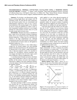
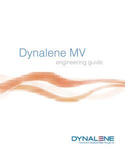
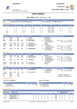
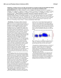
Application Note Heat Transfer Design Team 7 Compact Inverter Jack Grundemann 11142014 Introduction All electrical circuits have resistance in their wires and components. This resistance creates losses that are realized as generated heat. The generated heat can have detrimental effects to circuit performance and needs to be dissipated away from the circuit. In the compact inverter project, the parameters make critical the use of effective heat dissipation. This application note will focus on the design of passive heat sinks, but also cover background on other types of heat dissipation devices as well. Fluid Dynamic Definitions To understand how heat dissipation systems are designed, it is important to have a basic understanding of fluid dynamics. This is the science of liquids and gases in motion. A vast field, this application note will only cover the relevant, high level areas necessary to understanding heat sink design. Defining the properties below will be necessary to understand proper heat sink design: ● Turbulent Flow: A flow regime characterized by chaotic property changes. This includes low momentum diffusion, high momentum convection, and rapid variation of pressure or velocity. ● Laminar Flow: A flow regime characterized by high momentum diffusion and low momentum convection. Occurs when a fluid flows in parallel layers with no disruption between layers. ● Reynolds Number: A dimensionless quantity used to help predict similar fluid flow situations. ○ Laminar flow occurs at low Reynolds numbers, where viscous forces are dominant. ○ Turbulent flow occurs at high Reynolds numbers, where inertial forces are dominant. ● Newtonian Fluid: ● Convection: Movement within a fluid that results in heat transfer. Hotter (less dense) fluids rise and cooler (more dense) fluids fall due to gravity. ● Thermal Conduction: The transfer of internal energy between objects in direct contact with each other. Figure 1, is a diagram depicting the differences in the two types of fluid flow. Figure 1a shows an image of rising smoke showing fluid flow. Heat Sink Introduction A heat sink is a passive heat exchanger that cools an electrical circuit component by dissipating heat into the surrounding environment. In most circuits, the medium heat is exchanged to is air. The most common example of a heat sink is those that are placed on CPUs in computers. The sink in contact with the electrical component has heat transferred to it through thermal conduction. The heat sink increases in temperature as this happens. Convection of the surrounding air is used to transfer heat away from the heat sink and in turn, the primary electrical component. Figure 2 shows a picture of an active fan sink. Active heat sinks are any heat sinks that use forced convection, whereas passive heat sinks use passive convection to dissipate heat. Figure 3 is a diagram of how convection works in a passive heat sink. This shows a heat sink that uses fins to help dissipate heat. There are two designs that are used to maximize the surface area in heat sink: pins or fins. Pins & Fins Maximizing surface area is necessary to increase the effectiveness of passive convection in heat sink design. The primary way a heat sink’s surface area in increased is by the use of fins and pins. These protrusions from the heat sink base allow for ambient air to pass through the gaps between other pins or fins. This ambient air heats up as it travels through these ducts, thereby dissipating the energy from the heat sink. Fins are long straight sections of metal that protrude from the base of the heat sink. Fins often have the best thermal performance and are the lower costing option. However, airflow has to be in the direction of the fins. This work great for systems with laminar flow, but as the Reynolds number increases as heat is transferred from the sink, flow can become turbulent and this can make the fins less efficient. Pins are long, column like sections protruding from the base of the heat sink. These have good performance and a great for unknown/turbulent flows and systems that use natural convection. Typically, they are more expensive but their design is able to handle a wider variety of situations compared to fin designs. Before selecting a heat sink that uses pins or fins, you must first know the type of flow that the system will have. Typically, forced convection systems perform better with a fin design. These are able to handle the typical laminar flows that are seen. If a system has turbulent or unknown flow, it is better to select a pin design. This design works best for natural convection systems. As air convects away heat from the pins, flow will start as laminar. As the air rises, the Reynolds number will increase and cause the flow to become turbulent. Once a protrusion design has been selected based on the type of fluid flow that will be in the system, the next is to know how much heat is dissipated. Numerous performance test will need to be run on a circuit to learn how efficient the circuit is. From this efficiency, you can determine the losses in the circuit. Knowing these losses will allow you to properly determine the sizes and materials used in a heat sink. There are six parameters used in designing the size of a heat sink that need to be taken into consideration (as shown in Figure 4) : the fin spacing, the fin width, the fin height, the fin depth, the base thickness, and the total width. There are many formulas that are used to determine these parameters, but they primarily rely on the ambient temperature, the junction temperature, and the fin material conductivity. The materials that are used in heat sinks are based on how many Watts of heat need to be dissipated. The two materials commonly used are copper and graded aluminum. Copper has a much higher thermal conductivity than aluminum and is used in many applications where space is limited, but large amounts of heat transfer is necessary. Between the heat sink and the electrical component, or heat source, is an air gap (See Figure 5). Air has a very low thermal conductivity and can act as an insulator in certain situations. By inserting a thermal interface between the heat sink and the heat source, thermal conductivity will be increased to dissipate heat more efficiently. There exist several interface types: Graphite, thermal tapes, grease, phase charge materials, and several others. Thermal grease is a very common, highly effective gap filler that is found in many electronics. Many manufacturers of electrical components that generate heat are now coating the outside of their products with high thermal conductive materials like diamond, silver, and gold to help dissipate heat quickly. For most heat sink designs, the addition of thermal grease upon installation is an easy, cost effective option to increase heat transfer. Other Heat Dissipation This application note has talked about the use of passive heat sinks up until this point. Active heat sinks are systems that use forced convection. Examples of these systems are fans, heat pipes, liquid cooling, and peltier devices. Each device works differently and will be briefly explained. A fan creates forced convection of ambient air. This forced convection increases the amount of heat transferred from the heat sink to the ambient air. A heat pipe is a pipe filled with a fluid, generally water. There are two main pipe sections in this closed system, an evaporative section and a condensing section. The fluid has heat transferred to it in the evaporative section. The fluid then flows to a condensing section where the fluid condenses back and dissipates heat to the environment. After, the fluid returns to the evaporative section completing this closed loop system. Liquid cooling systems are similar to heat pipes in that liquids have heat transferred to them, however liquid cooled systems generally don’t rely on natural convection of the fluids in a closed loop system. Pumps are used to circulate the fluids used in the liquid cooled systems. Lastly, peltier devices use thermoelectric cooling to conduct heat away from the source. This is done using a semiconductive material to create a doped, solid state heat pump. Most forced convection systems require the input of additional energy to perform properly. Conclusion & How it Relates to Group 7 Group seven’s technical project for ECE 480 is to create a compact power inverter. Due to the size constraints of the project, operation temperatures must be kept low. After significant research, the best way discovered to mitigate heat was with a passive heat sink. This decision was based on several factors: ● Unknown and turbulent flow inside an enclosure ● Size constraints of circuit. Addition of components of an active heat sink would require more volume. ● The cost of other systems while effective would not fit into the budget. The finalized passive heat sink used in the design will References

© Copyright 2026