
APPROVED DOCUMENT
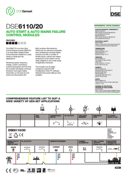
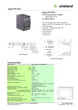
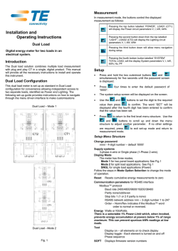
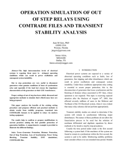
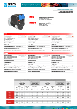
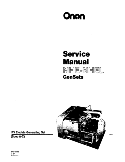
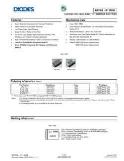
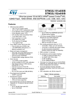
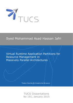
PI144G - Winding 17
APPROVED DOCUMENT
Technical Data Sheet
PI144G
SPECIFICATIONS & OPTIONS
TERMINALS & TERMINAL BOX
Stamford industrial generators meet the requirements of
BS EN 60034 and the relevant section of other
international standards such as BS5000, VDE 0530,
NEMA MG1-32, IEC34, CSA C22.2-100, AS1359.
Other standards and certifications can be considered on
request.
VOLTAGE REGULATOR
Standard generators are 3-phase reconnectable with 12
ends brought out to the terminals, which are mounted at
the non-drive end of the generator. Dedicated single
phase generators are also available. A sheet steel
terminal box contains provides ample space for the
customers' wiring and gland arrangements. Alternative
terminal boxes are available for customers who want to fit
additional components in the terminal box.
AS480 AVR fitted as STANDARD
SHAFT & KEYS
With this self-excited system the main stator provides
power via the AVR to the exciter stator. The high
efficiency semi-conductors of the AVR ensure positive
build-up from initial low levels of residual voltage.
The exciter rotor output is fed to the main rotor through a
three-phase full-wave bridge rectifier. The rectifier is
protected by a surge suppressor against surges caused,
for example, by short circuit or out-of-phase paralleling.
The AS480 will support limited accessories, RFI
suppession remote voltage trimmer and for the P1 range
only a 'droop' Current Transformer (CT) to permit parallel
operation with other ac generators.
The AVR is can be fitted to either side of the generator in
its own housing in the non-drive end bracket.
All generator rotors are dynamically balanced to better
than BS6861:Part 1 Grade 2.5 for minimum vibration in
operation. Two bearing generators are balanced with a
half key.
Excitation Boost System (EBS) (OPTIONAL)
The EBS is a single, self-contained unit, attached to the
non-drive end of the generator.
The EBS unit consists of the Excitation Boost Controller
(EBC) and an Excitation Boost Generator (EBG). Under
fault conditions, or when the generator is subjected to a
large impact load such as a motor starting, the generator
voltage will drop. The EBC senses the drop in voltage
and engages the output power of the EBG. This
additional power feeds the generator’s excitation system,
supporting the load until breaker discrimination can
remove the fault or enable the generator to pick up a
motor and drive the voltage recovery.
APPROVED DOCUMENT
STANDARDS
INSULATION / IMPREGNATION
The insulation system is class 'H'.
All wound components are impregnated with materials and
processes designed specifically to provide the high build
required for static windings and the high mechanical
strength required for rotating components.
QUALITY ASSURANCE
Generators
are
manufactured
using
production
procedures having a quality assurance level to BS EN ISO
9001.
The stated voltage regulation may not be maintained in
the presence of certain radio transmitted signals. Any
change in performance will fall within the limits of Criteria
'B' of EN 61000-6-2:2001. At no time will the steady-state
voltage regulation exceed 2%.
DE RATES
All values tabulated on page 6 are subject to the following
reductions
5% when air inlet filters are fitted.
3% for every 500 metres by which the operating altitude
exceeds 1000 metres above mean sea level.
3% for every 5°C by which the operational ambient
temperature exceeds 40°C.
Note: Requirement for operating in an ambient exceeding
60°C must be referred to the factory.
WINDINGS & ELECTRICAL PERFORMANCE
All generator stators are wound to 2/3 pitch. This
eliminates triplen (3rd, 9th, 15th …) harmonics on the
voltage waveform and is found to be the optimum design
for trouble-free supply of non-linear loads. The 2/3 pitch
design avoids excessive neutral currents sometimes
seen with higher winding pitches, when in parallel with
the mains. A fully connected damper winding reduces
oscillations during paralleling. This winding, with the 2/3
pitch and carefully selected pole and tooth designs,
ensures very low waveform distortion.
5% For reverse rotation
(Standard rotation CW when viewed from DE)
NB Continuous development of our products entitles us
to change specification details without notice, therefore
they must not be regarded as binding.
Front cover drawing typical of product range.
2
PI144G
WINDING 17
CONTROL SYSTEM
STANDARD AS480 AVR (SELF EXCITED)
VOLTAGE REGULATION
± 1.0 %
SUSTAINED SHORT CIRCUIT
SELF EXCITED MACHINES DO NOT SUSTAIN A SHORT CIRCUIT CURRENT
CONTROL SYSTEM
AS480 AVR WITH OPTIONAL EXCITATION BOOST SYSTEM (EBS)
SUSTAINED SHORT CIRCUIT
REFER TO SHORT CIRCUIT DECREMENT CURVE (page 5)
CLASS H
INSULATION SYSTEM
IP23
PROTECTION
0.8
RATED POWER FACTOR
DOUBLE LAYER CONCENTRIC
STATOR WINDING
WINDING PITCH
TWO THIRDS
WINDING LEADS
12
STATOR WDG. RESISTANCE
0.306 Ohms PER PHASE AT 22°C SERIES STAR CONNECTED
ROTOR WDG. RESISTANCE
0.857 Ohms at 22°C
EXCITER ROTOR RESISTANCE
EBS STATOR RESISTANCE
R.F.I. SUPPRESSION
APPROVED DOCUMENT
EXCITER STATOR RESISTANCE
20.3 Ohms at 22°C
0.201 Ohms PER PHASE AT 22°C
12.9 Ohms at 22°C
BS EN 61000-6-2 & BS EN 61000-6-4,VDE 0875G, VDE 0875N. refer to factory for others
NO LOAD < 1.5% NON-DISTORTING LINEAR LOAD < 5.0%
WAVEFORM DISTORTION
MAXIMUM OVERSPEED
BEARING DRIVE END
BEARING NON-DRIVE END
2250 Rev/Min
BALL. 6309-2RS (ISO)
BALL. 6306-2RS (ISO)
1 BEARING
WITH EBS
WEIGHT COMP. GENERATOR
160 kg
WEIGHT WOUND STATOR
68 kg
WEIGHT WOUND ROTOR
57.39 kg
WR² INERTIA
SHIPPING WEIGHTS in a crate
PACKING CRATE SIZE
TELEPHONE INTERFERENCE
COOLING AIR
VOLTAGE SERIES STAR
0.2196 kgm
178 kg
2
2 BEARING
WITHOUT EBS
WITH EBS
WITHOUT EBS
158.3 kg
163 kg
161.3 kg
68 kg
68 kg
68 kg
55.68 kg
0.2179 kgm
58.39 kg
2
0.2198 kgm
176.3 kg
0.2181 kgm2
187 kg
185.3 kg
85 x 51 x 67 (cm)
85 x 51 x 67 (cm)
THF<2%
TIF<50
kVA BASE RATING FOR REACTANCE
VALUES
0.122 m³/sec 251 cfm
600
37.5
Xd DIR. AXIS SYNCHRONOUS
1.9
X'd DIR. AXIS TRANSIENT
0.17
X''d DIR. AXIS SUBTRANSIENT
0.13
Xq QUAD. AXIS REACTANCE
0.90
X''q QUAD. AXIS SUBTRANSIENT
0.19
XL LEAKAGE REACTANCE
0.07
X2 NEGATIVE SEQUENCE
0.16
X0 ZERO SEQUENCE
0.07
REACTANCES ARE SATURATED
56.69 kg
2
VALUES ARE PER UNIT AT RATING AND VOLTAGE INDICATED
T'd TRANSIENT TIME CONST.
0.024 s
T''d SUB-TRANSTIME CONST.
0.006 s
T'do O.C. FIELD TIME CONST.
0.55 s
Ta ARMATURE TIME CONST.
0.007 s
SHORT CIRCUIT RATIO
1/Xd
3
PI144G
Winding 17
Locked Rotor Motor Starting Curves
AS480 AVR Without EBS
600V
30
.
25
15
10
5
0
0
10
20
30
40
APPROVED DOCUMENT
PER CENT TRANSIENT VOLTAGE DIP
20
50
60
70
80
90
100
LOCKED ROTOR kVA
AS480 AVR With EBS
30
.
25
600V
PER CENT TRANSIENT VOLTAGE DIP
20
15
10
5
0
0
10
20
30
40
50
60
LOCKED ROTOR kVA
4
70
80
90
100
110
PI144G
Winding 17
THREE PHASE EFFICIENCY CURVES
APPROVED DOCUMENT
Three-phase Short Circuit Decrement Curve. No-load Excitation at Rated Speed
Based on star (wye) connection.
WITH EBS FITTED
CURRENT (Amps)
1000
100
10
0.001
0.01
SYMMETRICAL
ASYMMETRICAL
0.1
TIME (secs)
1
10
Sustained Short Circuit = 160 Amps
Note
The following multiplication factor should be used to convert the values from curve for the
various types of short circuit :
3-phase
2-phase L-L 1-phase L-N
Instantaneous
x 1.00
Minimum
x 1.00
x 1.00
Sustained
10 sec.
Max. sustained duration
All other times are unchanged
5
x 0.87
x 1.30
x 1.80
x 3.20
x 1.50
x 2.50
5 sec.
2 sec.
PI144G
Winding 17 / 0.8 Power Factor
60Hz
RATINGS
Cont. F - 105/40°C
Cont. H - 125/40°C
Standby - 150/40°C
Standby - 163/27°C
Series Star (V)
600
600
600
600
Parallel StarStar (V)
300
300
300
300
Series Delta (V)
346
346
346
346
kVA
33.8
37.5
39.4
40.9
kW
27.0
30.0
31.5
32.7
Efficiency (%)
89.5
89.2
89.0
88.8
kW Input
30.2
33.6
35.4
36.8
Class - Temp Rise
APPROVED DOCUMENT
DIMENSIONS
6
APPROVED DOCUMENT
Head Office Address:
Barnack Road, Stamford
Lincolnshire, PE9 2NB
United Kingdom
Tel: +44 (0) 1780 484000
Fax: +44 (0) 1780 484100
www.cumminsgeneratortechnologies.com
Copyright 2010, Cummins Generator Technologies Ltd, All Rights Reserved
Stamford and AvK are registered trade marks of Cummins Generator Technologies Ltd
Cummins and the Cummins logo are registered trade marks of Cummins Inc.
PI144G-17-TD-EN-SG-A

© Copyright 2026