
Descarga el catálogo comercial
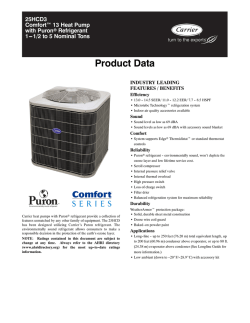
38CKD (60 Hz)
13 SEER Air Conditioner
Export Model
Sizes 018 --- 060
Product Data
FEATURES AND BENEFITS
AVAILABLE SIZES:
Nominal sizes are available from 018 through 060 to meet the
needs of residential and light commercial applications.
CERTIFICATION:
All models are listed with UL and NOM.
ELECTRICAL RANGE:
Units offered in single phase 208/230v are 018--060 and three
phase 208/230v in 036, 048 and 060.
FAN MOTOR:
The totally enclosed fan motor provides greater reliability under
adverse conditions and dependable performance for many years.
The permanent split capacitor type motor was designed for
optimum efficiency. The motor was then qualified under extreme
conditions to help ensure a long, reliable life.
CABINET:
A weather protective cabinet of prepainted steel is protected
underneath by a galvanized coating and treated with a layer of zinc
phosphate for a finish that will last for many years. All screws on
cabinet exterior are coated for a long--lasting, rust--resistant, quality
appearance.
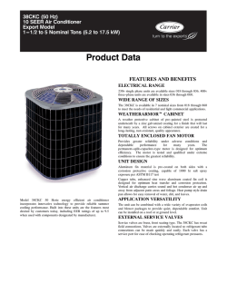
UNIT DESIGN:
The copper tube, enhanced sine wave, aluminum fin coil is
designed for optimum heat transfer. Vertical air discharge carries
sound and hot condenser air up and away from adjacent patio areas
and foliage. The base pan is designed for easy removal of water,
dirt, and leaves.
COMPRESSOR:
Each compressor is protected with internal temperature-- and
current--sensitive overloads. An internal pressure relief valve
provides high pressure protection to the refrigerant system. For
improved serviceability, all models are equipped with a compressor
terminal plug.
SERVICE VALVES:
Both service valves are brass, front seating type with sweat
connections. Valves are externally located so refrigerant tube
connections can be made quickly and easily. Each valve has a
service port for ease of checking operating refrigerant pressures.
SERVICEABILITY:
One access panel provides access to electrical controls. Removal of
top gives access to fan motor, compressor, and condenser coil.
PRODUCT NUMBER NOMENCLATURE
38CKD
3
18
M
3
A
1
Model
3 = 13 SEER
Nominal Capacity
18 --- 1 ---1/2 Ton
24 --- 2 Tons
30 --- 2 ---1/2 Tons
36 --- 3 Tons
42 --- 3 ---1/2 Tons
48 --- 4 Ton
60 --- 5 Ton
Packaging
Series
Electrical Supply
3=208/230 ---1
5=208/230 ---3
38CKD
M = NOM Certified
— = Standard
ISO 9001:2000
REGISTERED
2
3
8.3
40.3
0.5
10.9
14
72 / 68
(23.2 / 20.7)
15
318
B
10.8
56.3
.05
14.0
14
56/54
(17.1 / 16.5)
20
208/230—60—1
324
B
187—253
13.5
68.3
0.8
17.7
14
44 / 42
(13.4 / 12.8)
30
330
B
10.8
73.0
1.1
14.6
14
52 / 50
(15.9 / 15.2)
20
208/230--- 60--- 3
Copeland
Scroll
Internal Line Break
336
B
KAACH1201AAA
KH43LZ034
KSATX0701HSO
KSASH0601COP
HC40GE226
N/A
N/A
3400
3400
KAACS0201PTC
KSAHS1501AAA
23.79
1/4 PSC and 1100
38CKD
15.4
114.0
1.4
20.7
12
60 / 63
(18.3 / 19.2)
30
N/A
N/A
KSATX1001HSO
KSASH2101COP
KAACS0201PTC
KSAHS1701AAA
3400
19.47
R--- 22 10.52 (4.79)
25.3
146.0
1.4
33.0
8
94 / 90
(28.7 / 27.4)
50
208/230--- 60--- 3
360
B
208/230--- 60--- 1
1--- 1/8 and 3/8
208/230--- 60--- 3
187--- 253
12.8
98.0
1.4
17.4
14
44 / 42
(13.4 / 12.8)
25
R--- 22 8.88 (4.04)
20.2
137.0
1.4
26.7
10
74 / 70
(22.6 / 21.3)
40
208/230--- 60--- 1
348
B
17.3
R--- 22 7.01 (3.18)
19.2
112.0
1.4
25.4
10
77 / 73
(23.5 / 22.3)
40
208/230--- 60--- 1
342
B
# Requires ball--- bearing fan motor.
NOTES:
1. Control circuit is 24v on all units and requires external power source.
2. All motors/compressors contain internal overload protection.
3. Copper wire must be used from service disconnect to unit.
TSTATXXPBP01
TSTATXXBBP01
TSTATCCSEN01--- B
TB--- PAC01
TB--- NAC01
KAALS0101LLS
KAATD0101TDR
KSALA0201R22
KAAWS0101AAA
KAAFT0101AAA
KSACY0101AAA
N/A
N/A
KSALA0601AAA
HC38GE219
KAALP0101LPS
KSAHI0101HPS
12.98
1/5 PSC and 1100
208/230—60—1
3100
7/8 and 3/8
R--- 22 5.35 (2.43)
15.4
87.0
1.1
20.4
12
60 / 57
(18.3 / 17.4)
30
208/230--- 60--- 1
Max Branch Circuit Fuse Size†
COMPRESSOR AND REFRIGERANT
Compressor—Manufacturer
Type
Temperature and Current Protection
R--- 22 Refrigerant—
R--- 22 3.56 (1.62)
R--- 22 4.08 (1.85)
R--- 22 4.11 (1.87)
Amount Lb (kg) @ 15 ft (4.6 m)
Refrigerant Tubes (In. OD)
3/4 and 3/8
}} Rated Vapor and Liquid
CONDENSER COIL AND FAN
Coil Face Area (Sq Ft)
8.4
9.8
9.8
Fan Motor—HP, Type, and RPM
1/12 PSC and 1100
1/10 PSC and 1100
Volts—Hertz—Phase
Condenser Airflow (CFM)
1700
1700
2000
OPTIONAL EQUIPMENT
Cycle Protector
Start Assist—PTC Type
KAACS0201PTC
Start Assist—Capacitor/Relay Type
KSAHS1501AAA
MotorMaster Control
Ball Bearing Fan Motor (RCD)
HC32GE234
HC34GE239
Low--- Pressure Switch
High--- Pressure Switch
Compressor Sound Hood
KSASH1801COP
Time--- Delay Relay
Low--- Ambient Pressure Switch Kit
Winter Start Control
Evaporator Freeze Thermostat
Compressor Crankcase Heater
KAACH1401AAA
Liquid Line Solenoid Valve††
TXV (Hard Shutoff)††
KSATX0601HSO
Standard Thermostat, Manual Changeover, Non--- Programmable, F/C,
1--- Stage Heat, 1--- Stage Cool
Thermostat, Auto Changeover, 7--- Day
Programmable, F/C, 1--- Stage Heat,
1--- Stage Cool
Outdoor Sensor
Liquid Line Filter Drier
KH43LZ036
Backplate for Standard Thermostat
Backplate for Programmable
Thermostat
N/A --- Not applicable in this application.
* Permissible limits of the voltage range at which unit will operate satisfactorily. Operation outside these limits may result in unit
failure.
{ Time--- delay fuse or circuit breaker.
} Length shown is as measured 1 way along wire path between unit and service panel for voltage drop not to exceed 2%.
** If wire is applied at ambient greater than 30° C, consult Table 310--- 16 of the NEC (NFPA 70). The ampacity of
nonmetallic--- sheathed cable (NM), trade name ROMEX, shall be that of 60° C conductors, per the NEC (NFPA 70) Article
336--- 26.
{{ Do not use hard shutoff TXV with liquid solenoid valve.
}} Units are rated with 25 ft (7.6 m) of lineset length. See Vapor Line Sizing and Cooling Capacity Loss table when using other
sizes and lengths of lineset.
Max Wire Length (60/75) ft (m)‡
UNIT SIZE
SERIES
ELECTRICAL
Unit Volts—Hertz—Phase
Operating Voltage Range*
Compressor—Rated Load Amps
Locked Rotor Amps
Condenser Fan Motor— Full Load Amps
Min Unit Ampacity for Wire Sizing
Min Wire Size (60/75 Copper) AWG**
SPECIFICATIONS
4
X
X
X
X
38CKD336-M
38CKD342-M
38CKD348-M
38CKD360-M
36,42,48,60
--
X
X
O
X
O
3 1/2"
O
O
O
O
O
O
O
3/8"
35" X 35"
31 1/2" X 31 1/2"
26" X 26"
23 1/2" X 23 1/2"
MINIMUM
MOUNTING PAD
DIMENSIONS
DVAPOR LINE CONN.
C
LIQUID LINE CONN.
FIELD CONTROL SUPPLY CONN.
7/8" HOLE
18,24,30
--
O
O
O
O
O
O
FIELD POWER SUPPLY CONN.
7/8" HOLE WITH
1 1/8" KNOCKOUT AND
1 3/8" KNOCKOUT
UNIT SIZE
B
O
X
38CKD330-M
O
X
38CKD324-M
O
X
208-230-1-60
ELECTRICAL
CHARACTERISTICS
230-1-60
38CKD318-M
SERIES
208/230-3-60
UNIT
DIMENSIONS -- ENGLISH
460-3-60
24 13/16"
28 7/16"
28 7/16"
24 13/16"
31 13/16"
42"
35 3/16"
23 1/8"
23 1/8"
23 1/8"
31 3/16"
31 3/16"
31 3/16"
31 3/16"
X = YES
O = NO
B
A
SQ.
D
7/8"
7/8"
7/8"
7/8"
3/4"
3/4"
3/4"
AIR DISCHARGE
A
3 7/8"
3 7/8"
3 7/8"
3 7/8"
3 3/4"
3 3/4"
3 3/4"
C
6 9/16"
6 9/16"
6 9/16"
6 9/16"
4 7/16"
4 7/16"
4 7/16"
E
24 11/16"
24 11/16"
24 11/16"
24 11/16"
18 1/16"
18 1/16"
18 1/16"
F
1 7/8"
9 1/8"
9 1/8"
9 1/8"
9 1/8"
P
7 13/16"
7 13/16"
7 13/16"
G
3"
AIR IN
2 15/16"
2 15/16"
2 15/16"
2 15/16"
2 13/16"
2 13/16"
2 13/16"
K
5/16"
L
5/8"
5/8"
5/8"
5/8"
1/2"
1/2"
1/2"
L
16"
16"
16"
16"
12"
12"
12"
M
K
G
M
15 1/2"
15 1/2"
15 1/2"
15 1/2"
11 3/4"
11 3/4"
11 3/4"
N
15 1/4"
17"
13 3/4"
11 5/8 "
12 7/8"
12/1/2"
11 7/8"
P
3/8" TIEDOWN KNOCKOUTS
(2) PLACES
AIR
DISCHARGE
E
N
F
5. ALL DIMENSIONS ARE IN "INCHES" UNLESS NOTED.
4. CENTER OF GRAVITY .
3. SERIES DESIGNATION IS THE 13TH POSITION OF THE
UNIT MODEL NUMBER.
AIR IN
32 3/16" X 32 3/16" X 37 7/16"
32 3/16" X 32 3/16" X 44 1/4"
32 3/16" X 32 3/16" X 34"
32 3/16" X 32 3/16" X 27 3/16"
24 1/8" X 24 1/8" X 30 5/8"
24 1/8" X 24 1/8" X 30 5/8"
24 1/8" X 24 1/8" X 27 3/16"
2. MINIMUM OUTDOOR OPERATING AMBIENT IN COOLING
MODE IS 55
F, MAX. 125
F.
AIR IN
AIR IN
233.0
208.0
188.0
157.0
126.5
123.0
120.0
SHIPPING
DIMENSIONS (L x W x H)
1. ALLOW 30" CLEARANCE TO SERVICE SIDE OF UNIT,
48" ABOVE UNIT, 6" ON ONE SIDE, 12" ON REMAINING SIDE,
AND 24" BETWEEN UNITS FOR PROPER AIRFLOW.
NOTES:
208.0
174.0
164.5
135.0
112.5
108.5
105.0
OPERATING
SHIPPING
WEIGHT (LBS) WEIGHT (LBS)
38CKD
5
X
X
X
X
38CKD336-M
38CKD342-M
38CKD348-M
38CKD360-M
--
36,42,48,60
88.9
X
X
O
X
O
O
O
9.53
889.0 X 889.0
800.1 X 800.1
660.4 X 660.4
596.9 X 596.9
MINIMUM
MOUNTING PAD
DIMENSIONS
DVAPOR LINE CONN.
C
LIQUID LINE CONN.
FIELD CONTROL SUPPLY CONN.
22.23 HOLE
18,24,30
--
O
O
O
O
FIELD POWER SUPPLY CONN.
22.23 HOLE WITH
28.58 KNOCKOUT AND
34.93 KNOCKOUT
UNIT SIZE
B
O
X
38CKD330-M
O
X
38CKD324-M
O
X
208-230-1-60
722.3
722.3
630.2
808.0
1066.8
893.8
587.4
587.4
792.2
792.2
792.2
792.2
X = YES
O = NO
O
O
O
O
O
A
SQ.
98.4
98.4
98.4
98.4
95.2
95.2
95.2
C
AIR DISCHARGE
630.2
587.4
O
O
B
A
ELECTRICAL
CHARACTERISTICS
230-1-60
38CKD318-M
SERIES
208/230-3-60
UNIT
DIMENSIONS --SI
460-3-60
22.2
22.2
22.2
22.2
19.0
19.0
19.0
D
166.7
166.7
166.7
166.7
112.7
112.7
112.7
E
47.6
627.1
627.1
627.1
627.1
458.8
458.8
458.8
F
P
231.8
231.8
231.8
231.8
198.4
198.4
198.4
G
76.2
AIR IN
L
74.6
74.6
74.6
74.6
71.4
71.4
71.4
K
8.0
15.9
15.9
15.9
15.9
12.7
12.7
12.7
L
K
G
406.4
406.4
406.4
406.4
304.8
304.8
304.8
M
M
393.7
393.7
393.7
393.7
298.4
298.4
298.4
N
94.3
105.7
94.3
85.3
71.2
57.4
55.8
54.4
9.53 TIEDOWN KNOCKOUTS
(2) PLACES
AIR
DISCHARGE
E
N
5. ALL DIMENSIONS ARE IN "MM" UNLESS NOTED.
4. CENTER OF GRAVITY .
F
3. SERIES DESIGNATION IS THE 13TH POSITION OF THE
UNIT MODEL NUMBER.
2. MINIMUM OUTDOOR OPERATING AMBIENT IN COOLING
MODE IS 13
C, MAX. 52
C.
AIR IN
817.6 X 817.6 X 950.9
817.6 X 817.6 X 1124.0
817.6 X 817.6 X 863.6
817.6 X 817.6 X 690.6
612.8 X 612.8 X 777.9
612.8 X 612.8 X 777.9
612.8 X 612.8 X 690.6
SHIPPING
DIMENSIONS (L x W x H)
1. ALLOW 762.0 CLEARANCE TO SERVICE SIDE OF UNIT,
1219.2 ABOVE UNIT, 152.4 ON ONE SIDE, 304.8 ON REMAINING SIDE,
AND 609.6 BETWEEN UNITS FOR PROPER AIRFLOW.
NOTES:
78.9
74.6
61.2
51.0
49.2
47.6
OPERATING
SHIPPING
WEIGHT (Kgs) WEIGHT (Kgs)
38CKD
AIR IN
AIR IN
387.4
431.8
349.2
295.3
327.0
317.5
301.6
P
38CKD
OPTIONAL EQUIPMENT USAGE GUIDELINE
ACCESSORY
REQUIRED FOR LOWMBIENT
COOLING APPLICATIONS
(Below 55F / 22.8C)
REQUIRED FOR
LONG LINE
APPLICATIONS*
(Over 80 Ft./24.4 m)
REQUIRED FOR
SEA COAST
APPLICATIONS
(Within 2 miles/3.2 km)
Ball Bearing Fan Motor
Yes{
No
No
Compressor Start Assist Capacitor and Relay
Yes
Yes
No
Crankcase Heater
Yes
Yes
No
Evaporator Freeze Thermostat
Yes
No
No
Hard Shut---Off TXV
Yes
Yes
Yes
Liquid Line Solenoid Valve
No
See Long --- Line Application Guideline
No
Low Ambient Kit (Pressure Switch)
Yes
No
No
Support Feet
Recommended
No
Recommended
Winter Start Control
Yes
No
No
* For tubing line sets between 80 and 200 ft. (24.38 and 60.96 m) and/or 20 ft. (6.09 m) vertical differential, refer to Residential Split---System Longline
Application Guideline.
{ Required for Low---Bmbient Controller (full modulation feature) MotorMasterr Control.
Accessory Description and Usage (Listed Alphabetically)
1. Ball--Bearing Fan Motor
A fan motor with ball bearings which permits speed reduction
while maintaining bearing lubrication.
Usage Guideline:
Required on all units when MotorMasterr is used.
2. Compressor Start Assist -- Capacitor and Relay
Start capacitor and relay gives a ”hard” boost to compressor motor
at each start up.
Usage Guideline:
Required for reciprocating compressors in the
following applications:
Long line
Low ambient cooling
Hard shut off expansion valve on indoor coil
Liquid line solenoid on indoor coil
Required for single--phase scroll compressors in the
following applications:
Long line
Low ambient cooling
Suggested for all compressors in areas with a history of
low voltage problems.
3. Compressor Start Assist — PTC Type
Solid state electrical device which gives a ”soft” boost to the
compressor at each start--up.
Usage Guideline:
Suggested in installations with marginal power supply.
4. Crankcase Heater
An electric resistance heater which mounts to the base of the
compressor to keep the lubricant warm during off cycles. Improves
compressor lubrication on restart and minimizes the chance of
liquid slugging.
Usage Guideline:
Required in low ambient cooling applications.
Required in long line applications.
Suggested in all commercial applications.
5. Cycle Protector
The cycle protector is designed to prevent compressor short
cycling. This control provides an approximate 5--minute delay after
power to the compressor has been interrupted for any reason,
including power outage, protector control trip, thermostat jiggling,
or normal cycling.
6. Evaporator Freeze Thermostat
An SPST temperature--Bctuated switch that stops unit operation
when evaporator reaches freeze--up conditions.
Usage Guideline:
Required when low ambient kit has been added.
7. Low--Bmbient Pressure Switch Kit
A long life pressure switch which is mounted to outdoor unit
service valve. It is designed to cycle the outdoor fan motor in order
to maintain head pressure within normal operating limits
(approximately 100 psig/689.5 KpA to 225 psig/1551.3 KpA. The
control will maintain working head pressure at low--Bmbient
temperatures down to 0_F (--18_C)when properly installed.
Usage Guideline:
A Low--Bmbient Pressure Switch or MotorMasterr
Low--Bmbient Controller must be used when cooling operation is
used at outdoor temperatures below 55_F (12.8_C).
8. MotorMasterr Low--Bmbient Controller
A fan--speed control device activated by a temperature sensor,
designed to control condenser fan motor speed in response to the
saturated, condensing temperature during operation in cooling
mode only. For outdoor temperatures down to --20_F (--28.9_C), it
maintains condensing temperature at 100_F 10_F (37.8_C
5.5_C).
Usage Guideline:
A MotorMasterr Low Ambient Controller or
Low--Bmbient Pressure Switch must be used when
cooling operation is used at outdoor temperatures
below 55_F (12.8_C).
Suggested for all commercial applications.
9. Outdoor Air Temperature Sensor
Designed for use with Carrier Thermostats listed in this
publication. This device enables the thermostat to display the
outdoor temperature. This device also
is required to enable special thermostat features such as auxiliary
heat lock out.
Usage Guideline:
Suggested for all Carrier thermostats listed in this
publication.
6
Accessory Description and Usage (Listed Alphabetically) (Continued)
13. Time--Delay Relay
An SPST delay relay which briefly continues operation of indoor
blower motor to provide additional cooling after the compressor
cycles off.
NOTE: Most indoor unit controls include this feature. For those
that do not, use the guideline below.
Usage Guideline:
For improved efficiency ratings for certain
combinations of indoor and outdoor units. Refer to
ARI Unitary Directory.
14. Winter Start Control
This control is designed to alleviate nuisance opening of the
low--pressure switch by bypassing it for the first 3 minutes of
operation.
38CKD
10. Sound Hood
Wraparound sound reducing cover for the compressor. Reduces the
sound level by about 2 dBA.
Usage Guideline:
Suggested when unit is installed closer than 15 ft (4.57 m) to
quiet areas, bedrooms, etc.
Suggested when unit is installed between two houses less
than 10 ft (3.05 m) apart.
11. Support Feet
Four stick--on plastic feet that raise the unit 4 in. (101.6 mm) above
the mounting pad. This allows sand, dirt, and other debris to be
flushed from the unit base, minimizing corrosion.
Usage Guideline:
Suggested in the following applications:
Coastal installations.
Windy areas or where debris is normally circulating.
Rooftop installations.
For improved sound ratings.
12. Thermostatic Expansion Valve (TXV)
A modulating flow--Bontrol valve which meters refrigerant liquid
flow rate into the evaporator in response to the superheat of the
refrigerant gas leaving the evaporator.
Kit includes valve, adapter tubes, and external equalizer tube. Hard
shut off types are available.
NOTE: When using a hard shut off TXV with single phase
reciprocating compressors, a Compressor Start Assist Capacitor
and Relay is required.
Usage Guideline:
Required to achieve ARI ratings in certain equipment
combinations. Refer to combination ratings.
Hard shut off TXV or LLS required in air conditioner
long line applications.
Required for use on all zoning systems.
7
A--WEIGHTED SOUND POWER LEVEL
Unit Sise
318---B
324---B
330---B
336---B
342---B
348---B
360---B
Standard
Rating (dBA)
76
76
77
76
80
80
80
125
52.5
52
53
59
60
65
63.5
TYPICAL OCTAVE BAND SPECTRUM (dBA without tone adjustment)
250
500
1000
2000
4000
60
63.5
67
64
60
58.5
64
67.5
64
60
60.5
70.5
73
66
62
66.5
70
70.5
68
65
67.5
71.5
75
71
67.5
67
71.5
74.5
70.5
69
68.5
72
73
72.5
70.5
8000
57
55
60.5
59
62
65.5
68
Note: Tested in accordance with ARI standard 270.95 (Not listed with ARI)
38CKD
METERING DEVICE
UNIT SIZE ---SERIES
318---B
324---B
330---B
336---B
342---B
348---B
360---B
INDOOR
REQUIRED SUB---BOOLING F (C)
8 (4.4)
TXV*
10 (5.6)
* TXV must be ordered separately when indoor coil is not equipped with a TXV. TXV must be hard---shutoff type.
RECOMMENDED TUBE DIAMETERS
UNIT SIZE
318, 324, 330
336, 342
348, 360
TUBE LENGTH ft (m)*
LIQUID TUBE DIAMETER (In.)
0 to 80
(0 to 24.38)
3/8
VAPOR TUBE DIAMETER (In.)
3/4
7/8
1--- 1/8
* For tube set over 80 ft (24.4 m) horizontal and/or 20 ft (6.10 m) vertical differential, consult Residential Split System Long---Line Application Guidelines.
8
RATINGS AND PERFORMANCE
38CKD318--- M--- 3B
38CKD324--- M--- 3B
38CKD330--- M--- 3B
38CKD036--- M--- (3,5)B
38CKD042--- M--- 3B
38CKD048--- M--- (3,5)B
38CKD060--- M--- (3,5)B
Indoor
*CAP**2414**
FB4CNF018
FB4CNF024
FB4BNL024
*CAP**3014**
FB4CNF024
FB4CNF030
FB4BNL024
*CAP**3617**
FB4CNF030
FB4CNF036
FB4BNL036
*CAP**4221**
FB4CNF036
FB4CNF042
FB4BNL036
*CAP**4821**
FB4CNF042
FB4CNF048
FB4BNL048
*CAP**6024**
FB4CNF048
FB4CNF060
FB4BNL048
FB4BNL060
*CAP**6024**
FB4CNF060
FB4BNL060
Capacity
17,000
17,500
17,500
17,000
23,000
23,400
24,000
23,000
28,000
28,400
28,400
28,000
34,000
35,400
36,000
35,000
40,000
42,000
42,000
41,000
46,000
48,000
48,000
48,000
48,000
57,000
58,500
58,500
AHRI Standard Ratings
Cooling
Factory
SEER
Enhancement{
TDR
TXV
13.0
TDR
TDR
TDR
TXV
13.0
TDR
TDR
TDR
TXV
13.0
TDR
TDR
TDR
TXV
13.0
TDR
TDR
TDR
TXV
13.0
TDR
TDR
TDR
TXV
13.0
TDR
TDR
TDR
TDR
TXV
13.0
TDR
TDR
TXV
13.0
13.0
12.0
13.0
13.0
12.0
13.0
13.0
12.0
13.0
13.0
12.0
13.0
13.0
12.0
13.0
13.0
12.0
12.0
13.0
12.0
EER
11.0
11.0
11.0
10.0
11.0
11.0
11.0
10.0
11.0
11.0
11.0
10.0
11.0
11.0
11.0
10.0
11.0
11.0
11.0
10.0
11.0
11.0
11.0
10.0
10.0
11.0
11.0
10.0
* Tested Combination
{ All indoor models must be installed with an R---22 TXV
EER --- Energy Efficiency Ratio
SEER --- Seasonal Energy Efficiency Ratio
NOTES:
1. Ratings are net values reflecting the effects of circulating fan motor heat. Supplemental electric heat is not included.
2. Tested outdoor/indoor combinations have been tested in accordance with DOE test procedures for central air conditioners. Ratings for other combinations
are determined under DOE computer simulation procedures.
3. Determine actual CFM values obtainable for your system by referring to fan performance data in fan coil or furnace coil literature.
4. Minimum outdoor operating ambient in cooling mode is 55_F (12.8_C), maximum 115_F (46.1_C).
9
38CKD
Unit Size --- Series
Model+
10
72 (22.2)
67 (19.4)
62 (16.7)
57 (13.9)
72 (22.2)
67 (19.4)
62 (16.7)
57 (13.9)
72 (22.2)
67 (19.4)
62 (16.7)
57 (13.9)
72 (22.2)
67 (19.4)
62 (16.7)
57 (13.9)
72 (22.2)
67 (19.4)
62 (16.7)
57 (13.9)
72 (22.2)
67 (19.4)
62 (16.7)
57 (13.9)
See notes on pg. 13
900
800
700
CFM
EWB
° F (° C)
EVAPORATOR AIR
675
600
525
CFM
EWB
° F (° C)
EVAPORATOR AIR
10.53
12.81
15.06
16.03
11.08
13.68
16.24
16.80
11.60
14.51
17.26
17.45
Sens‡
1.24
1.26
1.28
1.28
1.27
1.29
1.30
1.30
1.29
1.31
1.32
1.33
Sys.
Power
KW**
26.67
24.32
22.38
21.96
27.10
24.73
22.92
22.81
27.41
25.04
23.51
23.51
Total
13.57
16.76
19.95
21.96
14.26
17.87
21.38
22.81
14.90
18.92
23.51
23.51
1.71
1.69
1.68
1.67
1.75
1.74
1.72
1.72
1.79
1.78
1.77
1.77
Sys.
Power
KW**
85 (29.4
Sens‡
85 (29.4
25.79
23.53
21.68
21.39
26.18
23.91
22.20
22.19
26.45
24.19
22.85
22.85
Total
38CKD324--- B Outdoor Section With *CAP**3014A** Indoor Section
13.26
1.88
24.83
12.92
2.07
16.45
1.86
22.66
16.11
2.05
19.63
1.84
20.89
19.25
2.03
21.39
1.84
20.72
20.72
2.03
13.94
1.92
25.18
13.59
2.11
17.55
1.90
23.00
17.20
2.09
22.04
1.89
21.48
21.48
2.08
22.19
1.89
21.49
21.49
2.08
14.58
1.96
25.42
14.22
2.15
18.60
1.94
23.25
18.24
2.13
22.85
1.93
22.11
22.11
2.12
22.85
1.93
22.11
22.11
2.12
Sens‡
9.61
11.83
14.01
14.26
10.15
12.69
14.95
14.95
10.66
13.52
15.51
15.52
CAPACITY
1.00
1.00
1.02
1.04
23.80
21.70
20.02
19.97
24.11
22.01
20.70
20.70
24.32
22.24
21.29
21.29
12.55
15.73
18.83
19.97
13.22
16.82
20.70
20.70
13.85
17.85
21.29
21.29
CONDENSER ENTERING AIR TEMPERATURES ° F (° C)
95 (35)
105 (40.6)
Sys.
Sys.
Capacity MBtuh†
Capacity MBtuh†
Power
Power
Total
Sens‡
Total
Sens‡
KW**
KW**
CAPACITY
1.00
1.00
1.03
1.03
17.76
15.91
14.37
14.26
18.09
16.25
14.95
14.95
18.32
16.50
15.51
15.52
CONDENSER ENTERING AIR TEMPERATURES ° F (° C)
95 (35)
105 (40.6)
Sys.
Sys.
Capacity MBtuh†
Capacity MBtuh†
Power
Power
Total
Sens‡
Total
Sens‡
KW**
KW**
38CKD318--- B Outdoor Section With *CAP**2414A** Indoor Section
10.19
1.37
18.50
9.89
1.51
12.46
1.38
16.65
12.13
1.52
14.69
1.39
15.05
14.34
1.53
15.41
1.40
14.83
14.83
1.53
10.73
1.39
18.85
10.43
1.53
13.33
1.41
17.00
13.00
1.55
15.85
1.42
15.55
15.48
1.55
16.15
1.42
15.54
15.54
1.55
11.24
1.42
19.10
10.94
1.56
14.15
1.43
17.26
13.83
1.57
16.76
1.44
16.12
16.12
1.58
16.77
1.44
16.12
16.12
1.58
Capacity MBtuh†
19.30
17.43
15.78
15.41
19.67
17.80
16.25
16.15
19.96
18.08
16.76
16.77
Total
Capacity MBtuh†
COOLING INDOOR MODEL
*CAP**3014A**
FB4BNL024
FB4CNF024
FB4CNF030
Sens‡
Capacity MBtuh†
75 (23.9)
COOLING INDOOR MODEL
*CAP**2414A**
FB4BNL024
FB4CNF018
FB4CNF024
20.18
18.25
16.56
16.03
20.61
18.66
17.03
16.80
20.93
18.96
17.53
17.45
Total
Capacity MBtuh†
75 (23.9)
DETAILED COOLING CAPACITIES#
38CKD
2.29
2.26
2.25
2.24
2.33
2.31
2.29
2.29
2.37
2.35
2.34
2.34
Sys.
Power
KW**
1.67
1.67
1.67
1.67
1.70
1.70
1.70
1.70
1.72
1.73
1.73
1.73
Sys.
Power
KW**
115 (46.1)
115 (46.1)
9.34
11.54
13.68
13.74
9.88
12.40
14.39
14.39
10.39
13.22
14.93
14.93
Sens‡
22.68
20.63
19.12
19.13
22.95
20.92
19.82
19.82
23.14
21.13
20.38
20.38
Total
POWER
1.00
1.10
1.02
1.04
12.16
15.32
19.12
19.13
12.82
16.40
19.82
19.82
13.45
17.43
20.38
20.38
Sens‡
Capacity MBtuh†
POWER
1.00
1.10
1.03
1.03
17.04
15.20
13.75
13.74
17.35
15.52
14.39
14.39
17.57
15.76
14.93
14.93
Total
Capacity MBtuh†
2.53
2.51
2.49
2.49
2.57
2.55
2.54
2.54
2.62
2.59
2.58
2.58
Sys.
Power
KW**
1.85
1.85
1.85
1.85
1.88
1.88
1.88
1.88
1.91
1.91
1.91
1.91
Sys.
Power
KW**
11
72 (22.2)
67 (19.4)
62 (16.7)
57 (13.9)
72 (22.2)
67 (19.4)
62 (16.7)
57 (13.9)
72 (22.2)
67 (19.4)
62 (16.7)
57 (13.9)
72 (22.2)
67 (19.4)
62 (16.7)
57 (13.9)
72 (22.2)
67 (19.4)
62 (16.7)
57 (13.9)
72 (22.2)
67 (19.4)
62 (16.7)
57 (13.9)
EWB
° F (° C)
See notes on pg. 13
1350
1200
1050
CFM
EVAPORATOR AIR
1125
1000
875
CFM
EWB
° F (° C)
EVAPORATOR AIR
39.50
36.00
33.03
32.19
40.12
36.60
33.79
33.46
40.58
37.06
34.52
34.49
Total
2.55
2.52
2.49
2.49
2.61
2.58
2.56
2.55
2.68
2.64
2.62
2.62
Sys.
Power
KW**
85 (29.4
CAPACITY
1.00
1.00
1.01
1.01
38CKD
CAPACITY
1.00
1.03
1.04
1.06
CONDENSER ENTERING AIR TEMPERATURES ° F (° C)
95 (35)
105 (40.6)
Sys.
Sys.
Capacity MBtuh†
Capacity MBtuh†
Capacity MBtuh†
Power
Power
Total
Sens‡
Total
Sens‡
Total
Sens‡
KW**
KW**
38CKD336--- B Outdoor Section With *CAP**4221A** Indoor Section
38.17
19.97
2.79
36.80
19.46
3.06
35.37
18.93
34.76
24.61
2.76
33.49
24.08
3.03
32.16
23.54
31.91
29.22
2.73
30.76
28.66
3.00
29.57
28.07
31.28
31.28
2.73
30.32
30.32
3.00
29.32
29.32
38.75
20.90
2.85
37.33
20.39
3.12
35.85
19.85
35.31
26.13
2.82
34.00
25.60
3.09
32.64
25.06
32.65
31.24
2.80
31.51
30.62
3.07
30.38
30.38
32.48
32.48
2.80
31.46
31.46
3.07
30.41
30.41
39.17
21.78
2.92
37.71
21.26
3.18
36.20
20.72
35.74
27.58
2.88
34.39
27.05
3.15
33.00
26.50
33.44
33.44
2.86
32.40
32.40
3.13
31.29
31.29
33.46
33.46
2.86
32.40
32.40
3.13
31.29
31.29
COOLING INDOOR MODEL
*CAP**4221A**
FB4BNL036
FB4CNF036
FB4CNF042
Sens‡
20.47
25.12
29.76
32.19
21.41
26.64
31.81
33.46
22.29
28.10
33.62
34.49
2.09
2.07
2.05
2.04
2.13
2.12
2.10
2.10
2.18
2.17
2.16
2.16
Sys.
Power
KW**
85 (29.4
CONDENSER ENTERING AIR TEMPERATURES ° F (° C)
95 (35)
105 (40.6)
Sys.
Sys.
Capacity MBtuh†
Capacity MBtuh†
Capacity MBtuh†
Power
Power
Total
Sens‡
Total
Sens‡
Total
Sens‡
KW**
KW**
38CKD330--- B Outdoor Section With *CAP**3617A** Indoor Section
31.44
16.56
2.28
30.31
16.15
2.50
29.12
15.72
28.69
20.59
2.27
27.60
20.16
2.50
26.46
19.70
26.43
24.56
2.25
25.44
24.07
2.48
24.42
24.19
26.11
26.11
2.25
25.27
25.27
2.47
24.38
24.38
31.89
17.39
2.33
30.71
16.97
2.55
29.49
16.54
29.12
21.94
2.32
28.00
21.50
2.55
26.83
21.04
27.05
27.05
2.31
26.19
26.19
2.53
25.26
25.26
27.08
27.08
2.31
26.19
26.19
2.53
25.26
25.26
32.18
18.16
2.37
30.99
17.75
2.59
29.74
17.32
29.43
23.22
2.37
28.29
22.77
2.59
27.11
22.31
27.86
27.86
2.36
26.94
26.94
2.59
25.97
25.97
27.86
27.86
2.36
26.94
26.94
2.59
25.98
25.98
COOLING INDOOR MODEL
*CAP**3617A**
FB4BNL036
FB4CNF030
FB4CNF036
75 (23.9)
16.95
20.98
24.98
26.87
17.79
22.34
26.71
27.88
18.57
23.62
28.72
28.69
Sens‡
Capacity MBtuh†
32.52
29.69
27.33
26.87
33.01
30.15
27.98
27.88
33.35
30.49
28.72
28.69
Total
Capacity MBtuh†
75 (23.9)
DETAILED COOLING CAPACITIES# (CONT.)
3.36
3.33
3.30
3.30
3.42
3.39
3.37
3.37
3.48
3.45
3.44
3.44
Sys.
Power
KW**
2.75
2.75
2.73
2.73
2.80
2.80
2.79
2.79
2.84
2.84
2.84
2.84
Sys.
Power
KW**
115 (46.1)
115 (46.1)
POWER
1.00
1.10
1.01
1.01
15.28
19.23
23.44
23.44
16.10
20.56
24.28
24.28
16.87
21.82
24.96
24.96
Sens‡
33.89
30.78
28.36
28.28
34.32
31.22
29.30
29.30
34.62
31.55
30.12
30.13
Total
POWER
1.00
1.13
1.04
1.06
18.39
22.99
27.44
28.28
19.30
24.49
29.30
29.30
20.17
25.92
30.12
30.13
Sens‡
Capacity MBtuh†
27.88
25.27
23.44
23.44
28.22
25.61
24.28
24.28
28.45
25.88
24.96
24.96
Total
Capacity MBtuh†
3.69
3.66
3.64
3.64
3.75
3.72
3.70
3.70
3.81
3.78
3.77
3.77
Sys.
Power
KW**
3.04
3.03
3.02
3.02
3.08
3.08
3.07
3.07
3.12
3.13
3.12
3.12
Sys.
Power
KW**
12
72 (22.2)
67 (19.4)
62 (16.7)
57 (13.9)
72 (22.2)
67 (19.4)
62 (16.7)
57 (13.9)
72 (22.2)
67 (19.4)
62 (16.7)
57 (13.9)
72 (22.2)
67 (19.4)
62 (16.7)
57 (13.9)
72 (22.2)
67 (19.4)
62 (16.7)
57 (13.9)
72 (22.2)
67 (19.4)
62 (16.7)
57 (13.9)
EWB
° F (° C)
See notes on pg. 13
1800
1600
1400
CFM
EVAPORATOR AIR
1575
1400
1225
CFM
EWB
° F (° C)
EVAPORATOR AIR
54.00
48.98
44.59
43.26
55.05
49.96
45.76
45.21
55.82
50.70
46.87
46.81
Total
3.51
3.46
3.41
3.40
3.59
3.54
3.50
3.50
3.68
3.63
3.59
3.59
Sys.
Power
KW**
85 (29.4
44.90
40.92
37.45
36.74
45.61
41.60
38.33
38.20
46.13
42.11
39.38
39.38
Total
20.59
25.66
30.63
34.40
21.65
27.40
35.71
35.71
22.65
29.04
36.76
36.76
CAPACITY
1.00
1.04
1.04
1.04
1.04
CONDENSER ENTERING AIR TEMPERATURES ° F (° C)
95 (35)
105 (40.6)
Sys.
Sys.
Capacity MBtuh†
Capacity MBtuh†
Capacity MBtuh†
Power
Power
Total
Sens‡
Total
Sens‡
Total
Sens‡
KW**
KW**
38CKD348--- B Outdoor Section With *CAP**6024A** Indoor Section
51.98
27.37
3.81
49.95
26.60
4.16
47.88
25.83
47.06
33.55
3.76
45.14
32.75
4.09
43.19
31.95
42.83
39.66
3.71
41.06
38.81
4.03
39.28
37.92
41.85
41.85
3.69
40.42
40.42
4.02
38.95
38.95
52.95
28.78
3.90
50.84
28.00
4.25
48.69
27.22
47.98
35.81
3.84
46.00
35.00
4.18
43.98
34.18
43.97
42.64
3.80
42.23
41.95
4.13
40.63
40.63
43.70
43.70
3.79
42.19
42.19
4.13
40.64
40.64
53.66
30.11
3.98
51.48
29.32
4.33
49.27
28.53
48.68
37.96
3.93
46.64
37.14
4.27
44.57
36.31
45.22
45.22
3.89
43.64
43.64
4.23
42.02
42.02
45.23
45.23
3.89
43.64
43.64
4.23
42.02
42.02
85 (29.4
CAPACITY
1.00
1.03
1.05
1.05
41.52
37.76
34.62
34.40
42.11
38.34
35.71
35.71
42.52
38.77
36.76
36.76
CONDENSER ENTERING AIR TEMPERATURES ° F (° C)
95 (35)
105 (40.6)
Sys.
Sys.
Capacity MBtuh†
Capacity MBtuh†
Power
Power
Total
Sens‡
Total
Sens‡
KW**
KW**
38CKD342--- B Outdoor Section With *CAP**4821A** Indoor Section
21.74
3.24
43.25
21.18
3.59
26.85
3.22
39.37
26.26
3.57
31.90
3.19
36.05
31.28
3.54
36.74
3.19
35.59
35.59
3.54
22.82
3.31
43.90
22.24
3.66
28.59
3.29
40.00
28.00
3.64
34.19
3.27
36.95
36.95
3.62
38.20
3.27
36.98
36.98
3.62
23.83
3.38
44.36
23.25
3.73
30.25
3.36
40.47
29.66
3.71
39.38
3.34
38.09
38.09
3.69
39.38
3.34
38.10
38.10
3.69
Sens‡
Capacity MBtuh†
COOLING INDOOR MODEL
*CAP**6024A**
FB4BNL048
FB4BNL060
FB4CNF048
FB4CNF060
Sens‡
28.14
34.35
40.51
43.26
29.55
36.61
43.54
45.21
30.89
38.77
46.53
46.81
2.93
2.90
2.88
2.88
3.00
2.98
2.95
2.95
3.07
3.05
3.03
3.03
Sys.
Power
KW**
COOLING INDOOR MODEL
*CAP**4821A**
FB4BNL048
FB4CNF042
FB4CNF048
75 (23.9)
22.29
27.41
32.49
37.84
23.37
29.16
34.83
39.37
24.39
30.82
40.59
40.61
Sens‡
Capacity MBtuh†
46.48
42.40
38.80
37.84
47.26
43.14
39.71
39.37
47.81
43.69
40.59
40.61
Total
Capacity MBtuh†
75 (23.9)
DETAILED COOLING CAPACITIES# (CONT.)
38CKD
4.54
4.47
4.40
4.39
4.63
4.56
4.50
4.50
4.72
4.64
4.60
4.60
Sys.
Power
KW**
3.98
3.95
3.93
3.93
4.05
4.02
4.01
4.01
4.12
4.09
4.08
4.08
Sys.
Power
KW**
115 (46.1)
115 (46.1)
POWER
1.00
1.13
1.05
1.05
19.99
25.05
32.99
33.14
21.04
26.77
34.37
34.38
22.04
28.40
35.36
35.36
Sens‡
45.76
41.18
37.50
37.44
46.50
41.91
39.04
39.04
47.02
42.46
40.35
40.35
Total
POWER
1.00
1.15
1.15
1.04
1.04
25.05
31.13
37.22
37.44
26.43
33.35
39.04
39.04
27.73
35.47
40.35
40.35
Sens‡
Capacity MBtuh†
39.73
36.09
33.16
33.14
40.25
36.62
34.37
34.38
40.61
37.00
35.36
35.36
Total
Capacity MBtuh†
4.97
4.88
4.79
4.79
5.06
4.97
4.91
4.91
5.15
5.06
5.02
5.02
Sys.
Power
KW**
4.41
4.38
4.36
4.36
4.48
4.45
4.44
4.44
4.55
4.52
4.51
4.51
Sys.
Power
KW**
13
72 (22.2)
67 (19.4)
62 (16.7)
57 (13.9)
72 (22.2)
67 (19.4)
62 (16.7)
57 (13.9)
72 (22.2)
67 (19.4)
62 (16.7)
57 (13.9)
67.14
61.01
56.23
56.03
68.09
61.97
58.11
58.11
68.78
62.69
59.80
59.80
Total
34.31
42.91
51.20
56.03
36.12
45.84
58.11
58.11
37.83
48.61
59.80
59.80
4.35
4.29
4.24
4.24
4.45
4.39
4.35
4.35
4.55
4.49
4.46
4.46
Sys.
Power
KW**
85 (29.4
64.58
58.60
54.11
54.15
65.47
59.49
56.13
56.14
66.10
60.16
57.75
57.76
Total
CAPACITY
1.00
1.03
1.03
59.36
53.70
50.34
50.34
60.09
54.48
52.14
52.14
60.60
55.08
53.59
53.60
31.69
40.18
50.34
50.34
33.47
43.06
52.14
52.14
35.17
45.76
53.59
53.60
CONDENSER ENTERING AIR TEMPERATURES ° F (° C)
95 (35)
105 (40.6)
Sys.
Sys.
Capacity MBtuh†
Capacity MBtuh†
Power
Power
Total
Sens‡
Total
Sens‡
KW**
KW**
38CKD360--- B Outdoor Section With *CAP**6024A** Indoor Section
33.45
4.73
62.00
32.57
5.16
42.01
4.66
56.17
41.10
5.08
54.11
4.60
52.27
52.27
5.02
54.15
4.60
52.27
52.27
5.02
35.25
4.83
62.80
34.36
5.26
44.93
4.76
57.00
44.00
5.18
56.13
4.72
54.16
54.16
5.14
56.14
4.72
54.16
54.16
5.14
36.96
4.93
63.37
36.07
5.36
47.69
4.86
57.63
46.73
5.29
57.75
4.84
55.69
55.69
5.26
57.76
4.84
55.70
55.70
5.26
Sens‡
Capacity MBtuh†
COOLING INDOOR MODEL
*CAP**6024A**
FB4BNL060
FB4CNF060
Sens‡
Capacity MBtuh†
75 (23.9)
5.63
5.54
5.48
5.48
5.74
5.65
5.61
5.61
5.84
5.75
5.73
5.73
Sys.
Power
KW**
115 (46.1)
56.68
51.18
48.36
48.37
57.34
51.90
50.06
50.07
57.78
52.48
51.43
51.44
Total
POWER
1.00
1.13
1.03
30.80
39.24
48.36
48.37
32.57
42.09
50.06
50.07
34.26
44.75
51.43
51.44
Sens‡
Capacity MBtuh†
6.16
6.05
5.99
5.99
6.27
6.16
6.13
6.13
6.38
6.27
6.25
6.25
Sys.
Power
KW**
38CKD
* Tested combination
{ Total and sensible capacities are net capacities. Blower motor heat has been subtracted.
} Sensible capacities shown are based on 80° F (27° C) entering air at the indoor coil. For sensible capacities at other than 80° F (27° C), deduct 835 Btuh (245 kW) per 1000 CFM (480 L/S) of indoor coil air for each degree below
80° F (27° C), or add 835 Btuh (245 kW) per 1000 CFM (480 L/S) of indoor coil air per degree above 80° F (27° C).
When the required data falls between the published data, interpolation may be performed.
# Detailed cooling capacities are based on indoor and outdoor unit at the same elevation per AHRI standard 210/240 ---08. If additional tubing length and/or indoor unit is located above outdoor unit, a slight variation in capacity may
occur.
** Unit System Power kW is total of indoor and outdoor unit kilowatts.
2250
2000
1750
CFM
EWB
° F (° C)
EVAPORATOR AIR
DETAILED COOLING CAPACITIES# (CONT.)
SYSTEM DESIGN
1.
2.
3.
4.
5.
6.
7.
8.
38CKD
9.
Intended for outdoor installation with free air inlet and outlet. Outdoor fan external static pressure available is less than 0.01--in. wc.
Minimum outdoor operating air temperature without low--ambient operation accessory is 55_F (12.8_C).
Maximum outdoor operating air temperature is 115_F (46.1_C).
For reliable operation, unit should be level in all horizontal planes.
Maximum elevation of indoor coil above or below base of outdoor unit is: indoor coil above = 80 ft (24.38 m), indoor coil below = 200
ft (60.96 m).
For interconnecting refrigerant tube lengths greater than 80 ft (24.38 m) horizontal or 20 ft (6.10 m) vertical differential, consult
Residential Split System Long--Line Application Guideline available from equipment distributor.
Crankcase heater required when interconnecting refrigerant tube length exceeds 80 ft (24.38 m).
If any refrigerant tubing is buried, provide a minimum 6 in (152.4 mm). vertical rise to the valve connections at the unit. Refrigerant
tubing lengths up to 36 in (914.4 mm). may be buried without further consideration.
Use only copper wire for electric connection at unit. Aluminum and clad aluminum are not acceptable for the type of connector provided.
Copyright 2013 Carrier Corp. S 7310 W. Morris St. S Indianapolis, IN 46231
Edition Date: 03/13
Manufacturer reserves the right to change, at any time, specifications and designs without notice and without obligations.
14
Catalog No.38CKD---05PD
Replaces: 38CKD--- 04PD
© Copyright 2026