
Product Data
38HDR
Performance™ Series Air Conditioner
with Puronr Refrigerant
1---1/2 to 5 Nominal Tons
Product Data
INDUSTRY LEADING
FEATURES / BENEFITS
Energy Efficiency
S 13 -- 15 SEER/10.9 -- 12.5 EER
Sound
S Levels as low as 68 dBA
Design Features
S New aesthetics
S Small footprint, same as old model and “stackable”
S WeatherArmort cabinet
⎯ All steel cabinet construction
⎯ Baked on powder paint
the environmentally sound refrigerant
Carrier’s Air Conditioners with Puronr refrigerant provide a
collection of features unmatched by any other family of
equipment. The 38HDR has been designed utilizing Carrier’s
Puron refrigerant. The environmentally sound refrigerant allows
you to make a responsible decision in the protection of the earth’s
ozone layer.
This product has been designed and manufactured to meet
Energy Starr criteria for energy efficiency when matched with
appropriate coil components. Refer to the combination ratings in
the Product Data for system combinations that meet Energy Starr
guidelines.
NOTE: Ratings contained in this document are subject to
change at any time. Always refer to the AHRI directory
(www.ahridirectory.org) for the most up--to--date ratings
information.
⎯ Mesh coil guard
Reliability, Quality and Toughness
S Scroll compressor
S Crankcase Heater standard on sizes 030--060
S Factory--supplied filter drier
S High pressure switch
S Low pressure switch
S Line lengths up to 250’ (76.2 m)
S Low ambient operation (down to --20_F/--28.9_C) with
low ambient accessories.
38HDR
MODEL NUMBER NOMENCLATURE
8
9
10
11
12
13
N
N
A/N
A/N
A/N
N
N
1
8
A
0
0
3
0
Open
Open
Voltage
Minor
Series
1
2
3
4
5
6
7
N
N
A
A
A/N
N
3
8
H
D
R
0
Product
Series
HDR = Horizontal Discharge
Condensing Unit
Cooling Capacity
Variations
38=AC/HP
Major Model
1,000 Btuh Nominal
A=Standard
the environmentally sound refrigerant
0=Not 0=Not
Defined Defined
Use of the AHRI Certified
TM Mark indicates a
manufacturer’s
participation in the
program For verification
of certification for individual
products, go to
www.ahridirectory.org.
3=208/230 ---1
5=208/230 ---3
6=460/3
0, 1, 2...
This product has been designed and manufactured to
meet Energy Star® criteria for energy efficiency when
matched with appropriate coil components. However,
proper refrigerant charge and proper air flow are critical
to achieve rated capacity and efficiency. Installation of
this product should follow all manufacturing refrigerant
charging and air flow instructions. Failure to confirm
proper charge and air flow may reduce energy
efficiency and shorten equipment life.
PHYSICAL DATA
UNIT 38HDR
NOMINAL CAPACITY (Tons)
OPERATING WEIGHT lb (kg)
REFRIGERANT TYPE
METERING DEVICE
CHARGE lb (kg)
COMPRESSOR
Type
Oil Charge (POE --- oz)
Crankcase Heater (watts)
OUTDOOR FAN
Rpm/Cfm
Diameter in. (mm)
No. Blades
Motor hp (w)
OUTDOOR COIL
Face Area (sq ft)
No. Rows
FPI
HIGH PRESSURE SWITCH
Cut --- In (psig) Cutout (psig)
018
1.5
155 (70.3)
024
2.0
180 (81.6)
030
2.50
200 (90.7)
036
3.0
218 (98.9)
048
4.0
284 (128.8)
060
5.0
294 (133.4)
8.7 (3.95)
11.5 (5.23)
12.0 (5.45)
R --- 410A
TXV
6.3 (2.86)
6.0 (2.73)
8.7 (3.95)
25.0
—
25.0
—
25.0
40
25.0
40
42.0
40
42.0
40
840/1720
18 (457)
3
1/8 (93)
840/1720
18 (457)
3
1/8 (93)
850/3900
24 (610)
3
1/4 (187)
850/3900
24 (610)
3
1/4 (187)
850/3900
24 (610)
3
1/4 (187)
850/3900
24 (610)
3
1/4 (187)
5.8
2
20
7.3
2
20
12.1
2
20
12.1
2
20
14.1
2
20
14.1
2
20
420 ± 25
650 ± 10
420 ± 25
650 ± 10
420 ± 25
650 ± 10
420 ± 25
650 ± 10
420 ± 25
650 ± 10
420 ± 25
650 ± 10
45 ± 25
20 ± 5
45 ± 25
20 ± 5
45 ± 25
20 ± 5
45 ± 25
20 ± 5
45 ± 25
20 ± 5
45 ± 25
20 ± 5
3/8
5/8
3/8
5/8
3/8
3/4
3/8
3/4
3/8
7/8
3/8
1--- 1/8**
208/230 v
208/230 v
208/230 v
Scroll
LOW PRESSURE SWITCH
Cut --- In (psig) Cutout (psig)
REFRIGERANT LINES
Connection Type
Max. Liquid Line* (in.) OD
Rated Vapor Line† (in.) OD
CONTROLS
Control Voltage}
System Voltage
FINISH
Sweat
24 vac
208/230 v, Single and 3 Phase, 460 v, 3 Phase
Gray
* See Liquid Line Sizing For Cooling Only Systems with Puron Refrigerant tables.
{ Units are rated with 25 ft (7.6 m) of lineset length. See Vapor Line Sizing and Cooling Capacity Loss table when using other sizes and lengths of lineset.
} 24 v and a minimum of 40 va is provided in the fan coil unit.
** Vapor connection size is 7/8 inch.
FPI --- Fins Per Inch
POE --- Polyol Ester
2
REFRIGERANT PIPING LENGTH LIMITATIONS
Liquid Line Sizing and Maximum Total Equivalent Lengths{ for Cooling Only Systems with Puronr Refrigerant:
The maximum allowable length of a residential split system depends on the liquid line diameter and vertical separation between indoor and
outdoor units.
See Table below for liquid line sizing and maximum lengths :
Maximum Total Equivalent Length
Outdoor Unit BELOW Indoor Unit
018
AC with
Puron
3/8
024
AC with
Puron
3/8
030
AC with
Puron
3/8
Liquid
Line
Diam.
w/ TXV
1/4
5/16
3/8
1/4
5/16
3/8
1/4
5/16
3/8
AC with Puron Refrigerant Maximum Total Equivalent Length{: Outdoor unit BELOW Indoor
Vertical Separation ft (m)
0--- 5
(0--- 1.5)
6--- 10
(1.8--- 3.0)
11--- 20
(3.4--- 6.1)
21--- 30
(6.4--- 9.1)
31--- 40
(9.4--- 12.2)
41--- 50
(12.5--- 15.2)
51--- 60
(15.5--- 18.3)
61--- 70
(18.6--- 21.3)
71--- 80
(21.6--- 24.4)
150
250*
250*
75
250*
250*
30
175
250*
150
250*
250*
75
250*
250*
--- --225*
250*
125
250*
250*
75
250*
250*
--- --200
250*
100
250*
250*
50
250*
250*
--- --175
250*
100
250*
250*
50
250*
250*
--- --125
250*
75
250*
250*
--- --225*
250*
--- --100
250*
--- --250*
250*
--- --175
250*
--- --75
250*
--- --225*
250*
--- --125
250*
--- ----- --250*
--- --150
250*
--- --100
250*
--- ----- --250*
036
5/16
175
150
150
100
AC with
3/8
3//8
250*
250*
250*
250*
Puron
048
AC with
3/8
3/8
250*
250*
250*
250*
Puron
060
AC with
3/8
3/8
250*
250*
250*
225*
Puron
* Maximum actual length not to exceed 200 ft (61 m)
{ Total equivalent length accounts for losses due to elbows or fitting. See the Long Line
--- --- = outside acceptable range
100
100
75
--- ---
--- ---
250*
250*
250*
250*
250*
250*
250*
230
160
--- ---
190
150
110
--- ---
--- ---
Guideline for details.
Maximum Total Equivalent Length
Outdoor Unit ABOVE Indoor Unit
Size
Liquid Line
Connection
018
AC with
Puron
3/8
024
AC with
Puron
3/8
030
AC with
Puron
3/8
Liquid
Line
Diam.
w/ TXV
1/4
5/16
3/8
1/4
5/16
3/8
1/4
5/16
3/8
AC with Puron Refrigerant Maximum Total Equivalent Length{: Outdoor unit ABOVE Indoor
Vertical Separation ft (m)
25
(7.6)
26--- 50
(7.9--- 15.2)
51--- 75
(15.5--- 22.9)
76--- 100
(23.2--- 30.5)
101--- 125
(30.8--- 38.1)
126--- 150
(38.4--- 45.7)
151--- 175
(46.0--- 53.3)
176--- 200
(53.6--- 61.0)
175
250*
250*
100
250*
250*
30
250*
250*
250*
250*
250*
125
250*
250*
--- --250*
250*
250*
250*
250*
175
250*
250*
--- --250*
250*
250*
250*
250*
200
250*
250*
--- --250*
250*
250*
250*
250*
225*
250*
250*
--- --250*
250*
250*
250*
250*
250*
250*
250*
--- --250*
250*
250*
250*
250*
250*
250*
250*
--- --250*
250*
250*
250*
250*
250*
250*
250*
--- --250*
250*
250*
250*
250*
250*
250*
250*
250*
250*
250*
250*
250*
250*
036
5/16
225*
250*
250*
250*
250*
AC with
3/8
3/8
250*
250*
250*
250*
250*
Puron
048
AC with
3/8
3/8
250*
250*
250*
250*
250*
Puron
060
AC with
3/8
3/8
250*
250*
250*
250*
250*
Puron
* Maximum actual length not to exceed 200 ft (61 m)
{ Total equivalent length accounts for losses due to elbows or fitting. See the Long Line Guideline for details.
--- --- = outside acceptable range
3
38HDR
Size
Liquid Line
Connection
REFRIGERANT CHARGE ADJUSTMENTS
Liquid Line Size
Puron Charge oz/ft (g/m)
3/8
0.60 (17.74)
(Factory charge for lineset = 9 oz / 266.16 g)
5/16
0.40 (11.83)
1/4
0.27 (7.98)
38HDR
Units are factory charged for 15 ft (4.6 m) of 3/8” liquid line. The factory charge for 3/8” lineset 9 oz (266.16 g). When using other length
or diameter liquid lines, charge adjustments are required per the chart above.
Charging Formula:
[(Lineset oz/ft x total length) – (factory charge for lineset)] = charge adjustment
Example 1: System has 15 ft of line set using existing 1/4“ liquid line. What charge adjustment is required?
Formula:
(.27 oz/ft x 15ft) – (9 oz) = (-4.95) oz.
Net result is to remove 4.95 oz of refrigerant from the system
Example 2: System has 45 ft of existing 5/16” liquid line. What is the charge adjustment?
Formula:
(.40 oz/ft. x 45ft) – (9 oz.) = 9 oz.
Net result is to add 9 oz of refrigerant to the system
LONG LINE APPLICATIONS
An application is considered Long Line, when the refrigerant level in the system requires the use of accessories to maintain acceptable
refrigerant management for systems reliability. See Accessory Usage Guideline table for required accessories. Defining a system as long line
depends on the liquid line diameter, actual length of the tubing, and vertical separation between the indoor and outdoor units.
For Air Conditioner systems, the chart below shows when an application is considered Long Line.
AC WITH PURONr REFRIGERANT LONG LINE DESCRIPTION ft (m)
Beyond these lengths, long line accessories are required
Liquid Line Size
1/4
Units On Same Level
No accessories needed within allowed
lengths
Outdoor Below Indoor
No accessories needed within allowed
lengths
Outdoor Above Indoor
175 (53.3)
5/16
120 (36.6)
50 (15.2) vertical or 120 (36.6) total
120 (36.6)
3/8
80 (24.4)
35 (10.7) vertical or 80 24.4) total
80 (24.4)
Note: See Long Line Guideline for details
VAPOR LINE SIZING AND COOLING CAPACITY LOSS
Acceptable vapor line diameters provide adequate oil return to the compressor while avoiding excessive capacity loss. The suction line
diameters shown in the chart below are acceptable for AC systems with Puron refrigerant:
Vapor Line Sizing and Cooling Capacity Losses — Puronr Refrigerant 1--Stage Air Conditioner Applications
Unit
Nominal
Size (Btuh)
018
1 Stage
AC with
Puron
024
1 Stage
AC with
Puron
030
1 Stage
AC with
Puron
036
1 Stage
AC with
Puron
048
1 Stage
AC with
Puron
060
1 Stage
AC with
Puron
Maximum
Liquid Line
Diameters
(In. OD)
3/8
3/8
3/8
3/8
3/8
3/8
Vapor Line
Diameters
(In. OD)
26--- 50
51--- 80
81--- 100
(7.9--- 15.2)
(15.5--- 24.4)
(24.7--- 30.5)
1/2
1
2
5/8
0
1
3/4
0
5/8
Cooling Capacity Loss (%)
Total Equivalent Line Length ft. (m)
101--- 125
126--- 150
151--- 175
176--- 200
201--- 225
226--- 250
(30.8--- 38.1)
(38.4--- 45.7)
(46.0--- 53.3)
(53.6--- 61.0)
(61.3--- 68.6)
(68.9--- 76.2)
3
5
6
7
8
9
11
1
1
2
2
2
3
3
0
0
0
1
1
1
1
1
0
1
2
2
3
3
4
5
5
3/4
0
0
1
1
1
1
1
2
2
7/8
0
0
0
0
0
1
1
1
1
5/8
1
2
3
3
4
5
6
7
8
3/4
0
0
1
1
1
2
2
2
3
7/8
0
0
0
0
1
1
1
1
1
5/8
1
2
4
5
6
8
9
10
12
3/4
0
1
1
2
2
3
3
4
4
7/8
0
0
0
1
1
1
1
2
2
3/4
0
1
2
3
4
5
5
6
7
7/8
0
0
1
1
2
2
2
3
3
1 1/8
0
0
0
0
0
0
0
1
1
3/4
1
2
4
5
6
7
9
10
11
7/8
0
1
2
2
3
4
4
5
5
1 1/8
0
0
0
1
1
1
1
1
1
Applications in this area may be long line and may have height restrictions. See the Residential Piping and Long Line Guideline.
4
ACCESSORY THERMOSTATS
THERMOSTAT / SUBBASE
PKG.
DESCRIPTION
TP---PRH01---A
Programmable Thermidistat
TP---NRH01---A
Non--- programmable Thermidistat
TP---PAC01
Performance Series Programmable AC Stat
TP---NAC01
Performance Series Non--- programmable AC Stat
TSTATCCSEN01---B
Outdoor Air Temperature Sensor
TSTATXXBBP01
Backplate for Builder’s Thermostat
TSTATXXNBP01
Backplate for Non--- Programmable Thermostat
TSTATXXPBP01
Backplate for Programmable Thermostat
TSTATXXCNV10
Thermostat Conversion Kit (4 to 5 wires) --- 10 Pack
KIT NUMBER
KAACH1401AAA
Standard
KAAFT0101AAA
KAATD0101TDR
KAAWS0101AAA
53DS---900--- --- ---086
53DS---900--- --- ---070
53DS---900--- --- ---087
53DS---900--- --- ---071
53DS---900--- --- ---088
53DS---900--- --- ---075
53DS---900--- --- ---076
53DS---900--- --- ---077
53DS---900--- --- ---078
KIT NAME
Crankcase Heater
Crankcase Heater
Evaporator Freeze Stat
Time Delay Relay
Winter Start Kit
(for low ambient)
Low Ambient Control
(Puron)
Wind Baffle
Wind Baffle
Wind Baffle
Wind Baffle
Stacking Kit
Stacking Kit
Wall Mounting Kit
Wall Mounting Kit
018
X
024
X
030
036
048
060
X
X
X
X
S
X
X
S
X
X
S
X
X
S
X
X
X
X
X
X
X
X
X
X
X
X
X
X
X
X
X
X
X
X
X
X
X
X
X = Accessory, S = Standard
5
X
X
X
X
X
X
X
X
38HDR
ACCESSORIES
ACCESSORY USAGE GUIDELINE
ACCESSORY
REQUIRED FOR LOW --- AMBIENT
COOLING APPLICATIONS
(Below 55°F/12.8_C)
Compressor Start Assist Capacitor and Relay
Yes
REQUIRED FOR
LONG LINE
APPLICATIONS*
(Over 80 ft. / 24.4 m)
Yes
Crankcase Heater
Yes
Yes
Evaporator Freeze Thermostat
Yes
No
No
Hard Shutoff TXV
Yes
Yes
Yes
Liquid Line Solenoid Valve
No
See Longline
Application Guideline
No
Low--- ambient Control
Yes
No
No
REQUIRED FOR
SEA COAST APPLICATIONS
(Within 2 miles / 3.2 km)
No
No
Winter Start Control
Yes
No
No
* For tubing line sets between 80 and 200 ft. (24.38 and 60.96 m) and/or 35 ft. (10.7 m) vertical differential, refer to Residential Piping and Longline Guideline.
38HDR
Accessory Description and Usage (Listed Alphabetically)
1. Crankcase Heater
An electric resistance heater which mounts to the base of the
compressor to keep the lubricant warm during off cycles.
Improves compressor lubrication on restart and minimizes the
chance of liquid slugging.
Usage Guideline:
Required in low ambient cooling applications.
Required in long line applications.
Suggested in all commercial applications.
2. Evaporator Freeze Thermostat
An SPST temperature--actuated switch that stops unit operation
when evaporator reaches freeze--up conditions.
Usage Guideline:
Required when low ambient kit has been added.
3. Low--Ambient Control
A fan--speed control device activated by a temperature sensor,
designed to control condenser fan motor speed in response to the
saturated, condensing temperature during operation in cooling
mode only. For outdoor temperatures down to --20_F (--28.9_C),
it maintains condensing temperature at 100_F ±10_F (37.8_C ±
5.5_C).
Usage Guideline:
A Low Ambient Controller must be used when
cooling operation is used at outdoor temperatures
below 55_F (12.8_C).
Suggested for all commercial applications.
4. Outdoor Air Temperature Sensor
Designed for use with Carrier Thermostats listed in this
publication. This device enables the thermostat to display the
outdoor temperature. This device also
is required to enable special thermostat features such as auxiliary
heat lock out.
Usage Guideline:
Suggested for all Carrier thermostats listed in this
publication.
5. Thermostatic Expansion Valve (TXV)
A modulating flow--control valve which meters refrigerant liquid
flow rate into the evaporator in response to the superheat of the
refrigerant gas leaving the evaporator.
Kit includes valve, adapter tubes, and external equalizer tube.
Hard shut off types are available.
NOTE: When using a hard shut off TXV with single phase
reciprocating compressors, a Compressor Start Assist Capacitor
and Relay is required.
Usage Guideline:
Accessory required to meet AHRI rating and system
reliability, where indoor not equipped.
Hard shut off TXV or LLS required in air conditioner
long line applications.
Required for use on all zoning systems.
6. Time--Delay Relay
An SPST delay relay which briefly continues operation of indoor
blower motor to provide additional cooling after the compressor
cycles off.
NOTE: Most indoor unit controls include this feature. For those
that do not, use the guideline below.
Usage Guideline:
Accessory required to meet AHRI rating, where indoor
not equipped.
7. Winter Start Control
This control is designed to alleviate nuisance opening of the
low--pressure switch by bypassing it for the first 3 minutes of
operation.
6
ELECTRICAL DATA
38HDR
UNIT
SIZE
018---31
024---32
030---31
036---31
048---32
060---32
VOLTAGE RANGE*
V ---PH ---Hz
208/230--- 1--- 60
208/230--- 1--- 60
208/230--- 1--- 60
208/230--- 1--- 60
208/230--- 3--- 60
460--- 3--- 60
208/230--- 1--- 60
208/230--- 3--- 60
460--- 3--- 60
208/230--- 1--- 60
208/230--- 3--- 60
460--- 3--- 60
COMPRESSOR
Min
Max
RLA
LRA
187
187
187
187
187
414
187
187
414
187
187
414
253
253
253
253
253
506
253
253
506
253
253
506
9.0
13.5
14.1
14.1
9.2
5.6
19.9
13.1
6.1
26.4
16.0
7.8
48.0
58.3
73.0
77.0
71.0
38.0
109.0
83.1
41.0
134.0
110.0
52.0
OUTDOOR FAN MOTOR
NEC
kW
FLA
Hp
Out
0.8
0.125
0.09
0.8
0.125
0.09
1.5
0.250
0.19
1.5
0.250
0.19
1.5
0.250
0.19
0.8
0.250
0.19
1.5
0.250
0.19
1.5
0.250
0.19
0.8
0.250
0.19
1.5
0.250
0.19
1.5
0.250
0.19
0.8
0.250
0.19
MIN
CKT
AMPS
FUSE/CKT
BKR AMPS
12.1
17.7
19.1
19.1
13.0
7.9
26.4
17.9
8.4
34.5
21.5
10.6
20
25
30
30
20
10
40
25
15
60
30
15
38HDR
* Permissible limits of the voltage range at which the unit will operate satisfactorily
FLA
--- Full Load Amps
HACR --- Heating, Air Conditioning, Refrigeration
LRA
--- Locked Rotor Amps
NEC
--- National Electrical Code
RLA
--- Rated Load Amps (compressor)
NOTE: Control circuit is 24 ---V on all units and requires external power source. Copper wire must be used from service disconnect to unit.
All motors/compressors contain internal overload protection.
Complies with 2007 requirements of ASHRAE Standards 90.1
A--WEIGHTED SOUND POWER (dBA)
Unit Size
018---31
024---32
030---31
036---31
048---32
060---32
Standard
Rating
(dBA)
68
69
72
72
72
72
Typical Octave Band Spectrum ( dBA ) (without tone adjustment)
125
250
500
1000
2000
4000
8000
52.0
57.5
56.5
65.0
58.5
63.0
57.5
61.5
63.0
61.5
61.0
61.5
60.5
63.0
65.0
63.5
64.0
64.0
63.5
61.0
66.0
65.0
67.5
66.5
60.5
60.0
64.0
64.5
66.0
66.0
57.5
56.0
62.5
61.0
64.0
64.5
46.5
45.0
57.0
54.5
57.0
55.5
NOTE: Tested in accordance with AHRI Standard 270 ---08 (not listed in AHRI).
CHARGING SUBCOOLING (TXV--TYPE EXPANSION DEVICE)
UNIT SIZE ---VOLTAGE, SERIES
018---31
024---32
030---31
036---31
048---32
060---32
REQUIRED SUBCOOLING _F (_C)
12 (6.7)
12 (6.7)
12 (6.7)
12 (6.7)
12 (6.7)
12 (6.7)
7
8
38HDR018
38HDR024
38HDR030
38HDR036
38HDR048
38HDR060
X
X
X
X
X
X
208-230-1-60
O
O
O
X
X
X
O
O
O
X
X
X
23" X 42"
24" X 50"
18,24
30,36,48,60
B
B
36 15/16"
36 15/16"
44 9/16"
44 9/16"
44 9/16"
44 9/16"
X = YES
O = NO
25 1/8"
31 1/8"
37 3/16"
37 3/16"
43 3/16"
43 3/16"
MINIMUM
MOUNTING PAD
DIMENSIONS
O
O
O
O
O
O
230-1-60
UNIT SIZE
A
1
1,2
1
1
1,2
1,2
208/230-3-60
ELECTRICAL
A
UNIT SERIES
CHARACTERISTICS
DIMENSIONS -- ENGLISH
460-3-60
F
14 9/16"
14 9/16"
17 1/16"
17 1/16"
17 1/16"
17 1/16"
C
D
C
16"
16"
18 7/16"
18 7/16"
18 7/16"
18 7/16"
D
11/16"
E
AIR
7 1/2"
AIR
17 1/8"
23 1/8"
29 3/16"
29 3/16"
35 3/16"
35 3/16"
G
VAPOR LINE CONN.
3/8" LIQUID LINE
FEMALE SWEAT CONN.
H
L
22"
28"
34 1/16"
34 1/16"
40 1/16"
40 1/16"
FIELD CONTROL SUPPLY
WIRE ENTRY
7/8" HOLE W/GROMMET
17 3/16"
17 3/16"
19 5/8"
19 5/8"
19 5/8"
19 5/8"
F
FEMALE SWEAT CONN.
M
23 7/16"
23 7/16"
30 1/2"
30 1/2"
30 1/2"
30 1/2"
E
1"
J
N
P
13"
14"
13 11/16"
13 11/16"
14 1/2"
14 1/2"
J
K
6 5/8"
6 3/4"
8 1/8"
8 1/8"
8 1/2"
8 1/2"
K
2 15/16"
2 15/16"
3 7/16"
3 7/16"
3 7/16"
3 7/16"
N
8"
4 1/2"
1 1/2"
6"
6"
6 1/2"
6 1/2"
6 1/2"
6 1/2"
P
155
180
200
218
284
294
171
198
223
240
309
319
42 9/10" X 18" X 28 1/10"
42 9/10" X 18" X 34 1/10"
50 1/2" X 20 1/2" X 40 2/10"
50 1/2" X 20 1/2" X 40 2/10"
50 1/2" X 20 1/2" X 46 2/10"
50 1/2" X 20 1/2" X 46 2/10"
OPERATING SHIPPING
SHIPPING
WEIGHT(lbs)WEIGHT(lbs)DIMENSIONS (L x W x H)
G
H
1 7/16"
FIELD POWER SUPPLY CONN.
HOLE SIZES PROVIDED:
7/8"-1/2"TRADE
1 3/16"-3/4"TRADE
1 3/8"-1"TRADE
5. ALL DIMENSIONS ARE IN "INCHES" UNLESS NOTED.
4. CENTER OF GRAVITY
3. SERIES DESIGNATION IS THE 13TH POSITION OF THE
UNIT MODEL NUMBER.
2. MINIMUM OUTDOOR OPERATING AMBIENT IN COOLING
F, MAX. 125
F.
MODE IS 55
1. REQUIRED CLEARANCES: WITH COIL FACING WALL; ALLOW 6" MIN
CLEARANCE ON COIL SIDE AND COIL END AND 36" MIN CLEARANCE
ON COMPRESSOR END AND FAN SIDE. WITH FAN FACING WALL; ALLOW 8" MIN
CLEARANCE ON FAN SIDE AND COIL END AND 36" MIN CLEARANCE
ON COMPRESSOR END AND COIL SIDE. WITH MULTI UNIT APPLICATION;
ARRANGE UNITS SO DISCHARGE OF ONE DOES NOT ENTER INLET OF ANOTHER.
5/8"
5/8"
3/4"
3/4"
7/8"
7/8"
M
JUNCTION BOX FOR
POWER SUPLLY AND
CONTROL CONNECTIONS
4 3/16"
2 1/2"
11 1/4"
11 5/8"
15 7/8"
15 7/8"
18 7/8"
18 7/8"
L
38HDR
9
A
1
1,2
1
1
1,2
1,2
X
X
X
X
X
X
208-230-1-60
O
O
O
X
X
X
O
O
O
X
X
X
B
584.2 X 1066.8
609.6 X 1270.0
18,24
30,36,48,60
X = YES
O = NO
638.2
790.6
944.6
944.6
1097.0
1097.0
MINIMUM
MOUNTING PAD
DIMENSIONS
O
O
O
O
O
O
230-1-60
UNIT SIZE
38HDR018
38HDR024
38HDR030
38HDR036
38HDR048
38HDR060
208/230-3-60
ELECTRICAL
UNIT SERIES
A
CHARACTERISTICS
DIMENSIONS -- SI
460-3-60
938.2
938.2
1131.9
1131.9
1131.9
1131.9
B
F
369.9
369.9
433.4
433.4
433.4
433.4
C
D
C
406.4
406.4
468.3
468.3
468.3
468.3
D
P
E
VAPOR LINE CONN.
9.53 LIQUID LINE
FEMALE SWEAT CONN.
L
H
25.4
558.8
711.2
865.2
865.2
1017.6
1017.6
190.5
AIR
AIR
435.0
587.4
741.4
741.4
893.8
893.8
G
FIELD CONTROL SUPPLY
WIRE ENTRY
22.22 HOLE W/GROMMET
436.6
436.6
498.5
498.5
498.5
498.5
F
FEMALE SWEAT CONN.
M
17.5
595.3
595.3
774.7
774.7
774.7
774.7
E
J
N
330.2
355.6
347.7
347.7
368.3
368.3
J
K
168.3
171.5
206.4
206.4
215.9
215.9
K
15.9
15.9
19.0
19.0
22.2
22.2
M
203.2
114.3
38.1
G
152.4
152.4
165.1
165.1
165.1
165.1
P
70.4
81.8
90.9
99.0
129.0
133.6
77.7
90.0
101.4
109.0
140.4
145.0
1090.2 X 457.7 X 714.3
1090.2 X 457.7 X 866.7
1282.7 X 520.7 X 1020.7
1282.7 X 520.7 X 1020.7
1282.7 X 520.7 X 1173.1
1282.7 X 520.7 X 1173.1
OPERATING SHIPPING
SHIPPING
WEIGHT(KG)
WEIGHT(KG)
DIMENSIONS (L x W x H)
38HDR
H
36.5
FIELD POWER SUPPLY CONN.
HOLE SIZES PROVIDED:
22.22 - 12.70 TRADE
30.16 - 19.05 TRADE
34.92 - 25.40 TRADE
5. ALL DIMENSIONS ARE IN "MM" UNLESS NOTED.
4. CENTER OF GRAVITY
3. SERIES DESIGNATION IS THE 13TH POSITION OF THE
UNIT MODEL NUMBER.
2. MINIMUM OUTDOOR OPERATING AMBIENT IN COOLING
MODE IS 12.8
C, MAX. 51.7
C.
1. REQUIRED CLEARANCES: WITH COIL FACING WALL; ALLOW 152.4 MIN
CLEARANCE ON COIL SIDE AND COIL END AND 914.4 MIN CLEARANCE
ON COMPRESSOR END AND FAN SIDE. WITH FAN FACING WALL; ALLOW 203.2 MIN
CLEARANCE ON FAN SIDE AND COIL END AND 914.4 MIN CLEARANCE
ON COMPRESSOR END AND COIL SIDE. WITH MULTI UNIT APPLICATION;
ARRANGE UNITS SO DISCHARGE OF ONE DOES NOT ENTER INLET OF ANOTHER.
74.6
74.6
87.3
87.3
87.3
87.3
N
JUNCTION BOX FOR
POWER SUPLLY AND
CONTROL CONNECTIONS
106.4
63.5
285.8
295.3
403.2
403.2
479.4
479.4
L
TESTED AHRI COMBINATION RATINGS*
38HDR
NOTE: Ratings contained in this document are subject to change at any time.
For AHRI ratings certificates, please refer to the AHRI directory www.ahridirectory.org
Additional ratings and system combinations can be accessed via the Carrier database at:
http://cactaxcredits.info/carrier-ratings/ac_ratings_srch.php
Equipment performance calculator can be accessed at: http://rpmob.wrightsoft.com/
Model Number
38HDR024---32
38HDR030---31
38HDR036---31
38HDR036---51
38HDR036---61
38HDR048---32
38HDR048---52
38HDR048---62
38HDR060---32
38HDR060---52
38HDR060---62
Indoor Model
CNPV*2414A**+TDR
CNPV*3014A**+TDR
CNPV*4221A**+TDR
CNPV*4221A**+TDR
CNPV*4221A**+TDR
CNPV*4821A**+TDR
CNPV*4821A**+TDR
CNPV*4821A**+TDR
CNPV*6024A**+TDR
CNPV*6024A**+TDR
CNPV*6024A**+TDR
Furnace Model
Capacity
23,400
28,000
33,400
33,400
33,400
47,000
47,000
47,000
57,000
57,000
57,000
EER
11.0
11.0
11.0
11.0
11.0
11.0
11.0
11.0
11.0
11.0
11.0
SEER
13.0
13.0
13.0
13.0
13.0
13.0
13.0
13.0
13.0
13.0
13.0
* AHRI = Air Conditioning, Heating & Refrigeration Institute
EER — Energy Efficiency Ratio
SEER — Seasonal Energy Efficiency Ratio
TDR — Time---Delay Relay. In most cases, only 1 method should be used to achieve TDR function. Using more than 1 method in a system may cause
degradation in performance. Use either the accessory Time---Delay Relay KAATD0101TDR or a furnace equipped with TDR. Most Carrier furnaces are
equipped with TDR.
NOTES:
1. Ratings are net values reflecting the effects of circulating fan motor heat. Supplemental electric heat is not included.
2. Tested outdoor/indoor combinations have been tested in accordance with DOE test procedures for central air conditioners. Ratings for other
combinations are determined under DOE computer simulation procedures.
3. Determine actual CFM values obtainable for your system by referring to fan performance data in fan coil or furnace coil literature.
4. Do not apply with capillary tube coils as performance and reliability are significantly affected.
10
11
72 (22.2)
67(19.4)
62 (16.7)
57 (13.9)
72(22.2)
67(19.4)
62 (16.7)
57 (13.9)
72 (22.2)
67 (19.4)
62 (16.7)
57(13.9)
72 (22.2)
67(19.4)
62 (16.7)
57 (13.9)
72(22.2)
67(19.4)
62 (16.7)
57 (13.9)
72 (22.2)
67 (19.4)
62 (16.7)
57(13.9)
See notes on pg. 13
900
800
700
CFM
EWB
° F (° C)
EVAPORATOR AIR
675
600
525
CFM
EWB
° F (° C)
EVAPORATOR AIR
75 (23.9)
9.40
11.50
13.58
16.35
9.87
12.25
14.61
17.07
10.30
12.97
17.52
17.67
Sens‡
28.11
25.68
23.47
22.67
28.62
26.18
24.02
23.64
28.99
26.54
24.51
24.45
Total
13.59
16.61
19.61
22.67
14.25
17.67
21.07
23.64
14.87
18.68
22.41
24.45
Sens‡
Capacity MBtuh†
20.28
18.53
16.93
16.35
20.65
18.90
17.33
17.07
20.91
19.16
17.70
17.67
Total
Capacity MBtuh†
75 (23.9)
1.69
1.68
1.67
1.67
1.73
1.72
1.71
1.71
1.77
1.76
1.75
1.75
Total
System
KW**
1.22
1.22
1.23
1.23
1.25
1.25
1.25
1.25
1.27
1.27
1.28
1.28
Total
System
KW**
85 (29.4)
9.07
11.17
13.24
15.72
9.53
11.91
14.26
16.39
9.96
12.62
16.94
16.94
Sens‡
26.70
24.41
22.34
21.77
27.14
24.84
22.85
22.68
27.45
25.15
23.41
23.41
Total
13.09
16.11
19.11
21.77
13.73
17.16
20.54
22.68
14.34
18.16
23.41
23.41
Sens‡
Capacity MBtuh†
19.31
17.65
16.13
15.72
19.63
17.97
16.51
16.39
19.86
18.20
16.94
16.94
Total
Capacity MBtuh†
85 (29.4)
DETAILED COOLING CAPACITIES*
115 (46.1)
115 (46.1)
8.01
10.09
13.57
13.57
8.46
10.82
14.08
14.08
8.88
11.52
14.49
14.49
21.76
19.98
18.57
18.57
21.98
20.22
19.20
19.20
22.12
20.38
19.70
19.70
Total
11.38
14.42
18.57
18.57
11.99
15.43
19.20
19.20
12.57
16.40
19.70
19.70
Sens‡
Capacity MBtuh†
16.14
14.72
13.57
13.57
16.34
14.93
14.08
14.08
16.47
15.07
14.49
14.49
Sens‡
Capacity MBtuh†
Total
38HDR
CONDENSER ENTERING AIR TEMPERATURES _F (_C)
95 (35)
105 (40.6)
Total
Total
Total
Capacity MBtuh†
Capacity MBtuh†
System
System
System
Total
Sens‡
Total
Sens‡
KW**
KW**
KW**
38HDR024 Outdoor Section With CNPV*2414A** Indoor Section
1.89
25.17
12.55
2.10
23.54
11.98
2.33
1.87
23.04
15.58
2.09
21.58
15.02
2.32
1.86
21.13
18.58
2.08
19.86
18.01
2.31
1.86
20.81
20.81
2.07
19.75
19.75
2.31
1.93
25.53
13.18
2.14
23.83
12.61
2.37
1.91
23.40
16.61
2.13
21.88
16.05
2.36
1.90
21.63
21.51
2.12
20.48
20.48
2.35
1.90
21.62
21.62
2.12
20.48
20.48
2.35
1.96
25.78
13.78
2.18
24.03
13.20
2.41
1.95
23.66
17.61
2.17
22.09
17.03
2.40
1.94
22.28
22.28
2.16
21.06
21.06
2.39
1.94
22.28
22.28
2.16
21.06
21.06
2.39
CONDENSER ENTERING AIR TEMPERATURES _F (_C)
95 (35)
105 (40.6)
Total
Total
Total
Capacity MBtuh†
Capacity MBtuh†
System
System
System
Total
Sens‡
Total
Sens‡
KW**
KW**
KW**
38HDR018 Outdoor Section With CNPV*1814A** Indoor Section
1.36
18.30
8.73
1.52
17.26
8.38
1.69
1.36
16.72
10.82
1.52
15.76
10.47
1.69
1.37
15.29
12.89
1.52
14.43
12.52
1.69
1.37
15.05
15.05
1.52
14.34
14.34
1.69
1.39
18.59
9.18
1.54
17.50
8.83
1.71
1.39
17.00
11.56
1.55
16.00
11.20
1.72
1.39
15.67
15.61
1.55
14.91
14.91
1.72
1.39
15.67
15.67
1.55
14.91
14.91
1.72
1.41
18.78
9.61
1.57
17.67
9.26
1.74
1.42
17.20
12.27
1.57
16.18
11.90
1.74
1.42
16.17
16.17
1.57
15.37
15.37
1.74
1.42
16.17
16.17
1.57
15.37
15.37
1.74
2.58
2.57
2.55
2.55
2.62
2.61
2.60
2.60
2.66
2.65
2.64
2.64
Total
System
KW**
1.87
1.87
1.87
1.87
1.90
1.90
1.90
1.90
1.93
1.93
1.93
1.93
Total
System
KW**
125 (51.7)
125 (51.7)
7.61
9.69
12.71
12.71
8.05
10.41
13.16
13.16
8.46
11.09
13.52
13.52
Sens‡
19.78
18.21
17.23
17.23
19.92
18.38
17.75
17.75
20.00
18.50
18.15
18.15
Total
10.71
13.77
17.23
17.23
11.32
14.76
17.75
17.75
11.89
15.71
18.15
18.15
Sens‡
Capacity MBtuh†
14.90
13.59
12.71
12.71
15.05
13.75
13.16
13.16
15.15
13.87
13.52
13.52
Total
Capacity MBtuh†
2.84
2.83
2.82
2.82
2.88
2.87
2.86
2.86
2.92
2.91
2.91
2.91
Total
System
KW**
2.07
2.07
2.07
2.07
2.10
2.10
2.10
2.10
2.13
2.13
2.13
2.13
Total
System
KW**
12
72 (22.2)
67(19.4)
62 (16.7)
57 (13.9)
72(22.2)
67(19.4)
62 (16.7)
57 (13.9)
72 (22.2)
67 (19.4)
62 (16.7)
57(13.9)
72 (22.2)
67(19.4)
62 (16.7)
57 (13.9)
72(22.2)
67(19.4)
62 (16.7)
57 (13.9)
72 (22.2)
67 (19.4)
62 (16.7)
57(13.9)
See notes on pg. 13
1350
1200
1050
CFM
EWB
° F (° C)
EVAPORATOR AIR
1125
1000
875
CFM
EWB
° F (° C)
EVAPORATOR AIR
75 (23.9)
16.03
19.58
23.01
27.14
16.79
20.81
24.92
28.28
17.52
21.48
29.04
29.23
Sens‡
39.85
36.33
33.23
32.46
40.51
36.97
34.01
33.78
40.99
37.43
34.86
34.86
Total
18.85
23.19
27.51
32.46
19.77
24.67
29.52
33.78
20.64
26.09
34.86
34.86
Sens‡
Capacity MBtuh†
33.74
30.65
28.07
27.14
34.29
31.27
28.72
28.28
34.76
31.86
29.27
29.23
Total
Capacity MBtuh†
75 (23.9)
2.42
2.42
2.42
2.42
2.48
2.48
2.48
2.48
2.54
2.54
2.54
2.54
Total
System
KW**
2.06
2.06
2.07
2.07
2.11
2.11
2.11
2.11
2.16
2.16
2.16
2.16
Total
System
KW**
85 (29.4)
15.52
19.06
22.59
26.16
16.29
20.29
24.26
27.23
17.00
21.46
28.12
28.13
Sens‡
38.03
34.67
31.75
31.26
38.61
35.23
32.53
32.49
39.02
35.65
33.49
33.49
Total
18.23
22.57
26.88
31.26
19.14
24.04
32.23
32.49
19.99
25.45
33.49
33.49
Sens‡
Capacity MBtuh†
32.29
29.32
26.73
26.16
32.87
29.84
27.38
27.23
33.30
30.25
28.12
28.13
Total
Capacity MBtuh†
85 (29.4)
CONDENSER ENTERING AIR TEMPERATURES _F (_C)
95 (35)
105 (40.6)
Total
Total
Total
Capacity MBtuh†
Capacity MBtuh†
System
System
System
Total
Sens‡
Total
Sens‡
KW**
KW**
KW**
38HDR036 Outdoor Section With CNPV*4221A** Indoor Section
2.68
36.08
17.58
2.98
33.99
16.89
3.30
2.68
32.91
21.91
2.98
31.02
21.23
3.30
2.68
30.20
26.20
2.98
28.60
28.45
3.30
2.68
29.98
29.98
2.98
28.59
28.59
3.30
2.74
36.57
18.47
3.04
34.40
17.77
3.36
2.74
33.40
23.38
3.04
31.45
22.68
3.36
2.74
31.11
31.11
3.04
29.61
29.61
3.36
2.74
31.11
31.11
3.04
29.62
29.62
3.36
2.80
36.91
19.31
3.09
34.67
18.60
3.42
2.80
33.76
24.78
3.10
31.75
24.06
3.42
2.80
32.02
32.02
3.10
30.44
30.44
3.42
2.80
32.03
32.03
3.10
30.44
30.44
3.42
CONDENSER ENTERING AIR TEMPERATURES _F (_C)
95 (35)
105 (40.6)
Total
Total
Total
Capacity MBtuh†
Capacity MBtuh†
System
System
System
Total
Sens‡
Total
Sens‡
KW**
KW**
KW**
38HDR030 Outdoor Section With CNPV*3014A** Indoor Section
2.29
30.76
14.99
2.54
29.12
14.43
2.81
2.29
27.90
18.51
2.54
26.39
17.94
2.81
2.29
25.47
22.03
2.54
24.10
21.45
2.81
2.29
25.11
25.11
2.53
24.01
24.01
2.80
2.34
31.28
15.69
2.58
29.58
15.18
2.86
2.34
28.40
19.75
2.58
26.82
19.17
2.86
2.34
26.11
26.11
2.58
24.94
24.94
2.85
2.34
26.13
26.13
2.58
24.94
24.94
2.85
2.39
31.65
16.46
2.63
29.90
15.89
2.91
2.38
28.76
20.92
2.63
27.14
20.32
2.90
2.38
26.98
26.98
2.63
25.71
25.71
2.90
2.38
26.99
26.99
2.63
25.71
25.71
2.90
DETAILED COOLING CAPACITIES* (CONT.)
115 (46.1)
115 (46.1)
13.84
17.34
22.72
22.78
14.54
18.52
23.54
23.54
15.27
19.69
24.35
24.23
Sens‡
31.72
28.99
27.06
27.06
32.04
29.33
27.97
27.97
32.24
29.58
28.70
28.70
Total
16.14
20.49
27.06
27.06
17.01
21.93
27.97
27.97
17.83
23.29
28.70
28.70
Sens‡
Capacity MBtuh†
27.36
24.76
22.76
22.78
27.57
24.99
23.54
23.54
28.03
25.39
24.35
24.23
Total
Capacity MBtuh†
38HDR
3.65
3.65
3.65
3.65
3.71
3.71
3.71
3.71
3.77
3.77
3.77
3.77
Total
System
KW**
3.11
3.11
3.11
3.11
3.17
3.16
3.16
3.16
3.21
3.21
3.20
3.21
Total
System
KW**
125 (51.7)
125 (51.7)
13.19
16.69
21.45
21.43
13.91
17.87
22.22
22.22
14.60
18.98
22.84
22.85
Sens‡
29.20
26.73
25.34
25.34
29.42
27.00
26.12
26.12
29.54
27.20
26.73
26.73
Total
15.33
19.69
25.34
25.34
16.18
21.10
26.12
26.12
16.99
22.42
26.73
26.73
Sens‡
Capacity MBtuh†
25.42
22.97
21.45
21.43
25.64
23.21
22.22
22.22
25.95
23.44
22.84
22.85
Total
Capacity MBtuh†
4.03
4.04
4.03
4.03
4.09
4.09
4.09
4.09
4.15
4.15
4.15
4.15
Total
System
KW**
3.44
3.43
3.43
3.43
3.49
3.49
3.48
3.48
3.53
3.54
3.53
3.53
Total
System
KW**
13
72 (22.2)
67(19.4)
62 (16.7)
57 (13.9)
72(22.2)
67(19.4)
62 (16.7)
57 (13.9)
72 (22.2)
67 (19.4)
62 (16.7)
57(13.9)
72 (22.2)
67(19.4)
62 (16.7)
57 (13.9)
72(22.2)
67(19.4)
62 (16.7)
57 (13.9)
72 (22.2)
67 (19.4)
62 (16.7)
57(13.9)
75 (23.9)
27.09
33.21
39.31
46.44
28.26
35.09
41.89
48.17
29.41
36.97
44.35
49.69
Sens‡
68.88
63.28
58.24
56.77
69.89
64.28
59.48
58.96
70.60
65.01
60.67
60.73
Total
33.36
41.18
48.95
56.77
34.93
43.75
52.47
58.96
36.41
46.21
60.67
60.73
Sens‡
Capacity MBtuh†
57.22
52.21
47.74
46.44
58.13
53.07
48.75
48.17
58.83
53.74
49.74
49.69
Total
Capacity MBtuh†
75 (23.9)
4.20
4.15
4.11
4.09
4.31
4.26
4.22
4.21
4.42
4.37
4.33
4.33
Total
System
KW**
3.31
3.33
3.35
3.36
3.37
3.40
3.42
3.43
3.45
3.48
3.50
3.50
Total
System
KW**
85 (29.4)
26.03
32.17
38.29
44.53
27.17
34.03
40.79
46.11
28.31
35.90
47.48
47.49
Sens‡
65.13
59.98
55.37
54.45
65.94
60.81
56.55
56.42
66.50
61.41
58.00
58.00
Total
32.05
39.91
47.69
54.45
33.59
42.45
51.08
56.42
35.04
44.89
58.00
58.00
Sens‡
Capacity MBtuh†
54.16
49.49
45.37
44.53
54.91
50.21
46.32
46.11
55.48
50.78
47.48
47.49
Total
Capacity MBtuh†
85 (29.4)
CONDENSER ENTERING AIR TEMPERATURES _F (_C)
95 (35)
105 (40.6)
Total
Total
Total
Capacity MBtuh†
Capacity MBtuh†
System
System
System
Total
Sens‡
Total
Sens‡
KW**
KW**
KW**
38HDR060 Outdoor Section With CNPV*6024A** Indoor Section
4.64
60.97
30.62
5.12
56.47
29.10
5.64
4.59
56.34
38.52
5.08
52.38
37.05
5.60
4.55
52.27
46.30
5.04
48.91
48.85
5.57
4.54
51.86
51.86
5.03
48.95
48.95
5.57
4.75
61.58
32.12
5.23
56.96
30.59
5.74
4.70
57.00
41.04
5.18
52.88
39.53
5.71
4.66
53.58
53.58
5.15
50.40
50.40
5.68
4.66
53.58
53.58
5.15
50.40
50.40
5.68
4.86
61.97
33.55
5.33
57.25
32.02
5.85
4.81
57.46
43.44
5.29
53.20
41.88
5.81
4.78
54.94
54.94
5.26
51.52
51.52
5.79
4.78
54.94
54.94
5.26
51.52
51.52
5.79
CONDENSER ENTERING AIR TEMPERATURES _F (_C)
95 (35)
105 (40.6)
Total
Total
Total
Capacity MBtuh†
Capacity MBtuh†
System
System
System
Total
Sens‡
Total
Sens‡
KW**
KW**
KW**
38HDR048 Outdoor Section With CNPV*4821A** Indoor Section
3.74
50.83
24.90
4.20
47.23
23.69
4.69
3.76
46.57
31.08
4.22
43.40
29.91
4.71
3.78
42.88
37.19
4.23
40.25
39.91
4.72
3.78
42.48
42.48
4.23
40.21
40.21
4.72
3.81
51.42
26.01
4.27
47.67
24.78
4.76
3.83
47.16
32.91
4.29
43.87
31.73
4.78
3.85
43.85
43.85
4.30
41.42
41.42
4.79
3.85
43.88
43.88
4.30
41.42
41.42
4.79
3.88
51.86
27.12
4.35
47.97
25.87
4.84
3.91
47.62
34.76
4.37
44.22
33.55
4.86
3.92
45.09
45.09
4.38
42.44
42.44
4.87
3.92
45.09
45.09
4.38
42.45
42.45
4.87
115 (46.1)
115 (46.1)
22.38
28.66
37.64
37.65
23.45
30.44
38.64
38.64
24.52
32.22
39.46
39.46
Sens‡
51.66
48.00
45.63
45.63
52.01
48.32
46.78
46.78
52.14
48.56
47.63
47.63
Total
27.52
35.44
45.63
45.63
29.02
37.86
46.78
46.78
30.44
40.17
47.63
47.63
Sens‡
Capacity MBtuh†
43.24
39.95
37.64
37.65
43.52
40.28
38.64
38.64
43.73
40.51
39.46
39.46
Total
Capacity MBtuh†
6.20
6.17
6.15
6.15
6.31
6.27
6.26
6.26
6.41
6.37
6.36
6.36
Total
System
KW**
5.21
5.23
5.23
5.23
5.28
5.30
5.31
5.31
5.36
5.38
5.38
5.38
Total
System
KW**
125 (51.7)
125 (51.7)
20.99
27.26
34.63
34.63
22.10
28.99
35.37
35.37
23.26
30.70
35.96
35.97
Sens‡
46.31
43.23
41.69
41.69
47.30
43.82
42.62
42.60
48.41
44.28
43.18
43.14
Total
25.80
33.69
41.69
41.69
27.45
36.17
42.62
42.60
29.01
38.42
43.18
43.14
Sens‡
Capacity MBtuh†
38.87
36.03
34.63
34.63
39.26
36.23
35.37
35.37
39.89
36.39
35.96
35.97
Total
Capacity MBtuh†
6.80
6.77
6.76
6.76
6.92
6.88
6.87
6.87
7.04
6.99
6.98
6.98
Total
System
KW**
5.76
5.77
5.78
5.78
5.84
5.85
5.85
5.85
5.92
5.93
5.93
5.93
Total
System
KW**
38HDR
NOTE: When the required data fall between the published data, interpolation may be performed. Extrapolation is not an acceptable practice.
* Detailed cooling capacities are based on indoor and outdoor unit at the same elevation per the latest edition of AHRI standard 210/240. If additional tubing length and/or indoor unit is located above outdoor unit, a slight variation
in capacity may occur.
{ Total and sensible capacities are net capacities. Blower motor heat has been subtracted.
} Sensible capacities shown are based on 80° F (27° C) entering air at the indoor coil. For sensible capacities at other than 80° F (27° C), deduct 835 Btuh
(245 kW) per 1000 CFM (480 L/S) of indoor coil air for each degree below 80° F (27° C), or add 835 Btuh (245 kW) per 1000 CFM (480 L/S) of indoor coil air per degree above 80° F (27° C).
When the required data fall between the published data, interpolation may be performed.
** Total system kW is total of indoor and outdoor unit kilowatts.
2250
2000
1750
CFM
EWB
° F (° C)
EVAPORATOR AIR
1850
1650
1460
CFM
EWB
° F (° C)
EVAPORATOR AIR
DETAILED COOLING CAPACITIES* (CONT.)
CONDENSER ONLY RATINGS*
SST
° F (° C)
30 ( --- 1.6)
35 (1.7)
40 (4.4)
45 (7.2)
50 (10)
38HDR
55 (12.8)
30 ( --- 1.6)
35 (1.7)
40 (4.4)
45 (7.2)
50 (10)
55 (12.8)
30 ( --- 1.6)
35 (1.7)
40 (4.4)
45 (7.2)
50 (10)
55 (12.8)
30 ( --- 1.6)
35 (1.7)
40 (4.4)
45 (7.2)
50 (10)
55 (12.8)
55 (12.8)
65 (18.3)
TCG
SDT
KW
TCG
SDT
KW
TCG
SDT
KW
TCG
SDT
KW
TCG
SDT
KW
TCG
SDT
KW
16.20
67.40
0.86
17.90
68.50
0.86
19.70
69.70
0.85
21.60
70.90
0.85
23.60
72.20
0.85
25.70
73.50
0.85
15.30
77.00
0.98
16.90
78.00
0.98
18.60
79.10
0.97
20.40
80.30
0.97
22.30
81.50
0.97
24.30
82.70
0.97
TCG
SDT
KW
TCG
SDT
KW
TCG
SDT
KW
TCG
SDT
KW
TCG
SDT
KW
TCG
SDT
KW
22.10
69.00
1.08
24.30
70.30
1.09
26.80
71.70
1.10
29.40
73.20
1.11
32.10
74.80
1.12
35.00
76.40
1.13
20.90
78.50
1.24
23.00
79.80
1.24
25.30
81.10
1.26
27.80
82.60
1.27
30.40
84.10
1.28
33.10
85.60
1.29
TCG
SDT
KW
TCG
SDT
KW
TCG
SDT
KW
TCG
SDT
KW
TCG
SDT
KW
TCG
SDT
KW
26.20
72.00
1.30
28.80
73.10
1.30
31.70
74.30
1.31
34.80
75.60
1.31
38.20
76.90
1.32
41.70
78.30
1.32
24.70
82.30
1.48
27.30
83.50
1.49
30.10
84.70
1.49
33.10
85.90
1.50
36.20
87.20
1.50
39.70
88.50
1.51
TCG
SDT
KW
TCG
SDT
KW
TCG
SDT
KW
TCG
SDT
KW
TCG
SDT
KW
TCG
SDT
KW
30.10
70.90
1.50
33.20
72.00
1.50
36.50
73.30
1.51
40.10
74.60
1.51
43.90
75.90
1.52
48.00
77.40
1.53
28.50
80.80
1.71
31.50
82.00
1.71
34.60
83.20
1.72
38.10
84.40
1.72
41.70
85.80
1.73
45.70
87.10
1.74
CONDENSER ENTERING AIR TEMPERATURES ° F (° C)
75 (23.9)
85 (29.4)
95 (35)
105 (40.6)
38HDR018--- 31
14.30
13.40
12.40
11.40
86.50
96.00
105.50
114.90
1.11
1.26
1.42
1.59
15.90
14.80
13.80
12.70
87.50
97.00
106.40
115.80
1.11
1.26
1.42
1.59
17.50
16.40
15.20
14.10
88.60
98.00
107.40
116.80
1.11
1.26
1.42
1.60
19.20
18.00
16.80
15.50
89.70
99.00
108.40
117.70
1.11
1.26
1.42
1.60
21.10
19.70
18.40
17.00
90.80
100.10
109.40
118.60
1.11
1.26
1.42
1.60
22.90
21.50
20.00
18.60
92.00
101.20
110.40
119.60
1.10
1.25
1.42
1.60
38HDR024--- 32
19.60
18.30
16.90
15.50
88.00
97.40
106.80
116.10
1.41
1.60
1.80
2.02
21.70
20.30
18.80
17.20
89.20
98.60
107.90
117.10
1.42
1.61
1.82
2.04
23.90
22.30
20.70
19.00
90.50
99.80
109.10
118.20
1.43
1.62
1.83
2.06
26.20
24.50
22.70
20.90
91.90
101.10
110.20
119.30
1.44
1.64
1.85
2.08
28.60
26.80
24.80
22.70
93.30
102.40
111.50
120.40
1.46
1.65
1.86
2.09
31.20
29.10
26.90
24.60
94.70
103.80
112.70
121.50
1.47
1.66
1.88
2.10
38HDR030--- 31
23.20
21.70
20.10
18.40
92.90
103.80
115.00
126.90
1.69
1.92
2.19
2.50
25.70
24.10
22.40
20.60
94.00
104.80
116.10
127.70
1.69
1.93
2.21
2.52
28.40
26.60
24.80
23.00
95.20
105.90
117.10
128.60
1.70
1.94
2.22
2.53
31.20
29.40
27.40
25.50
96.40
107.10
118.10
129.40
1.71
1.95
2.22
2.54
34.30
32.30
30.30
28.20
97.60
108.20
119.20
130.30
1.71
1.95
2.23
2.55
37.60
35.50
33.30
31.10
98.90
109.40
120.20
131.20
1.72
1.96
2.24
2.55
38HDR036--- 31
26.80
25.10
23.30
21.50
90.90
101.00
111.20
121.60
1.94
2.20
2.50
2.83
29.70
27.80
25.90
24.00
92.00
102.10
112.30
122.80
1.95
2.21
2.52
2.85
32.70
30.70
28.70
26.60
93.20
103.20
113.40
123.60
1.95
2.22
2.52
2.85
36.00
33.80
31.70
29.40
94.40
104.50
113.80
124.50
1.96
2.23
2.51
2.86
39.50
37.10
34.90
32.40
95.70
105.90
115.50
125.90
1.97
2.24
2.54
2.89
43.30
40.70
38.30
35.70
97.00
107.10
116.70
126.80
1.98
2.25
2.55
2.89
See notes on page 15
14
115 (46.1)
125 (51.7)
10.30
124.40
1.77
11.60
125.20
1.78
12.90
126.10
1.79
14.20
127.00
1.79
15.60
127.80
1.79
17.00
128.70
1.79
9.20
133.70
1.96
10.40
134.50
1.98
11.60
135.30
1.99
12.80
136.10
2.00
14.10
136.90
2.00
15.40
137.70
2.00
14.00
125.30
2.25
15.60
126.30
2.28
17.20
127.30
2.30
18.90
128.30
2.32
20.50
129.20
2.33
22.20
130.20
2.35
12.40
134.50
2.48
13.80
135.40
2.52
15.30
136.30
2.55
16.70
137.10
2.57
18.10
137.90
2.59
19.50
138.60
2.60
16.80
139.00
2.84
18.90
139.50
2.86
21.20
140.00
2.87
23.60
140.60
2.88
26.20
141.10
2.89
29.00
141.80
2.89
15.30
148.90
3.12
17.40
149.30
3.15
19.60
149.70
3.18
21.90
150.10
3.19
24.40
150.50
3.20
27.10
150.90
3.20
19.60
132.30
3.19
21.90
133.30
3.21
24.40
134.10
3.23
27.10
135.20
3.26
30.00
136.20
3.27
33.10
137.00
3.28
17.60
143.30
3.58
19.90
143.80
3.60
22.30
144.50
3.63
24.80
145.30
3.65
27.60
146.00
3.66
30.50
146.70
3.66
SST
° F (° C)
30 ( --- 1.6)
35 (1.7)
40 (4.4)
45 (7.2)
50 (10)
55 (12.8)
30 ( --- 1.6)
35 (1.7)
40 (4.4)
45 (7.2)
50 (10)
55 (12.8)
55 (12.8)
65 (18.3)
TCG
SDT
KW
TCG
SDT
KW
TCG
SDT
KW
TCG
SDT
KW
TCG
SDT
KW
TCG
SDT
KW
48.40
67.90
2.05
53.40
69.10
2.02
58.70
70.40
1.99
64.30
71.80
1.96
70.30
73.30
1.92
76.50
74.80
1.88
45.50
77.30
2.39
50.20
78.40
2.37
55.10
79.60
2.35
60.30
80.90
2.32
65.80
82.30
2.29
71.40
83.60
2.25
TCG
SDT
KW
TCG
SDT
KW
TCG
SDT
KW
TCG
SDT
KW
TCG
SDT
KW
TCG
SDT
KW
59.30
70.10
2.59
64.70
71.40
2.62
69.90
72.70
2.66
76.00
74.10
2.71
82.20
75.60
2.75
95.20
78.80
2.85
55.30
79.30
2.93
60.20
80.50
2.97
65.30
81.70
3.00
70.80
83.00
3.04
76.70
84.40
3.09
87.70
87.10
3.13
CONDENSER ENTERING AIR TEMPERATURES ° F (° C)
75 (23.9)
85 (29.4)
95 (35)
105 (40.6)
38HDR048--- 32
42.50
39.50
36.20
32.90
86.70
96.00
105.40
114.70
2.75
3.15
3.56
4.01
46.90
43.40
39.60
35.70
87.80
97.00
106.20
115.40
2.74
3.14
3.56
4.01
51.40
47.50
43.10
38.30
88.90
98.00
107.10
116.10
2.72
3.13
3.55
4.01
56.20
51.60
46.90
41.20
90.00
99.10
108.10
116.80
2.70
3.11
3.54
4.00
61.10
55.80
50.40
44.20
91.20
100.10
108.90
117.50
2.68
3.09
3.52
3.98
66.00
60.30
54.00
47.00
92.50
101.20
109.80
118.20
2.64
3.06
3.49
3.95
38HDR060--- 32
50.90
46.20
40.40
37.90
88.40
97.40
106.20
115.80
3.31
3.73
4.19
4.72
55.50
50.00
43.30
42.40
89.50
98.40
106.90
116.90
3.34
3.76
4.21
4.76
60.10
53.80
55.90
47.40
90.60
99.30
110.10
118.10
3.38
3.78
4.34
4.81
64.80
57.40
56.00
54.60
91.80
100.20
110.00
119.90
3.40
3.80
4.32
4.89
69.30
70.90
61.80
58.60
92.80
103.40
111.40
120.90
3.42
3.99
4.38
4.93
88.40
74.60
75.40
53.90
97.50
104.30
114.70
119.50
3.74
3.95
4.56
4.78
* AHRI listing applies only to systems shown in Combination Ratings table.
KW --- Outdoor Unit Kilowatts Only.
SDT --- Saturated Temperature Leaving Compressor (° F)
SST --- Saturated Temperature Entering Compressor (° F/° C)
TCG --- Gross Cooling Capacity (1000 Btuh)
15
115 (46.1)
125 (51.7)
30.60
124.30
4.49
34.00
125.10
4.51
33.00
124.80
4.49
35.20
125.40
4.48
37.30
125.90
4.46
50.70
129.40
4.57
28.10
133.80
5.00
25.50
133.00
4.99
27.10
133.40
4.99
28.90
133.80
4.99
34.60
135.30
5.01
41.10
137.00
5.05
33.80
124.90
5.31
31.50
124.20
5.25
31.70
124.20
5.24
48.50
128.60
5.43
30.50
123.80
5.16
46.10
127.70
5.33
30.30
134.20
5.90
33.10
134.90
5.93
35.60
135.50
5.96
47.70
138.80
6.08
52.10
139.80
6.13
60.30
141.70
6.25
38HDR
CONDENSER ONLY RATINGS* CONTINUED
38HDR
GUIDE SPECIFICATIONS
GENERAL
System Description
Outdoor--mounted, air--cooled, split--system air conditioner unit
suitable for ground or rooftop installation. Unit consists of a
hermetic compressor, an air--cooled coil, propeller--type
condenser fan, and a control box. Unit will discharge supply air
horizontally as shown on contract drawings. Unit will be used in
a refrigeration circuit to match up to a packaged fan coil or coil
unit.
Quality Assurance
— Unit will be rated in accordance with the latest edition
of AHRI Standard 210.
— Unit will be certified for capacity and efficiency, and
listed in the latest AHRI directory.
— Unit construction will comply with latest edition of
ANSI/ ASHRAE and with NEC.
— Unit will be constructed in accordance with UL
standards and will carry the UL label of approval. Unit
will have c--UL approval.
— Unit cabinet will be capable of withstanding Federal
Test
Method Standard No. 141 (Method 6061) 500--hr salt
spray test.
— Air--cooled condenser coils will be leak tested and
pressure tested
— Unit constructed in ISO9001 approved facility.
Delivery, Storage, and Handling
— Unit will be shipped as single package only and is
stored and handled per unit manufacturer’s
recommendations.
Warranty (for inclusion by specifying engineer)
— U.S. and Canada only.
PRODUCTS
Equipment
— Factory assembled, single piece, air--cooled air
conditioner unit. Contained within the unit enclosure is
all factory wiring, piping, controls, compressor,
refrigerant charge Puronr (R--410A), and special
features required prior to field start--up.
Unit Cabinet
— Unit cabinet will be constructed of galvanized steel,
bonderized, and coated with a powder coat paint.
Fans
— Condenser fan will be direct--drive propeller type,
discharging air horizontally.
AIR--COOLED, SPLIT--SYSTEM AIR CONDITIONER
38HDR
1--1/2 TO 5 NOMINAL TONS
— Condenser fan motors will be totally enclosed, 1--phase
type with class B insulation and permanently lubricated
bearings. Shafts will be corrosion resistant.
— Fan blades will be statically and dynamically balanced.
— Condenser fan openings will be equipped with coated
steel wire safety guards.
Compressor
— Compressor will be hermetically sealed.
— Compressor will be mounted on rubber vibration
isolators.
Condenser Coil
— Condenser coil will be air cooled.
— Coil will be constructed of aluminum fins mechanically
bonded to copper tubes which are then cleaned,
dehydrated, and sealed.
Refrigeration Components
— Refrigeration circuit components will include
liquid--line front--seating shutoff valve with sweat
connections, vapor--line front--seating shutoff valve
with sweat connections, system charge of Puronr
(R--410A) refrigerant, and compressor oil.
— Unit will be equipped with high--pressure switch, low
pressure switch and filter drier for Puron refrigerant.
Operating Characteristics
— The capacity of the unit will meet or exceed _____
Btuh at a suction temperature of _____ _F/_C. The
power consumption at full load will not exceed _____
kW.
— Combination of the unit and the evaporator or fan coil
unit will have a total net cooling capacity of _____
Btuh or greater at conditions of _____ CFM entering
air temperature at the evaporator at _____ _F/_C wet
bulb and _____ _F/_C dry bulb, and air entering the
unit at _____ _F/_C.
— The system will have a SEER of _____ Btuh/watt or
greater at DOE conditions.
Electrical Requirements
— Nominal unit electrical characteristics will be _____ v,
single phase, 60 hz. The unit will be capable of
satisfactory operation within voltage limits of _____ v
to _____ v.
— Nominal unit electrical characteristics will be _____ v,
three phase, 60 hz. The unit will be capable of
satisfactory operation within voltage limits of _____ v
to _____ v.
— Unit electrical power will be single point connection.
— Control circuit will be 24v.
Special Features
— Refer to section of this literature identifying accessories
and descriptions for specific features and available
enhancements.
16
SYSTEM DESIGN SUMMARY
6.
7.
8.
9.
Intended for outdoor installation with free air inlet and outlet. Outdoor fan external static pressure available is less than 0.01--in. wc.
Minimum outdoor operating air temperature without low--ambient operation accessory is 55_F (12.8_C).
Maximum outdoor operating air temperature is 125_F (51.7_C).
For reliable operation, unit should be level in all horizontal planes.
For interconnecting refrigerant tube lengths greater than 80 ft (23.4 m) and/or 35 ft (10.7 m) vertical differential, consult Residential
Piping and Longline Guideline and Service Manual available from equipment distributor.
If any refrigerant tubing is buried, provide a 6 in. (152.4 mm) vertical rise to the valve connections at the unit. Refrigerant tubing
lengths up to 36 in. (914.4 mm) may be buried without further consideration. Do not bury refrigerant lines longer than 36 in. (914.4
mm).
Use only copper wire for electric connection at unit. Aluminum and clad aluminum are not acceptable for the type of connector
provided.
Do not apply capillary tube indoor coils to these units.
Factory--supplied filter drier must be installed.
38HDR
1.
2.
3.
4.
5.
17
38HDR
Copyright 2012 Carrier Corp. S 7310 W. Morris St. S Indianapolis, IN 46231
Edition Date: 09/12
Manufacturer reserves the right to change, at any time, specifications and designs without notice and without obligations.
18
Catalog No: 38HDR ---6PD
Replaces: 38HDR--- 3PD
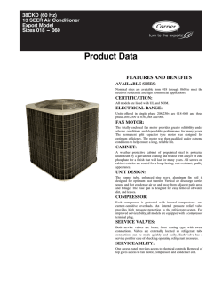
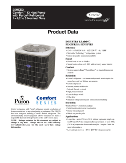
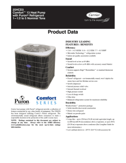
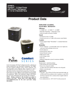

© Copyright 2026