
Canadian Licensed Pharmacy - LTD. Chemistry Behind Viagra
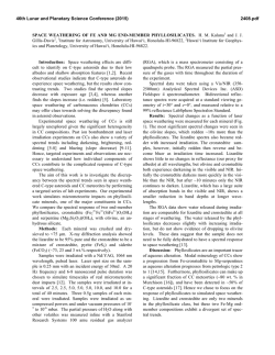
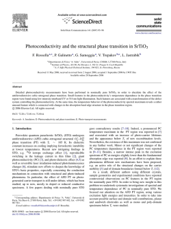
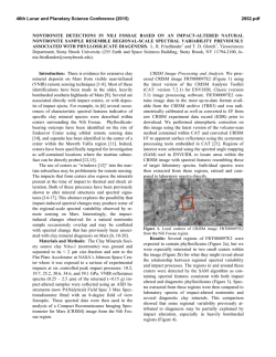
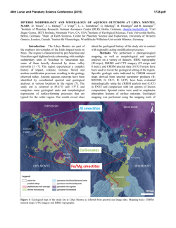
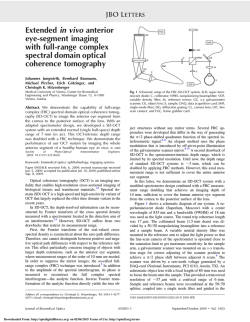
Copyright (c) 1997 Institute of Electrical and Electronics Engineers. Reprinted, with permission, from
MILCOM 1997.
This material is posted here with permission of the IEEE. Internal or personal use of this material is permitted.
However, permission to reprint/republish this material for advertising or promotional purposes or for creating
new collective works for resale or redistribution must be obtained from the IEEE by sending a blank email
message to [email protected].
By choosing to view this document, you agree to all provisions of the copyright laws protecting it.
HIGH DATA RATE UHF SATCOM
Donald R. Stephens, Member, IEEE
Kevin C. Kreitzer, Member, IEEE
Raytheon E-Systems
St. Petersburg, Florida
though the uplink signal may be spectrally contained, the
hard limiters in the UHF SATCOM satellite cause a
regeneration of the previously filtered spectrum. The
result is significant out-of-band spectral energy.
ABSTRACT
Users of UHF SATCOM require higher data rates to
support today’s sophisticated C4I mission planning and
execution methods that are associated with the Digital
Battlefield of the war fighter. Unfortunately, the UHF
SATCOM channel has characteristics which prevent the
implementation of advanced modulation techniques
developed in the commercial industry. As an example, the
QAM modulation format of cable modems cannot be
transmitted through the limiters in the UHF satellites
because it does not have a constant waveform envelope.
For optimum UHF satellite transponder performance, the
modulation must have a constant envelope. This paper
discusses modulation formats that have a constant
envelope and a Bits/Hertz performance much closer to
Shannon's limit than the current waveforms on UHF
SATCOM. A set of waveforms is presented which is
compatible with the UHF SATCOM specifications and
provides the desired data rate improvement without
requiring additional bandwidth. These waveforms allow a
doubling of the current data rates without requiring
additional bandwidth.
In many applications these
increased data rates are available without increased
transmitter power.
The hard-limiting UHF SATCOM channel also removes
amplitude modulation on the uplink signal. This permits
the use of efficient Class C amplifiers for the uplink
terminals, but eliminates compact modulation waveforms
such as Quadrature Amplitude Modulation (QAM). These
two characteristics of the UHF SATCOM channel,
spectral regrowth and AM suppression, form an implicit
requirement for the modulation waveform -- a constant
envelope.
Consider the degrees of freedom available in designing a
modulation waveform for UHF SATCOM. For a generic
waveform
s (t ) = a(t )e
j φ ( t)
(1)
hard-limiting requires that
a(t ) = constant
(2)
and in order to prevent spectral regrowth
d n φ( t )
dtn
INTRODUCTION
Given the historical use of Binary and Quadrature Phase
Shift Keying (PSK), an obvious method of increasing data
throughput on UHF SATCOM would be increasing the
modulator's alphabet, up to 8 or 16-PSK. However, a
previous government program to increase the data
throughput of UHF SATCOM encountered spectral
regrowth when attempting to filter 16-PSK [1]. Even
(3)
must exist for n≥1.
Figure 1 shows some of the modulation waveforms that
are available for SATCOM. Also shown is the ShannonHartley capacity limit [2],
1
S
C = BRF log 2 ℜℜ 1 + ℜℜ
N ,
THE HIGH DATA RATE UHF SATCOM
WAVEFORM
(4)
Raytheon E-Systems has developed a CPM modulation
scheme as our candidate for the next-generation high data
rate UHF SATCOM waveform. The generalized CPM
waveform is expressed mathematically as
where C is the capacity of the channel, BRF is the channel
bandwidth, S/N is the signal-to-noise ratio. The CPM
spectral efficiency is provided relative to the 5 kHz and
25 kHz UHF SATCOM channels. For example, the
4800 bps CPM waveform fits inside the 5 kHz channel, so
we assign a 0.96 bits/Hz efficiency. The 14400 bps also
fits within the 5 kHz channel, so we assign a 2.88 bits/Hz
spectral efficiency for this waveform. (Recall QPSK
requires 8.2 x bit rate for 99% power within band.)
s (t; α=) =
ϕ (t; α=) = 2π
..
Spectral Efficiency ç
Bits
÷
Hertz
4
16PSK
∞
-∞ i= -∞
h i ai g(τ − iTs )dτ
.
(6)
Ts is the symbol period
TCM 16PSK
TCM 8PSK
2
α= = (,a −2 , a −1 ,a 0 , a1 ,a 2 ) is a specific data sequence
h i {i = 1, 2,, K } is a set of phase modulation indicies which is repeated
8PSK
g}(t) is a frequency pulse - shape function which determines the waveform shaping
High Speed SATCOM
Waveform (CPM) *
For the frequency pulse g(t) in (6), we have selected a
rectangular pulse. In the phase domain, this corresponds
to a linear phase ramp. Referred to as LREC, it is defined
as
QPSK
MSK
FEC QPSK
FEC BPSK
BPSK
1
0 ≤ t ≤ LT
g(t ) = 2 L T
0 otherwise
.
* Bits/Hertz Relative to
Required Channel Bandwidth
0
t
Es is the symbol energy
3
1
(5)
where
5
Shannon's
Capacity Limit
2Es
Cos[2π f 0 t + ϕ (t; α=) + ϕ 0 ]
Ts
10
C
−5
for 10
BER
N
20
30
Figure 1. Spectral Efficiencies of Various Modulations
(7)
Equation (7) indicates that the frequency pulse could
extend over more than one symbol. This is known as
partial response CPM.
Although this deliberate
intersymbol interference can increase signal-to-noise
performance, we selected L=1 which is known as full
response CPM. This means that the phase-change period
is equal to the symbol period. Full response provides
more robust synchronization.
Of all the waveforms shown in Figure 1, only two are
strictly constant envelope. These are Minimum Shift
Keying (MSK) and Continuous Phase Modulation (CPM).
Others such as QPSK, trellis coding of 8-PSK and
16-PSK, all have amplitude variations. Continuous Phase
Modulation (MSK is a special case of CPM) has smooth
phase transitions so that non-linear band-limited channels
are acceptable.
To increase spectral efficiency, we have chosen
quaternary CPM instead of binary CPM. This indicates a
mapping of two data bits per symbol. In other words, the
ai in (6) become
ai = {-3, -1, +1, +3}
(8)
Finally, we have combined modulation and coding by
using a multi-h CPM waveform. This means that the
modulation indices will vary on a symbol-by-symbol
basis. Figure 2 shows an example phase trellis of a
quaternary multi-h, CPM waveform. In the first interval,
the phase will change by either ±4π/16 or ±12π/16,
depending on the input symbol pair. A phase change of
+4π/16 is shown in the example. The next symbol has a
phase change of ±5π/16 or ±15π/16, again depending upon
the input symbol pair. The third transmitted symbol will
2
waveform. The particular trellis codes and frequency
pulses were selected for reasonable levels of modem
complexity. The waveforms can all be implemented in
software for real-time operation with current technology.
again have a phase change of ±4π/16 or ±12π/16, as the
modulation indices are periodic.
H1 = 4š/16
H2 = 5š/16
0
4š/16
+3
8š/16
-3
-3
Waveform
Characteristic
Tradeoff
Comments
CPM
Constant
Envelope
• required for UHF
SATCOM operation
Rectangular
Frequency
Pulse
Far-out
Spectral
Energy
• better close-in
suppression of
sidelobes
• software-only
change to existing
modulators
-1
12š/16
Quaternary
+1
16š/16
Spectral
Containment
-1
• best match with
required data rates
+3
Full Response
20š/16
• reduced processing
costs over 8-ary
+1
Spectral
Containment
• reduced processing
costs over partial
response
• better
synchronization
performance than
partial response
24š/16
Figure 3. Characteristics and Tradeoffs of the High Speed
Waveform.
28š/16
Figures 4 and 5 present the trellis codes used for the
different bit rates on both the 25 kHz and 5 kHz UHF
SATCOM channels. The modulation indices for the
quaternary multi-h CPM waveforms are given, as well as
the C/kT required for 10-5 BER performance. Implicit in
the specifications is a 2 dB receiver implementation loss
and a 2 dB spurious degradation from theoretical. In
Figures 4 and 5 we abbreviate hi = {3π/16, 4π/16} as
h16{3, 4}.
Figure 2.
Quaternary Multi-h CPM Phase Trellis Example
The trellis determines both the spectrum and the Eb/No
performance of the CPM waveform. The spectrum is most
affected by the size of the modulation indices and the
spacing between them. The signal space distance between
the different symbols for CPM is determined by the
integrated phase difference between the two sequences.
The constraint length of a trellis is how many symbols it
takes for two different sequences to end at the same
position in the trellis.
The constraint length and
modulation indices thus both determine the Eb/No
performance of the CPM waveform. By using different
values of h, we can tailor the spectral bandwidth and
signal/noise performance.
There are many different considerations and optimizations
of the CPM waveform [3]. Figure 3 summarizes the
characteristics of the High Data Rate UHF SATCOM
3
Spurious (dBc)
Bit Rate
h16={a,b}
C/kT
5 kHz
10 kHz
14400
{3,4}
52.8
-16.0
-27.7
12000
{4,5}
50.0
-15.0
-30.5
9600
{4,5}
49.0
-18.0
-32.0
8000
{5,6}
47.5
-19.2
-34.0
7200
{6,7}
47.2
-21.0
-28.0
6000
{7,10}
46.0
-16.0
-32.0
4800
{12,13}
44.0
-18.9
-30.4
Figure 4. 5 kHz Waveform Specifications
Figure 7. Measured Spectrum for 64 kbits/s,
hi = {4π/16, 5π/16}
Spurious (dBc)
Bit Rate
h16={a,b}
C/kT
25 kHz
100 kHz
76800
{3,4}
60.1
-13.9
-41.6
64000
{4,5}
57.5
-14.0
-39.0
56000
{4,5}
57.0
-15.5
-43.0
48000
{4,5}
56.0
-18.0
-43.0
40000
{5,6}
55.0
-22.3
-47.0
32000
{6,7}
53.2
-25.0
-47.0
19200
{12,13}
50.0
-22.3
-47.3
The significance of CPM on UHF SATCOM is shown in
Figure 8, where the projected CPM performance is
contrasted with the current UHF waveforms. The link
power is referenced to 9600 bits/s operation. As shown,
with exactly the same carrier power, antenna, etc., the
CPM waveform can support double the data rate. Other
higher data rates can be provided without large increases
in C/kT. Further, significant link margin improvements
can be acheived by using CPM in place of PSK at the
existing data rates -- e.g., 5 dB improvement at
19200 bits/s.
4
Figure 5. 25 kHz Waveform Specifications
2
0
Shown in Figure 6 is the analytic spectrum for a
quaternary multi-h CPM waveform with modulation
indices of hi = {4π/16, 5π/16}. The horizontal axis is
normalized to symbol rates. For reference, an unfiltered
QPSK spectrum is also shown. Figure 7 is a measured
spectrum for the 64 kbits/s rate with modulation indices of
hi = {4π/16, 5π/16}.
-2
-4
-6
-8
-10
9600
PSK
-2
-1
1
2
3
32000
40000
48000
56000
64000
76800
Bit Rate (Bits/Sec)
IMPLEMENTATION
1
Ts
Raytheon E-Systems has implemented the CPM
waveforms as part of the Multiple Output SATCOM
Transceiver (MOST). The MOST is a software-based
radio using six processors. Three of these processors
perform baseband I/O functions, one performs network
and transport layer functions, one performs link layer
functions, and one performs modulation and demodulation
functions. The processor performing modulation and
demodulation is referred to as the Modem Processor. A
Modem Processor transmit block diagram is shown in
Figure 9 and a receive block diagram is shown in Figure
10.
-1 0
QP S K
-2 0
-3 0
CPM
19200
Figure 8. Comparison of CPM and Existing UHF
Waveforms
dB
10
-3
CPM
-4 0
Figure 6. Analytic Spectrum for hi = {4π/16, 5π/16}
4
preamble
tables
timer
input
routine
mapping
routine
For non-coded modulations, the MLE matched filter
correlates the incoming waveform against all possible
incoming waveforms. It uses the correlation scores to
decide which waveform was most likely received. For
coded modulation schemes such as CPM, this is not
sufficient since it does not take advantage of the inherent
memory in the waveform. Instead, the correlation scores
serve as path metrics for a Viterbi Decoder [4]. The
output of the Viterbi Decoder also serves as the data
decision algorithm.
DDS
Figure 9. MOST Modulator Block Diagram
The Phase Detectors are constructed by taking the partial
derivatives of the best survivor from the Viterbi Algorithm
with respect to phase and time [5].
Modulation of the CPM waveform in the MOST
architecture reduces to a simple table look-up. Because
the waveform uses full response rectangular frequency
pulse shaping, modulation requires generation of eight
frequency steps corresponding to ±h1, ±3h1, ±h2, and
±3h2. The MOST Radio generates these frequency steps
using Direct Digital Synthesis (DDS). Modulation, then,
is simply a task of mapping the incoming symbol to the
appropriate frequency control word for the DDS and
sending it to the control latch at the proper time.
Carrier
Loop
Filter
Carrier
NCO
SUMMARY
A set of waveforms is presented which is compatible with
the UHF SATCOM specifications and provides desired
data rate improvement without requiring additional
bandwidth. Known as quaternary full response multi-h
CPM, these waveforms allow a doubling of the current
data rates without requiring additional bandwidth. In
many applications these increased data rates are available
without increased transmitter power. The waveforms are
constant envelope to accommodate the hard-limiting UHF
SATCOM channel. Finally, these waveforms have been
successfully implemented in the Raytheon E-Systems
MOST Radio.
Carrier
Phase
Detector
Lock
Detector
A/D
Converter
Data
Detection
MLE
Timer
Clock
NCO
Clock
Loop
Filter
Clock
Phase
Detector
Figure 10. MOST Demodulator Block Diagram
Demodulating the CPM waveform, like all MOST
demodulation waveforms, utilizes a Maximum Likelihood
Estimation (MLE) architecture. MLE demodulation of
CPM closely resembles traditional phase-locked loop
demodulation with three notable exceptions -- the phase
detector, the matched filter, and the data decision
algorithm.
5
[1]
QUALCOMM "High Data Rate Satellite
Communications Study Final Technical Report,"
Prepared for Naval Oceans Systems Center, Sept.
30, 1992.
[2]
Shannon, C. E., “Communication in the Presence
of Noise,” Proc. IRE, pp. 10-21, Jan. 1949.
[3]
Anderson, J.B., Aulin, T., C.E. W. Sundberg,
Digital Phase Modulation, Plenum Press, New
York, NY, 1986.
[4]
Forney, G. D., “The Viterbi Algorithm,” Proc.
IEEE, vol. 61, pp. 268-277, Mar. 1973.
[5]
Premji, A. and Taylor, D. P., “A Practical
Receiver Structure for Multi-h CPM Signals,”
IEEE Trans. Commun., vol. COM-35, pp. 901908, Sept, 1987.
© Copyright 2026