
Manual - Motos Serpento
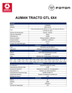
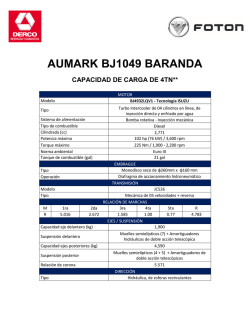
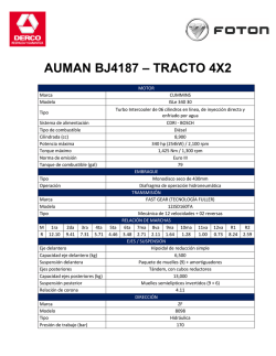
M a n u a l de Usuario
MOTOCICLETA MODELO:
COYOTE 250
MANUAL DE USUARIO Y MANTENIMIENTO
PARA LA MOTOCICLETA
MANUAL DEL USUARIO
• COYOTE 250
Prefacio
Muchas gracias por adquirir esta motocicleta.
Este manual cubre las especificaciones principales, estructura básica, y principales procedimientos de operación, mantenimiento y detección y
solución de problemas. Le ayudará a familiarizarse con todos los elementos necesarios para que usted pueda utilizar su vehículo con diversión
y placer, y sin dificultad, durante una larga vida útil.
Los productos siempre están sujetos a mejoras continuas, por lo cual habrá algunas diferencias entre el vehículo y el manual, sin notificación
previa.
CONTENIDO
I. Maneje con cuidado II. DATOS PRINCIPALES
III. PARTES & COMPONENTES
IV. OPERACION
Interruptor de arranque
Manija de la válvula de combustible
Encender el motor Interruptores en el puño derecho
Cambio de marchas
V. Revisiones, ajustes y mantenimiento Revisión del aceite del motor Cambio de aceite del motor Limpieza del tanque de aceite del motor Revisión de la bujía
Revisión y limpieza del filtro de aire Ajuste del cable del acelerador
Ajuste del carburador Revisión y ajuste de la tapa de la válvula de aire Ajuste del embrague
Revisión de frenos
Ajuste del freno frontal
5
7
8
12
12
12
13
14
16
17
17
17
18
18
19
20
20
21
22
22
23
Ajuste del freno trasero
Ajuste de la Cadena
Ajuste del interruptor de la luz de freno
Revisión de la batería
Reemplazo del fusible
Lavado del vehículo
Mantenimiento fuera de uso
Retomar el uso
Diagrama de rutina de mantenimiento
VI. DIAGRAMA ELÉCTRICO
24
25
26
26
27
27
28
29
30
33
MANUAL DEL USUARIO
• COYOTE 250
I. Maneje con cuidado
Reglas para manejar con cuidado
Se debe revisar el vehículo antes de encender el motor, para prevenir contratiempos y daños a los componentes.
Este vehículo debe ser conducido únicamente por personas calificadas, que hayan aprobado la prueba de manejo y tengan una licencia de
conducir. Ninguna persona sin licencia debe manejar este vehículo.
Manejar requiere de total atención por parte del conductor. Ponga atención a los siguientes elementos para evitar accidentes con otros
vehículos motorizados:
• No maneje muy cerca de otros vehículos.
• Nunca compita por un carril.
• Cumpla estrictamente con las reglas de tránsito locales.
• Ya que el exceso de velocidad es la causa de muchos accidentes, no maneje a una velocidad que la situación actual no le permita control
sobre el vehículo.
• Active las luces direccionales cuando vaya a doblar o cambiar de carril.
• Ponga cuidado especial en los cruces, entradas y salidas de estacionamientos o en el carril para automóviles.
• Mientras va manejando, tome el puño izquierdo con la mano izquierda y el puño del acelerador con la mano derecha, colocando los pies en
los reposapiés.
• El maletero está diseñado para cargar objetos ligeros que deben asegurarse para prevenir contratiempos durante la conducción.
5
Equipo de protección
1. El equipo de protección debe ser utilizado durante la conducción del vehículo para la seguridad personal del conductor y comprende de un
casco con máscara protectora, lentes de protección contra el polvo y guantes.
2. El pasajero deberá usar botas altas o ropa larga para proteger sus piernas contra el silenciador de escape que se calienta durante el viaje.
3. La ropa floja no es apta para viajar en motocicleta ya que puede atorarse en la palanca de mando, pedal de arranque, reposapiés o llanta,
y causar peligro.
Modificación del vehículo
Precaución:
Cualquier modificación no autorizada al vehículo o reemplazo de partes originales no garantiza el uso seguro del vehículo y es ilícito. El usuario
debe cumplir con las regulaciones de las autoridades de tránsito. No nos hacemos responsables por ninguna modificación no autorizada al
vehículo.
Carga de objetos
Precaución:
El diseño de la motocicleta requiere distribución de los objetos de carga para mantener el equilibro. La mala distribución del peso puede
afectar de manera negativa el desempeño y estabilidad del vehículo. El fabricante no será responsable debido a las razones mencionadas
anteriormente.
6
MANUAL DEL USUARIO
• COYOTE 250
II. DATOS PRINCIPALES
Largo total
2240mm
Diámetro y carrera del cilindro
69.0×62.2
Ancho total
860mm
Índice de compresión
9.0:1
Altura total
1140mm
Salida, máxima
12.0Kw/7500R/min
Distancia entre ejes
1505mm
Torque máximo
18.0N.m/6000r/min
Peso seco
170kg
Ralentí
1500±150r/min
Carga máxima
150kg
Cilindrada
232.6ml
Llanta delantera
90/90-18/225
Bujía
D8REA
Llanta trasera
130/90-15/225
Espacio de la bujía
0.6mm-0.7mm
Velocidad máxima
≥105km/h
Distancia de frenado
≤7m
Capacidad de ascensión
≥36º
Tapa de válvula de aire
Distancia al suelo
Válvula de escape:0.03~0.05mm
Válvula de admisión: 0.04~0.07mm
135mm
DATOS PRINCIPALES
Volumen de aceite lubricante
1.1L
Fusible
15A
Capacidad del tanque de gasolina
16L
Batería
12V/4Ah
Relación de transmisión
Luz delantera
12V-35W/35W
1er cambio
2.909
Luz de freno
12V-5W/21W
2ndo cambio
1.867
Betraying light
3er cambio
1.375
Luz de señalización
12V-10W×4
4to cambio
1.150
Indicador de señalización
12V-1.7W×2
5to cambio
0.954
Luz del medidor
12V-3W×2
Relación de transmisión del piñón
2.800
Indicador de luces altas
12V-1.7W
Relación de transmisión primaria
3.333
Medios de arranque
12V-5W
C.D.I
7
III. PARTES & COMPONENTES
Espejo retrovisor izquierdo
Medidor
Ignición y bloqueo del manubrio
Puño izquierdo
Interruptor de la bocina
8
Espejo retrovisor derecho
Puño del acelerador
Seguro del tanque de combustible
Interruptor de arranque del motor
MANUAL DEL USUARIO
No.
Nombre
Descripción
Velocímetro
En km/h
• COYOTE 250
El indicador izquierdo se enciende
cuando
Señal de cambio
la
señal
de
cambio
apunta a la izquierda; el derecho
se enciende cuando la señal de
cambio apunta a la derecha.
Indicador de luces altas
Posición de las marchas
Indicador neutral
Tacómetro.
Medidor de viaje
Se enciende cuando está en
posición neutral.
La posición de las marchas se
muestra
Se enciende en la posición neutral.
Muestra la velocidad (rpm) del
motor
Muestra la distancia del viaje
9
Número de serie del chasis [Número de chasis.(VIN)]
Está ubicado al lado derecho y la marca está en el frente.
Luz de señal de cambio frontal
Luz de señal de cambio trasera
Amortiguador frontal
Llanta delantera
Llanta trasera
Soporte principal
10
MANUAL DEL USUARIO
• COYOTE 250
Cojín del asiento
Silenciador de escape
11
IV. OPERACION
Interruptor de arranque
Interruptor de arranque
Posición
Función
Comentarios
Para detener el vehículo (apagando
todos los circuitos )
La llave puede ser
sacada
Para encender o conducir el
vehículo (utilizando todos los
circuitos principales )
La llave no puede ser
sacada
1. Llenar el tanque de combustible
La capacidad del tanque de combustible es de 18 L en total, incluyendo 1.1L de reserva. Esta motocicleta utiliza gasolina baja en plomo o sin
plomo No. 93 o superior. Para llenar el vehículo de combustible, abra la tapa de seguridad y llene a través del agujero, luego cierre la tapa del
tanque.
2. Operación de la válvula de combustible (la válvula del tanque de combustible)
ON: Cuando la manija de la válvula de combustible está en posición “ON”, el circuito de combustible es para el suministro de combustible.
OFF: Cuando la manija de la válvula de combustible está en posición “OFF”, el circuito de combustible está interrumpido y sin suministro.
RES: Cuando la manija de la válvula de combustible está en posición “RES”, el combustible se suministra desde el tanque de reserva.
Manija de la válvula de combustible (ON\OFF\RES)
Manija de la válvula de (Nota: El combustible de reserva solamente puede ser utilizado cuando el suministro normal se ha acabado). En este caso, se debe llenar el
combustible
tanque lo antes posible, ya que solamente queda 1.1L de combustible de reserva.
12
MANUAL DEL USUARIO
• COYOTE 250
Encender el motor
Mueva la llave en el interruptor de arranque a la posición de “ON”.
Ponga el interruptor de emergencia en posición “ ”.
Asegúrese de estar en posición neutral, que es donde debería estar.
Asegúrese de la cantidad de combustible en el tanque.
Ponga la manija de la válvula de combustible en la posición “ON”
Para encender un motor frío:
Saque la palanca del estrangulador (para cerrar el estrangulador)
Rote el puño del acelerador entre 1/8 y ¼.
Encienda el motor con el sistema eléctrico o con el pedal.
Gire sutilmente el puño del acelerador para incrementar la velocidad del motor para calentar el motor.
Gire la palanca del estrangulador del carburador hacia la “B”, y únicamente abra la totalidad del estrangulador cuando el motor esté
suficientemente caliente.
Precaución:
El motor solo puede encenderse después de que la posición neutral haya sido asegurada, de lo contrario, podría ocurrir un accidente.
El ralentí innecesario (especialmente a velocidades altas) es dañino para el motor.
Procedimiento para detener el motor:
Suelte el puño del acelerador para reducir la velocidad del motor.
Gire a la posición neutral.
Ponga la llave en el interruptor de arranque y muévalo en la posición de “OFF”.
Ponga la manija de la válvula de combustible (la válvula del tanque de combustible) en la posición de “OFF”.
13
Interruptores en el puño derecho
1) Interruptor de la luz delantera.
El interruptor de la luz delantera tiene 3 posiciones “
”, “
”y“
” (un punto blanco)
“
”: cuando el interruptor está en esta posición, la luz de freno, luz delantera y del medidor están todas encendidas.
“
”: cuando el interruptor está en esta posición, la luz de freno, luz de betraying y luz del medidor están todas encendidas.
“
”: cuando está en esta posición, la luz delantera, la luz de freno, la luz de betraying y la luz del medidor están todas apagadas.
La luz delantera y luz de freno se encenderán únicamente cuando el vehículo esté encendido.
2) Encendedor eléctrico (este dispositivo no existe en los vehículos que solamente se encienden con un pedal)
El botón eléctrico está ubicado debajo del interruptor de la luz delantera. El motor se encenderá al presionar este botón.
3) Interruptor de emergencia
Cuando encienda el motor ponga el interruptor de emergencia en posición “ ” posición para detener el motor directamente al cortar la
corriente eléctrica.
Interruptor de emergencia
Puño acelerador
Interruptor de iluminación frontal
Botón de encendido
14
MANUAL DEL USUARIO
• COYOTE 250
Interruptores del puño izquierdo
1) Interruptor de cambio de luces
Posición, Luz delantera está alta.
Posición, Luz delantera está baja.
2) Interruptor de señal de cambio
Posición, izquierda
Posición, derecha
3) Botón de la bocina
Presione esté botón para tocar la bocina.
Interruptor de cambio de luces
Interruptor de señal de cambio
Bocina
15
Cambio de marchas
Caliente el motor para funcionamiento normal.
Cuando el motor está ocioso, suelte el embrague y pise el pedal de cambio de marchas a la marcha de la primera posición.
Gradualmente incremente la velocidad del motor y suelte el embrague suavemente, con buena coordinación entre ambos movimientos
para asegurar una conducción natural.
Cuando la motocicleta alcance un estado balanceado de funcionamiento, suelte de nuevo el embrague y pise el pedal de cambio de
marchas a la marcha de la segunda posición. La marcha puede ser cambiada a las siguientes posiciones de la misma manera.
Cambiar de marchas hacia adelante
5
4
3
2
N
1
Cambiar de marchas hacia atrás
16
MANUAL DEL USUARIO
• COYOTE 250
V. Revisiones, ajustes y mantenimiento
Revisión del aceite del motor
Debe revisar el aceite del vehículo colocándolo sobre el soporte principal en un terreno plano. El nivel del aceite debería estar entre las líneas
superiores e inferiores del medidor de aceite, que no está atornillado al orificio de llenado.
Se recomienda el uso de un aceite de alta calidad para un motor de cuatro tiempos, Clase SE o SD en la clasificación API, y con una viscosidad
SAE de 15W-40QE, para que el vehículo tenga una larga vida útil.
En caso de que estos aceites no estén disponibles, se debe escoger un sustituto adecuado para la temperatura ambiente de aplicación, de
acuerdo con la siguiente tabla.
Medidor de aceite del motor
Cambio de aceite del motor
El aceite del motor juega un papel muy importante en la operación normal del motor y, por esta razón, es necesario revisar el aceite del motor
de la motocicleta cada 800-1000 km como se indica a continuación:
Quite el tapón cárter de la base del motor caliente para drenar el aceite viejo.
Limpie la rejilla del filtro del aceite y vuelva a colocarla. Luego llene con 0.9L de aceite para motor nuevo y encienda el motor por 2-3 minutos.
Detenga el motor por 2-3 minutos y revise si el nivel de aceite está entre las líneas superiores e inferiores del medidor de aceite.
No utilice ningún aceite para motor de un grado distinto al especificado para evitar daños al motor.
17
Limpieza del tanque de aceite del motor
Drene todo el aceite fuera del tanque de aceite del motor.
Desmonte las partes relacionadas.
Limpie todas las partes relacionadas.
Llene con el aceite requerido.
*Este trabajo no debe ser realizado por personas que no tenga el entrenamiento necesario; debe realizarse en un centro de servicio autorizado.
Tapón cárter para drenado de aceite del motor
Revisión de la bujía
Quite la tapa de la bujía y desatorníllela con la llave para bujías.
Limpie la bujía por todos sus lados o reemplácela si está corroída o sucia.
Regule el espacio de la bujía a 0.65-0.75mm.
Se debe utilizar el tipo de bujía especificado aquí: D8REA
18
0. 65-0. 75
MANUAL DEL USUARIO
• COYOTE 250
Revisión y limpieza del filtro de aire
Saque el filtro de aire y revise si está o no contaminado.
Desmontaje:
Quite el tornillo de la cubierta izquierda del filtro, abra la cubierta izquierda y desarme el filtro de aire.
Limpieza:
Limpie el filtro con aceite de limpieza y séquelo con una toalla seca.
Remoje el filtro en aceite de motor limpio. Exprímalo para secarlo y colóquelo de nuevo en la posición correcta.
Aceite recomendado: 15W/40QE
Precaución:
El filtro de aire debe estar intacto o el motor se atascará con polvo y tierra, lo cual resultará en una vida útil más corta.
Cuando lave el vehículo, evite que entre agua al filtro.
El filtro nunca debe limpiarse con gasolina o cualquier otro agente inflamable.
Filtro de aire
Abrazadera manillar
19
Ajuste del cable del acelerador
Asegúrese de que la tuerca de ajuste del cable del acelerador funcione con normalidad.
Revise que el puño del acelerador pueda girarse de manera libre y adecuada.
El movimiento requerido para girar de manera adecuada debe ser de: 2-6mm.
Si el puño del acelerador no se puede mover con libertad, gire la tuerca para ajustarlo.
*Después del ajuste, encienda el motor y revise el movimiento de nuevo. Repita el ajuste si fuese necesario.
Tuerca de ajuste
Tuerca de bloqueo
Ajuste del carburador
Precaución:
El ajuste del ralentí del motor se debe hacer con el motor caliente.
Ajuste el ralentí del motor al valor requerido ajustando el tornillo con el vehículo puesto sobre una
superficie plana.
Ralentí requerido: 1500r/min.
Tornillo para ajustar el ralentí
20
MANUAL DEL USUARIO
• COYOTE 250
Revisión y ajuste de la tapa de la válvula de aire
Si la válvula de aire tiene un espacio muy grande, saldrá ruido. Sin embargo, si el espacio es muy pequeño o no tiene espacio, el cierre de
la válvula se dificultará, lo cual causará que la válvula se queme y la salida baje. Por lo tanto, el espacio de la válvula de aire debe revisarse
periódicamente.
El espacio de la válvula de aire debe ser inspeccionada y ajustada con el motor frío y siguiendo el siguiente procedimiento:
1) Quite la capa del hoyo central y del hoyo de la parte superior (el hoyo de observación del tiempo de ignición) en la cobertura izquierda del
cárter.
2) Quite la tapa de las dos válvulas de aire de la cabeza del cilindro.
3) Inserte la llave “T” en el hoyo central de la cobertura del cárter, empújela contra la tuerca del volante del motor y luego gire el volante del
motor en el sentido de las manecillas del reloj hasta que la “T” del volante del motor se alinee con la línea en la parte superior de la cobertura
del cárter. Gire el balancín sutilmente. Un balancín suelto (que indica la existencia de espacio libre) muestra que el pistón está en la posición
más baja del tiempo de compresión. En este caso, gire continuamente la llave “T” en el sentido de las manecillas del reloj 360 grados hasta
que se alinee con las marcas, donde la válvula puede ser ajustada. Luego, revise el espacio de la válvula insertando una antena entre el tornillo
de ajuste la válvula y el final de la válvula.
El espacio de la válvula de aire debe ser de 0.03-0.07mm para la válvula de admisión y de escape, respectivamente.
4) Si necesita hacer un ajuste, suelte la tuerca de bloqueo de la válvula, gire la tuerca de ajuste
hasta que sienta una resistencia sutil cuando inserte la antena.
5) Al finalizar el ajuste, refuerce el “bloqueo” para prevenir que se suelte y revise de nuevo
para asegurarse que el espacio de la válvula sea correcto antes de volver a colocar
las tapas desmontadas en el hoyo central.
Tapa de la válvula
Tapa del hoyo central
21
Ajuste del embrague
El embrague debería ser ajustado con el motor apagado.
Debería tener holgura de 10-20 mm al final del pedal del embrague como se muestra en la imagen a la izquierda.
Cuando se requieran ajustes, suelte el ajuste del pedal del embrague a la holgura requerida. En caso de que se necesite ajustar mucho, mueva
el tornillo de ajuste del embrague hacia la derecha del cárter.
Encienda el motor para asegurarse de que el embrague haya sido ajustado correctamente.
El reajuste debe hacerse si el embrague se está deslizando o los cambios de marchas se han vuelto difíciles.
Revisión de frenos
1) Levante los frenos del frente y de atrás respectivamente y revise el degaste de las zapatas. Si la marca “.” en la cobertura del tambor del
freno se alinea con la marca “.” en el cam del freno, esto significa que las zapatas están desgastadas al límite y deben ser reemplazadas.
2) El reemplazo debe llevarse a cabo en un centro de servicio designado y se recomienda utilizar repuestos fabricados por nuestra compañía
de 10-20 mm.
22
MANUAL DEL USUARIO
• COYOTE 250
Ajuste del freno frontal
(1) El pedal del freno frontal tiene una holgura de 10-20 mm como se muestra en la figura a la derecha.
(2) Si necesita hacer ajustes, gire la tuerca de ajuste cerca del lado más bajo del cubo frontal, con dirección a las manecillas del reloj para
reducir la holgura, y en dirección contraria para aumentar la holgura de la palanca del freno.
(3) Después de realizar el ajuste, la muesca de la tuerca de ajuste debería estar alineada con el vástago del brazo del freno.
Precaución:
Después del ajuste, revise el sistema de frenos frontal. La luz de freno debe encenderse cuando se aprieta la palanca de freno.
Manguera de aceite para discos de freno
Plato de discos de freno
Bomba de disco de freno
23
Ajuste del freno trasero
El vehículo debe ponerse sobre el soporte principal para esta revisión.
(1) El pedal del freno trasero tiene una holgura de 20-30mm como se muestra en la figura de la derecha.
(2) Para hacer ajustes, mueva la tuerca de ajuste del freno trasero en dirección a las manecillas del reloj para reducir la holgura y en dirección
contraria para aumentar la holgura del pedal de freno.
(3) Después del ajuste, la muesca de la tuerca de ajuste debe estar alineada con el vástago del freno del brazo.
Precaución:
Después de la regulación, revise el sistema de frenado trasero. La luz de freno debería encenderse a tiempo cuando se presiona el
pedal de freno.
Palanca de freno
Pedal del freno trasero
Leva del Freno
Brazo del freno
20-30mm
24
Tuerca de ajuste
Vástago del brazo del freno
MANUAL DEL USUARIO
• COYOTE 250
Ajuste de la Cadena
Revise el desgaste, tensión y lubricación de la cadena.
(1) Ponga la motocicleta sobre el soporte principal, gire las partes superiores e inferiores de la cadena a mano para revisar la tensión y revisar
si la tensión está dentro del rango de 10-22mm necesario.
(2) Cuando necesite ajustar la cadena, suelta la tuerca del eje y la tuerca de bloqueo de la llanta trasera, luego tense la cadena en la tensión
necesaria girando la tuerca de ajuste.
(3)Aplique un poco de grasa a la cadena.
Precaución:
Al finalizar el ajuste, las marcas en el ajustador de la cadena deberían estar en coordinación con la línea grabada en la horquilla horizontal.
Ajustador de cadena (con graduaciones)
Interruptor de luz de freno
Tuerca de ajuste
Eje soporte
Tuerca del eje de la llanta trasera
Resorte del interruptor de la luz de freno
25
Ajuste del interruptor de la luz de freno
La luz de freno debería encenderse de inmediato cuando la llanta trasera se frena. Si esto no ocurre, se debe ajustar girando la tuerca de
ajuste.
Con el interruptor de la luz de ajuste en posición “ON”, la luz de freno debería encenderse. Si esto no ocurre, debe revisar si la lámpara de
freno, el circuito o el interruptor están funcionando bien, reemplace en caso de que estén en mal estado.
Precaución:
Para ajustar el interruptor de las luces de freno, el freno necesita revisarse para asegurarse de que tenga holgura de movimiento dentro del
rango especificado.
Revisión de la batería
Abra la cubierta derecha.
Limpie el polvo y la corrosión de la superficie de la batería.
Ponga el vehículo en posición vertical para revisar si el nivel de los electrolitos de la batería está entre las marcas superiores e inferiores.
Conector
Conector
Si está por debajo de las marcas inferiores, se debe agregar agua destilada a la batería.
Los conectores conductivos de la batería que estén corroídos deben ser reemplazados.
Precaución:
Para desarmar la batería, desconecte el electrodo negativo (-) antes de desconectar el positivo (+), y viceversa durante la instalación.
Asegure cualquier contacto entre el electrodo positivo (+) con el cuerpo del vehículo.
Nunca sobrepase el nivel de electrolitos por encima de la marca superior al agregar agua. De lo contrario, habrá corrosión.
El electrolito contiene ácido sulfúrico y causará serias lesiones a los ojos y la piel si entra en contacto. En caso de contacto, lave durante 5
Marca inferior de
minutos y vea a un doctor de inmediato.
nivel de electrolitos
No permita que entren sustancias en la batería durante el desmontaje e instalación.
Marca superior de La manguera de aire debe mantenerse sin obstrucciones.
Negativo (-)
Positivo (+)
nivel de electrolitos
26
MANUAL DEL USUARIO
• COYOTE 250
Reemplazo del fusible
Ponga el interruptor de ignición en “OFF”. Se debe reemplazar el fusible con el tubo de fusible 15A.
Abra la cubierta izquierda, quite la pieza que sostiene el fusible al costado de la batería y reemplace el tubo del fusible.
Si se quiebra el tubo del fusible de nuevo al momento de instalarlo, esto significa que hay un problema con otras partes eléctricas.
Precaución:
No utilice ningún fusible por encima de 15A.
Asegúrese de no mojar la batería cuando lava el vehículo.
Lavado del vehículo
Lave el vehículo de manera regular para preservar el color de la carrocería y facilitar la revisión de daños y cualquier fuga de aceite.
Precaución:
Lavar la motocicleta con agua a presión puede causar daños a algunos de sus componentes. Por lo tanto, no lave con agua a presión las
siguientes partes:
• Cubo de rueda
• Mufla
• Tanque de combustible y porción inferior del cojín
• Carburador
• Interruptor de ignición y bloque del manubrio
• Medidores
(1) Después de sacudir el vehículo, lávelo con agua limpia para remover la suciedad y prevenir la corrosión. Los componentes plásticos deben
lavarse con una toalla o esponja y detergente neutral, seguido de un enjuague con agua limpia.
(2) Después de que el vehículo lavado se haya secado al aire, engrase la cadena y encienda el motor por unos minutos.
(3) Antes de manejar, revise con cuidado el sistema de frenos con cuidado y haga los ajustes si fuera necesario.
27
Mantenimiento fuera de uso
Almacenamiento y mantenimiento
Si necesita almacenar la motocicleta por un periodo largo de tiempo, preste atención a la exposición de humedad, luz del sol, y lluvia para
protegerla de daños innecesarios. Realice los siguientes procedimientos cuando antes de almacenar el vehículo:
Cambie el aceite lubricante.
Engrase la cadena.
Drene el combustible del tanque de combustible y del carburador (si el vehículo no se va a utilizar por más de un mes, debe drenar la
totalidad del combustible totalmente), apague la válvula de combustible y llene el tanque de combustible con solución anti-herrumbre, y cierre
el tanque.
Precaución:
Ya que el combustible es inflamable, el motor debe estar apagado antes de llenar o drenar el tanque, y se prohíbe fumar en el lugar donde se
almacene, llene o drene combustible.
Saque la bujía, llene el cilindro con 15-20 ml de aceite lubricante limpio, presione el pedal de arranque varias veces y finalmente instale la
bujía de nuevo.
Atención:
El interruptor de ignición debe estar el “OFF” antes de presionar el pedal de arranque. Para proteger el sistema de ignición de daño, la bujía
debe estar colocada en su tapa y conectada a tierra.
Desarme la batería en un lugar con sombra, fresco y buena ventilación. Se sugiere que la batería se cambie una vez al mes.
Limpie el vehículo, rocíe las partes de color con un agente de fijación de color y aplique aceite anti-herrumbre a las partes vulnerables al
herrumbre.
Infle las llantas según el requerimiento con el vehículo levantado del suelo.
Ponga la cubierta sobre la motocicleta.
28
MANUAL DEL USUARIO
• COYOTE 250
Retomar el uso
Quite la cubierta y limpie el vehículo. Cambie el aceite lubricante si el vehículo ha estado fuera de servicio por más de 4 meses.
Cambie la batería y vuelva a montarla.
Drene la solución anti-herrumbre del tanque de combustible, luego llénelo con combustible al nivel requerido.
Antes de manejar, revise que el vehículo esté funcionando bien manejando a baja velocidad en un lugar seguro.
Diagrama de rutina de mantenimiento
Debe darle un buen mantenimiento a su vehículo según se especifica en la siguiente tabla, donde:
“I” significa: Revise, limpie, ajuste, lubrique y/o reemplace según sea necesario.
“C” significa: Limpieza necesaria.
“R” significa: Reemplazo necesario.
“A” significa: Ajuste necesario.
“L” significa: Lubricación necesaria.
“ ” significa: Este tipo de mantenimiento debe realizarse en un centro de servicio. También puede realizarse por el usuario, siempre y cuando
utilice este manual para referencia y tenga las herramientas especiales necesarias y capacidad para hacer el trabajo.
“
” significa: Este tipo de mantenimiento debe ser realizado únicamente por el personal de un centro de General Accessories Corp. para
que sea seguro.
Notas:
1. El mantenimiento debe realizarse con más frecuencia cuando la motocicleta ande por lugares polvosos.
2. Cuando la lectura del odómetro exceda las figuras máximas especificadas en esta tabla, el mantenimiento se debe realizar en ciclos de
acuerdo con los intervalos de millas especificados aquí.
29
Diagrama de rutina de mantenimiento
Frecuencia
Ítem /frecuencia
Ítem
de
400 0km
8000km
12000km
I
I
I
*
Circuito
de
combustible
*
Filtro de combustible
C
C
C
C
*
Sistema operativo de aceleración
I
I
I
I
*
Estrangulador del carburador
I
I
I
*
Sistema
Odómetro km(Nota 2)
1000km
Elemento del filtro de aire
R-anualmente
I
C
C
C
Bujía
R-anualmente
R
I
I
I
Espacio de válvula de aire
I
I
I
I
Espacio de válvula de aire
R
I
I
Aceite lubricante para motor
Un reemplazo cada 2000km
Rejilla para el aceite lubricante
C
C
*
Tensión de la cadena
A
A
A
*
Velocidad ociosa del carburador
I
I
Mensualmente
I
Cadena
A
Batería
I、L cada 500km
I
Zapatas
R-2años
Sistema de frenado trasero
el
líquido
I
de
I
I
I
I
I
I
I
I
I
I
I
I
I
I
**
Manguera
frenos
**
Taza para el líquido de frenos
**
Líquido de frenos
**
Sistema de frenado frontal
I
I
I
I
*
Interruptor de freno trasero
I
I
I
I
*
Cambio de luces de luz delantera
I
I
I
I
Embrague
I
I
I
I
I
I
I
Un reemplazo cada dos años
Soporte lateral
30
C
R-4años
para
Comentario
I
I
I
*
Suspensión
I
I
I
I
*
Tuercas, tornillos y otros.
I
I
I
I
**
Llantas/Radios
I
I
I
I
**
Soporte del manubrio
I
I
También para
estilos
de
disco.
MANUAL DEL USUARIO
• COYOTE 250
Funciones, operación e instrucciones para el control remoto
Funciones:
Antirrobo acústico-óptico:
Presione el botón. La bocina sonará y la luz de cambio se encenderá una vez. Tres segundos después, el sistema de antirrobo acústico-óptico
estará activo.
Sensor antirrobo:
En estado antirrobo, cualquier golpe a la motocicleta hará que la bocina suene una vez y la luz se encienda una vez. En caso de que hayan
otros movimientos que causen molestias a la motocicleta, después de tres segundos se encenderá la alarma de inmediato: sonará la bocina,
las luces se encenderán y apagarán y el motor se bloqueará de inmediato. La motocicleta permanecerá en estado de precaución una vez que
la alarma se haya apagado de manera automática. En caso de que la motocicleta sea robada, los interruptores eléctricos harán que las luces
se enciendan y apaguen y el motor estará bloqueado automáticamente.
Desactivar la alarma anti-robo
En estado antirrobo, presione el botón y la bocina sonará dos veces y la luz se encenderá dos veces para desactivar el estado antirrobo.
Encender la motocicleta con el control remoto:
Presione el botón para encender y manejar la motocicleta sin comenzar. Si se le dificulta, presione el botón por más tiempo hasta que encienda.
Presione el botón para detener la motocicleta en estado de encendido con control remoto.
31
Antirrobo:
Presione el botón para detener la motocicleta.
Antirrobo:
Cuando el motor esté funcionando, presione el botón para detener la motocicleta en situaciones de emergencia cuando la motocicleta esté
siendo robada.
Buscado acústico-óptico:
Ponga el modo antirrobo, tres segundos después, presione el botón de la bocina y luces para encontrar la motocicleta en el parqueo.
Instrucciones para usar el control-remoto:
La función de encender la motocicleta con control remoto aplica únicamente para las motocicletas con transmisión automática o que puedan
encenderse eléctricamente.
Prevenga que la motocicleta se moje en exceso, se caiga o esté expuesta a altas temperaturas para prevenir pérdida natural de la electricidad.
• No ponga las llaves del control remoto en el candado/llavín.
32
MANUAL DEL USUARIO
• COYOTE 250
VI. DIAGRAMA ELÉCTRICO
33
MOTORCYCLE MODEL:
COYOTE 250
USER’S MANUAL & MAINTENANCE
FOR THE MOTORCYCLE
MANUAL DEL USUARIO
• COYOTE 250
FOREWORD
Thank you for your purchasing this motorcycle.
This manual covers the main specs, basic structure, and main procedures of operation, adjustment, maintenance and troubleshooting of
the motorcycle. It will help you familiarize yourself with allto learn the necessary knowledge so that you can use your vehicle with fun and
enjoyments, and minimized trouble as well, for a long service life.
Products are always subject to further improvement, which will cause some difference between the vehicle and this manual, without further
notice.
CONTENTS
I. SAFE DRIVE II. MAIN DATA
III. PARTS&SUBASSEMBLIES
IV. OPERATION
Ignition Switch Fuel cock handle
Engine starting
Switches on Right Handlebar
Gear shifting
V. Check-ups, Adjustments and Maintenance
Machine Oil Checking
Renewal of Machine oil Cleaning of Machine Oil Tank
Check-up of Spark Plug
Check-up, cleaning of Air Filter
Adjustment of Throttle cable
Adjustment of Carburetor Check-up & Adjustment of Air Valve Gap Adjustment of Clutch Brake Checking Adjustment of front Brake 5
7
8
12
12
12
13
14
16
17
17
17
18
18
19
20
20
21
22
22
23
Adjustment of Rear Brake
Adjustment of Chain
Adjustment of Braking Light Switch
Battery Checking
Replacement of Fuse
Vehicle washing Maintenance in Non-use Time
Resumption of Service
Maintenance Routine Diagram
VI. ELECTRICAL DIAGRAM
24
25
26
26
27
27
28
29
30
33
MANUAL DEL USUARIO
• COYOTE 250
I. SAFE DRIVE
Rules for safe drive
Check must be conducted, before starting the engine, to prevent mishaps and damage to components.
Only the qualified person, who has passed the drive examination and to whom a drive license has been issued, is permitted to drive the vehicle
but not anybody else without a drive license.
Full preoccupation is required during drive, paying attention to the following points to avoid any possible hurt to you by other motorized vehicles:
Do not drive too close to other vehicles;
Never contend for lane.
Strictly follow the local traffic rules.
As driving at over speed is the cause of many accidents, do not drive at a speed the actual situation does not permit.
Turn on the turnlight when making a turn or changing the lane.
Particular care should be exercised at the level crossing of roads, entrance and exit of parking lot or on the automobile lane.
During drive, grasp the left handlebar by the left hand and the throttle twist grip by the right one, with feet on the footrests.
The luggage carrier is designed for carrying light goods, which should be securely fastened to prevent loose movement that may cause mishaps
during drive.
5
Protective Wear
4. Protective wear such as helmet with protective mask, dust proof glasses and gloves should be worn during drive for the sake of personal
safety.
5. The passenger should wear high boots or long clothes to protect legs from hurt by the heated exhaust silencer during ride.
6. Loose clothes are not suitable for motorcycle drive or ride as they may get caught on the operating lever, kick lever, footrest or wheel, resulting
in danger.
Modification of the vehicle
Caution:
Any unauthorized modification of the vehicle or replacement of the original parts can not ensure driving safety and is illicit. The user must
observe the regulations of the traffic control authorities. We are not responsible for any vehicle unauthorized modification.
Loading of goods
Caution:
The design of the motorcycle requires distribution of the carried goods in certain extent of equilibrium and improper arrangement of goods will
adversely affect the performance and stability of the vehicle. The manufacturer shall not take any responsibility due to the reason mentioned
above.
6
MANUAL DEL USUARIO
• COYOTE 250
II. MAIN DATA
Largo total
2240mm
Diámetro y carrera del cilindro
69.0×62.2
Ancho total
860mm
Índice de compresión
9.0:1
Altura total
1140mm
Salida, máxima
12.0Kw/7500R/min
Distancia entre ejes
1505mm
Torque máximo
18.0N.m/6000r/min
Peso seco
170kg
Ralentí
1500±150r/min
Carga máxima
150kg
Cilindrada
232.6ml
Llanta delantera
90/90-18/225
Bujía
D8REA
Llanta trasera
130/90-15/225
Espacio de la bujía
0.6mm-0.7mm
Velocidad máxima
≥105km/h
Distancia de frenado
≤7m
Capacidad de ascensión
≥36º
Tapa de válvula de aire
Distancia al suelo
Válvula de escape:0.03~0.05mm
Válvula de admisión: 0.04~0.07mm
135mm
MAIN DATA
Volumen de aceite lubricante
1.1L
Fusible
15A
Capacidad del tanque de gasolina
16L
Batería
12V/4Ah
Relación de transmisión
Luz delantera
12V-35W/35W
1er cambio
2.909
Luz de freno
12V-5W/21W
2ndo cambio
1.867
Betraying light
3er cambio
1.375
Luz de señalización
12V-10W×4
4to cambio
1.150
Indicador de señalización
12V-1.7W×2
5to cambio
0.954
Luz del medidor
12V-3W×2
Relación de transmisión del piñón
2.800
Indicador de luces altas
12V-1.7W
Relación de transmisión primaria
3.333
Medios de arranque
12V-5W
C.D.I
7
III. PARTS&SUBASSEMBLIES
Left rear view mirror
Meter
Ignition switch & head lock
Left handlebar
Horn switches
8
Right rear view mirror
Throttle twist grip
Fuel tank lock
Engine starter switches
MANUAL DEL USUARIO
Ser.No
Name
Description
Speedometer
In km/h
• COYOTE 250
The left indicator is lit up when
Turn indicator
the turnlight is to the left and
the right one lit up as the latter
to the right.
High beam indicator
Gear position display
Neutral indicator
Tachometer
Trip milometer
It is lit up when in the neutral
position.
The gear position is displayed.
It is lit up when in the neutral
position.
It shows the speed(rpm) of the
engine.
It shows the mileage of trip.
9
The ser. No. of frame [Vehicle Identification No.(VIN)]
is on the right side and the brand on the front
Front turnlight
Rear turnlight
Front shockabsorber
Front wheel
Rear wheel
Main stand
10
MANUAL DEL USUARIO
• COYOTE 250
Seat cushion
Exhaust silencer
11
IV. OPERATION
Ignition Switch
Ignition switch
Position
Fuel cock handle
12
Function
Remarks
To stop the vehicle (switching off all
circuits )
the key can be
removed out taker
For starting or driving the vehicle
(making all the main circuits )
the key can not be
removed
1. fuel filling
The capacity of the fuel tank is 18L in total including 1.1L of reserve. Leadless gasoline of No. 93 or above or low –lead gasoline is required for
the motorcycle. To fuel the vehicle, support it by the main stand, open the lock cover of the fuel tank and fill fuel through the opening, and then
close the tank by the cover with the two on them in good alignment .
2. Operation of the fuel cock (the valve of fuel tank )
ON: With the handle of the fuel cock to “ON” position, the fuel circuit is through for fuel supply.
OFF: With the handle of the fuel cock to “OFF” position, the fuel circuit is cut off without supply.
RES: With the handle of the fuel cock to RES position, the fuel is supplied from the reserve.
Fuel cock handle (ON\OFF\RES)
(Note: The reserved fuel can only be used when the normal supply is run out ). In this case, refueling should be carried out as soon as possible,
for there is only some 1.1L of fuel reserve for use.
MANUAL DEL USUARIO
• COYOTE 250
Engine starting
Set the key of the ignition switch to “ON”position.
Set the emergency stop swithch to “ ” position.
Ascertain the neutral position,where it should be displayed.
Ascertain the amount of fuel in the tank.
Set the fuel cock handle to “ON” position.
To start a cold engine:
pull up the choke bar of the carburetor (to close the choke )
Rotate the throttle twist grip by 1/8 to 1/4 turn.
Start the engine by the electric or the kick starting system.
Slightly turn the throttle twist grip to increase the speed of the engine so as to warm up the engine.
Turn the carburetor choke bar downward to “B”, fully open the choke when the engine is sufficiently warmed up.
Caution:
The engine can only be started after the neutral position is ascertained. Otherwise accident will happen.
Unnecessary idle running (especially at a high speed ) is harmful to the engine.
Procedures of stopping engine:
Release the throttle twist grip to slow down the engine.
Turn to neutral position.
Set the ignition switch key to “OFF” position.
Set the fuel cock (the fuel tank valve) handle to “OFF” position.
13
Switches on Right Handlebar
4) Headlight switch
The headlight switch has three positions “
”, “
” and “
” (a white point )
“
”: when the switch is in this position ,tail the headlight and meter lights are all lit up.
“
”: when the switch is in this position ,the tail betraying and meter lights are lit up.
“
”: When it is in this positon ,the headlight tail ,betraying and meter lights are all off.
The headlight and taillight will be lit up only after the vehicle is started .
5) Electric start button (no such device for the vehicle of kick start mode only)
The electric start button is located below the headlight switch. The engine will be started by Pressing down this button.
6) Emergency stop switch
When starting the engine ,set the emergency stop switch in “ ” position to directly stop the engine by cutting off the electric powe.
Emergency stop switch
Puño acelerador
Front illuminator switch
Start button
14
MANUAL DEL USUARIO
• COYOTE 250
Switches on Left handlebar
1) Light changing switch
Position, Headlight is in high beam.
Position, Headlight is in low beam.
2) Turnlight switch
Position, Left
Position, Right
3) Horn button
Press this button to horn.
Light changing switch
Turnlight switch
Horn button
15
Gear shifting
Warm up the engine for normal running.
When the engine is idling, disengage the clutch and tread the gear shifting pedal to at the gear to the 1st position.
Gradually increase the speed of the engine and slowly release the clutch lever, with a good coordination between the two operations to
ensure a natural driving start.
When the motorcycle reaches a balanced state of running, slow down the engine, disengage the clutch again and tread the shifting pedal
to change the gear to the 2nd position. The gear can be shifted to other position in the same way.
Shifting forward
5
4
3
2
N
1
Shifting backward 4
16
MANUAL DEL USUARIO
• COYOTE 250
V. Check-ups, Adjustments and Maintenance
Machine Oil Checking
The vehicle should be checked for machine oil before drive by supporting it with the main stand on a flat ground. The oil level should be between
the upper and lower lines of the oil gauge, which is not screwed into the filling orifice .
High quality 4-stroke machine oil ,as Class SE or SD in API classification, of SAE 15W-40QE in viscosity will help maintain a long service life
of the engine .In case those are not available ,a substitute suitable for the ambient temperature of application should be selected according to
the table on the right side.
Machine oil gauge
Renewal of Machine oil
Machine oil plays a very important role in the normal operation of the engine and for that reason ,it is necessary to check the motorcycle for
machine oil periodically and renew the oil once every 800-1000 km of drive by the following procedures .
Remove the screw plug from the bottom of the hot engine to drain off all old oil .
Wash the oil filter screen clean and remount it really to position. Then fill in 0.9L fresh machine oil and start the engine for idle running 2-3
minutes.
Let the engine stop for 2-3 minutes, and check to see whither the oil livel is in between the upper and lower line the oil gauge .
Do not use any machine oil of a different grade than the specified one to avoid machinery failure.
17
Cleaning of Machine Oil Tank
Drain off all the run-in machine oil from the oil tank.
Dismount the related parts.
Wash clean all the related parts.
Fill in the required oil.
*This job should not be done by any untrained persons but shall be done at an authorized service center.
Screw plug for oil draining
Check-up of Spark Plug
Remove the cap of spark plug and screw off the spark by the plug wrench.
Clean the spark plug all around or replace it if it is corroded or there is too much deposit on it.
Regulate the gap of the spark plug to 0.65-0.75mm.
The spark plug of the designated type should be used. D8REA
18
0. 65-0. 75
MANUAL DEL USUARIO
• COYOTE 250
Check-up, cleaning of Air Filter
Take out the air filter and check if it is contaminated.
Dismounting:
Remove the left side cover screw of the filter, open the left cover and disassemble the air filter.
Cleaning:
Wash the filter in clean washing oil and wipe it dry with dry cloth.
Soak the filter element in clean machine oil. Squeeze it dry and fit it back to position.
Recommended oil:15W/40QE
Caution:
The air filter element for use must be intact or the engine will suck in dust and dirt, resulting a shorter service life of the engine.
Watcher should be prevented from interring into the filter in washing the vehicle.
The filter shall never be cleaned with gasoline on any other agent of a low ignition point.
Air filter
Collar clamp
19
Adjustment of Throttle cable
Make sure that the adjusting nut of the throttle cable works normally.
Check to see if the throttle twist grip is with the required free operating movement.
The required free operating movement:2-6mm.
If the grip can not be so moved freely, turn the adjusting nut to ensure it.
*After adjustment, start the engine and check for the free operating movement again, repeat the adjustment if necessary until it is as
required.
Adjusting nut
Locking nut
Adjustment of Carburetor
Caution:
The idling speed adjustment of the engine should be carried out with a hot engine.
Set the idling speed to the required value by the help of the idling speed adjusting screw with the vehicle
standing on a flat ground.
The required idling speed: 1500r/min.
Idling speed adjusting screw
20
MANUAL DEL USUARIO
• COYOTE 250
Check-up & Adjustment of Air Valve Gap
Noise will stem from too big gap of the air valve . However if there is too small gap or even no gap at all , closing of the valve will be hindered,
which will cause burn of the valve and output drop .Therefore ,the air valve gap must be checked periodically .
The gap of the air valve should be inspected and adjusted with a cold engine by the following procedures:
6) Remove the caps of the central hole and the top holed (the ignition timing observation hole )in the left crankcase cover .
7) Remove the caps of the two air valves on the cylinder head .
8) Insert the “T” key into the central hole of the crankcase cover, jam it against the nut of the flying wheel and then turn the flying wheel clockwise
until the engraved “T” mark on the flying wheel aligns with the engraved line on the top of the crankcase cover .Swing the rocking arm slightly
.A loose rocking arm (which indicates the existence of clearance )shows that the
piston is in the lower stop position of the compressing stroke .In this case ,continuously turn the “T” key colckwise for 360 degrees until the
alignment of those engraved marks ,where the valve can be adjusted. Afterwards ,check the valve gap by inserting a feeler in the valve adjusting
screw and the end of the valve .
The specified air valve gap: 0.03-0.07mm for the intake and exhaust valves repectively .
9) If the adjustment needed ,loosen the locking nut of the valve ,turn the adjusting nut till a slight resistance is felt on inserting the feeler .
At the end of the adjustment ,tighten the “Locking out “to prevent
loosening and another check to make sure that the valve gap is OK before all those dismounted caps
are refitted on central hole cap.
Valve cap
Central hole cap
21
Adjustment of Clutch
The clutch should be adjusted with the engine in stopped state .
There should be a free operating movement of 10-20 mm at the end of the clutch lever as shown in the figure on the right side .
When adjustment is needed ,loosen the set the clutch lever to the required range of free operating movement .In case of adjustment to be made
to a great extend ,turn the clutch adjusting screw studon the right crankcase .
Is tart she engine to ascertain whether the adjusted clutch works normally .
Readjustment has to be made if there is slipping of clutch or difficulty in the engaement of gears .
Brake Checking
1)Pull up the front and rear brakes respectively and check for wear of the brake shoes .If the mark “ “ on the brake drum cover aligns with that
“ “ on the brake cam, it means that the brake shoes are already worn to the limit and have to be .
2)Replacement should becarried out at a desinated service center and it is recommended that the parts made by our company are there in
10-20 mm.
22
MANUAL DEL USUARIO
• COYOTE 250
Adjustment of front Brake
(1)The front brake lever has a free operating movement of 10-20mm as shown in the figure on the right side.
(2)If adjustment is needed, turn the adjusting nut near the lower side of the front hub, clockwise to reduce and counterclockwise to increase
the free operating movement of the brake lever.
(3)After adjustment, the groove of the adjusting nut should be aligned with the pin of the brake arm.
Caution:
After adjustment, check the front braking system. The braking light should be lit up on time when the front brake is applied by gripping
the brake lever.
Disc brake oil hose
Plate of disc brake
Lower pump of disc brake
23
Adjustment of Rear Brake
The vehicle should be supported by the main stand for check.
(1) The rear brake pedal has a free operating movement of 20-30mm as shown in the figure on the right side.
(2) To make adjustment, turn the rear brake adjusting nut clockwise to reduce and counterclockwise to increase the free operating movement
of the brake pedal
(3) After adjustment, the groove of the adjusting nut should be aligned with the pin of the brake arm.
Caution:
After regulation, check the rear braking system, The braking light should be lit on time when the rear brake is applied by stepping
down the brake pedal.
Brake pull rod
Rear brake pedal
Brake cam
Rear brake arm
20-30mm
24
Adjusting nut
Brake arm pin
MANUAL DEL USUARIO
• COYOTE 250
Adjustment of Chain
Check the chain for wear, tension and lubrication.
(1) With the motorcycle supported by the main stand, turn the upper and lower portions of the chain by hand to check for its tension to see if
the sag is within the specified range of 10-20mm.
(2) When regulation is needed, loosen the axle nut and locking nut of the rear wheel, then set the chain to the required tension by turning the
adjusting nut.
(3) Apply a little grease to the chain.
Caution:
At the ad of regulation, the marks on the chain adjuster should be in good coordination with the engraved line on the horizontal fork al position
is concerned.
Chain adjuster (with graduations)
Braking light switch
Adjusting nut
Bear axle
Rear wheel axle nut
Braking light switch spring
25
Adjustment of Braking Light Switch
The braking light should be lit up on time as soon as the rear wheel is braked. If not, regulation shall be made by turning the adjusting nut.
With the braking light switch in “ON” position, the braking light should be lit up. If not, check should be carried out to see shether the braking
lamp, circuit and switch work normally, Make replacement if needed.
Caution:
For the adjustment of the braking light switch, the brake needs to be first checked to make sure that the free operating movement is ensured
within the specified range.
Battery Checking
Open the right side cover.
Clean away dust and corrosive from the surface of the battery.
Set the vehicle in a vertical position to see whether the level of the battery electrolyte is between the upper and lower mark lines. If it is below
Connector
Connector the lower one, distilled water shall be added to the battery.
Seriously corroded conductor connectors of the battery shall be replaced.
Caution:
To dismantle battery, disconnect the negative (—) electrode before the positive (+) one, and vice versa in installation. Ensure against any contact
of the positive(+)electrode with the vehicle body.
Never have the electrolyte level come over the upper mark line
when adding distilled water. Otherwise overflow and corrosion will occur.
The electrolyte contains sulfuric acid and will cause serious hurt to skin and eyes by contact. In case of contact with it, wash it off for 5 minutes
Vehicle washing
and see a doctor immediately.
Foreign matter should be prevented from entering into the battery daring dismounting and installation.
The breathing pipe must be kept unblocked.
Upper electrolyte
Negative (-)
Positive (+)
Level line
26
MANUAL DEL USUARIO
• COYOTE 250
Replacement of Fuse
Set the ignition switch to “OFF” position. The specified fuse tube of 15A should be used for replacement.
Open the left side cover, remove the fuse holder on the side of the battery and replace the fuse tube.
If the new fuse tube is broken again as soon as it is fitted on, it means that there is some trouble with other electric parts.
Caution:
Do not use any fuse over15A
Be sure not to wash the battery when washing the vehicle.
Vehicle washing
Cleaning the vehicle regularly can slow down the color fading of its body make it easier to check if there is any damage and any oil leakage
with it.
Caution:
Washing the motorcycle with over-pressurized water may cause damage to some of its components. Therefore, do not jet over-pressurized
water directly on to the following parts:
--Wheel hub
--Exhaust pipe
--Fuel tank and lower portion of cushion
--Carburetor
--Head lock and ignition switch
--Meters
(1) After pre-wiping, the vehicle should be washed with clean water to remove dirty residues so as to prevent corrosion. Plastic subassemblies
should be cleaned by wiping with cloth or sponge soaked in neutral detergent solution, followed by washing with clean water.
(2) After the cleaned vehicle is air dried, grease the chain and run the engine at idling speed for a few minutes.
(3) Prior to driving, carefully check braking system repeatedly and repair of adjust it if necessary.
27
Maintenance in Non-use Time
Storage and Maintenance
For the motorcycle to be stored for a long period of time, attention should be paid to the prevention of moisture, sunshine and rain attack in order
to protect it from unnecessary damage. Special check-ups should be carried out on those important parts and subassemblies be for storage.
Change lubricating oil.
Grease the chain.
Drain off fuel from the fuel tank and carburetor(for the vehicle not to be used for over a month, the fuel in the latter must be thoroughly
drained away), turn off the fuel cock and fill antirust solution into the fuel tank, followed by closing the tank with the cover.
Caution:
As fuel is inflammable, the engine should be stopped before filling or drain fuel and it is prohibited to smoke at the fuel storing, filling or draining
location.
Take out the spark plug, fill about 15-20ml of clean lubricating oil into the cylinder, step down the kick lever repetitively for several times and
finally fit the spark plug back on.
Attention:
The ignition switch key must be set to “OFF’ position before stepping down the kick lever, To protect the ignition system from damage, the
spark plug should be put on its cap and earthed.
Dismantle the battery and put it in a shady, cool and well-ventilated place. It is suggested that the battery be charged once a month.
Clean the vehicle, spray the colored part with color fastening agent and apply antirust oil to the part vulnerable to rust.
Inflate the type as required and pad the vehicle up with the two wheels clear of the ground.
Put the covering over the motorcycle.
28
MANUAL DEL USUARIO
• COYOTE 250
Resumption of Service
Remove the cover and clean the vehicle. Change the lubricating oil if the vehicle has been off service for over 4months.
Charge the battery and remount it.
Drain off the antirust solution from the fuel tank, followed by filling fuel therein to the required level.
Prior to driving, test the vehicle at low speed in a safe place.
Maintenance Routine Diagram
The vehicle should be under good maintenance as specified in the following table, where;
“I” means: Check, cleaning, adjustment, lubrication and/or replacement are needed.
“C” means: Cleaning is needed.
“R” means: Replacement is needed.
“A” means: Adjustment is needed.
“L” means: Lubrication is needed.
“ ” means: This item of maintenance should be carried out at a service center. It may be also done by the user himself with reference to this
manual provided he has special tools, sprats and is capable of this job.
“
” means: This item can only be carried out by the serviceman at General Accessories Corp. service center in order to ensure safety.
Notes: 1.Maintenance should be conducted more frequently when the motorcycle drives in dusty areas.
2. When the read-out of the odometer exceeds the maximum figures specified in the table, maintenance should be still cycled according to the
interval of mileage stated herein.
29
Maintenance Routine Diagram
Frequency
Item of maintenance
Item /frequency
Odometer km(Note 2)
1000km
400 0km
8000km
12000km
I
I
I
*
Circuit of fuel system
*
Fuel filter
C
C
C
C
*
Throttle operating system
I
I
I
I
*
Choke of carburetor
I
I
I
*
Air filter element
R-yearly
I
C
C
C
Spark plug
R-yearly
R
I
I
I
Air valve gap
I
I
I
I
Air valve gap
R
I
I
Engine lubricating oil
Lubricating oil screen
One replacement every 2000km
C
C
*
Tension of chain
A
A
A
*
Idling speed of carburetor
I
I
I
Driving chain
Monthly
A
I、L every 500km
I
R-2year
Rear braking system
I
I
I
I
I
I
I
I
I
I
I
I
I
I
I
I
**
Braking liquid hose
**
Cup of braking liquid
**
Braking liquid
**
Front braking system
I
I
I
I
*
Rear braking light switch
I
I
I
I
*
Light changing of headlight
I
I
I
I
Clutch
I
I
I
I
I
I
One replacement every two year
Side stand
30
C
R-4year
Battery
Wear of brake shoes
remark
I
I
I
*
Suspension
I
I
I
I
*
Nuts, bolts & other fasteners
I
I
I
I
**
Wheel/spokes
I
I
I
I
**
Bearing of steering handle
I
I
Also for disc
style
MANUAL DEL USUARIO
• COYOTE 250
Remote-Controller’ s Function Operation And instructions
Function operation:
Set acousto-optic anti-theft:
Press the button The horn will sound & the turnlight flash once. Three seconds later, be in the warning state of acousto-optic antitheft.
Anti-theft sensing:
In the state of anti-theft, any shock to the motorcycle makes the system present impedance with horn sounding once & turnlight flashing once.
Incase of further harassing activities within the following three seconds, the system is to sound the alarm immediately; horn ringing, turnlingt
flashing and engine being locked automatically. Remain warning state after the alarm stopped automatically. In case the motorcycle is stolen,
electrics witch shall flashing and engine being locked autos \metrically.
Anti-theft relieving:
In the state of anti-theft, press the button and the horn will sound twice & the light flash twice to relieve the state of anti-theft.
Remote-control starting:
Press the button to ignite and drive the motorcycle without start. If difficult, press the button longer till starting.
Press the button to stop the motorcycle in the state of remote-control starting.
31
Anti-rob:
In the state that the engine is working, press the button to stop the motorcycle in such emergencies as being robbed of or stolen.
Acousto-optically target-seeking:
Set acousto-optically anti-theft, there seconds later, press the button for horn and light flash so as to find the motorcycle at the parking lot.
Instructions to remote-controller use.
The function of remote-control starting only applies to the motorcycles which is required with automatic transmission or able to electrically start.
Pay attention to the prevention of soaking, hard throwing and high temperature to avoid natural loss of electrical power.
• Do not put the keys to the remote-controller into the lock.
32
MANUAL DEL USUARIO
• COYOTE 250
VI. ELECTRICAL DIAGRAM
33
www.motoserpento.com


© Copyright 2026