
KRS KRS-W
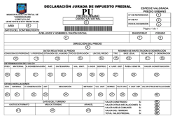
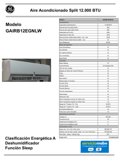
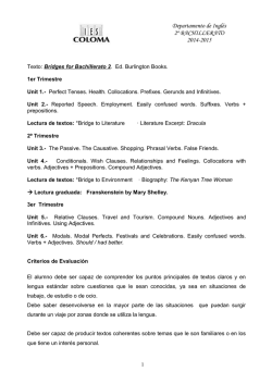
Unit Coolers
KRS
KRS-W
INSTALLATION INSTRUCTIONS
INSTRUCCIONES TÉCNICAS
DE INSTALACIÓN
Original notice
Instrucciones de uso
N° IN0019600
07.2011_es
1.
TECHNICAL DATA - CARACTERÍSTICAS TÉCNICAS
Direct expansion - Expansión directa
Capacity - Potencia (2)
Q0m - HR = 85 %
Air flow - Caudal de aire
DT1 = 10K - tA1 = 8°C
DT1 = 12K - tA1 = 12°C
inlet - entrada
outlet - salida
Glycol water - Agua glicolada (1)
Capacity - Potencia (2)
DT1 = 10K - tA1 = 12°C
Air flow - Caudal de aire
inlet - entrada
Connections - Conexiones
outlet - salida
Connections - Conexiones
Acoustic - Acústica
Lp (3)
Lw(A)
Circuit volume - Volumen circuitos
Fan - Ventilador
230V/1/50Hz
diffuser - difusor / cassette
Net weight - Poids net
diffuser - difusor
Dimensions - (H x L x P)
Dimensiones - (H x L x P)
cassette
diffuser - difusor
Dimensions - Dimensiones
package - embalaje
cassette
kW
kW
m3/h
Ø OD
Ø OD
m3/h
Ø OD
Ø OD
dB(A)
dB(A)
dm3
W max
A max
kg
mm
mm
mm
mm
(1) With glycol water (ethylene glycol 30%) = 0/+4°C.
(2) The evaporation temperature must not be less than -3°C.
(3) Average sound pressure level in dB(A) calculated at 2 meters distance,
in a hemisphere, in a free field on a horizontal reflective plane given as indicative value.
2.
1,6
320
26
40
KRS 1
V2
2,4
3,2
530
3/8"
1/2"
KRS-W 1
2,3
610
1/2”
1/2"
KRS 1 / KRS-W 1
38
52
2
100
0,45
3 / 25
67 x 670 x 670
300 x 632 x 632
150 x 750 x 750
350 x 790 x 790
V3
3,3
4,3
850
V1
3,3
4,3
700
2,8
880
3,3
710
49
63
25
39
KRS 2
V2
4,9
6,4
1200
3/8"
1/2"
KRS-W 2
4,5
1280
3/4"
3/4”
KRS 2 / KRS-W 2
37
51
4
170
0,74
6 / 40
85 x 965 x 965
333 x 879 x 879
200 x 1000 x 1000
400 x 1050 x 1050
V3
6,6
8,7
1880
5,2
1820
47
61
(1) Régimen agua glicolada (etileno glicol 30%) = 0/+4 °C.
(2) La temperatura de evaporación no debe ser inferior a los -3 °C.
(3) Presión sonora en dB(A) calculada a 2 m, superficie de medición hemisférica, en
campo libre sobre plano reflector, indicado con carácter informativo.
DIMENSIONAL DATA - DIMENSIONES
KRS (W) 1
KRS (W) 2
KRS / KRS-W
V1
1,5
2,1
300
2
KRS (W) 1
KRS (W) 2
48 25 34 30
30
30
44
38
21,5
33 31
77
30 149,5
57
29
3.
INSTALLATION - INSTALACIÓN
CAUTION
Remove the fan lock before installation.
Install a safety switch to turn off current to the
appliance in an easily accessible position near
the unit or units. Make sure the unit is earthed.
Do not install in explosive, corrosive or damp
environments, outdoors or in very dusty rooms.
The space above the suspended ceiling must be
dry and adequately protected against moisture
and the ingress of humidity.
If the installation is fitted with an external air
intake damper, make sure the coil tubes are not
damaged by temperatures below freezing point.
During installation, for safety reasons, observe
the following precautions:
• Always use work gloves.
• The unit must always be handled by two
people.
• Fan-coil units should only be carried at suitable
points.
When carrying fan-coil units, gloves should be
worn for safety reasons.
• Lifting tackle and gear must have sufficient
capacity.
• Defective lifting gear and tackle must not be
used.
• Ropes, belts and similar lifting tackle must
not be knotted or come into contact with sharp
edges.
• Fork-lift trucks, elevating-platform trucks and
cranes must have sufficient capacity.
• Loads must not be lifted over persons.
Furthermore, the following is recommended:
Do not remove the safety labels inside the
appliance.
If you cannot read the labels, ask for replacements.
ATENCIÓN
Antes de proceder a la instalación, extraer la
pieza que bloquea la hélice.
Instalar cerca del o de los aparatos y en una
posición de fácil acceso un interruptor de
seguridad para cortar la corriente de la máquina.
Comprobar que se ha efectuado la puesta a
tierra.
No instalar el aparato en una atmósfera explosiva
o corrosiva, en lugares húmedos, en el exterior o
en estancias con mucho polvo.
El espacio encima del techo técnico debe estar
seco y adecuadamente protegido contra la
humedad.
En caso de instalación con una compuerta de
toma de aire exterior, vigilar el hielo en invierno,
que puede provocar la rotura de los tubos de la
batería.
Durante la instalación, por motivos de seguridad,
es necesario respetar las siguientes normas:
• Utilizar siempre guantes de trabajo.
• La manutención de la máquina siempre debe ir
a cargo de dos personas.
• Manipular los ventiloconvectores colocándolos
únicamente en los lugares apropiados.
• Los polipastos y el equipo de elevación deben
tener un alcance suficiente.
• No utilizar polipastos ni equipos de elevación
en mal estado.
• No se deben atar cuerdas, correas ni otras
herramientas para la elevación, tampoco deben
pasar por bordes cortantes.
• Las carretillas elevadoras, los montacargas y
las grúas deben tener un alcance suficiente.
• No se deben colgar las cargas encima de las
personas.
También se recomienda:
No quitar las etiquetas de seguridad del interior
del aparato.
Si no se pueden leer las etiquetas, pedir otros
ejemplares.
3
KRS / KRS-W
WARNING
Electric shock hazard can cause injury or death.
Before attempting to perform any service or maintenance on
the unit, turn OFF the electrical power, and check that the fan
has stopped.
AVISO
Riesgo de electrocución que puede provocar heridas o la
muerte. Antes de proceder a una intervención en la unidad
para mantenimiento o limpieza, es obligatorio cortar la corriente
eléctrica y comprobar que el ventilador ha dejado de girar.
FILTER CLEANING
Check the air filter and make sure it is not
blocked with dustor dirt.
LIMPIEZA DEL FILTRO
Inspeccionar el filtro de aire para comprobar
que no está obstruido por suciedad o polvo.
If the filter is dirty, wash it in a bowl with
neutral soap and water, drying it in the shade
before inserting it in the unit.
Si el filtro está sucio, limpiarlo en un recipiente
con agua y jabón neutro, secarlo a la sombra
antes de volverlo a colocar en la unidad.
A. INSTALLATION TO THE CEILING
A. INSTALACIÓN EN EL TECHO
The unit should be positioned centrally within the room, ensure that
the unit is on level. The unit must be installed in a position where
there is sufficient strength in the structure to support the weight of
the unit. When positioning the appliance, make sure the air intakes
are free from obstructions.
La unidad debe situarse en el centro del local, comprobando que
esté a nivel. La unidad se fijará en una estructura con suficiente
resistencia para aguantar el peso de la unidad. Instalar el aparato
en una posición que no impida la aspiración del aire.
La altura del falso techo debe ser de como mínimo (fig. 1):
- KRS (W) 1 = 310 mm (mín.)
- KRS (W) 2 = 345 mm (mín.)
The false ceiling must have at least a height of (fig. 1):
- KRS (W) 1 = 310 mm (min.)
- KRS (W) 2 = 345 mm (min.)
Comprobar que hay suficiente espacio libre alrededor de la unidad
para efectuar su mantenimiento (fig. 2).
En caso de falso techo modular, comprobar que hay suficiente
espacio para colocar los paneles de falso techo.
Ensure there is sufficient space around the unit to service it. Where
there is a false ceiling ensure that there is enough space to provide
access (fig. 2).
Where there is a false panelled ceiling, ensure that there is sufficient
space adjacent to remove the panels.
Cut the false ceiling to:
KRS (W) 1 - mínimo: 590 x 590 mm - máximo: 630 x 630 mm.
KRS (W) 2 - mínimo: 840 x 840 mm - máximo: 900 x 900 mm.
Cut the false ceiling to:
KRS (W) 1 - minimun : 590 x 590 mm - maximum : 630 x 630 mm.
KRS (W) 2 - minimun : 840 x 840 mm - maximum : 900 x 900 mm.
Cassette fixing:
El cassette está fijado en el techo estructural mediante barras
roscadas, no incluidas.
Cassette fixing:
The fan-coil unit is fixed to the structural ceiling by means of
threaded rods to be provided by others.
Procedure:
• Marcar las posiciones de los agujeros en el techo estructural en
los dos lados opuestos a la abertura practicada en el techo técnico.
A continuación, realizar los agujeros en las barras roscadas (las
dimensiones están indicadas en los esquemas del lado) (fig. 3).
Procedure:
• The hole positions in the structural ceiling must first be marked by
reference to the two opposite sides of the cutout in the suspended
ceiling and the holes for the threaded rods must then be drilled (fig. 3).
NOTE: Antes de marcar los puntos de fijación en el techo,
comprobar la orientación correcta de la unidad, teniendo en cuenta
la posición de la conexión en la caja eléctrica del refrigerante.
Una vez fijada la unidad, es difícil modificar su posición.
NOTE: Before marking the fixing points to the ceiling, ensure that
the unit is positioned in the correct orientation taking into account
of where the electrical cabinet and refrigerant connections are
required. When the unit is fixed it is not easy to change position.
• Fijar las barras roscadas en el techo. La longitud de las barras
depende del espacio entre el techo técnico y el techo estructural.
• The threaded rods must then be fixed in the ceiling. The length
of the rods depends on the clearance between the suspended
ceiling and the structural ceiling.
• Inclinar el cassette, empujarlo a través de la abertura, con la caja
de bornes hacia arriba, situarlo en posición horizontal encima de la
obertura (fig. 5).
• The fan-coil unit is then tilted and pushed through the cutout with
the terminal box on top and then placed level over the cutout (fig. 5).
• Los ganchos en los estribos permiten instalar provisionalmente
el aparato.
• The hooks on the brackets allow a quick temporary installation.
Following positioning, the brackets must be attached to the
appliance walls by means of tapping screws.
• A continuación fijar el aparato a las barras roscadas (fig. 6).
Es obligatorio que el aparato esté en posición completamente
horizontal.
• The appliance must then be fixed to the threaded rods (fig. 6).
It is essential for the appliance to be exactly level. The unit can be
installed using any other method considered appropriate by the
installer, providing it is in accordance with current legislation.
KRS / KRS-W
El instalador podrá instalar el aparato con cualquier medio que
considere apropiado, siempre que respete las normas vigentes.
4
1
3
364
Min.
657
KRS (W) 1 = 310 mm
KRS (W) 2 = 345 mm
748
2
00*
5
Min.
748
5
Min.
00 *
* Always keep free
* Este espacio siempre deberá quedar
29
5
6
18
0
25
270
4
B. DRAIN CONNECTION
B. CONEXIÓN DEL DRENAJE
• To ensure that there is condensate flow, the drain tube must be
installed with a fall of 2% withour obstructions, or without rising
sections.
• Para asegurar la evacuación de los condensados, se colocará
el tubo de drenaje con una pendiente del 2% sin obstáculos ni
subidas.
• To avoid any unpleasant odours from the drainage system a trap
must be fitted with a trap depth of no less than 50mm.
• Para evitar que el sistema de drenaje desprenda malos olores, se
instalará un sifón con una profundidad de como mínimo 50 mm.
• On completion the drain line must be insulated.
• Tras la instalación, se aislará el conducto de drenaje.
• The condensation discharge hose, located near the water
connections, features:
- length = 470 mm
- connection external diameter = 14 mm
• El tubo de purga de condensación, que sale cerca de las
conexiones hidráulicas, posee las siguientes características:
- Longitud = 470 mm
- Diámetro exterior de la conexión = 14 mm
• The maximum discharge head of the pump is 650 mm from the
bottom edge of the appliance.
• La altura de descarga máxima de la bomba es de 650 mm a
partir del borde inferior del aparato.
5
KRS / KRS-W
C. EXPANSION VALVE MOUNTING
C. MONTAJE DE LA VÁLVULA DE EXPANSIÓN
Expansion valve must be fitted as near as possible to the inlet of
the unit.
It must be insulated to avoid condensation and water dripping.
Insulation thickness should be at least equal to the outside
insulation of the casing.
La válvula de expansión se montará lo más cerca posible del orificio
de entrada de la unidad.
Es imperativo aislarla para evitar la condensación y la formación
de gotas de agua.
El grosor del aislamiento debe ser como mínimo igual al del
aislamiento externo de la caja.
D. ELECTRICAL CONNECTION
D. CONEXIÓN ELÉCTRICA
WARNING
Electric shock hazard can cause injury or death.
Before attempting to perform any service or maintenance on
the unit, turn OFF the electrical power, and check that the fan
has stopped.
AVISO
Riesgo de electrocución que puede provocar heridas o la
muerte. Antes de proceder a una intervención en la unidad
para mantenimiento o limpieza, es obligatorio cortar la corriente
eléctrica y comprobar que el ventilador ha dejado de girar.
• Perform electrical connections in accordance with laws and
regulations in force in the country concerned.
• Efectuar las conexiones eléctricas según la legislación y las
normas nacionales vigentes.
• The wiring diagrams do not address protective grounding or
other electrical protection which will be required under local rules,
regulations, codes and standards or by the local electricity supplier.
• Los esquemas eléctricos no tienen en cuenta la puesta a tierra
u otros tipos de protección eléctrica previstos por las normas,
reglas, legislación y estándares locales o del proveedor de energía
eléctrica.
• Before installing the fan coil, make sure the rated voltage of the
power supply is 230V - 50 Hz.
• Antes de instalar el cassette, comprobar que la tensión de
alimentación nominal es de 230V – 50Hz.
• The power supply is always connected to terminals L, N on the
board.
• La alimentación eléctrica siempre está conectada a los bornes L,
N de la tarjeta.
• Maximum power consumption for 230 VAC mains power operation
is : KRS (W) 1 : 0.45A - KRS (W) 2 : 0.74A
• La potencia máxima absorbida para el funcionamiento con la
tensión de 230 V c.a es: KRS (W) 1: 0.45A - KRS (W) 2: 0,74A
If using the Cassette fan coils with electronic controllers,
the voltage values at the autotransformer terminals
must be kept in consideration (transformer return voltages).
These values may reach 500 Vac.
En caso de asociar el cassette con reguladores
electrónicos, es obligatorio tener en cuenta los valores
de la tensión en los bornes del autotransformador (tensión
transformada). Estos valores pueden alcanzar los 500 Vac.
• Upstream of the unit, fi t an omnipolar switch with minimum
contact distance of 3 mm.
• Aguas arriba de la unidad, prever un interruptor unipolar con una
distancia mínima de los contactos de 3 mm.
• The unit must always be earthed.
• Siempre se debe realizar la puesta a tierra de la unidad.
• Always disconnect the electrical power supply before opening
the unit.
• Desconectar siempre la máquina antes de acceder a la misma.
• The minimum cross section of the electric wires is 0.75 mm2.
• La sección mínima de los conductores es de 0,75 mm2
Ø21.5
PG 13.5
KRS / KRS-W
PG 13.5
6
STANDARD ELECTRICAL CONNECTION
CONEXIÓN ELÉCTRICA ESTÁNDAR
T1
M9
B1
LEGEND:
--------- Heatcraft wiring
- - - - External connection responsability of the installer
C1
M
ECTUEE PAR
6 5 4 3 2 1 MML
1
PONSABILITY OF
M
Fan motor
Sec1 Electronic board
T1Autotransformer
C1Capacitor
B1 Condensate level sensor
M9 Water pump motor
S1 Alarm condensate contact
NC Usually closed
C Common
NO Usually open
M5
DES CONDENSATS
SEC1
1 2 3
CONDENSACION
S1
M7 M6
4 5 6 7
M2
M1
8 9 10 L
N
BU
BK
BN
RD
J4
BK
OG
RD
WH
WH
BU
BN
BK
BK
BN
OG
WH
BK
BN
BU
J5
J3
J1
NSATS
OG
NSTALLATEUR
O DEL
V2
V3
J2
V1
M4
BK BN BU OG RD WH V3 V1
V2
CONDENSACION
M3
N
N
L
CC
M9
B1
TACT
Speed :
V1 Low speed
V2 Medium speed
V3 High speed
PE
M
C1
L
M
L1
T1
L2
LEYENDA:
--------- Cableado Heatcraft
- - - - Conexión exterior efectuada por el instalador.
109 V 134V
M
L6
L5
L4
RD
R
L3
1
208V 187V 165 V
HINWEISE
RKINGEN
J1
J5
J3
M5
SEC1
1 2 3
S1
M7 M6
4 5 6 7
M2
M1
8 9 10 L
N
BK
OG
RD
WH
WH
BU
BN
J4
V2
V3
J2
V1
M4
V3 V1
V2
M3
KRS (W) 2
N
N
L
DAD MINIMA
SPEED
IDAD MEDIA
NC
C
NO
DAD MAXIMA
High level
Condensate
Alarm
SPDT relay
Contact
L
N
230V/50Hz
CC
M
Sec1 T1 C1 B1 M9 S1 NC C
NO Motoventilador
Caja de bornes cassette
Autotransformador
Condensador
Sonda nivel de los condensados
Motor de bomba de agua
Relé seguridad alto nivel de los condensados
Normalmente cerrado
Común
Normalmente abierto
BK BN BU OG RD WH Negro
Marrón
Azul
Naranja
Rojo
Blanco
Velocidades:
V1 Velocidad mín.
V2 Velocidad media
V3 Velocidad máx.
V3
V2
V1
NEGRO
MARRON
AZUL
NARANJA
ROJO
BLANCO
BK
BN
BU
BN
OG
WH
OLORES
BK
BK
OG
0 230 V
DERING
SS
N
230V/50Hz
BU
NDENSATSTAND
L
High level
Condensate
Alarm
SPDT relay
Contact
BN
NC
C
NO
RM
WARZ
UN
U
NGE
V3
V2
V1
KRS (W) 1
Black
Brown
Blue
Orange
Red
White
PE
ELECTRICAL CONNECTION : OTHER SPEEDS - CONEXIÓN ELÉCTRICA: OTRAS VELOCIDADES
Speed - Velocidades
Connections - Conectores
Voltage - Tensión
Direct expansion - Expansión directa
DT1 = 10K - tA1 = 8°C
Capacity - Potencia
DT1 = 12K - tA1 = 12°C
Air flow - Caudal de aire
Glycol water - Agua glicolada
Capacity - Potencia
DT1 = 10K - tA1 = 12°C
Air flow - Caudal de aire
Rotation - Rotación
Acoustic
Acústica
Lp (2)
Lw(A)
n°
V
V1
6
92
5
120
4
132
kW
kW
m3/h
1,5
2,1
300
2,0
2,6
409
KRS 1
2,1
2,4
2,8
3,2
453
530
2,7
3,5
620
3,3
4,3
850
kW
m3/h
1,6
320
1,9
430
KRS-W 1
2,1
2,3
500
610
2,5
710
r.p.m.
dB(A)
dB(A)
400
26
40
540
33
47
KRS 1 / KRS-W 1
600
700
820
35
38
42
49
52
56
7
V2
3
150
2
170
V3
1
230
V1
L1
109
L2
134
V2
L3
165
L4
187
L5
208
V3
L6
230
3,3
4,3
700
4,0
5,2
900
KRS 2
4,9
5,5
6,4
7,2
1200 1400
6,1
8,1
1680
6,6
8,7
1880
2,8
880
3,3
710
3,9
970
KRS-W 2
4,5
4,8
1280 1500
5,1
1675
5,2
1820
1120
49
63
280
25
39
360
31
45
KRS 2 / KRS-W 2
470
560
670
37
41
44
51
55
58
750
47
61
KRS / KRS-W
E. DIFFUSER INSTALLATION
7
4.
E. INSTALACIÓN DEL DIFUSOR
8
9
CLEANING, MAINTENANCE AND SPARE PARTS - LIMPIEZA, MANTENIMIENTO Y PIEZAS DE RECAMBIO
Maintenance of the unit must be carried out by
trained maintenance personnel only.
Fan-coil units must be disconnected from
mains power and secured against unintentional
re-connection before any maintenance work.
All work must be in accordance with all applicable
safety and health rules and regulations.
Sólo el personal encargado del mantenimiento y con
formación específica puede intervenir en los aparatos.
Antes de realizar cualquier intervención,
desconectar el cassette y comprobar que no
puede volver a conectarse involuntariamente.
Todas las actuaciones se efectuarán según las normas
y reglas vigentes en materia de seguridad y salud.
FAN: No maintenance required.
VENTILADOR: No requiere ningún tipo de
mantenimiento.
COIL: No ordinary maintenance required.
FILTER: The filter pad may be cleaned or replaced.
For cleaning, a vacuum-cleaner operating at medium
or low suction should be used.
If the filter is dirty, wash it in a bowl with neutral soap
and water, drying it in the shade before inserting it
in the unit.
When it can no longer be cleaned, replace.
For replacement, the fasteners of the intake grille
must be opened and the grille must be removed.
Finally, the intake grille must again be locked in place.
SPARE PARTS:
To order spare parts, always give the model of
appliance and a description of the component.
IMPORTANT!
BEFORE CARRYING OUT CLEANING OR
MAINTENANCE, MAKE SURE THE POWER TO THE
UNIT IS TURNED OFF.
IMPORTANT!
ALWAYS REPLACE THE FILTER AFTER CLEANING.
HEATCRAFT se réserve le droit d'apporter toute modification sans préavis.
HEATCRAFT reserves itself the right to make changes at any time without preliminary notice.
HEATCRAFT Angaben und Abbildungen unverbindlich. Änderungen vorbehalten.
HEATCRAFT se reserva el derecho de aportar modificaciones sin previo aviso.
BATERÍA: No requiere ningún tipo de mantenimiento
ordinario.
FILTRO: El filtro se puede limpiar o sustituir.
Para la limpieza, utilizar un aspirador con aspiración
baja o media.
Si el filtro está sucio, limpiarlo en un recipiente con
agua y jabón neutro, secarlo a la sombra antes de
volverlo a colocar en la unidad.
Sustituirlo cuando ya no se pueda limpiar.
Para sustituir el filtro, abrir las fijaciones, retirar la
rejilla de la toma de aire y sustituir el filtro.
Finalmente, colocar de nuevo la rejilla de la toma
de aire.
PIEZAS DE RECAMBIO:
Para pedir piezas de recambio, se debe indicar el
modelo del aparato y la descripción del componente.
¡ATENCIÓN!
ANTES DE REALIZAR CUALQUIER OPERACIÓN
DE LIMPIEZA Y MANTENIMIENTO, CORTAR LA
ALIMENTACIÓN DEL APARATO.
¡ATENCIÓN!
TRAS REALIZAR LA LIMPIEZA, RECORDAR
VOLVER A MONTAR EL FILTRO.
42 rue Roger Salengro - BP 205
69741 GENAS CEDEX - FRANCE
Tél. : + 33 4 72 47 13 00 - Fax : + 33 4 72 47 13 96
Internet : www.heatcrafteurope.com

© Copyright 2026